

Briggs & Stratton 130G00, 131G00, 13R200, 13U100, 13U200 Repair Manual

Not for
Reproduction

Not for
Reproduction

Not for
Reproduction
Foreword
This manual was written to assist engine technicians and service personnel with the maintenance and repair
procedures for Briggs & Stratton® engines. It assumes that persons using this manual have been properly
trained and are familiar with the service procedures for these products, including the proper use of required
tools and the application of appropriate safety practices. Persons untrained or unfamiliar with these procedures
or products should not attempt to perform such work.
Proper maintenance and repair is important to safe, reliable operation of all engines and engine-driven
systems. The maintenance, troubleshooting, and repair procedures described in this manual are appropriate
for the Briggs & Stratton engines described herein. Alternative methods or procedures may pose risks to
both personal safety and engine reliability and are not endorsed or recommended by Briggs & Stratton.
All information, illustrations, and specifications contained in this manual were based on the data available
at the time of publication. Briggs & Stratton Corporation reserves the right to change, alter, or otherwise
improve the product or the product manuals at any time without prior notice.
Briggs & Stratton offers two complementary publications to enhance understanding of engine technology,
maintenance, and repair. However, neither publication is a substitute for a recognized training program for
engine technicians.
• For consumers,
comprehensive overview of how small air-cooled engines work, basic troubleshooting, and step-by-step
maintenance procedures.
• For engine technicians and consumers alike, an in-depth study of engine theory and operation can be
found in the textbook
Both publications can be purchased at BRIGGSandSTRATTON.COM or through a local Briggs & Stratton
Authorized Service Dealer.
Copyright © 2017 Briggs & Stratton Corporation.
All rights reserved.
No part of this manual may be reproduced or transmitted in any form or by any means, electronic or
mechanical, including photocopying or recording by any information storage and retrieval system, without
prior written permission from Briggs & Stratton Corporation.
Small Engine and Equipment Maintenance Guide
Small Engines
(Part No. CE8020).
(Part No. CE8155) provides a

Not for
Reproduction
This engine repair manual includes the following engine models:
• MODEL 130G00
• MODEL 131G00
• MODEL 13R200
• MODEL 13U100
• MODEL 13U200
NOTE: Some models have limited service parts. Review the
before conducting any service work.
NOTE: The images in this document are representative and may differ according to model.
Illustrated Parts List
for part availability

Not for
Reproduction
HOW TO USE THIS MANUAL
Besides describing the service maintenance tasks and the intervals at which they are to be performed, two
basic levels of service are presented in this manual: engine top end service and engine bottom end service.
The manner in which these instructions are used depends upon the tasks to be performed and the level of
disassembly required.
Remove External Assemblies
To prepare the engine for service, whether top or bottom end, first see
ASSEMBLIES
presented is the order in which the assemblies are most easily removed from the engine.
NOTE: A few exceptions to this rule do exist, such as the muffler and rewind starter, which may be serviced
without having to remove other external assemblies.
Top End Service
If servicing only cylinder head components, see
DISASSEMBLY,
HEAD.
ASSEMBLY.
Bottom End Service
If servicing bottom end components, such as the piston, connecting rod, crankshaft, etc., first see
5 - DISASSEMBLE ENGINE, TOP END DISASSEMBLY,
DISASSEMBLY
SUBASSEMBLIES,
CAMSHAFT;
end service is complete, see
proceed to
Install External Assemblies
When cylinder head service is complete, see
to remove the air cleaner, fuel tank, carburetor, etc. The order in which the topics are
SECTION 5 - DISASSEMBLE ENGINE, TOP END
and then proceed to
in the same section. When finished, move to
and see
and
CRANKCASE AND CRANKCASE COVER,
TOP END ASSEMBLY
PISTON AND CONNECTING ROD; FLYWHEEL, CRANKSHAFT AND
SECTION 7 - ASSEMBLE ENGINE, BOTTOM END ASSEMBLY,
SECTION 6 - SERVICE ENGINE SUBASSEMBLIES, CYLINDER
SECTION 7 - ASSEMBLE ENGINE, TOP END
and then proceed to
SECTION 6 - SERVICE ENGINE
in the same section.
SECTION 4 - REMOVE EXTERNAL
SECTION
BOTTOM END
for all service instructions. When bottom
and then
When the top and bottom ends of the engine are assembled, see
ASSEMBLIES
the assemblies are most easily installed on the engine. These instructions also include any cleaning,
inspection, or adjustments that may be recommended.
to complete the project. The order in which the topics are presented is the order in which
SECTION 8 - INSTALL EXTERNAL

Not for
Reproduction

Not for
Reproduction
SECTION 1 – SAFETY AND GENERAL INFORMATION
SECTION 2 – MAINTENANCE
SECTION 3 – TROUBLESHOOTING/SPECIAL TOOLS
SECTION 4 – REMOVE EXTERNAL ASSEMBLIES
SECTION 5 – DISASSEMBLE ENGINE
SECTION 6 – SERVICE ENGINE SUBASSEMBLIES
SECTION 7 – ASSEMBLE ENGINE
1
2
3
4
5
6
7
SECTION 8 – INSTALL EXTERNAL ASSEMBLIES
SECTION 9 – SPECIFICATIONS
8
9

Not for
Reproduction

Not for
Reproduction
SECTION 1 – SAFETY AND GENERAL INFORMATION
SAFETY - - - - - - - - - - - - - - - - - - - - - - - - - - - - - - - - - - - - - - - - - - - - - - - - - - - - - - - - - - - - - - - - - - - - - - - - - - - - - - - 4
Safety Alert Symbol and Signal Words - - - - - - - - - - - - - - - - - - - - - - - - - - - - - - - - - - - - - - - - - - - - - - - - - - - - - - 4
Hazard Symbols and Meanings - - - - - - - - - - - - - - - - - - - - - - - - - - - - - - - - - - - - - - - - - - - - - - - - - - - - - - - - - - - 4
General Safety Messages - - - - - - - - - - - - - - - - - - - - - - - - - - - - - - - - - - - - - - - - - - - - - - - - - - - - - - - - - - - - - - - 4
GENERAL INFORMATION - - - - - - - - - - - - - - - - - - - - - - - - - - - - - - - - - - - - - - - - - - - - - - - - - - - - - - - - - - - - - - - - - 7
Engine Identification - - - - - - - - - - - - - - - - - - - - - - - - - - - - - - - - - - - - - - - - - - - - - - - - - - - - - - - - - - - - - - - - - - - 7
Fuel Recommendations - - - - - - - - - - - - - - - - - - - - - - - - - - - - - - - - - - - - - - - - - - - - - - - - - - - - - - - - - - - - - - - - - 7
High Altitude - - - - - - - - - - - - - - - - - - - - - - - - - - - - - - - - - - - - - - - - - - - - - - - - - - - - - - - - - - - - - - - - - - - - - - - - - 7
Oil Recommendations - - - - - - - - - - - - - - - - - - - - - - - - - - - - - - - - - - - - - - - - - - - - - - - - - - - - - - - - - - - - - - - - - - 7
Storage - - - - - - - - - - - - - - - - - - - - - - - - - - - - - - - - - - - - - - - - - - - - - - - - - - - - - - - - - - - - - - - - - - - - - - - - - - - - 8
1
3
Not for
Reproduction
This manual contains safety information that will:
• Make you aware of hazards associated with engines.
1
• Inform you of the risk of injury associated with those
hazards.
• Instruct you how to avoid or reduce the risk of injury.
Safety Alert Symbol and Signal Words
The safety alert symbol is used to identify safety
information about hazards that can result in personal injury.
A signal word (DANGER, WARNING, or CAUTION) is used
with the alert symbol to indicate the likelihood and the
potential severity of injury. In addition, a hazard symbol may
be used to represent the type of hazard.
DANGER indicates a hazard which, if not avoided, will
result in death or serious injury.
WARNING indicates a hazard which, if not avoided,
could result in death or serious injury.
SAFETY
General Safety Messages
Prior to work, read and understand the section(s) of this
manual that pertain to the job. Follow all safety warnings.
• Always use fresh gasoline. Stale fuel can cause gum
deposits in the carburetor and cause leakage, flow
restrictions, or other problems.
• Check fuel lines and fittings frequently for cracks or
leaks and replace if necessary.
WARNING
Before attempting to service this equipment, read and
understand this manual and the operating instructions of
the engine and the equipment.
WARNING
Failure to follow instructions could result in serious injury
(including paralysis) and even death.
CAUTION indicates a hazard which, if not avoided,
could result in minor or moderate injury.
NOTICE
to the product.
indicates an situation that could result in damage
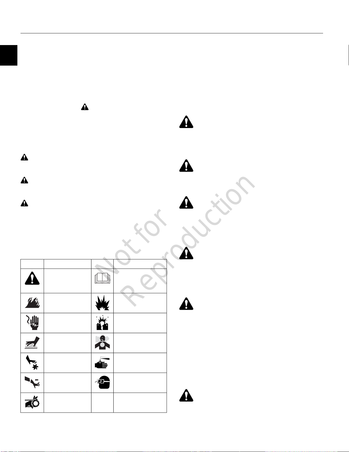
Hazard Symbols and Meanings
MeaningSymbolMeaningSymbol
Safety information
about hazards that can
result in personal
injury.
moving parts
Kickback hazard
Read and understand the
Operator's Manual before
operating or servicing the
unit.
Explosion hazardFire hazard
Explosion hazardShock hazard
Toxic fume hazardHot surface hazard
Chemical hazardAmputation hazard -
Thrown object hazard wear eye protection
WARNING
Battery post, terminals, and related accessories contain
lead and lead compounds - chemicals known to the State
of California to cause cancer and reproductive harm. Wash
hands after handling.
WARNING
Certain components in this product and its related
accessories contain chemicals known to the State of
California to cause cancer, birth defects, or other
reproductive harm. Wash hands after handling.
WARNING
Briggs & Stratton Engines are not designed for and are
not to be used to power: fun-karts; go-karts; children's,
recreational, or sport all-terrain vehicles (ATVs);
motorbikes; hovercraft; aircraft products; or vehicles used
in competitive events not sanctioned by Briggs & Stratton.
For information about competitive racing products, see
www.briggsracing.com. For use with utility and
side-by-side ATVs, please contact Briggs & Stratton Power
Application Center, 1-866-927-3349. Improper engine
application may result in serious injury or death.
Amputation hazard entanglement
4
WARNING
The engine exhaust from this product contains chemicals
known to the State of California to cause cancer, birth
defects, or other reproductive harm.
Not for
Reproduction
WARNING
Fuel and its vapors are extremely flammable and explosive
which could cause burns, fire or explosion resulting in
death or serious injury.
When Adding Fuel
• Turn engine OFF and let engine cool at least 2 minutes
before removing the fuel cap. Loosen cap slowly to
relieve pressure in tank.
• Fill fuel tank outdoors or in well-ventilated area.
• Do not overfill fuel tank. To allow for expansion of the
fuel, do not fill above the bottom of the fuel tank neck.
• Keep fuel away from sparks, open flames, pilot lights,
heat, and other ignition sources.
• Check fuel lines, tank, cap, and fittings frequently for
cracks or leaks. Replace if necessary.
• If fuel spills, wait until it evaporates before starting
engine.
• Do not light a cigarette or smoke.
When Starting Engine
• Ensure that spark plug, muffler, fuel cap and air cleaner
(if equipped) are in place and secured.
• Do not crank engine with spark plug removed.
• If engine floods, set choke (if equipped) to OPEN / RUN
position, move throttle (if equipped) to FAST position
and crank until engine starts.
When Operating Equipment
• Do not tip engine or equipment at angle which causes
fuel to spill.
• Disconnect spark plug wire.
When Storing Fuel or Equipment with Fuel In Tank
• Store away from furnaces, stoves, water heaters,
clothes dryers, or other appliances that have pilot lights
or other ignition source because they could ignite fuel
vapors.
WARNING
Starting engine creates sparking which could ignite nearby
flammable gases causing explosion or fire resulting in
death or serious injury.
• If there is natural or LP gas leakage in the area, do not
start engine.
• Do not use pressurized starting fluids because vapors
are flammable.
WARNING
POISONOUS GAS HAZARD. Engine exhaust contains
carbon monoxide, a poisonous gas that could kill you in
minutes. You CANNOT see it, smell it, or taste it. Even if
you do not smell exhaust fumes, you could still be exposed
to carbon monoxide gas. If you start to feel sick, dizzy, or
weak while using this product, get to fresh air RIGHT
AWAY. See a doctor. You may have carbon monoxide
poisoning.
1
• Do not operate this product inside any building, carport,
porch, mobile equipment, marine applications, or
enclosure.
• Do not tip engine or equipment at angle which causes
fuel to spill.
• Do not choke the carburetor to stop engine.
• Never start or run the engine with the air cleaner
assembly (if equipped) or the air filter (if equipped)
removed.
When Changing Oil
• If you drain the oil from the oil fill hole (not
recommended), the fuel tank must be empty or fuel can
leak out and result in a fire or explosion.
When Tipping Unit for Maintenance
• When performing maintenance that requires the unit to
be tipped, the fuel tank, if mounted on the engine, must
be empty or fuel can leak out and result in a fire or
explosion.
When Transporting Equipment
• Transport/move/repair with fuel tank EMPTY or with
fuel shutoff valve OFF.
• Operate this product ONLY outside far away from
windows, doors and vents to reduce the risk of carbon
monoxide gas from accumulating and potentially being
drawn towards occupied spaces.
• Install battery-operated carbon monoxide alarms or
plug-in carbon monoxide alarms with battery back-up
according to the manufacturer's instructions. Smoke
alarms cannot detect carbon monoxide gas.
• DO NOT run this product inside homes, garages,
basements, crawlspaces, sheds, or other
partially-enclosed spaces even if using fans or opening
doors and windows for ventilation. Carbon monoxide
can quickly build up in these spaces and can linger for
hours, even after this product has shut off.
• ALWAYS place this product downwind and point the
engine exhaust away from occupied spaces.
WARNING
Starter cord kickback (rapid retraction) will pull hand and
arm toward engine faster than you can let go which could
cause broken bones, fractures, bruises, or sprains
resulting in serious injury.
5
Not for
Reproduction
• When starting engine, pull the starter cord slowly until
resistance is felt and then pull rapidly to avoid kickback.
• Remove all external equipment / engine loads before
starting engine.
1
• Direct-coupled equipment components such as, but not
limited to, blades, impellers, pulleys, sprockets, etc.,
must be securely attached.
WARNING
Rotating parts could entangle hands, feet, hair, clothing,
or accessories resulting in serious injury.
• Disconnect the spark plug wire and keep it away from
the spark plug.
• Disconnect battery at negative terminal (only engines
with electric start.)
• Use only correct tools.
• Do not tamper with governor spring, links or other parts
to increase engine speed.
• Replacement parts must be of the same design and
installed in the same position as the original parts. Other
parts may not perform as well, may damage the unit,
and may result in injury.
• Do not strike the flywheel with a hammer or hard object
because the flywheel may later shatter during operation.
• NEVER operate equipment without protective housing
or covers in place.
• DO NOT wear loose clothing, jewelry or anything that
could become entangled in the equipment.
• Tie up long hair and remove jewelry.
• Keep hands and feet away from rotating parts.
WARNING
Running engines produce heat. Engine parts, especially
mufflers, become extremely hot which could cause severe
thermal burns or catching fire to combustible debris, such
as leaves, grass, brush, etc., resulting in serious injury.
• Allow muffler, engine cylinder and fins to cool before
touching.
• Remove accumulated debris from muffler area and
cylinder area.
• It is a violation of California Public Resource Code,
Section 4442, to use or operate the engine on any
forest-covered, brush-covered, or grass-covered land
unless the exhaust system is equipped with a spark
arrester, as defined in Section 4442, maintained in
effective working order. Other states or federal
jurisdictions may have similar laws. Contact the original
equipment manufacturer, retailer, or dealer to obtain a
spark arrester designed for the exhaust system installed
on this engine.
WARNING
Unintentional sparking could cause fire or electric shock
resulting in death or serious injury.
Unintentional start-up could result in entanglement,
traumatic amputation, or laceration.
When testing for spark:
• Use approved spark plug tester.
• Do not check for spark with spark plug removed.
WARNING
Charging batteries produce hydrogen gas which could
cause explosion resulting in death or serious injury.
• Do not store or charge a battery near an open flame or
device that utilizes a pilot light or can create a spark.
WARNING
Damaged, worn, or loose fuel components can leak fuel
which could cause explosion or fire resulting in death or
serious injury.
• All fuel components should be in good condition and
properly maintained.
• Repairs should only be made with factory approved
parts.
• Repair work should be done by a qualified technician.
• Flexible supply lines should be checked regularly to
make sure they are in good condition.
WARNING
Prolonged or repeated contact with used motor oil could
cause injury.
• Used motor oil has been shown to cause skin cancer
in certain laboratory animals.
• Thoroughly wash exposed areas with soap and water.
Before performing adjustments or repairs:
6
NOTICE
Failure to follow instructions could result in property
damage.
Not for
Reproduction
GENERAL INFORMATION
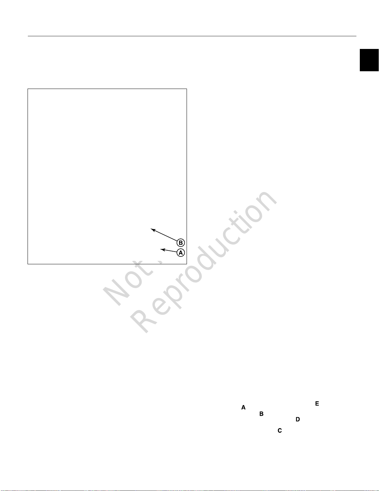
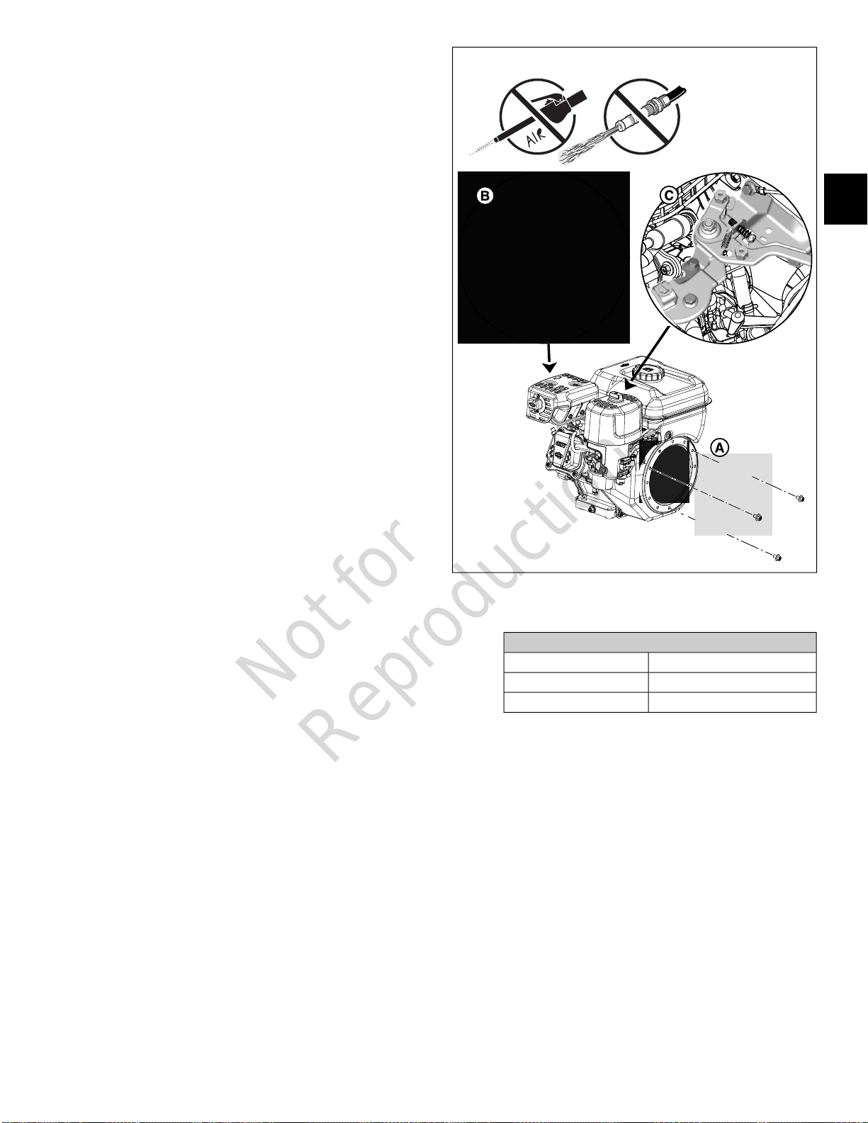
Engine Identification
See (A) or (B) in Figure 1 for location of engine
identification.
1
High Altitude
At altitudes over 5,000 feet (1524 meters), a minimum 85
octane / 85 AKI (89 RON) gasoline is acceptable.
For carbureted engines, high altitude adjustment is required
to remain emissions compliant. Operation without this
adjustment will cause decreased performance, increased
fuel consumption, and increased emissions. Contact a
Briggs & Stratton Authorized Service Dealer for high altitude
adjustment information. Operation of the engine at altitudes
below 2,500 feet (762 meters) with the high altitude
adjustment is not recommended.
For Electronic Fuel Injection (EFI) engines, no high altitude
adjustment is necessary.
Oil Recommendations
Oil Capacity: See the
NOTICE
This engine was shipped from Briggs & Stratton without
oil. Equipment manufacturers or dealers may have added
oil to the engine. Before you start the engine for the first
time, make sure to check the oil level and add oil
according to the instructions in this manual. If you start
the engine without oil, it will be damaged beyond repair
and will not be covered under warranty.
Specifications
section.
1
Fuel Recommendations
Fuel must meet these requirements:
• Clean, fresh, unleaded gasoline.
• A minimum of 87 octane / 87 AKI (91 RON). For high
altitude use, see below.
• Gasoline with up to 10% ethanol (gasohol) is
acceptable.
NOTICE
and E85. Do not mix oil in gasoline or modify the engine
to run on alternate fuels. Use of unapproved fuels will
cause damage to engine components, which will not be
covered under warranty.
To protect the fuel system from gum formation, mix a fuel
stabilizer into the fuel. See Storage. All fuel is not the same.
If starting or performance problems occur, change fuel
providers or change brands. This engine is certified to
operate on gasoline. The emissions control system for this
engine is EM (Engine Modifications).
Do not use unapproved gasolines, such as E15
We recommend the use of Briggs & Stratton Warranty
Certified oils for best performance. Other high-quality
detergent oils are acceptable if classified for service SF,
SG, SH, SJ or higher. Do not use special additives.
Outdoor temperatures determine the proper oil viscosity for
the engine. Use the chart to select the best viscosity for the
outdoor temperature range expected. Engines on most
outdoor power equipment operate well with 5W-30 Synthetic
oil. For equipment operated in hot temperatures,
Vanguard™ 15W-50 Synthetic oil provides the best
protection.
7

Not for
Reproduction
SAE 30 - Below 40 °F (4 °C) the use of SAE 30 will result in hard
A
starting.
10W-30 - Above 80 °F (27 °C) the use of 10W-30 may cause
B
increased oil consumption. Check oil level more frequently.
5W-30C
1
Synthetic 5W-30D
Vanguard™ Synthetic 15W-50E
Storage
Fuel can become stale when stored over 30 days. Stale
fuel causes acid and gum deposits to form in the fuel system
or on essential carburetor parts. To keep fuel fresh, use
Briggs & Stratton® Advanced Formula Fuel Treatment
& Stabilizer, available wherever Briggs & Stratton genuine
service parts are sold.
There is no need to drain gasoline from the engine if a fuel
stabilizer is added according to instructions. Run the engine
for 2 minutes to circulate the stabilizer throughout the fuel
system before storage. If gasoline in the engine has not
been treated with a fuel stabilizer, it must be drained into
an approved container. Run the engine until it stops from
lack of fuel. The use of a fuel stabilizer in the storage
container is recommended to maintain freshness.
8

Not for
Reproduction
SECTION 2 – MAINTENANCE
MAINTENANCE - - - - - - - - - - - - - - - - - - - - - - - - - - - - - - - - - - - - - - - - - - - - - - - - - - - - - - - - - - - - - - - - - - - - - - - - 10
Maintenance Schedule - - - - - - - - - - - - - - - - - - - - - - - - - - - - - - - - - - - - - - - - - - - - - - - - - - - - - - - - - - - - - - - - - 10
Change Engine Oil/Check Engine Oil Level - - - - - - - - - - - - - - - - - - - - - - - - - - - - - - - - - - - - - - - - - - - - - - - - - - 10
Clean Muffler, Rewind Starter Finger Guard, and Controls - - - - - - - - - - - - - - - - - - - - - - - - - - - - - - - - - - - - - - - - 11
Clean/Replace Air Filter and Pre-Cleaner - - - - - - - - - - - - - - - - - - - - - - - - - - - - - - - - - - - - - - - - - - - - - - - - - - - - 11
Dual Element Oval Air Filter - - - - - - - - - - - - - - - - - - - - - - - - - - - - - - - - - - - - - - - - - - - - - - - - - - - - - - - - - - 12
Oil Bath Air Filter - - - - - - - - - - - - - - - - - - - - - - - - - - - - - - - - - - - - - - - - - - - - - - - - - - - - - - - - - - - - - - - - - - 12
Foam Low Mount Air Filter - - - - - - - - - - - - - - - - - - - - - - - - - - - - - - - - - - - - - - - - - - - - - - - - - - - - - - - - - - - 13
Foam Large Panel Air Filter - - - - - - - - - - - - - - - - - - - - - - - - - - - - - - - - - - - - - - - - - - - - - - - - - - - - - - - - - - 13
Paper Air Filter - - - - - - - - - - - - - - - - - - - - - - - - - - - - - - - - - - - - - - - - - - - - - - - - - - - - - - - - - - - - - - - - - - - 14
Clean/Inspect Muffler and Spark Arrester - - - - - - - - - - - - - - - - - - - - - - - - - - - - - - - - - - - - - - - - - - - - - - - - - - - - 14
Change 6:1 Gear Reduction Oil (If Equipped) - - - - - - - - - - - - - - - - - - - - - - - - - - - - - - - - - - - - - - - - - - - - - - - - - 15
Clean/Gap/Replace Spark Plug - - - - - - - - - - - - - - - - - - - - - - - - - - - - - - - - - - - - - - - - - - - - - - - - - - - - - - - - - - - 15
Clean/Replace In-Tank Fuel Filter - - - - - - - - - - - - - - - - - - - - - - - - - - - - - - - - - - - - - - - - - - - - - - - - - - - - - - - - - 16
Clean Carburetor Sediment Bowl - - - - - - - - - - - - - - - - - - - - - - - - - - - - - - - - - - - - - - - - - - - - - - - - - - - - - - - - - 17
Clean Air Cooling System - - - - - - - - - - - - - - - - - - - - - - - - - - - - - - - - - - - - - - - - - - - - - - - - - - - - - - - - - - - - - - - 17
Check/Adjust Valve Clearance - - - - - - - - - - - - - - - - - - - - - - - - - - - - - - - - - - - - - - - - - - - - - - - - - - - - - - - - - - - 18
2
9

Not for
Reproduction
MAINTENANCE
Maintenance Schedule
After First 5 Hours
• Change Engine Oil
2
Every 8 Hours or Daily
• Check Engine Oil Level
• Clean Muffler, Rewind Starter Finger Guard, and Controls
Every 25 Hours or Annually
• Clean Air Filter and Pre-Cleaner †
Every 50 Hours or Annually
• Change Engine Oil
• Clean/Inspect Muffler and Spark Arrester
Every 100 Hours or Annually
• Change 6:1 Gear Reduction Oil (If Equipped)
Annually
• Replace Air Filter and Pre-Cleaner
• Clean/Gap/Replace Spark Plug
• Clean/Replace In-Tank Fuel Filter
• Clean Carburetor Sediment Bowl
• Clean Air Cooling System †
• Check/Adjust Valve Clearance ‡
† Clean more often in dusty conditions or when airborne debris is
present.
‡ Not required unless engine performance problems are noted.
Change Engine Oil/Check Engine Oil Level
1. Place engine on a flat, level surface.
2. Remove spark plug wire from spark plug terminal.
Secure spark plug wire to prevent unintentional contact
with spark plug terminal.
3. See Figure 2. Thoroughly clean area around dipstick
oil plug (A) of all dirt and debris.
4. Remove dipstick oil plug and wipe dipstick with a clean,
lint free cloth (B).
NOTE: Proceed to step 8 if only checking engine oil
level.
5. Remove oil drain plug(s) with sealing washer(s) at base
of engine (C) and drain oil into an approved container.
6. Install oil drain plug(s) with sealing washer(s) and
tighten as follows.
Oil Drain Plug
TorqueModels
140-200 lb-in (15.8-22.6 N-m)130G00, 131G00, 13R200
248-266 lb-in (28-30 N-m)13U100, 13U200
2
7. Using a funnel and a short length of plastic tubing,
slowly pour 19-22 ounces (550-650 ml) of the
recommended type of oil into the oil plug opening (D).
See
Section 1 - Safety and General Information,
General Information, Oil Recommendations.
overfill.
8. Slowly insert dipstick oil plug until lightly seated on
threads, but do not tighten.
NOTE: The most accurate oil level readings are
obtained when the engine is cold.
9. Allow a few seconds to elapse, and then slowly remove
dipstick oil plug.
10. Verify that oil level (E) is on the cross hatch pattern at
or near the H(igh) mark.
NOTE: Observe oil level on both sides of the dipstick.
The lower level of the two readings is the correct oil
level measurement.
11. Add oil as necessary until oil level is correct.
12. Install dipstick oil plug and tighten as follows.
Dipstick Oil Plug
TorqueModels
10-30 lb-in (1.1-3.4 N-m)130G00, 131G00, 13R200
18-27 lb-in (2-3 N-m)13U100, 13U200
DO NOT
10
Not for
Reproduction
13. Install spark plug wire onto spark plug terminal.
14. Start and run engine for one minute. Check for oil leaks
while engine is running.
15. Dispose of used oil at a proper waste disposal or
recycling center.
Clean Muffler, Rewind Starter Finger Guard,
and Controls
NOTE: Proper cleaning reduces the risk of engine damage
due to overheating and ignition of accumulated debris.
NOTE: Avoid using high pressure compressed air, which
can force dirt and debris deeper into engine cavities and
crevices. Do not use a pressurized water spray as water
intrusion can contaminate both oil and fuel systems and
lead to corrosion.
1. Remove spark plug wire from spark plug terminal.
Secure spark plug wire to prevent unintentional contact
with spark plug terminal.
2. Remove air cleaner cover and air filter. See
Clean/Replace Air Filter and Pre-Cleaner
3. See Figure 3. Remove three hex flange screws to
release rewind starter (A) from blower housing.
in this section.
3
2
NOTE: Note orientation of the rewind starter before
removal.
4. Thoroughly clean rewind starter finger guard and muffler
(B). Carefully clean governor link, springs, and controls
(C). Proceed as follows:
A. Remove all loose debris by hand.
B. Remove dust and dirt with a soft bristle brush and
a portable hand held vacuum.
C. Gently scrape away stubborn accumulations of dirt
and other deposits using a plastic putty knife or stiff
bristle brush.
D. Apply a light solvent to bristle brush to loosen and
remove grit and oily residue, if necessary.
5. Verify that all combustible debris is removed from area
around and behind muffler.
6. Verify that governor link, springs, and controls move
freely without sticking, binding, or contacting blower
housing or fuel tank.
7. Orient rewind starter as noted before removal.
NOTE: Rewind starter may be installed in the 2 o'clock,
8 o'clock, 10 o'clock, or 12 o'clock positions.
8. Loosely install three hex flange screws to fasten rewind
starter to blower housing.
NOTE: To ensure that pawls evenly engage flywheel
starter cup, pull starter rope, tighten hex flange screws
until snug, and then release starter rope.
9. Alternately tighten three hex flange screws as follows.
Rewind Starter Screws
TorqueModels
25-35 lb-in (2.8-4 N-m)130G00, 131G00, 13R200
71-89 lb-in (8-10 N-m)13U100, 13U200
10. Install air filter and air cleaner cover. See
Air Filter and Pre-Cleaner
in this section.
Clean/Replace
Clean/Replace Air Filter and Pre-Cleaner
NOTE: Starting or running the engine with the air filter or
air cleaner assembly removed can cause engine damage.
Refer to one of the following configurations:
• Dual Element Oval Air Filter
• Oil Bath Air Filter
• Foam Low Mount Air Filter
• Foam Large Panel Air Filter
• Paper Air Filter
11
Not for
Reproduction
Dual Element Oval Air Filter
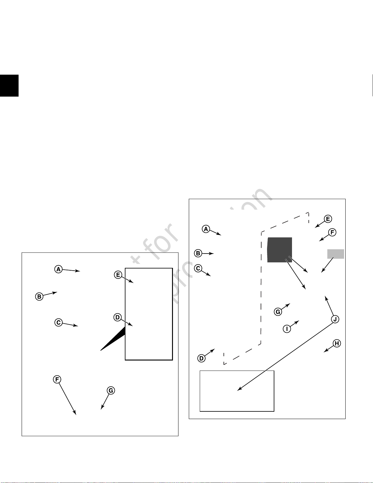
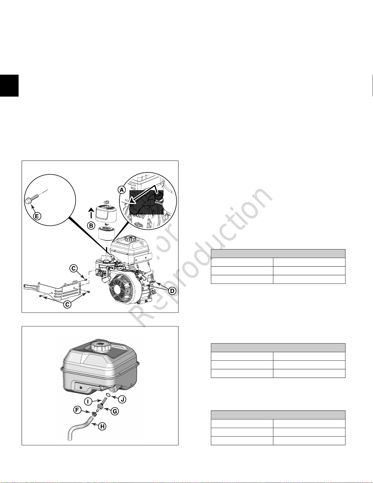
1. See Figure 4. Remove knob (A) to release air cleaner
cover (B).
2. Remove wing nut (C) to release air filter cartridge (D)
with foam pre-cleaner (E).
NOTE: Exercise care to keep dust and dirt out of
2
carburetor. Inadequate precautions can result in engine
damage.
3. Remove seal washer (F) from air cleaner base (G).
Inspect seal washer for damage or general
deterioration. Replace if necessary.
4. Remove foam pre-cleaner from air filter cartridge.
5. Gently tap air filter cartridge on a hard surface to loosen
dirt and debris. Carefully brush and/or vacuum air filter
cartridge as necessary.
10. Place air filter cartridge with foam pre-cleaner onto air
cleaner base. Install wing nut, but do not over-tighten.
11. Install air cleaner cover. Install knob, but do not
over-tighten.
Oil Bath Air Filter
1. See Figure 5. Remove knob (A) and flat washer (B) to
release air cleaner cover (C).
NOTE: Exercise care to keep dust and dirt out of
carburetor. Inadequate precautions can result in engine
damage.
2. Remove foam filter (D) from air cleaner cover.
3. Gently wash foam filter in warm, soapy water.
Thoroughly rinse with clean water and allow to air dry
completely.
NOTE: Use of pressurized air or solvents will damage
foam pre-cleaner and air filter cartridge.
6. Gently wash foam pre-cleaner in warm, soapy water.
Thoroughly rinse with clean water and allow to air dry
completely.
7. Carefully inspect foam pre-cleaner and air filter
cartridge. Replace parts if they cannot be adequately
cleaned or if any damage is observed.
8. Install foam pre-cleaner onto air filter cartridge.
9. Install seal washer onto air cleaner base.
4
NOTE: Use of pressurized air or solvents will damage
foam filter.
4. Carefully inspect foam filter. Replace if it cannot be
adequately cleaned or if any damage is observed.
5
12

Not for
Reproduction
5. Apply a small amount of clean SAE 30 engine oil to
foam filter. Gently squeeze foam filter until engine oil
is evenly distributed. Squeeze foam filter in a clean cloth
to remove excess oil.
6. Remove O-ring (E) and baffle screen (F) from bath bowl
(G).
7. Remove bath bowl from air cleaner base (H). Empty
used oil into an approved container.
8. Remove seal washer (I) from air cleaner base. Inspect
seal washer for damage or general deterioration.
Replace if necessary.
9. Wash bath bowl and air cleaner cover in warm, soapy
water. Wipe dry with a clean cloth.
10. Install seal washer and bath bowl onto air cleaner base.
11. Add clean SAE 30 engine oil to bath bowl until level is
even with horizontal line (J). Do not overfill.
12. Install baffle screen and O-ring onto bath bowl.
13. Install foam filter into air cleaner cover.
14. Install air cleaner cover.
15. Install flat washer and knob, but do not over-tighten.
16. Dispose of used oil at a proper waste disposal or
recycling center.
Foam Low Mount Air Filter
1. See Figure 6. Remove two hex flange screws (A) to
release air cleaner cover (B).
NOTE: Exercise care to keep dust and dirt out of
carburetor. Inadequate precautions can result in engine
damage.
2. Remove retainer (C) and foam filter (D) from air cleaner
cover.
3. Gently wash foam filter in warm, soapy water.
Thoroughly rinse with clean water. Squeeze foam filter
in a clean cloth until dry.
NOTE: Use of pressurized air or solvents will damage
foam filter.
4. Carefully inspect foam filter. Replace if it cannot be
adequately cleaned or if any damage is observed.
5. Saturate foam filter with clean engine oil. Gently
squeeze foam filter in a clean cloth to remove excess
oil.
6. Install foam filter and retainer into air cleaner cover.
7. Install air cleaner cover and start two hex flange screws.
Tighten screws to 9-12 lb-in (1-1.4 N-m).
Foam Large Panel Air Filter
1. See Figure 7. Disengage two retaining clips (A) to
release air cleaner cover (B) and foam filter (C).
NOTE: Exercise care to keep dust and dirt out of
carburetor. Inadequate precautions can result in engine
damage.
2. Gently wash foam filter in warm, soapy water.
Thoroughly rinse with clean water. Squeeze foam filter
in a clean cloth until dry.
NOTE: Use of pressurized air or solvents will damage
foam filter.
3. Carefully inspect foam filter. Replace if it cannot be
adequately cleaned or if any damage is observed.
4. Saturate foam filter with clean engine oil. Gently
squeeze foam filter in a clean cloth to remove excess
oil.
2
6
7
13
Not for
Reproduction
5. Install foam filter into air cleaner cover.
6. Install air cleaner cover and engage two retaining clips
to secure.
Paper Air Filter
1. See Figure 8. Loosen two hex flange screws (A) to
release air cleaner cover (B).
2
2. Remove pre-cleaner (C), if equipped, and filter (D).
3. Gently tap filter on a hard surface to loosen dirt and
debris. Carefully brush and/or vacuum as necessary.
NOTE: Use of pressurized air or solvents will damage
pre-cleaner and filter.
4. Gently wash pre-cleaner in warm, soapy water.
Thoroughly rinse with clean water and allow to air dry
completely. Do not oil pre-cleaner.
5. Carefully inspect pre-cleaner and filter. Replace parts
if they cannot be adequately cleaned or if any damage
is observed.
6. Install pre-cleaner and filter.
7. Install air cleaner cover and start two hex flange screws.
Tighten screws to 9-12 lb-in (1-1.4 N-m).
8
2. Clean area around and behind muffler. Proceed as
follows:
A. Remove all loose debris by hand.
B. Remove dust and dirt with a soft bristle brush and
a portable hand held vacuum.
C. Gently scrape away stubborn accumulations of dirt
and other deposits using a plastic putty knife or stiff
bristle brush.
D. Apply a light solvent to bristle brush to loosen and
remove grit and oily residue, if necessary.
3. Remove three hex flange screws to release wire guard
or stamped guard from muffler.
4. Inspect muffler for holes, split seams, cracked welds,
loose internal parts, corrosion, and other damage.
5. Inspect muffler tube and mounting flange for cracked
welds, breakage, and other damage.
6. Install three hex flange screws to fasten wire guard or
stamped guard to muffler. Tighten wire guard screws
to 30-50 lb-in (3.4-5.7 N-m). Tighten stamped guard
screws as follows.
Muffler Stamped Guard Screws
TorqueModels
80-110 lb-in (9-12.4 N-m)130G00, 131G00, 13R200
27-44 lb-in (3-5 N-m)13U100, 13U200
Clean/Inspect Muffler and Spark Arrester
NOTE: Avoid using high pressure compressed air, which
can force dirt and debris deeper into engine cavities and
crevices. Do not use a pressurized water spray as water
intrusion can contaminate both oil and fuel systems and
lead to corrosion.
1. Remove spark plug wire from spark plug terminal.
Secure spark plug wire to prevent contact with spark
plug terminal.
7. Verify that two hex nuts on muffler studs are tightened
as follows.
Muffler Stud Nuts
TorqueModels
80-110 lb-in (9-12.4 N-m)130G00, 131G00, 13R200
195-266 lb-in (22-30 N-m)13U100, 13U200
8. Inspect spark arrester for dirt, debris, and carbon
buildup. Proceed as follows:
A. Remove screw(s) to release spark arrester from
muffler/muffler guard. Note orientation of spark
arrester before removal.
B. Remove screening element from spark arrester.
C. Gently clean screening element with a stiff bristle
brush. If carbon buildup is present, soak or spray
with Carburetor Cleaner (Part No.'s 100041 or
100042). Blow dry from the inside-out with low
pressure compressed air. Exercise caution to avoid
bending or puncturing screening element. Replace
screening element if it cannot be adequately
cleaned or if any damage is observed.
D. Install screening element into spark arrester.
E. Orient spark arrester as noted before removal, and
install screw(s) to fasten to muffler/muffler guard.
Tighten screw(s) as follows.
14
Not for
Reproduction
Stamped/Wire Guard Spark Arrester Screw(s)
TorqueModels
71-124 lb-in (8-14 N-m)130G00, 131G00, 13R200
27-44 lb-in (3-5 N-m)13U100, 13U200
NOTE: Verify that vent hole (D) of oil fill/vent plug is
facing outside.
9. Dispose of used oil at a proper waste disposal or
recycling center.
NOTE: Spark arrester is installed in either the 9 o'clock
or the optional 6 o'clock position.
Change 6:1 Gear Reduction Oil (If Equipped)
1. Remove spark plug wire from spark plug terminal.
Secure spark plug wire to prevent unintentional contact
with spark plug terminal.
2. Place engine on a flat, level surface.
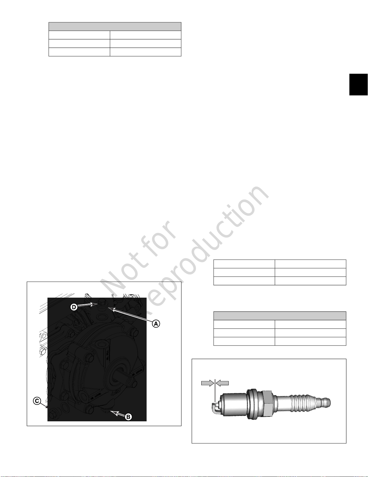
3. See Figure 9. Remove oil fill/vent plug (A) with sealing
washer from the gear case cover.
4. Remove oil drain plug (B) with sealing washer and drain
oil into an approved container.
5. Install oil drain plug with sealing washer and tighten to
180-210 lb-in (20.3-23.7 N-m).
6. Remove oil level plug (C) with sealing washer.
7. Slowly add the appropriate oil into the oil fill hole until
oil begins to run out of the oil level hole (approximately
4 ounces).
• Use SAE 80W-90 above 40° F (10° C)
• Use SAE 10W-30 below 40° F (10° C)
8. Install oil level plug with sealing washer. Install oil
fill/vent plug with copper washer. Tighten each plug to
180-210 lb-in (20.3-23.7 N-m).
9
Clean/Gap/Replace Spark Plug
NOTE: Spark plugs have different thread lengths and heat
ranges. Always use the specified replacement spark plug
or engine damage can occur.
NOTE: Some localities require use of a special resistor type
spark plug to suppress ignition noise. If the engine was
originally equipped with a resistor type spark plug, be sure
to use the same replacement spark plug.
1. Remove spark plug wire from spark plug terminal.
2. Thoroughly clean area around spark plug to keep dirt
and debris out of combustion chamber.
3. Remove spark plug from cylinder head using the 5/8
inch Spark Plug Wrench (Part No. 19576S).
4. Check condition of threads in cylinder head. If
necessary, soften deposits with penetrating oil and
clean out with a thread chaser.
5. Clean spark plug using a wire brush and commercial
solvent. Do not bead blast spark plug. Obtain new spark
plug if electrode is pitted or burned, or if porcelain is
cracked.
6. See Figure 10. Using a feeler gauge, verify spark plug
gap is as follows. If necessary, adjust gap by carefully
bending ground electrode.
Spark Plug GapModels
0.027-0.033 in (0.69-0.83 mm)130G00, 131G00, 13R200
0.028-0.035 in (0.70-0.90 mm)13U100, 13U200
7. Finger tighten spark plug into cylinder head, and then
tighten as follows.
2
Spark Plug
TorqueModels
140-200 lb-in (15.8-22.6 N-m)130G00, 131G00, 13R200
230-319 lb-in (26-36 N-m)13U100, 13U200
10
15
Not for
Reproduction
8. Install spark plug wire onto spark plug terminal.
Clean/Replace In-Tank Fuel Filter
1. Start and run engine until fuel tank is empty.
2. See Figure 11. Remove spark plug wire from spark plug
terminal (A). Secure spark plug wire to prevent
unintentional contact with spark plug terminal.
2
3. Remove air cleaner cover and air filter (B). See
Clean/Replace Air Filter and Pre-Cleaner
4. Remove plastic knob from throttle control lever.
5. If equipped, remove hex flange screw to release high
oil fill tube flange from control panel trim.
6. Remove three hex flange screws (C) to release control
panel trim from fuel tank. Disengage control panel trim
from slot in air cleaner base.
in this section.
11
7. Remove two hex flange nuts (D) from fuel tank studs.
8. On opposite side of fuel tank, remove hex flange screw
(E) to release fuel tank from crankcase flange.
NOTE: For best access to screw, move throttle control
lever left to the FAST position and use a 8 mm socket
with extension.
NOTE: Exercise care to avoid dropping screw between
engine and blower housing. A dropped screw may be
caught by the flywheel magnet where further
disassembly would be required to retrieve it.
9. See Figure 12. Squeeze tangs and move hose clamp
(F) away from fuel filter fitting (G).
10. Remove hose (H) from fuel filter fitting. For best results,
use Fuel Hose Remover (Part No. 19620).
11. Using hex, remove fuel filter fitting from fuel tank.
12. Unthread fuel filter (I) and remove O-ring (J) from fuel
filter fitting.
13. Inspect fuel filter for dirt and debris. Clean or replace
as necessary.
14. Inspect O-ring for cuts, tears, or general deterioration.
Replace as necessary.
15. Install O-ring onto fuel filter fitting. Verify O-ring is fully
seated in groove.
16. Thread fuel filter into fuel filter fitting.
17. Install fuel filter fitting into fuel tank. Tighten fitting as
follows.
12
Fuel Filter Fitting
TorqueModels
60-70 lb-in (6.8-7.9 N-m)130G00, 131G00, 13R200
62-71 lb-in (7-8 N-m)13U100, 13U200
18. Inspect hose for cuts, nicks, cracks, or general
deterioration. Replace hose if necessary.
19. Place fuel tank onto engine.
20. Install hex flange screw to fasten fuel tank to crankcase
flange. Tighten screw as follows.
Fuel Tank Screw
TorqueModels
75-95 lb-in (8.5-10.7 N-m)130G00, 131G00, 13R200
71-124 lb-in (8-14 N-m)13U100, 13U200
21. On opposite side, install two hex flange nuts onto fuel
tank studs. Alternately tighten nuts as follows.
Fuel Tank Nuts
TorqueModels
90-110 lb-in (10.2-12.4 N-m)130G00, 131G00, 13R200
71-124 lb-in (8-14 N-m)13U100, 13U200
16
Not for
Reproduction
22. Install hose with clamp onto fuel filter fitting. Squeeze
tangs and move hose clamp about 1/8 inch (3 mm)
from end of hose with tangs pointing upward for best
access.
23. Start three hex flange screws to fasten control panel
trim to fuel tank. Engage end of control panel trim in
slot of air cleaner base. Starting with screw above
rewind starter, tighten screws to 20-40 lb-in (2.3-4.5
N-m).
24. If equipped, install hex flange screw to fasten high oil
fill tube flange to control panel trim. Tighten screw to
5-15 lb-in (0.6-1.6 N-m).
25. Install plastic knob onto throttle control lever.
26. Install air filter and air cleaner cover. See
Air Filter and Pre-Cleaner
27. Install spark plug wire onto spark plug terminal.
in this section.
Clean/Replace
Clean Carburetor Sediment Bowl
WARNING
13
2
Wrap shop towel around sediment bowl to catch any
fuel leakage. Gasoline is extremely flammable and
highly explosive. Inadequate safety precautions can
result in death or serious injury. Always observe the
following precautions when working with fuel system
components:
• Wear proper eye protection.
• Be sure there is no open flame or potential ignition
sources in the area.
• Keep a dry chemical fire extinguisher on hand in
case of emergencies.
• Thoroughly wipe up any spilt fuel immediately.
• Collect any fuel and/or shop towels in approved
containers and dispose of properly.
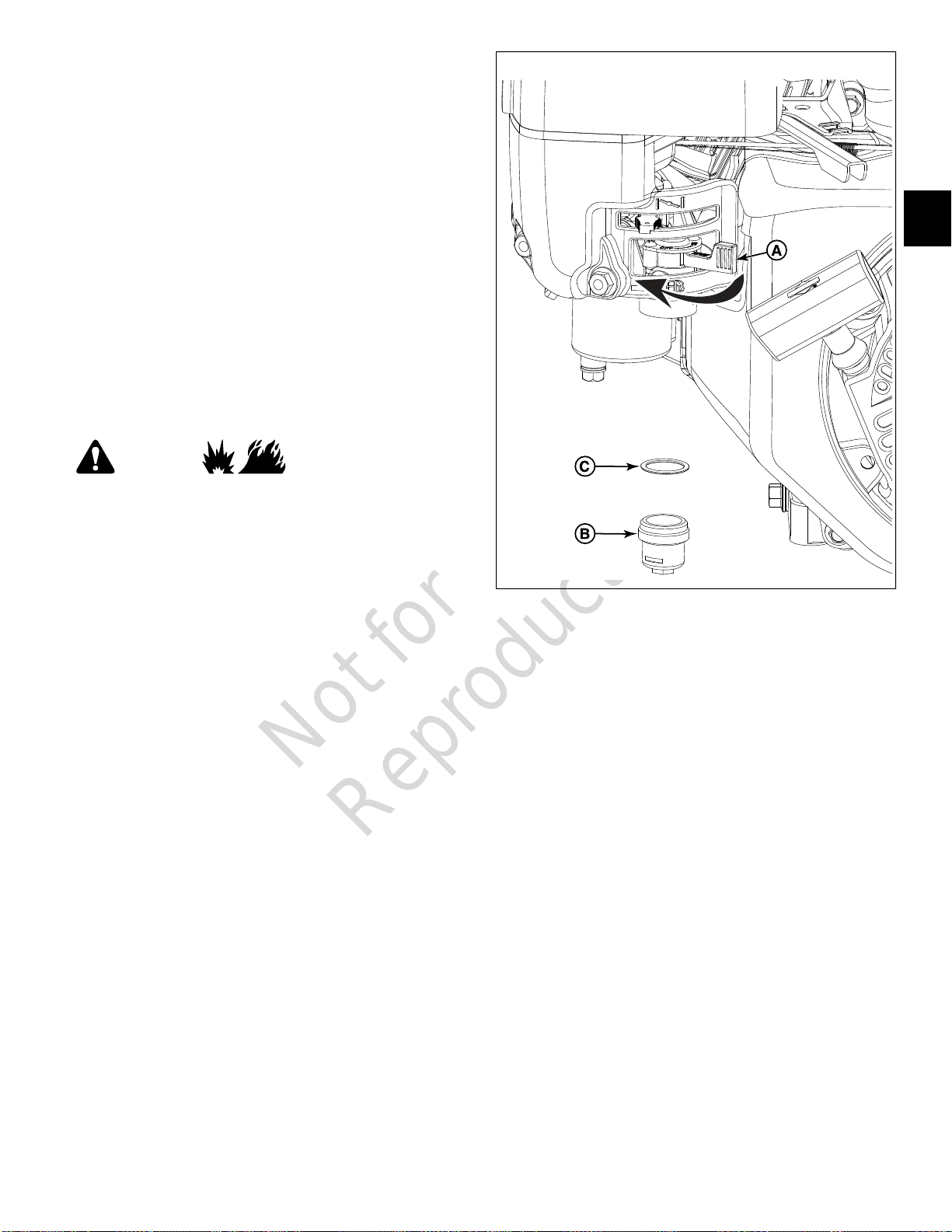
1. Start and run engine until fuel tank is empty.
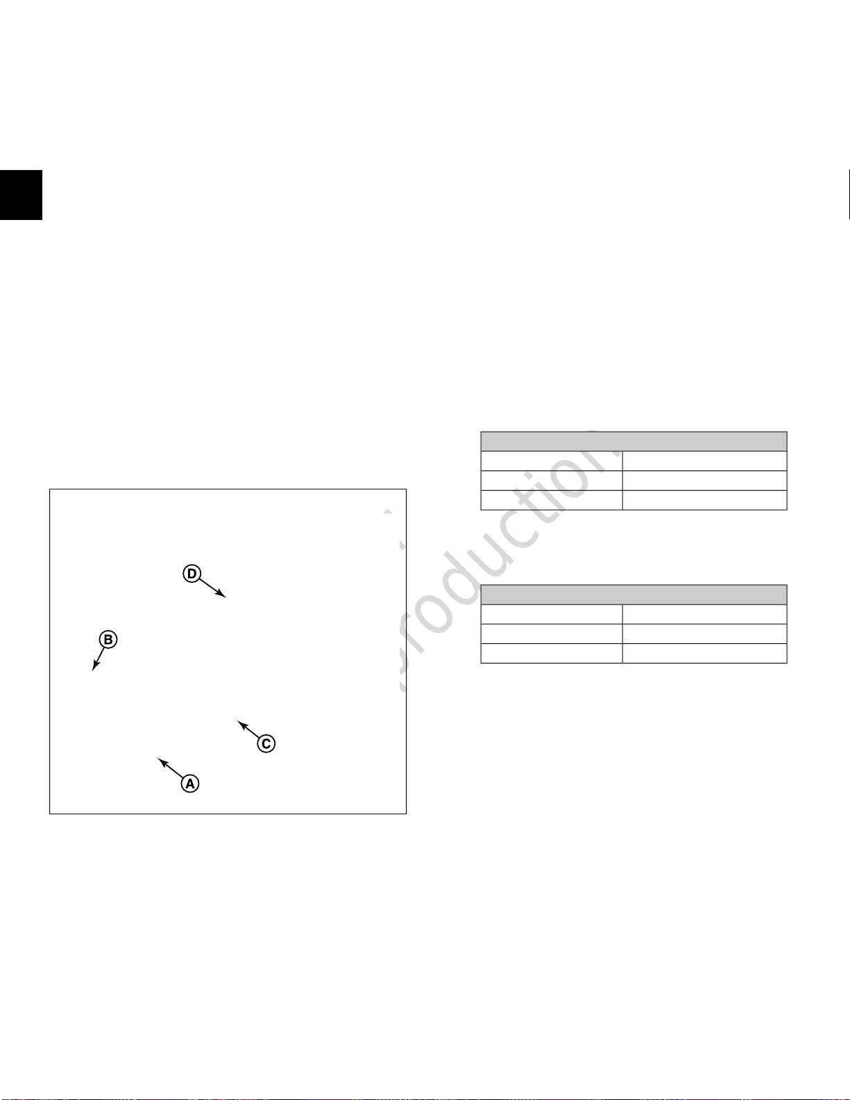
2. See Figure 13. Position fuel valve (A) to OFF.
3. Remove spark plug wire from spark plug terminal.
Secure spark plug wire to prevent unintentional contact
with spark plug terminal.
4. Remove sediment bowl (B) with O-ring (C) from
carburetor body.
5. Thoroughly clean sediment bowl of sediment, gum or
varnish deposits. Use Carburetor Cleaner (Part No.'s
100041 or 100042), if necessary.
6. Inspect O-ring for cuts, tears, or general deterioration.
Replace as necessary.
7. Install sediment bowl with O-ring. Tighten sediment
bowl to 49-80 lb-in (5.5-9 N-m).
8. Install spark plug wire onto spark plug terminal.
Clean Air Cooling System
NOTE: Avoid using high pressure compressed air, which
can force dirt and debris deeper into engine cavities and
crevices. Do not use a pressurized water spray as water
intrusion can contaminate both oil and fuel systems and
lead to corrosion.
1. Remove spark plug wire from spark plug terminal.
Secure spark plug wire to prevent unintentional contact
with spark plug terminal.
2. Remove three hex flange screws to release rewind
starter from blower housing.
NOTE: Note orientation of the rewind starter before
removal.
3. Remove three hex flange screws to release cylinder
heat shield from crankcase and cylinder head.
4. Clean cylinder cooling fins, the inside of the rewind
starter, and the flywheel fan as follows:
A. Remove all loose debris by hand.
B. Remove dust and dirt with a soft bristle brush and
a portable hand held vacuum.
17
Not for
Reproduction
C. Gently scrape away stubborn accumulations of dirt
and other deposits using a plastic putty knife or stiff
bristle brush.
D. Apply a light solvent to bristle brush to loosen and
remove grit and oily residue, if necessary.
5. Install three hex flange screws to fasten cylinder heat
shield to crankcase and cylinder head.
14
2
NOTE: Hex flange screw to engine base captures both
heat shield and blower housing.
6. Orient rewind starter as noted before removal.
NOTE: Rewind starter may be installed in the 2 o'clock,
8 o'clock, 10 o'clock, or 12 o'clock positions.
7. Loosely install three hex flange screws to fasten rewind
starter to blower housing.
NOTE: To ensure that pawls evenly engage flywheel
starter cup, pull starter rope, tighten hex flange screws
until snug, and then release starter rope.
8. Alternately tighten three hex flange screws as follows.
Cylinder Heat Shield Screws
TorqueModels
40-60 lb-in (4.5-6.8 N-m)130G00, 131G00, 13R200
71-124 lb-in (8-14 N-m)13U100, 13U200
Rewind Starter Screws
TorqueModels
25-35 lb-in (2.8-4 N-m)130G00, 131G00, 13R200
71-89 lb-in (8-10 N-m)13U100, 13U200
Check/Adjust Valve Clearance
NOTE: For best results, check valve clearance with the
engine cold.
1. Remove spark plug wire from spark plug terminal.
2. Thoroughly clean area around spark plug to keep dust
and dirt out of the combustion chamber.
3. Remove spark plug from cylinder head using the 5/8
inch Spark Plug Wrench (Part No. 19576S).
4. Remove four hex flange screws to release valve cover.
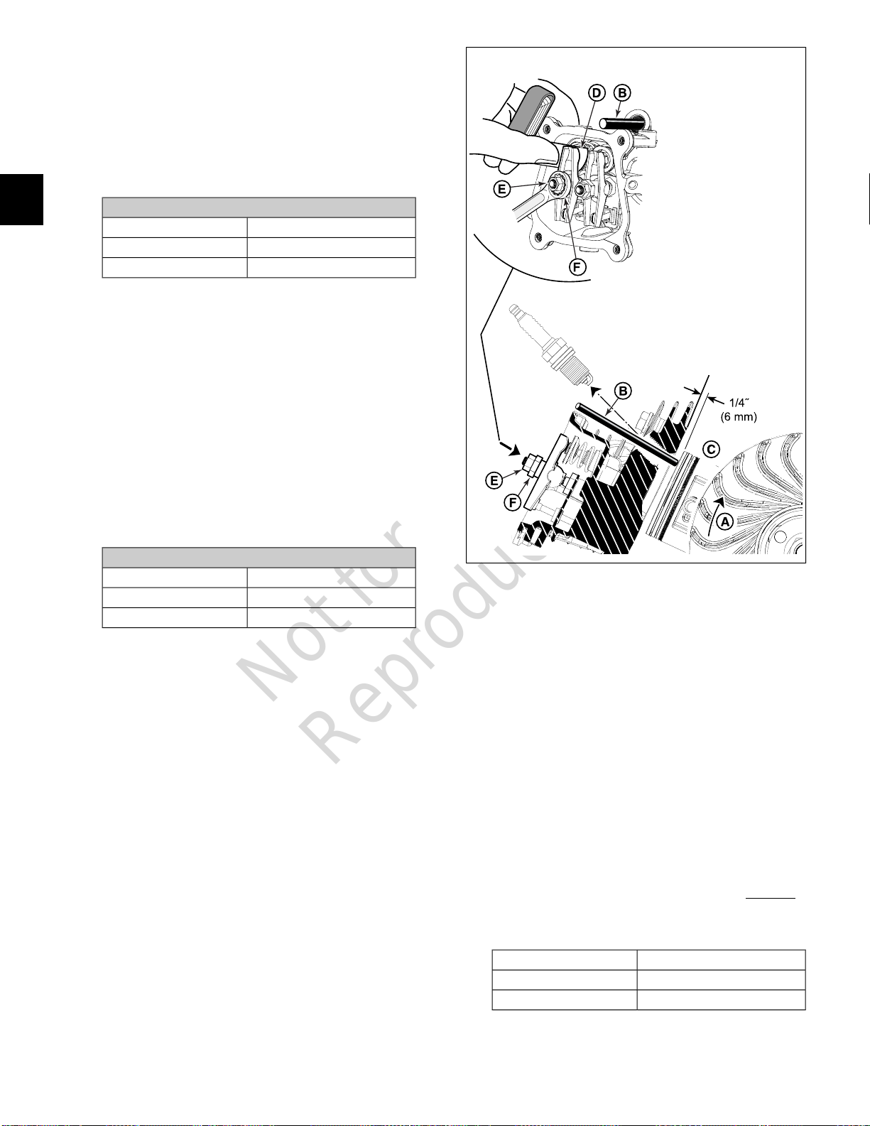
5. Move piston 1/4 inch (6 mm) past Top Dead Center
(TDC) of the compression stroke. Proceed as follows:
A. See Figure 14. While rotating flywheel end of
crankshaft (A) by hand in the direction of engine
rotation, watch the rocker arms to determine the
action of the valves. After the exhaust valve closes,
the intake valve begins to open.
B. When the intake valve closes (so that both valves
are closed with the rocker arms loose), insert a
wooden dowel (B) through the spark plug hole until
seated at the top of the piston (C).
C. Rotate engine in the same direction until the piston
pushes the wooden dowel to its highest point. This
is TDC of the compression stroke.
D. Place a mark on the wooden dowel that is even
with the machined surface at the top of the spark
plug hole. Make a second mark 1/4 inch (6 mm)
above the first.
E. Rotate engine in the same direction until the second
mark on the wooden dowel is even with the
machined surface at the top of the spark plug hole.
Remove wooden dowel.
6. Insert feeler gauge between rocker arm and exhaust
valve stem (D). Verify that exhaust valve clearance is
as follows.
Exhaust Valve ClearanceModels
0.006-0.008 in (0.15-0.20 mm)130G00, 131G00, 13R200
0.005-0.007 in (0.13-0.18 mm)13U100, 13U200
18

Not for
Reproduction
7. If adjustment is necessary, proceed as follows:
A. Loosen locknut (E) and turn rocker ball nut (F) as
necessary.
B. Holding rocker ball nut to prevent rotation, tighten
locknut as follows.
Rocker Ball Locknut
TorqueModels
60-80 lb-in (6.8-9 N-m)130G00, 131G00,
13R200
71-124 lb-in (8-14 N-m)13U100, 13U200
C. Check valve clearance again to verify that rocker
ball did not move when locknut was tightened.
8. Insert feeler gauge between rocker arm and intake valve
stem. Verify that intake valve clearance is as follows.
If adjustment is necessary, see step 7.
Intake Valve ClearanceModels
0.004-0.006 in (0.10-0.15 mm)130G00, 131G00, 13R200
0.005-0.007 in (0.13-0.18 mm)13U100, 13U200
2
9. Remove old gasket material from valve cover and
cylinder head flanges. Gasket material left on sealing
surfaces will cause leaks.
10. Install new valve cover gasket into valve cover.
11. Start four hex flange screws to fasten valve cover to
cylinder head. Using a crosswise pattern. alternately
tighten screws as follows.
Valve Cover Screws
TorqueModels
70-90 lb-in (7.9-10.2 N-m)130G00, 131G00, 13R200
71-124 lb-in (8-14 N-m)13U100, 13U200
12. Install spark plug into cylinder head and finger tighten
until snug. Tighten spark plug as follows.
Spark Plug
TorqueModels
140-200 lb-in (15.8-22.6 N-m)130G00, 131G00, 13R200
230-319 lb-in (26-36 N-m)13U100, 13U200
13. Install spark plug wire onto spark plug terminal.
19

Not for
Reproduction
2
20

Not for
Reproduction
SECTION 3 – TROUBLESHOOTING/SPECIAL TOOLS
TROUBLESHOOTING - - - - - - - - - - - - - - - - - - - - - - - - - - - - - - - - - - - - - - - - - - - - - - - - - - - - - - - - - - - - - - - - - - - - 22
Check Ignition - - - - - - - - - - - - - - - - - - - - - - - - - - - - - - - - - - - - - - - - - - - - - - - - - - - - - - - - - - - - - - - - - - - - - - - 22
Check Carburetion - - - - - - - - - - - - - - - - - - - - - - - - - - - - - - - - - - - - - - - - - - - - - - - - - - - - - - - - - - - - - - - - - - - - 23
Check Compression - - - - - - - - - - - - - - - - - - - - - - - - - - - - - - - - - - - - - - - - - - - - - - - - - - - - - - - - - - - - - - - - - - - 23
Check Low Oil Sensor System - - - - - - - - - - - - - - - - - - - - - - - - - - - - - - - - - - - - - - - - - - - - - - - - - - - - - - - - - - - 24
Check Breather Valve - - - - - - - - - - - - - - - - - - - - - - - - - - - - - - - - - - - - - - - - - - - - - - - - - - - - - - - - - - - - - - - - - 24
SPECIAL TOOLS - - - - - - - - - - - - - - - - - - - - - - - - - - - - - - - - - - - - - - - - - - - - - - - - - - - - - - - - - - - - - - - - - - - - - - - 25
3
21
Not for
Reproduction
TROUBLESHOOTING
General Complaints
Most complaints concerning engine operation include one
or more of the following:
• Will not start
• Hard starting
• Lack of power
• Runs rough
3
• Vibration
• Overheating
• High oil consumption
Equipment Check
What often appears to be a problem with the engine may
actually be the result of faulty equipment.
No Start or Hard Start
• Loose belt or blade
• Cranking under load
• Misadjusted controls
• Improperly operating low oil sensor system
Engine Will Not Stop
• Equipment stop switch not functioning
• Engine ground wire damaged or disconnected
Check Ignition
1. Move to step 2 if engine does not start. If engine runs,
but misses, move to step 9.
Engine Does Not Start
2. Verify that engine oil level is within the cross hatch
pattern on the dipstick.
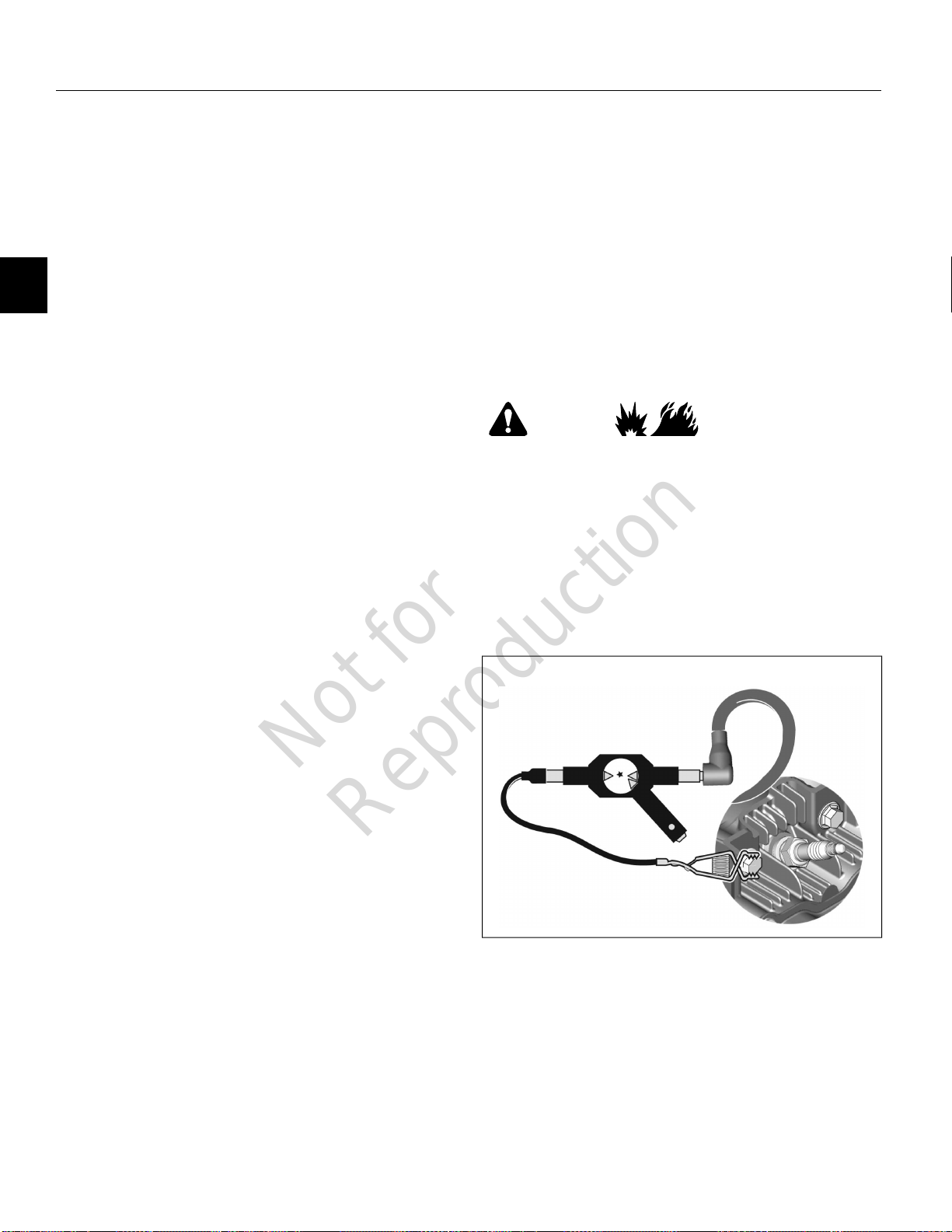
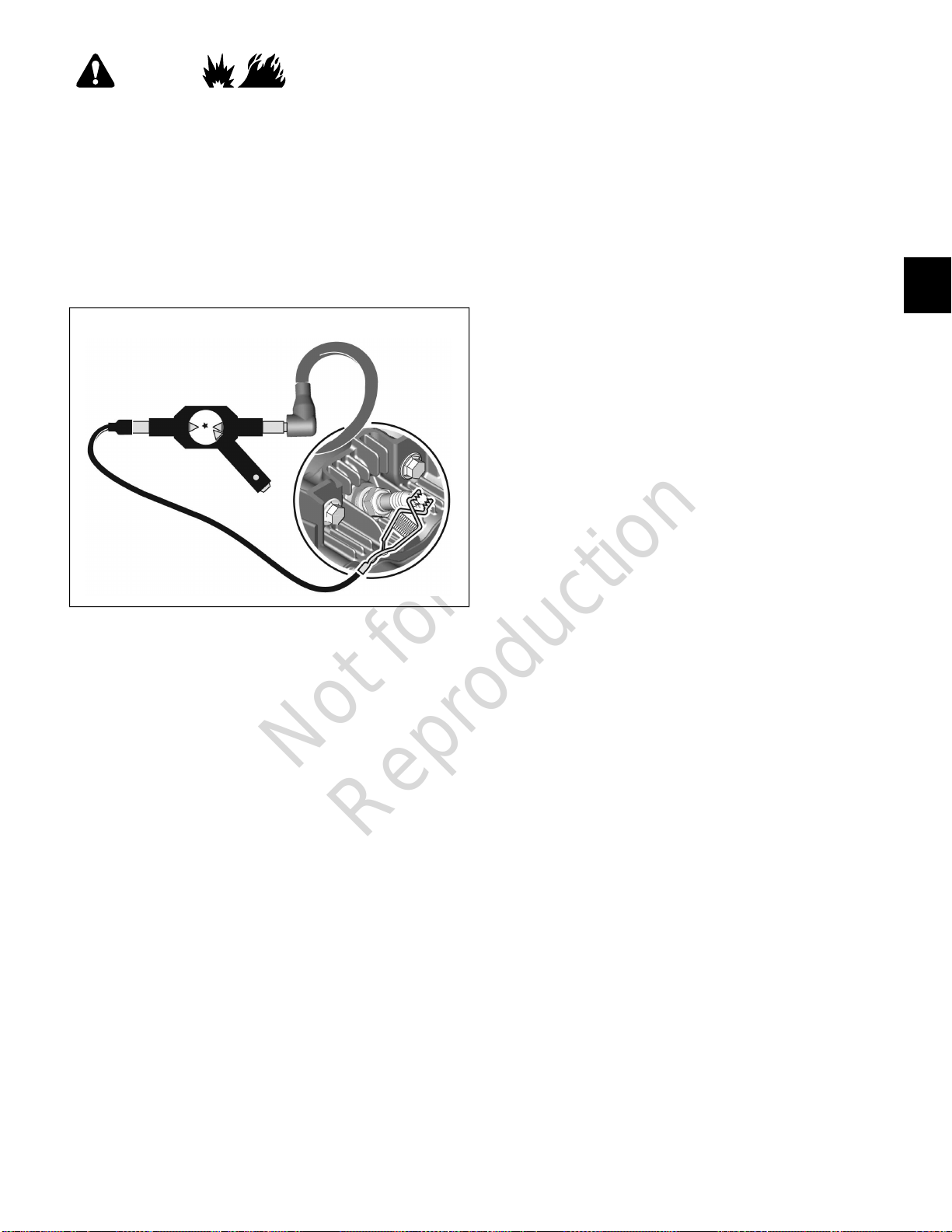
3. Obtain Ignition Tester (Part No. 19368).
4. Remove spark plug wire from spark plug terminal.
5. See Figure 15. Install free end of spark plug wire onto
inline tester prong. Install tester alligator clip onto good
engine ground.
WARNING
Be sure there is no fuel or fuel vapors present which,
if spark ignited, can cause a fire or explosion resulting
in death or serious injury.
6. Move throttle control lever to FAST.
7. Pull rewind starter rope (or activate electric starter, if
equipped). If spark jumps the tester gap, the ignition
system is functioning satisfactorily.
8. If spark is not present, move to step 15.
Vibration
• Bent cutter blades
• Loose spindles and couplings
• Bent/broken deck or weldments
• Bent crankshaft
• Loose equipment mounting bolts
• Damaged or worn belts and pulleys
• Out of balance impeller
Power Loss
• Bind or drag in moving parts of equipment
• Grass build-up under deck
• No lubrication in equipment gear box
• Excessive belt tension
Systems Check
Once equipment sources are ruled out, most symptoms can
be traced to one or more of the following. Perform these
checks in the order listed.
1. Ignition
2. Carburetion
3. Compression
15
Engine Runs But Misses
9. Obtain Ignition Tester (Part No. 19368).
10. Remove spark plug wire from spark plug terminal.
11. See Figure 16. Install free end of spark plug wire onto
inline tester prong. Install tester alligator clip onto spark
plug terminal.
22
Not for
Reproduction
WARNING
Be sure there is no fuel or fuel vapors present which,
if spark ignited, can cause a fire or explosion resulting
in death or serious injury.
12. Move throttle control lever to FAST.
13. Pull rewind starter rope (or activate electric starter, if
equipped). If spark jumps the tester gap, install a new
spark plug.
14. If spark is not present, move to step 15.
16
• Plugged air cleaner
• Fouled spark plug
6. A dry spark plug may indicate:
• Leaking carburetor or intake manifold gaskets
• Gummy or dirty carburetor, fuel filter, fuel lines, or
fuel tank
• Carburetor float needle valve stuck closed
NOTE: To determine if the fuel is getting to the
combustion chamber through the carburetor, remove
the spark plug and pour a small quantity of gasoline
through the spark plug hole. Install the spark plug and
crank the engine. If the engine fires a few times and
then stops, look for the same conditions as those listed
for a dry spark plug.
Check Compression
Engine Does Not Start
1. Obtain Leakdown Tester (Part No. 19545).
2. Follow the instructions provided with the tester to check
the sealing capabilities of compression components.
3
15. If spark is not present, look for:
• Improperly operating low oil sensor system
• Shorted equipment or engine stop switch wire
• Incorrect armature air gap
• Armature failure
Check Carburetion
1. Verify that fuel tank has an ample supply of fresh, clean
gasoline.
2. Verify that fuel valve is positioned to ON, if equipped,
and that fuel flows freely through the fuel line. If fuel
flow is slow or fails to flow, check for plugged fuel cap
vent, fuel line restriction, or plugged fuel filter.
3. Verify that throttle and choke controls are clean and
properly adjusted.
4. If engine cranks, but will not start, remove and inspect
the spark plug.
5. A wet spark plug may indicate:
NOTE: Any air leaks at the tester connections and
fittings will adversely affect test results.
3. The sound of air flow:
• between the cylinder and cylinder head indicates
the cylinder head gasket is leaking.
• from the carburetor indicates air is leaking past the
intake valve and valve seat.
• from the exhaust system indicates air is leaking
past the exhaust valve and valve seat.
• from the breather tube or oil fill dipstick tube
indicates air is leaking past the piston rings.
4. The likely causes of poor compression are:
• Loose cylinder head screws
• Damaged cylinder head gasket
• Burned valves, burned valve seats, and/or loose
valve seats
• Insufficient tappet clearance
• Warped cylinder head
• Warped valve stems
• Worn cylinder bore and/or piston rings
• Broken connecting rod
• Over choking
• Excessively rich fuel mixture
• Water in fuel
• Carburetor float needle valve stuck open
23
Not for
Reproduction
Check Low Oil Sensor System
Engine Does Not Start
1. Verify that engine oil level is within the cross hatch
pattern on the dipstick.
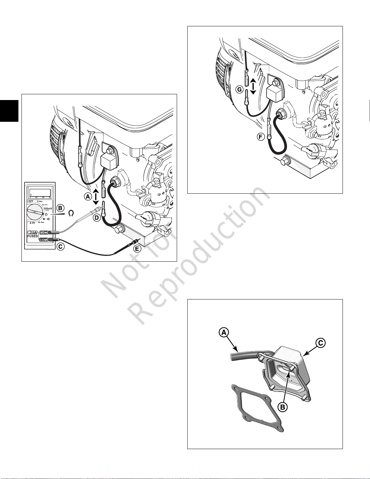
2. See Figure 17. If engine oil level is satisfactory,
disconnect one-place wire connector between oil sensor
module and oil sensor in crankcase (A).
17
3
18
3. Obtain Digital Multimeter (Part No. 19602), and set to
read ohms (B).
4. Insert RED meter test lead into V Ω receptacle, and
BLACK meter test lead into COM receptacle (C).
5. Connect red meter test lead to oil sensor wire (D), and
black meter test lead to engine base (E).
6. Measure resistance. Replace sensor in crankcase if
continuity is obtained. Proceed to next step if meter
reads infinity.
7. See Figure 18. Connect one-place wire connector
between oil sensor module and oil sensor in crankcase
(F).
8. Disconnect one-place wire connector between oil sensor
module and armature coil (G).
9. Start engine. Verify that oil sensor module wire is not
touching ground.
10. Replace oil sensor module if engine starts. If engine
does not start, check oil sensor module wiring for shorts
to ground.
Check Breather Valve
Engine Does Not Start
1. See Figure 19. Gently blow air into breather hose (A)
to verify that there is no air flow through valve.
2. Apply vacuum or draw air out through breather hose to
verify that air flows freely through valve.
3. If air flow has no resistance when blowing or is restricted
under vacuum, the breather valve (B) is faulty. Replace
the valve cover (C).
19
24
 Loading...