

Page 1
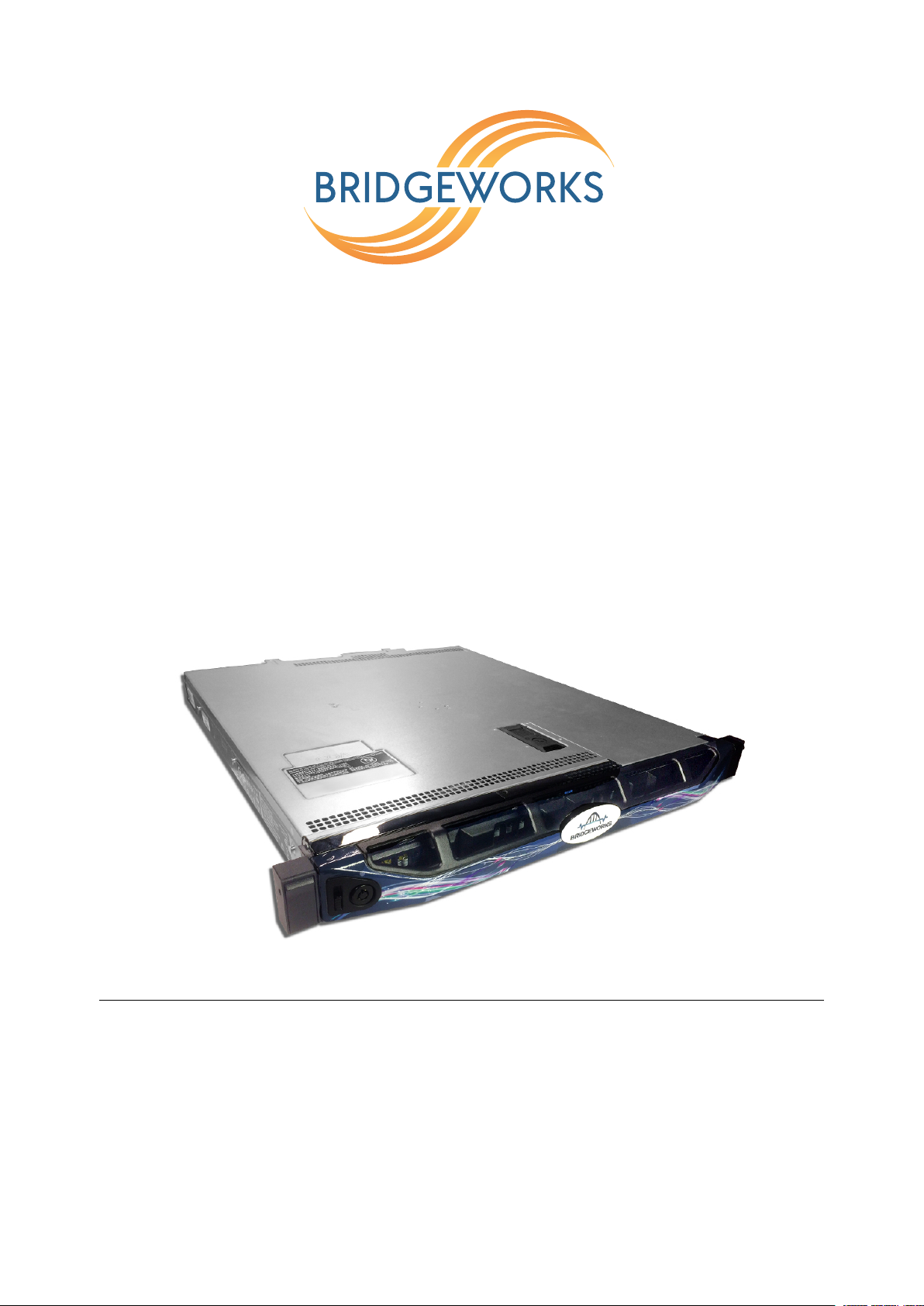
Appliance a003
Hardware Manual
Eli-v5.02.153
Bridgeworks
Unit 1, Aero Centre, Ampress Lane,
Ampress Park, Lymington,
Hampshire SO41 8QF
Tel: +44 (0) 1590 615 444
Email: [email protected]
Page 2

Warning
The Bridgeworks Appliance contains no user serviceable components. Only an Authorised Service
Centre should carry out any servicing or repairs. Unauthorised repairs or modifications will
immediately void your warranty.
Before you start
There are a number of additional pieces of equipment you will require for the successful installation
of your Appliance depending on the feature cards installed:
Ethernet Cable
You will require at least one good quality cable of suitable length to go between your network access
point and the Appliance. This should be marked as certified to Cat 5e and have an RJ45 style
connector at the Appliance end.
10Gb Ethernet Cable
Depending on the configuration you have purchased, you will require at least one cable from either:
LC Multi-mode Optical Fibre Cable (SFP+)
• Multi-mode Optical Fibre 50/125 OM3 or OM4 Patch Cable (LC), up to 300 meters.
Or Copper Interface Cable (SFP+)
•
SFP+ Direct Attach Copper (DAC) Twin-Ax interface cable (passive), up to 7 meters. Bridgeworks
Part Number 017/034.
Or 10GBASE-T Category 6/6a Cable (RJ45)
• Category 6 certified cable with an RJ45 style connector, up to 55 meters.
• Category 6a certified cable with an RJ45 style connector, up to 100 meters.
6Gb SAS Cable
The Appliance uses a Mini-SAS style connector, also known as an iPASS or SFF-8088 connector,
with 4 phys per wide port. You will require a SAS cable that supports this connector at the Appliance
end and the type of connector your peripheral device supports at the other end.
Fibre Channel Cable
You will require at least one Multi-mode Optical Fibre 50/125 OM3/OM4 Patch Cable (LC) of suitable
length to go between your Appliance and device, host, or Fibre Channel switch.
If you are in any doubt, please contact your reseller for assistance.
2
Page 3

Table of Contents
1 Introduction 4
1.1 Manual Layout . . . . . . . . . . . . . . . . . . . . . . . . . . . . . . . . . . . . . . . 4
1.2 Safety Notices . . . . . . . . . . . . . . . . . . . . . . . . . . . . . . . . . . . . . . . 5
2 Installing the Appliance 7
2.1 Appliance Configuration . . . . . . . . . . . . . . . . . . . . . . . . . . . . . . . . . . 7
2.2 Connecting the Ethernet Interface . . . . . . . . . . . . . . . . . . . . . . . . . . . . 7
2.3 Connecting the 10Gb Ethernet Cables . . . . . . . . . . . . . . . . . . . . . . . . . . 8
2.3.1 Using a LC Multi-mode Optical Fibre Cable (SFP+) . . . . . . . . . . . . . . . 8
2.3.2 Using a Copper Interface Cable (SFP+) . . . . . . . . . . . . . . . . . . . . . 9
2.3.3 Using a 10GBASE-T Category 6 or 6a Cable (RJ45) . . . . . . . . . . . . . . 10
2.4 Connecting the 6Gb SAS cables . . . . . . . . . . . . . . . . . . . . . . . . . . . . . 10
2.5 Connecting the Fibre Channel Interface . . . . . . . . . . . . . . . . . . . . . . . . . 11
2.6 Connecting the Power Supply . . . . . . . . . . . . . . . . . . . . . . . . . . . . . . . 12
Appendix A Visual Indicators 14
A.1 Ethernet . . . . . . . . . . . . . . . . . . . . . . . . . . . . . . . . . . . . . . . . . . . 14
Appendix B Technical Specifications 15
3
Page 4
1 Introduction
1.1 Manual Layout
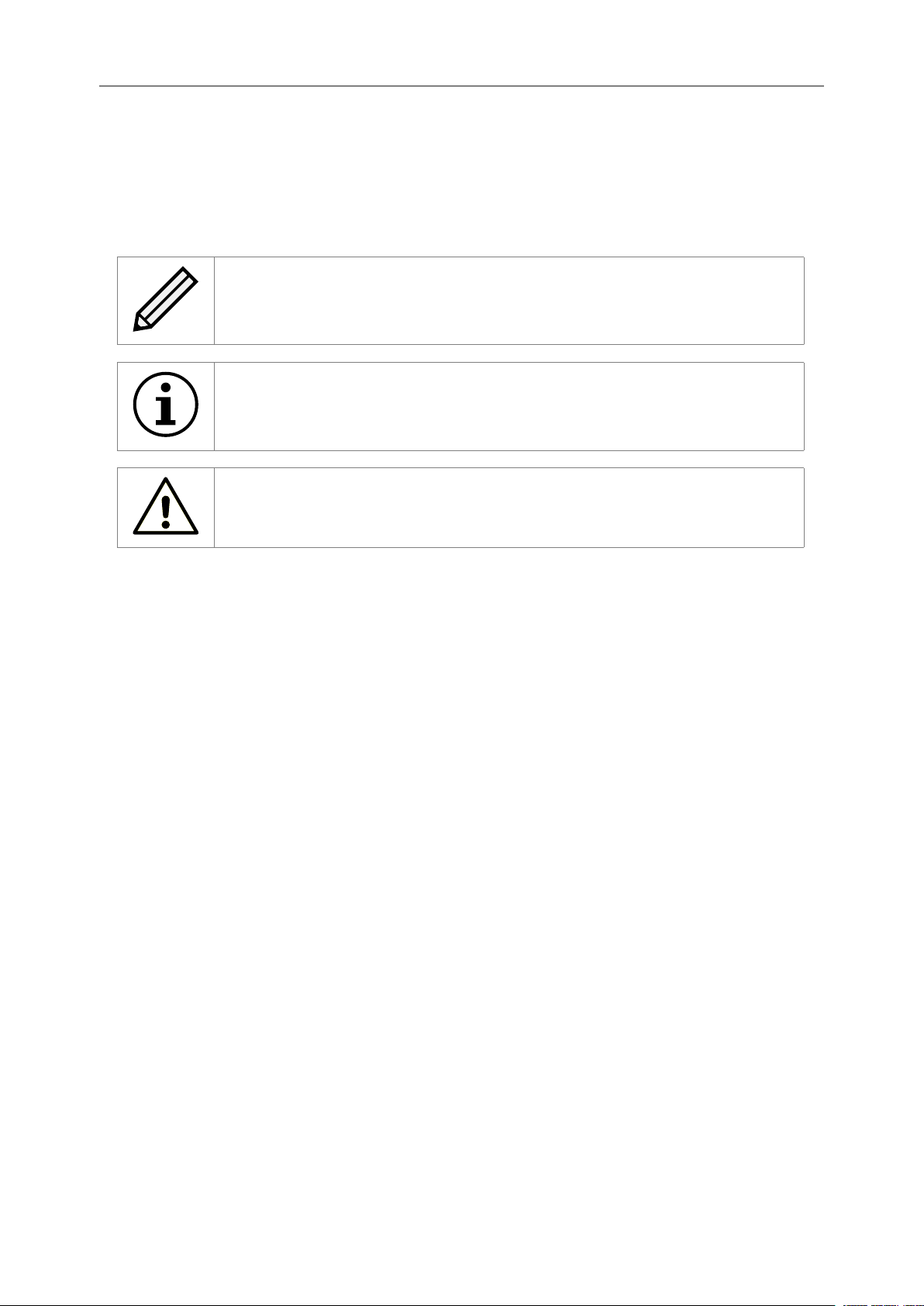
Throughout the manual, symbols will be used to quickly identify different pieces of information.
This icon represents a note of interest about a step or section of information.
This icon represents an important piece of information.
This icon represents a warning. Care must be taken and the warning should
be read thoroughly.
4
Page 5
1.2 Safety Notices
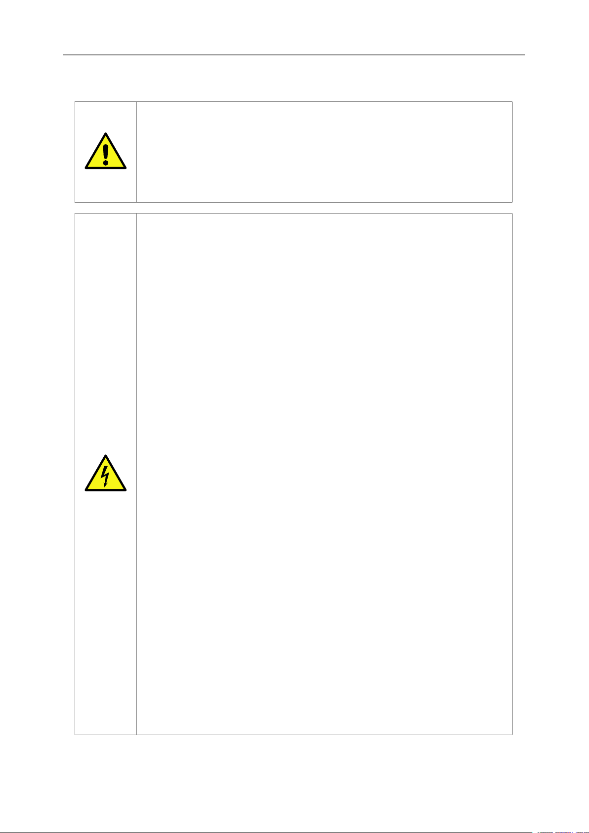
This device should only be installed by suitably trained personnel.
Protection provided by the equipment may be impaired if used in a manner
not specified by the manufacturer.
Do not block the enclosure’s vents. Air enters from the front and is exhausted
out the back of the device.
This device requires a connection to AC power in order to operate. Before
using the device, please read the instructions carefully, in order to use the
device correctly and safely. For the installation instructions, refer to Chapter 2:
Installing the Appliance.
Class I Equipment. This equipment must be earthed. The power plug must
be connected to a properly wired earthed ground socket outlet. An improperly
wired socket outlet could expose hazardous voltages on accessible metal
parts.
Do not attempt to service the equipment yourself. Doing so will void the
warranty and may damage the system. This unit may contain hazardous
voltages and should only be opened by a trained and qualified technician.
To prevent electric shock, do not remove the cover. Contact an authorised
service center to perform any servicing inside the Appliance, the user should
not attempt to service any parts inside the unit themselves.
The power cord is used as a disconnection device, be aware after
disconnection of the AC power some internal components may retain charge
still and represent a shock hazard.
Do not use the equipment where it can get wet. Protect equipment from liquid
intrusion. If your equipment gets wet, disconnect power to the equipment and
to any attached devices. If the Appliance is connected to an electrical outlet,
turn off the AC power at the circuit breaker before attempting to remove the
power cables from the electrical outlet. Disconnect any attached devices.
Use only approved power cables(s) rated for the equipment. The voltage and
current rating of the cable should be greater than the ratings marked on the
equipment.
If the incorrect cables for your geographical area have been supplied with
your unit please contact your supplier.
The mains plug to the rear of the unit is used as the power disconnect device;
please ensure that this is kept clear from any obstruction and is visible at all
times.
To prevent electrical shock hazard, disconnect the power cable from the
electrical outlet before relocating the system.
5
Page 6

Class 1 Laser Product: Certain models will use a Small Form factor Pluggable
(SFP) Transceiver module for connection to an optical network. These devices
may use a Class 1 Laser device—it is important that you do not stare into the
Laser beam.
6
Page 7
2 Installing the Appliance
The following are the basic steps to installing the Appliance:
• Connecting the Ethernet Interface
• Connecting the 10Gb Ethernet Cables*
• Connecting the 6Gb SAS cables*
• Connecting the Fibre Channel Interface*
• Connecting the Power Supply
*If an appropriate feature card is installed.
2.1 Appliance Configuration
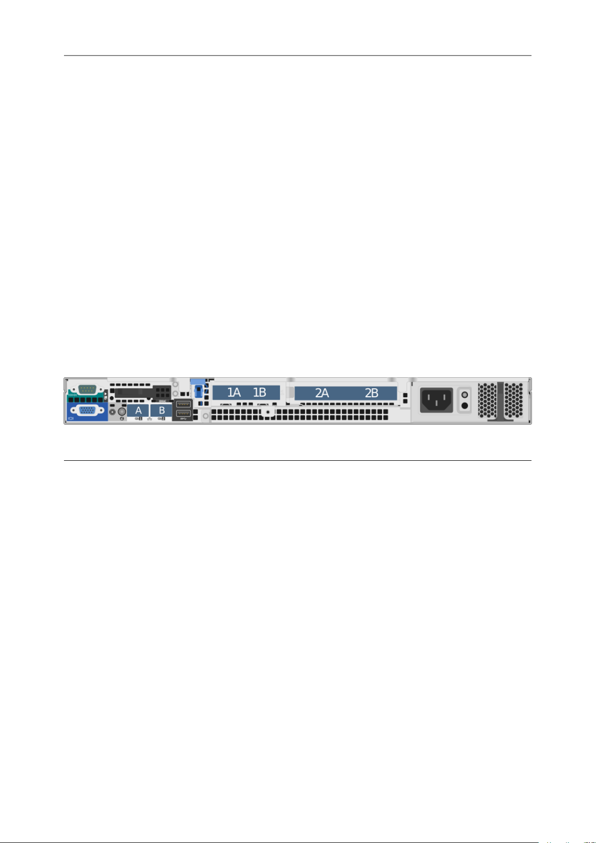
The following image is a representation of the back of the Appliance and can be used to identify the
positions of the various feature cards available on your product.
Product
EFC102200 Management Management iSCSI Target FC Initiator
ESAS102800 Management Management iSCSI Target SAS Initiator
FCE102200 Management Management FC Target iSCSI Initiator
FCSAS102800 Management Management FC Target SAS Initiator
WANrockIT 100 Management WAN * -
WANrockIT 200 Management WAN * -
PORTrockIT 100 Management WAN * -
PORTrockIT 200 Management Management * *
*Feature card chosen at time of purchase.
Onboard PortAOnboard PortBSlot 1 (1A/1B) Slot 2 (2A/2B)
2.2 Connecting the Ethernet Interface
The onboard Ethernet interfaces on the Appliance can be used on the following network configurations:
• 10BASE-T
• 100BASE-T
• 1000BASE-T (Gigabit)
7
Page 8
It is not necessary to specify which network type you are connected to, as the Appliance will
automatically select the correct network speed.
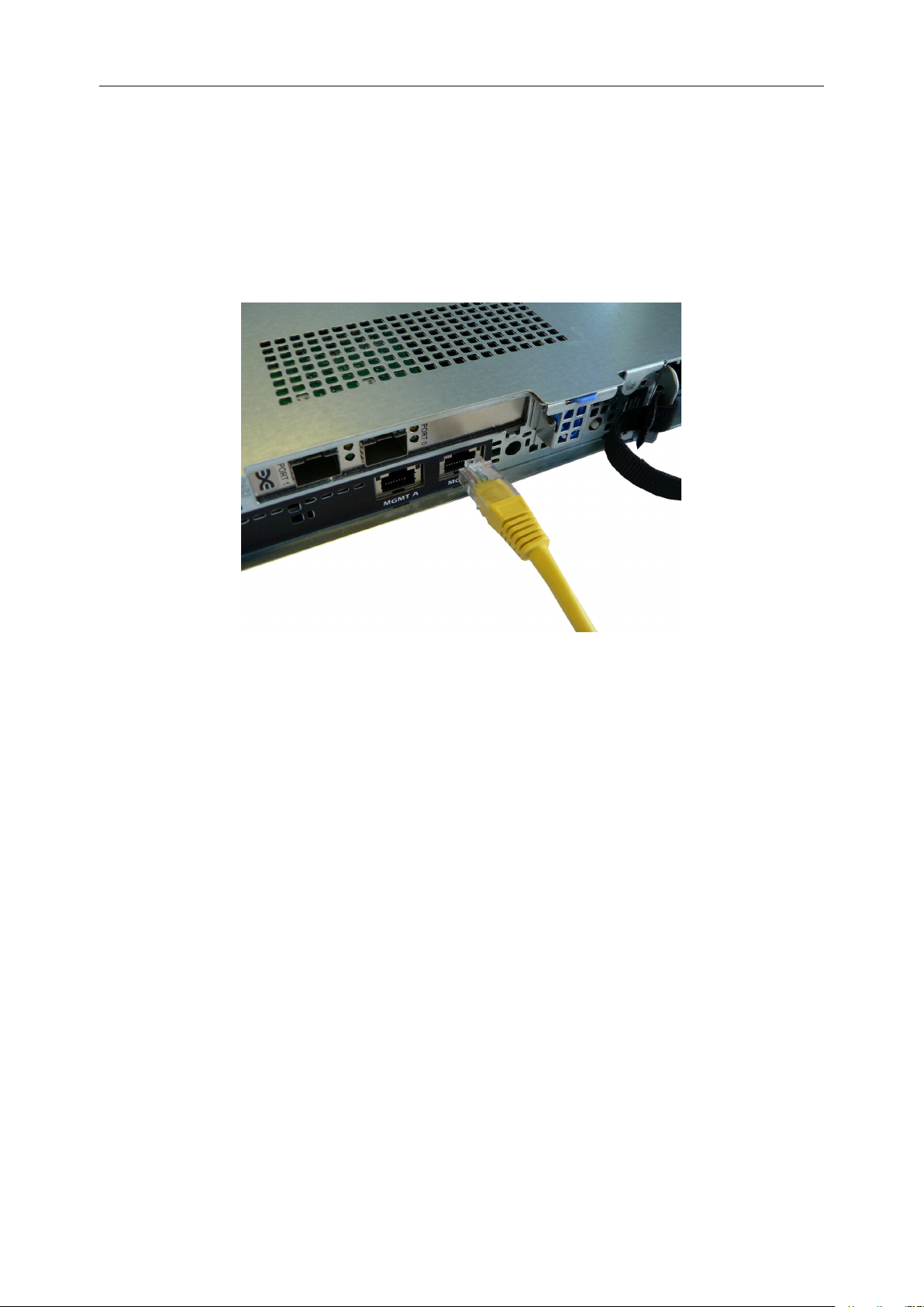
The onboard Ethernet interfaces can be found at the back of the Appliance and are used for either
Management or WAN. See Section 2.1: Appliance Configuration to see interface assignments.
To connect an onboard interface, insert a Cat 5e cable (or better) into it as shown in the following
image. When the plug is in the correct position a “click” should be heard. The other end of the
cable should be connected to a network.
Rear Panel of the Appliance Showing Ethernet Cable Connections
2.3 Connecting the 10Gb Ethernet Cables
Depending on the configuration you have purchased, either one of the following cables will be
required for your product.
• LC Multi-mode Optical Fibre Cable (SFP+)
• Copper Interface Cable (SFP+)
• 10GBASE-T Category 6 or 6a Cable (RJ45)
2.3.1 Using a LC Multi-mode Optical Fibre Cable (SFP+)
If you have purchased a 10GBASE-SR feature card, connections up to 300 metres are supported
using OM3 or OM4 grade Multi-mode Optical Fibre 50/125 using LC connectors.
To connect the Appliance to an Ethernet network or directly to a device, insert one or two SFPs into
the unit.
8
Page 9
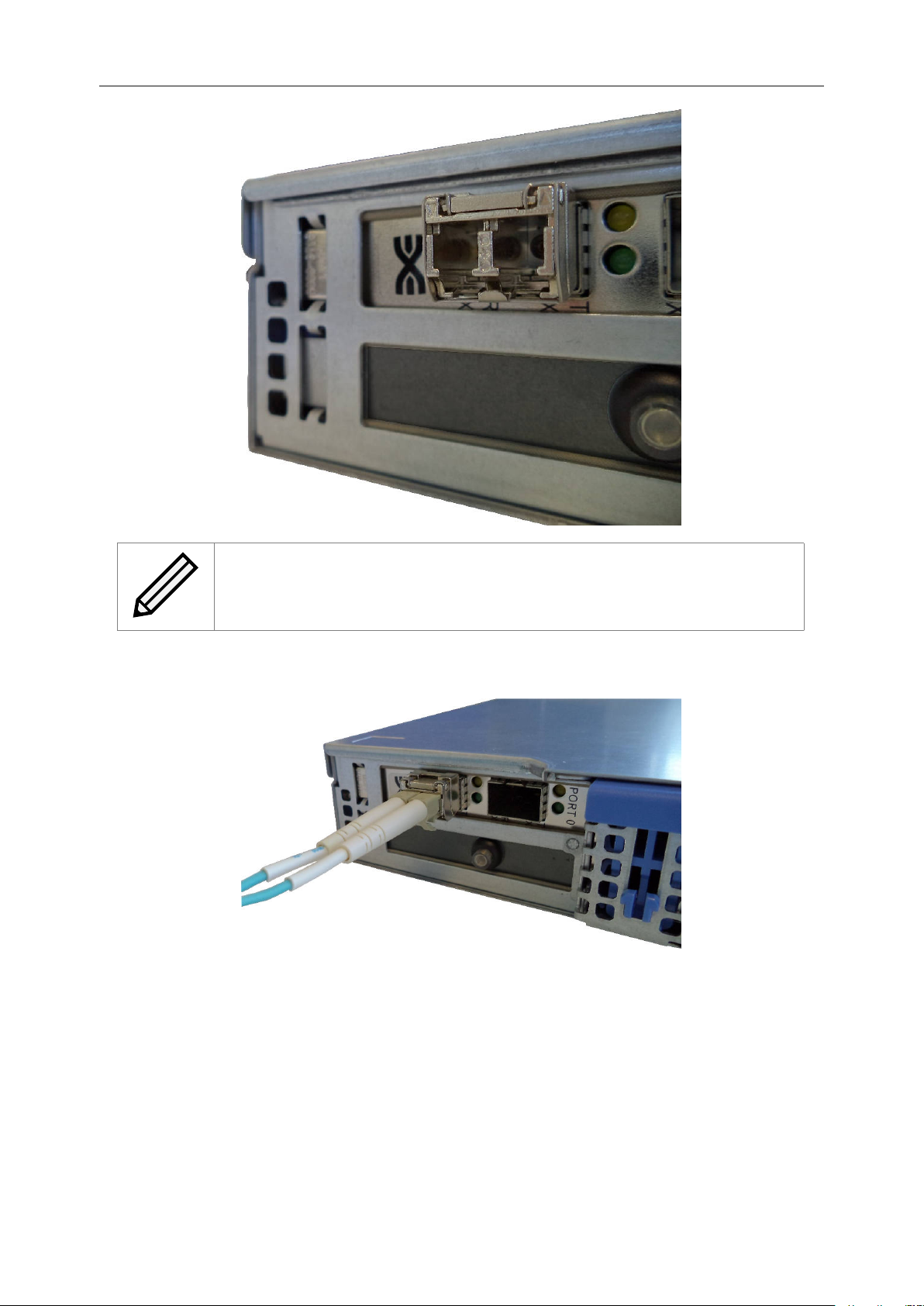
Note: SFPs will come pre-installed when a 10GBASE-SR feature card has
been purchased with your configuration.
Insert the multi-mode cables in to the SFP as shown below. When the plug is in the correct position
a “click” should be heard.
2.3.2 Using a Copper Interface Cable (SFP+)
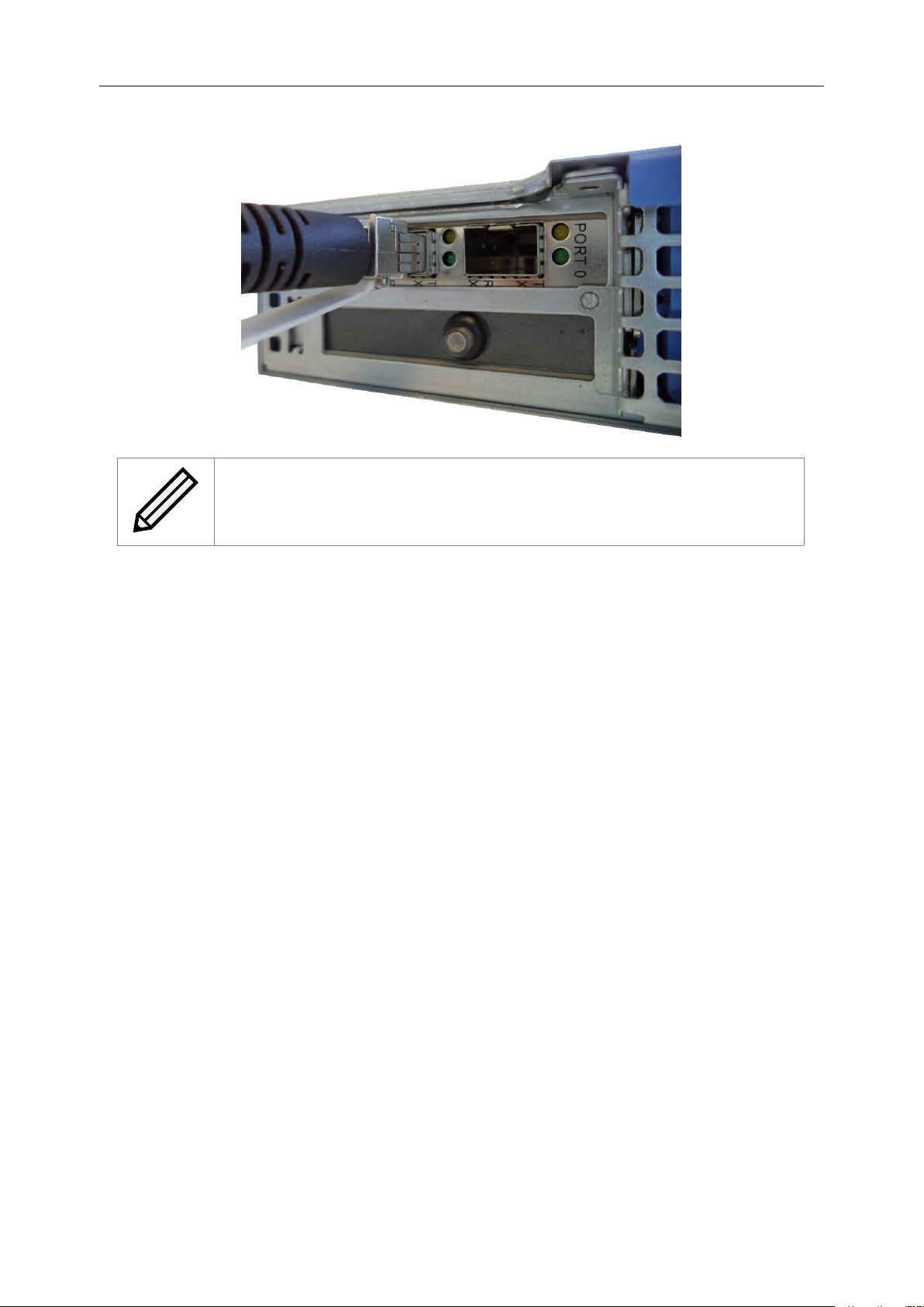
If you are using a copper based solution, an SFP+ Direct Attach Copper (DAC) Twin-Ax interface
cable must be used; the maximum supported length of which is a 7 meter passive cable.
To connect the Appliance directly to a device, insert one or two SFP+ cables in to the connector as
shown below. When the plug is connected a “click” should be heard.
9
Page 10
Note: Speeds other than 10Gb/sec may not be supported by your 10Gb NIC.
2.3.3 Using a 10GBASE-T Category 6 or 6a Cable (RJ45)
If you are using a copper based solution using the RJ45 connector, a Category 6 or 6a Ethernet
cable is required, with a maximum length of 55 meters for Category 6 and 100 meters for Category
6a.
To connect the Appliance to an Ethernet network or directly to a device, connect one side of the
Category 6 Ethernet cable into a RJ45 port located on a 10 Gigabit Ethernet card at the back of the
unit. When the plug is in the correct position, a “click” should be heard. Connect the other side of
the cable to your Ethernet network or device.
2.4 Connecting the 6Gb SAS cables
The SAS bus on the Appliance is capable of running at speeds of up to 6Gbits/s. However, devices
that operate at slower speeds (1.5 Gbits/s and 3Gbits/s) can still be connected to this SAS bus. The
Appliance will automatically negotiate with these devices to obtain their optimal operating speed
upon power up. Each SAS wide port can support up to 4 phys.
Connect the SAS cable(s) to the Appliance as shown below, ensuring that connector is the correct
way up.
10
Page 11
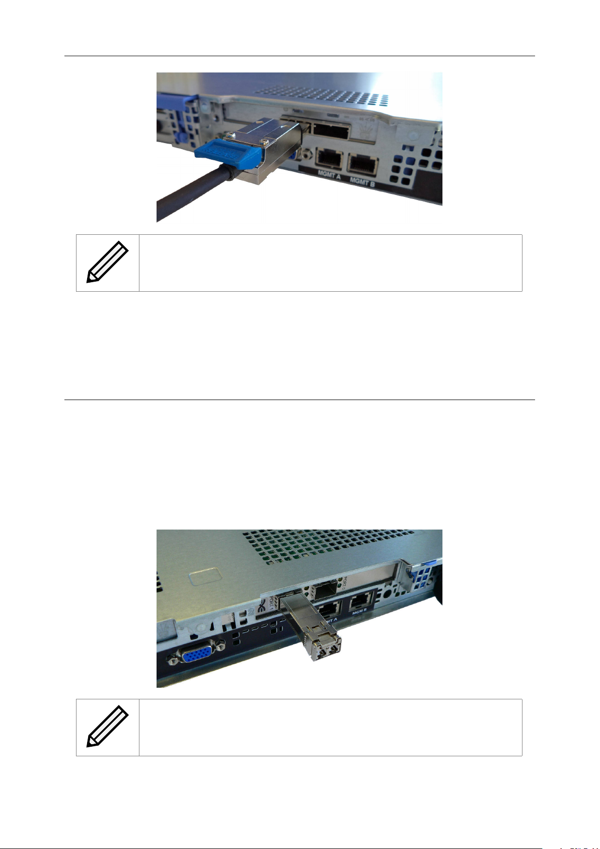
Note: Each SAS wide port supports 4 independent SAS channels or phys.
You can use either wide port as the initial port.
2.5 Connecting the Fibre Channel Interface
The supported link speeds are dependent on the Fibre Channel card that is installed. The supported
link speeds for each card are listed below.
Fibre Channel Card Speed Supported Link Speeds
8Gb 2Gb, 4Gb, 8Gb
16Gb 4Gb, 8Gb, 16Gb
It is not necessary to specify which link speed you are using as the Appliance will automatically
negotiate the best speed when first powered up.
To connect to the Fibre Channel network, a Small Form-factor Pluggable (SFP) interface module
must be inserted into the SFP receptacle at the back of the Appliance as shown in the following
image.
Note: Only use SFP transceivers that meet or exceed the following standards:
EU: IEC/EN 60825-1, North America: FCC, CDRH
11
Page 12
Note: SFPs will come pre-installed when a Fibre Channel card has been
purchased with your configuration.
The following multi-mode optical fibre cables are supported up to the lengths given:
Fibre Channel Speed OM1 OM2 OM3
2Gb/s 150m 150m 150m
4Gb/s 70m 150m 150m
8Gb/s 50m 150m
16GB/s 100m
Connect your host to a target port and your device (such as a tape drive) to an initiator port.
Note: By default WANrockIT units have the left hand port (Port A) as the
target port and the right hand port (Port B) as the initiator port.
When the multi-mode cables are inserted in to the SFP, a “click” should be heard.
2.6 Connecting the Power Supply
Important: Before connecting the power cord, ensure that the wall or rack
plug is removed or is switched off.
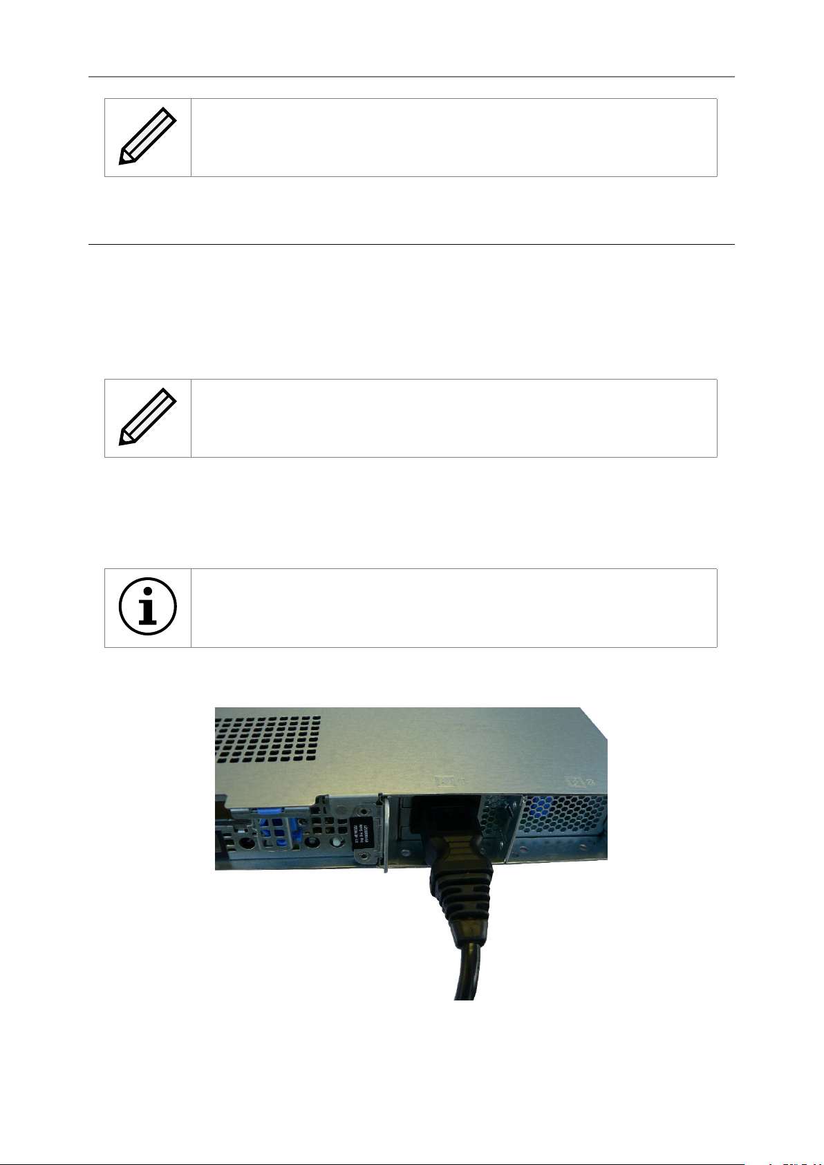
Connect the power supply to the rear of the Appliance as shown below and turn on the power from
the wall socket.
12
Page 13

Note: Before powering up the Appliance, ensure that all peripherals and
interfaces are properly connected and are powered up.
To turn on the Appliance push the switch on the front , as shown below.
The first version of the Appliance has a power switch on the back, as shown below.
Whenever the Appliance is powered on, the switch will be illuminated in the colour green and system
fans will be easily heard.
13
Page 14
A Visual Indicators
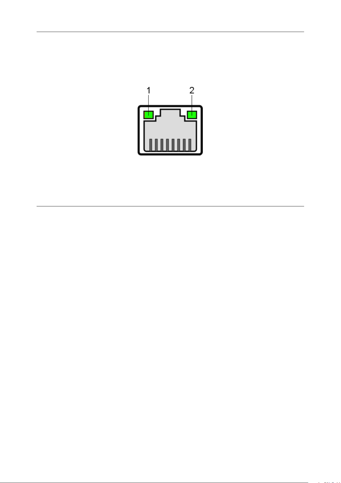
A.1 Ethernet
1. Link indicator
2. Activity indicator
Link Activity Description
Off Off Not connected.
Amber Connected at less than maximum speed.
Green Connected at maximum speed.
Flashing Green Data is being sent or received.
14
Page 15

B Technical Specifications
Physical
Form Factor 19001U rack mount
Overall Depth 551.3mm
Rack Depth Required 495.0mm
Height 42.8mm
Width 482.4mm with rack latches
Weight 8.77kg at maximum configuration
Recommended minimum
clearance for cooling
Electrical
Input voltage 100–240V
Frequency 50–60Hz
Input current 4.0–2.0A
Maximum power consumption
Environmental
Operational temperature 10◦C to 35◦C
Non-operational temperature -40◦C to 65◦C
Humidity 10–80% non-condensing
Onboard Management
Interface
No. of interfaces 1–2
Physical RJ45 (8P8C)
Speed Auto-sensing 10 / 100 / 1000Mb/s
Standards IPv4, NTP, SNMP, DHCP
Onboard WAN Interface
No. of interfaces 0–1
Physical RJ45 (8P8C)
Speed Auto-sensing 10 / 100 / 1000Mb/s.
Feature Cards
No. of feature cards Up to 2
Supported feature cards WAN 1GbE
WAN 1GbE Feature Card
No. of interfaces 2
Physical RJ45 (8P8C)
Speed Auto-sensing 10 / 100 / 1000Mb/s.
WAN 10GbE Feature Card
100mm on front and rear faces
250W approx.
WAN 10GbE
iSCSI 1GbE
iSCSI 10GbE
Fibre Channel 8Gb
SAS 6Gb
15
Page 16

No. of interfaces 2
Physical SFP+ Twin-Ax, 10GBase-SR Laser LC, RJ45 (8P8C)
Speed Auto-sensing 1000 / 10000Mb/s.
iSCSI 1GbE Feature Card
No. of interfaces 1-2
Physical RJ45 (8P8C)
Speed Auto-sensing 10 / 100 / 1000Mb/s
Error Recovery ERL0, ERL1, ERL2
Standards IPv4, iSCSI, iSNS, CHAP, DHCP
iSCSI 10GbE Feature Card
No. of interfaces 2
Physical SFP+ Twin-Ax, 10GBASE-SR Laser LC, 10GBASE-T RJ45
(8P8C)
Speed Auto-sensing 1000 / 10000Mb/s
Error Recovery ERL0, ERL1, ERL2
Standards IPv4, iSCSI, iSNS, CHAP, DHCP
Fibre Channel 8Gb Feature
Card
No. of interfaces 2
Physical SFP mini GBIC
Speed Auto-sensing 2 / 4 / 8Gb/s
Standards FC-AL, FC-PLDA, FC-TAPE, FC-PH, FC-FLA, FCP-SCSI,
FC-FS
Topology NL_port, FL_port, N_port, F_port
SAS 6Gb Feature Card
No. of wide ports 2
Physical SFF-8088 External Mini-SAS
Phys per wide port 4
Speed Auto-sensing 1.5 / 3 / 6Gb/s
Protocol SAS 2.0
Visual Indicators
Power
Network Link, Activity & Speed
Fibre Channel Link & Speed
SAS Link & Activity
16
 Loading...