

Page 1

PC Based Network Video Recorder
BRC-64
User Manual
Quality Service Group
Page 2

Product name: PC Based Network Video Recorder (BRC-64)
Release Date: 2013/05
Manual Revision: V4.1
Web site: www.brickcom.com
Email: [email protected]
©2013 Brickcom Corporation. All Rights Reserved
0000154
Page 3

Table of Contents
Package Contents............................................................................................4
Overview........................................................................................................5
Software Installation........................................................................................8
BRC64 Installation...................................................................................... 8
EasyConfig Installation...............................................................................11
Launch EasyConfig.........................................................................................15
Start With BRC64......................................................................................... 21
Supported Sites.......................................................................................28
Main Window......................................................................................... 29
Camera List...................................................................................... 30
Setting............................................................................................. 30
PTZ Setting....................................................................................... 31
Other Buttons.................................................................................... 32
Configure BRC64...........................................................................................34
Live View...............................................................................................35
Setting..................................................................................................37
Add/Remove a Site............................................................................37
Camera............................................................................................38
Sequence.........................................................................................45
Storage........................................................................................... 45
Video Wall....................................................................................... 47
NVS Setting..................................................................................... 49
Remote liveview............................................................................... 50
Remote Playback.............................................................................. 51
System........................................................................................... 55
Alarm.................................................................................................... 56
How to configure & trigger alarm notifications...................................... 56
Schedule Recording................................................................................. 71
Playback............................................................................................... 77
Log...................................................................................................... 87
Snapshot................................................................................................88
E-map................................................................................................... 89
Account Manage..................................................................................... 92
Lock...................................................................................................... 87
Hot-Key.................................................................................................. 98
Watchdog............................................................................................... 99
Page 4
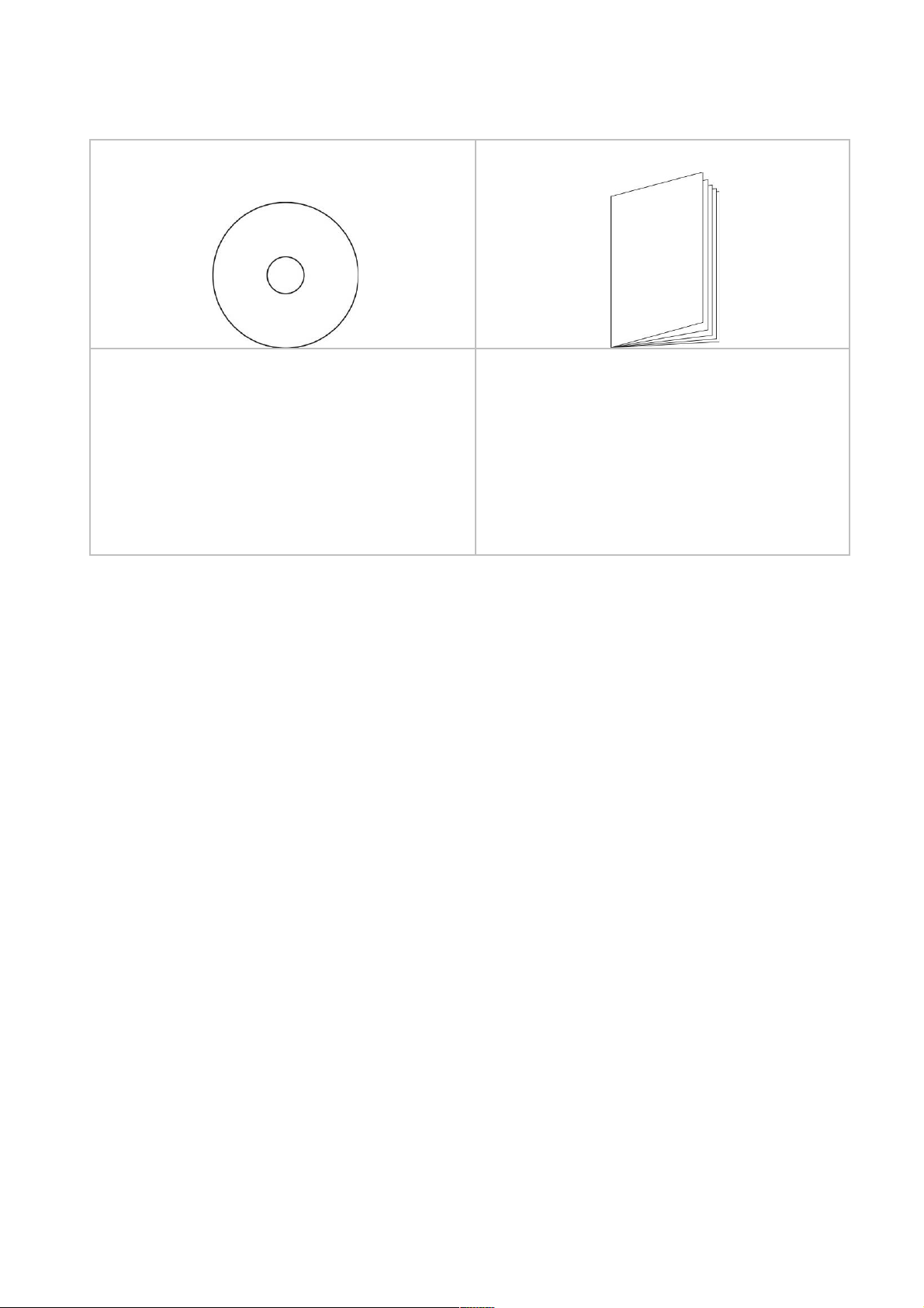
Package Contents
a. Brickcom Software Kit CD b. Easy Installation Guide
Page 5
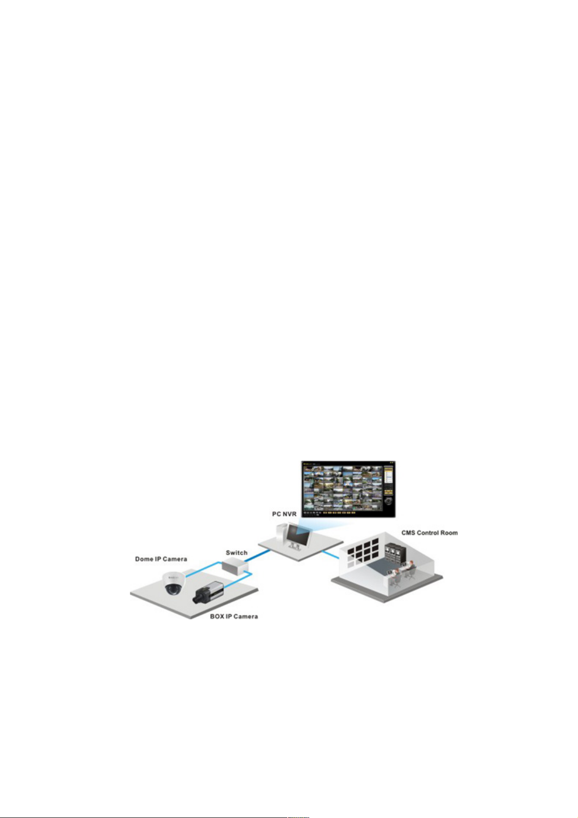
Overview
Brickcom BRC64 is an advanced PC-based NVR that allows users to manage up to 64
Brickcom IP cameras for live viewing and video recording. With the support of Mega-pixel
resolution and H.264 compression, it uses less bandwidth while offering optimal image
viewing and recording quality.
Designed for flexibility and user-friendliness, BRC64 has many features which enable
easy setup and management of the entire IP surveillance system. E-MAP gives users a
full view of the monitored areas and the ‘Smart Camera Search’ feature makes it possible
to gain instant access to any Brickcom IP camera on the specific site. ‘Smart Motion
Detection’ and extensive event configuration work together to make an effective IP
system. Support for viewing and recording at different frame rates is available for efficient
use of disk space. Flexible recording options include manual, event-triggered, scheduled
and continuous.
With Brickcom IP cameras and BRC64, users can quickly build a secure IP surveillance
system.
Page 6

System Requirements
Operating System:
Microsoft Windows XP
Microsoft Windows Vista
Microsoft Windows 7
Computer:
IBM PC/AT compatible.
CPU:
Pentium 3GHz or faster.
Memory:
1024 MB or more.
Monitor:
1024 x 768 pixels or more, 24-bit true color or better.
HDD
2048 MB or more.
Network Interface:
10/100Mbps network interface card must be installed.
Web Browser:
Microsoft Internet Explorer 6.0 SP2 or higher.
6 6
Page 7

Adobe Reader:
Adobe Reader 8.0 or higher.
Audio:
The audio function will not work if a sound card is not installed in the PC. Audio may
be interrupted depending on network traffic.
7 7
Page 8
Software Installation
BRC64 Installation
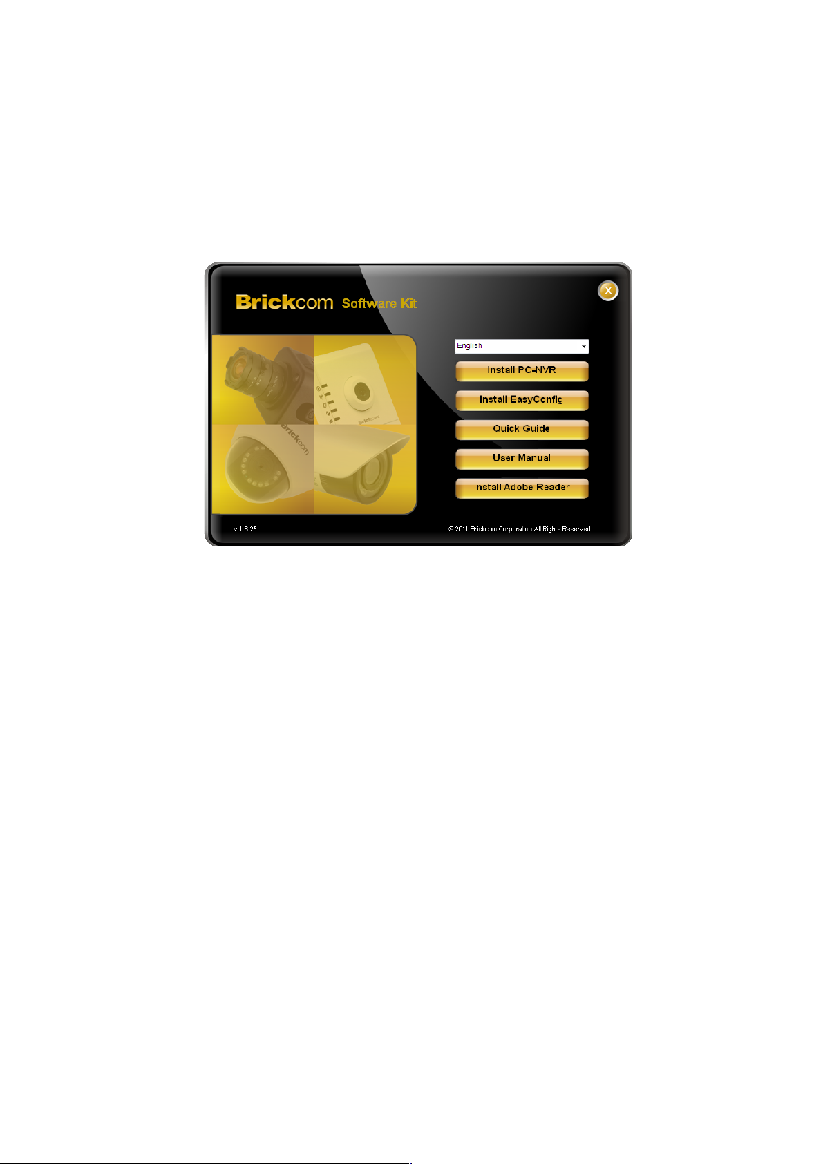
1. Insert the Installation CD into the CD-ROM driver. Run Auto-
Run Tool directly from the CD-ROM to start the installation.
While installing the Brickcom Software Kit for the first time,
select a desired language for the interface. The available
languages are listed in the scroll box. Select
Standard/Professional edition and click <Install PC-NVR> and
follow the steps to install on the desired computer.
8 8
Page 9
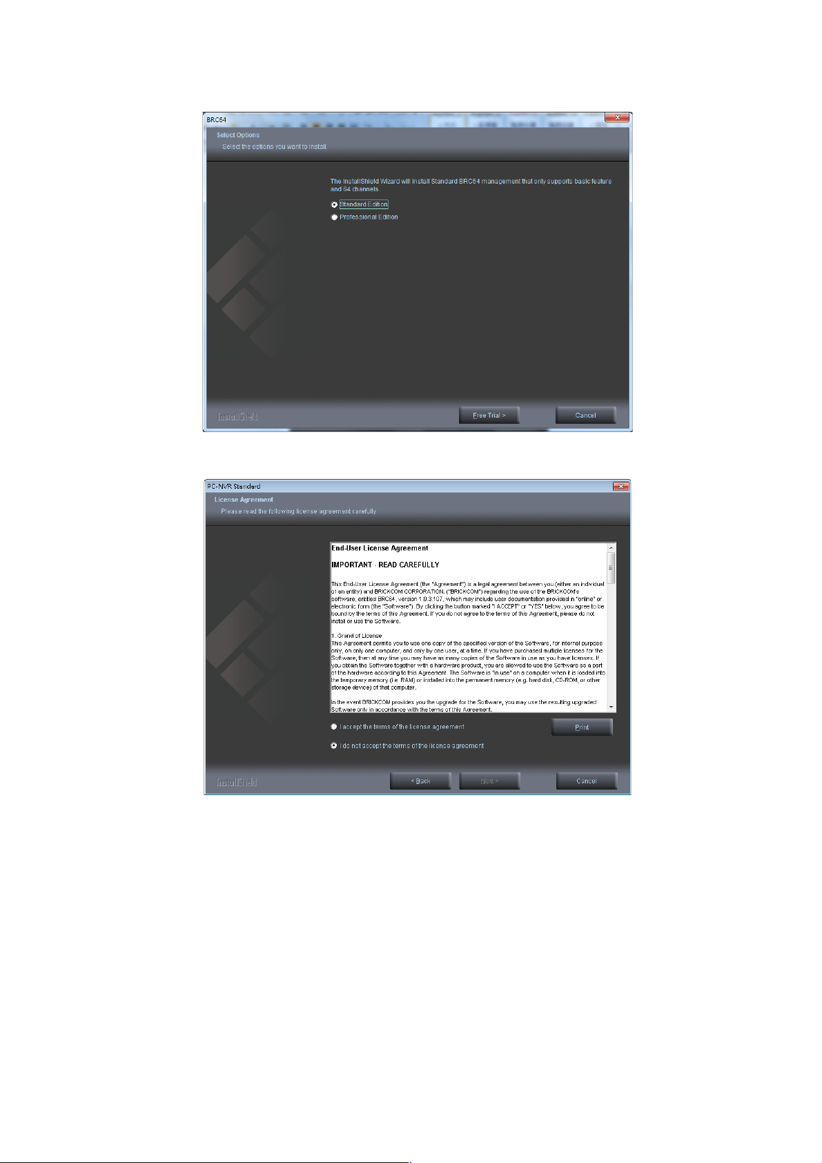
2. In the Install Shield Wizard dialog box, click <Next> to continue.
3. Read the End-User License Agreement and check the option <I
accept the terms of the license agreement>. Click <Next> to continue.
9 9
Page 10
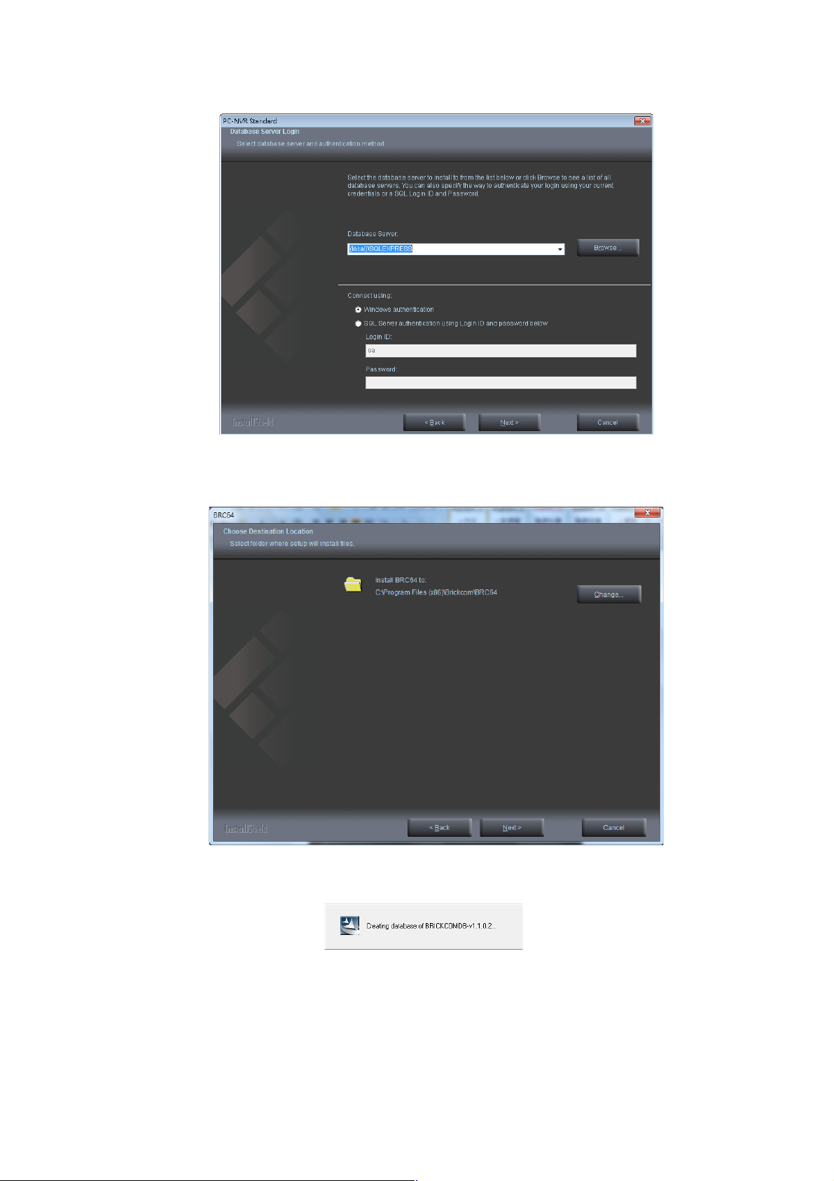
4. Click <Next> to continue installation. If another SQL server already exists
on your device, you can click <Browse> to search.
5. Click <Change> to change the appointed folder where installation
and program files will be stored. Click <Next> to continue.
10 10
Page 11
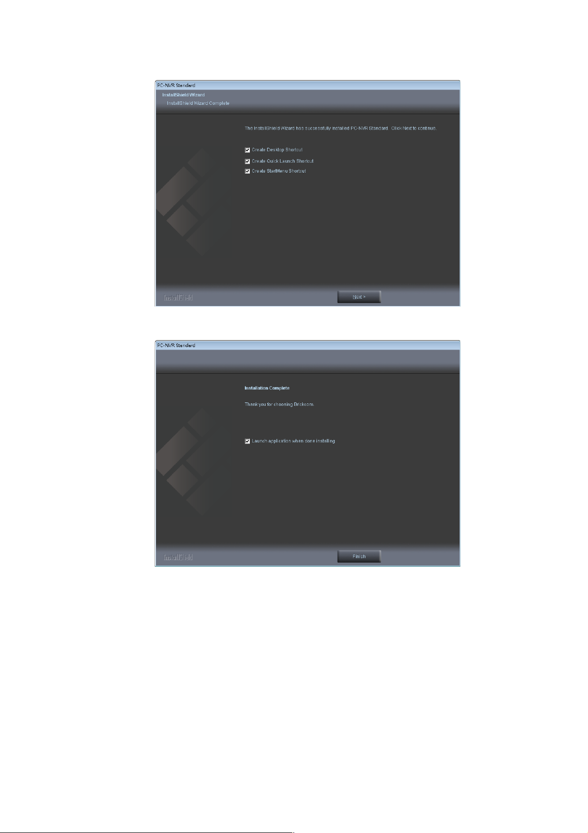
6. Select to create shortcuts. Click <Next> to continue.
7. Click to launch the application, and click <Finish> to complete the
installation and return to Shield Wizard dialog box.
EasyConfig Installation
11 11
Page 12
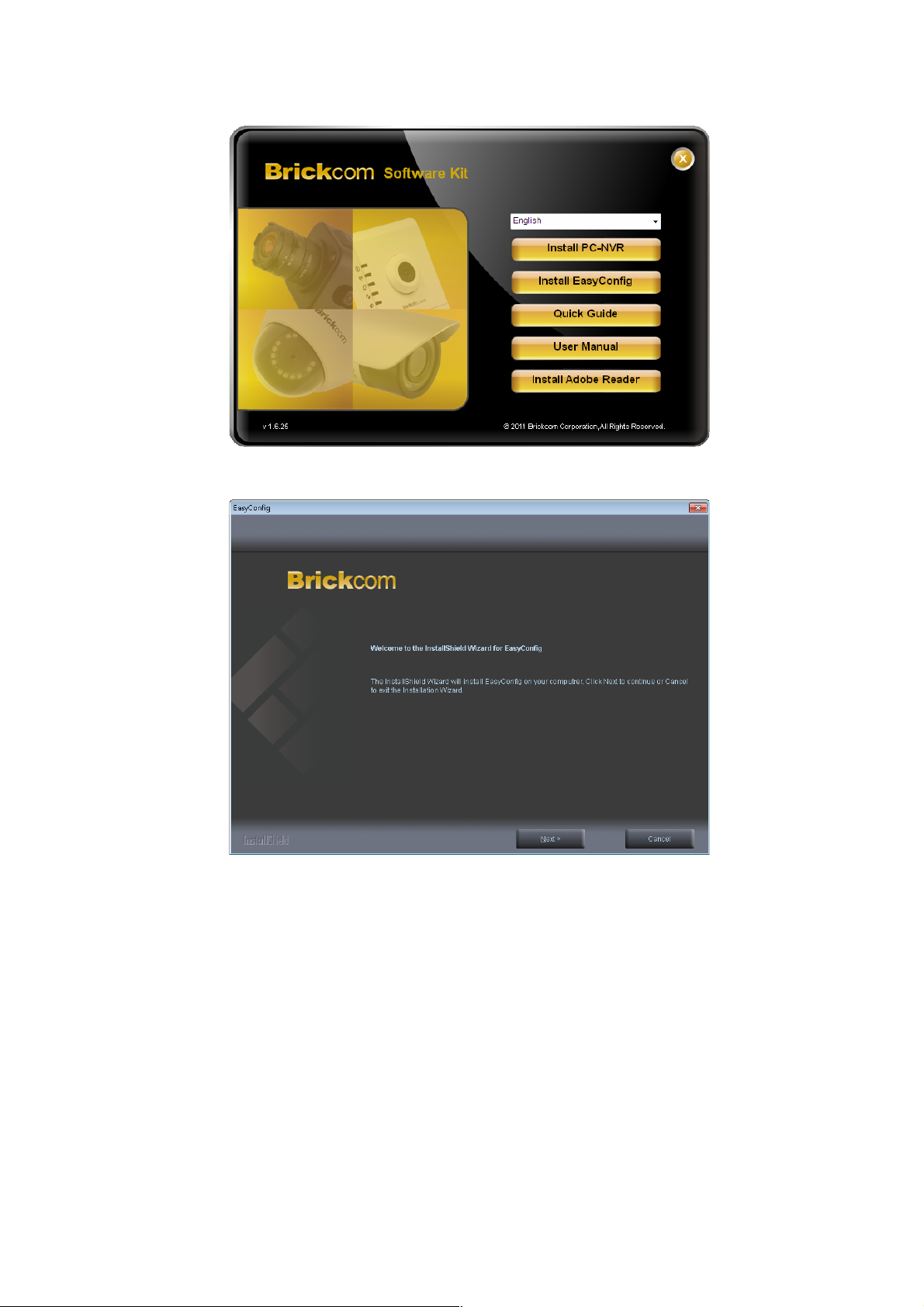
1. Click <Install EasyConfig>.
2. In the Install Shield Wizard dialog box, click <Next> to continue.
12 12
Page 13
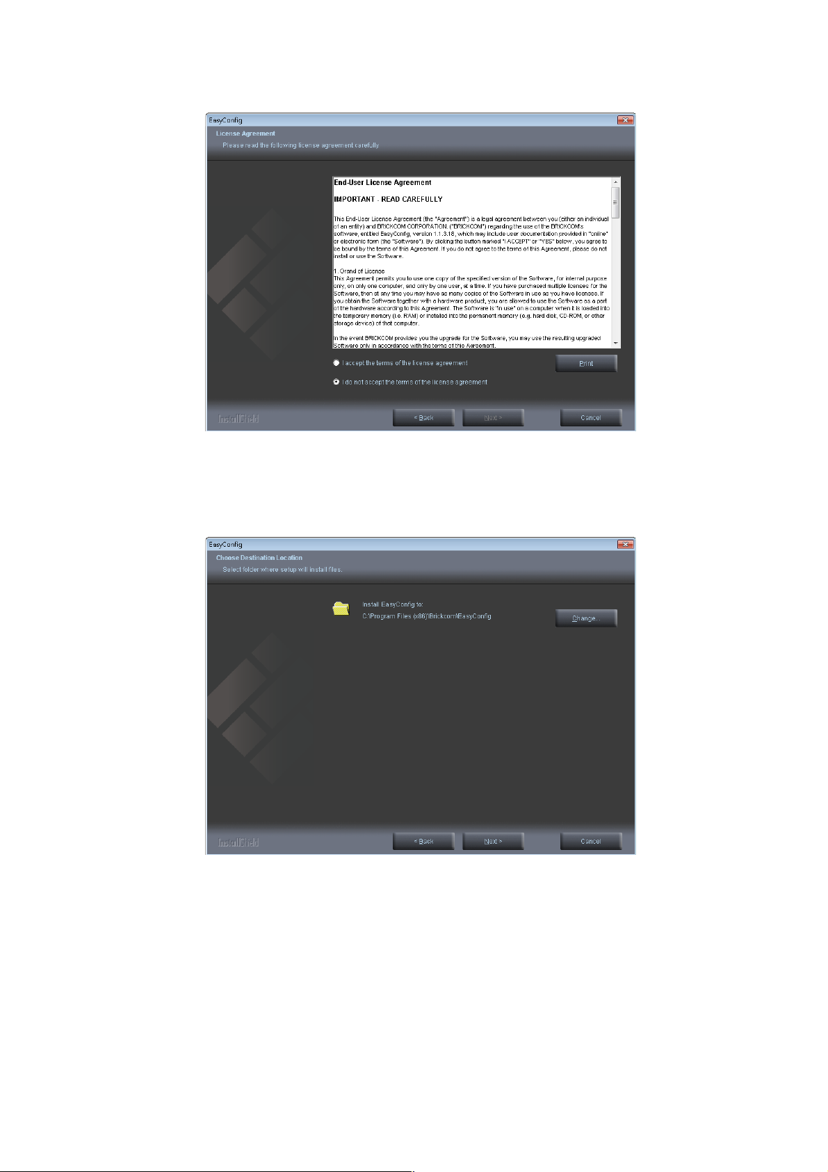
3. Read the End-User License Agreement and check the option <I
accept the terms of the license agreement>. Click <Next> to
continue.
4. Click <Change> to change the appointed folder where installation
and program files will be stored. Click <Next> to continue.
13 13
Page 14
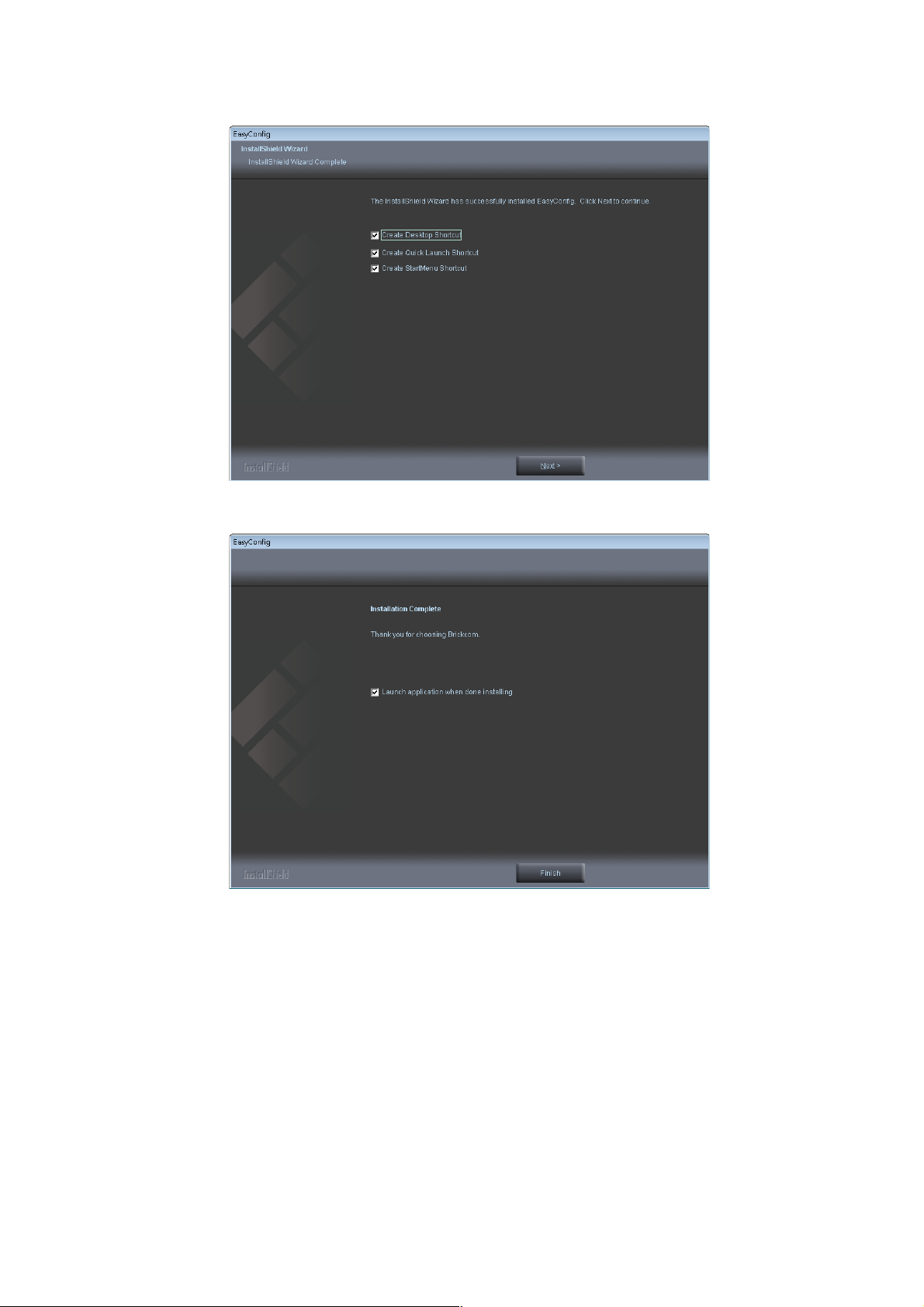
5. Select to create shortcuts. Click <Next> to continue.
6. Click to launch the application, and click <Finish> to complete the
installation and return to Shield Wizard dialog box.
14 14
Page 15
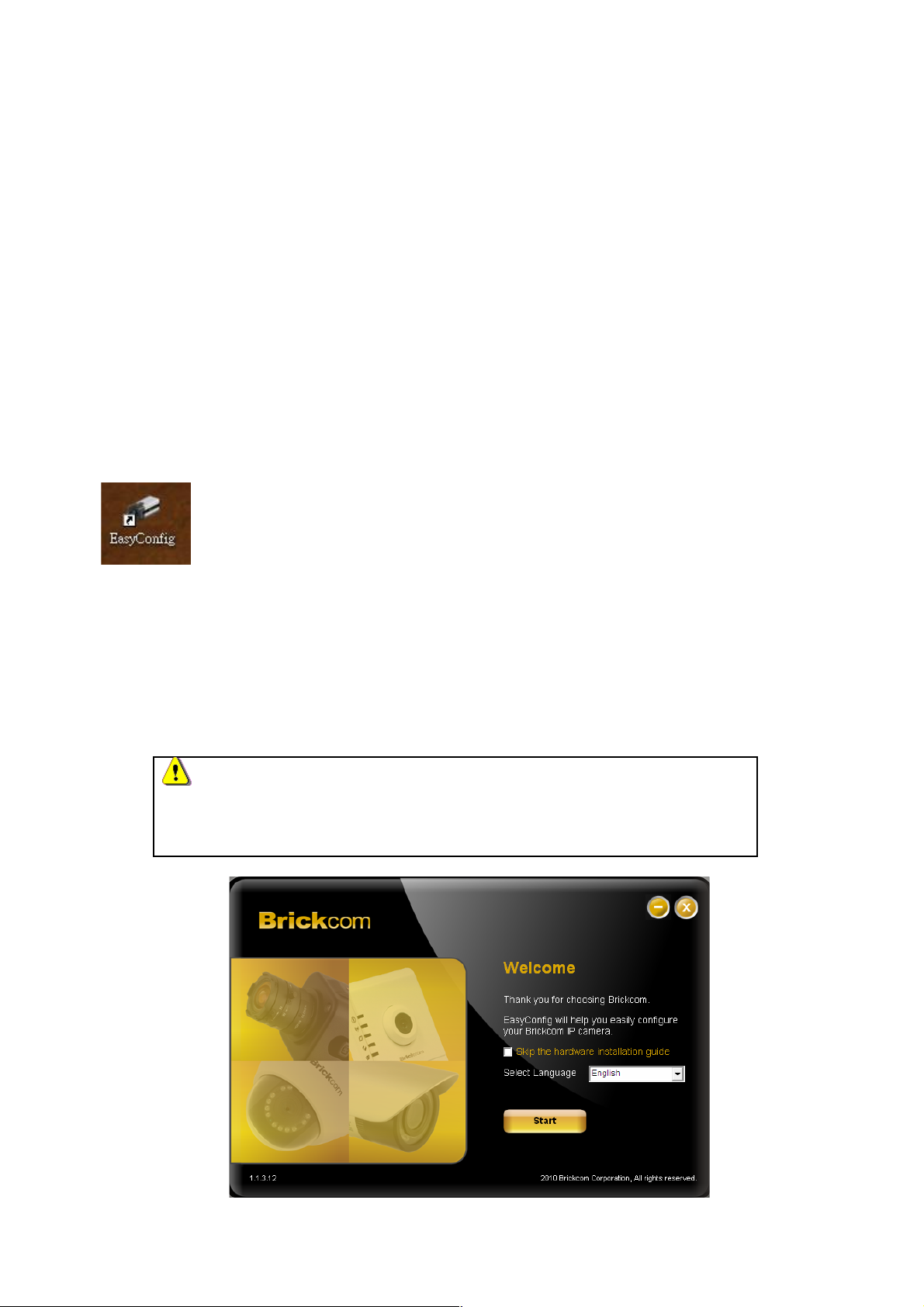
Launch EasyConfig
User can search cameras by EasyConfig and configure the settings below:
IP address configuration.
Easylink configuration.
Live view & Individual Camera Modification.
BRC64.
To launch EasyConfig, select EasyConfig from the start menu. If Complete Setup type
was selected in the software installation, an EasyConfig icon would have appeared on
the desktop. Double click to open the icon.
If Custom Setup type was selected in the software installation and an EasyConfig icon
does not appear on the desktop, the program would have been installed under
‘C:\Program Files\Brickcom\EasyConfig’ unless the program was saved to a preferred
directory.
NOTE - Check <Skip the hardware installation guide> to skip
checking the hardware connection. To check the hardware installation
settings, do not check the box.
15 15
Page 16
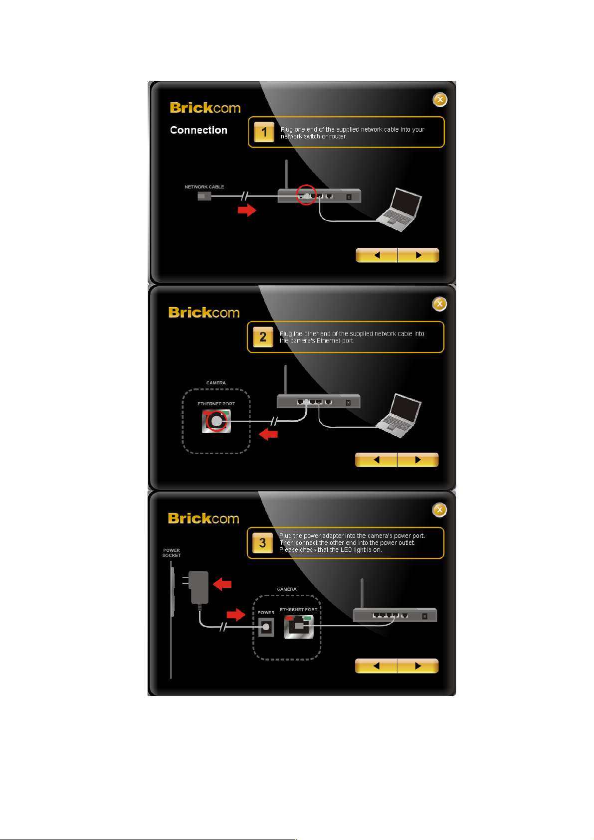
1. Click <Start> to continue. The program will automatically search
for the camera in the intranet.
16 16
Page 17
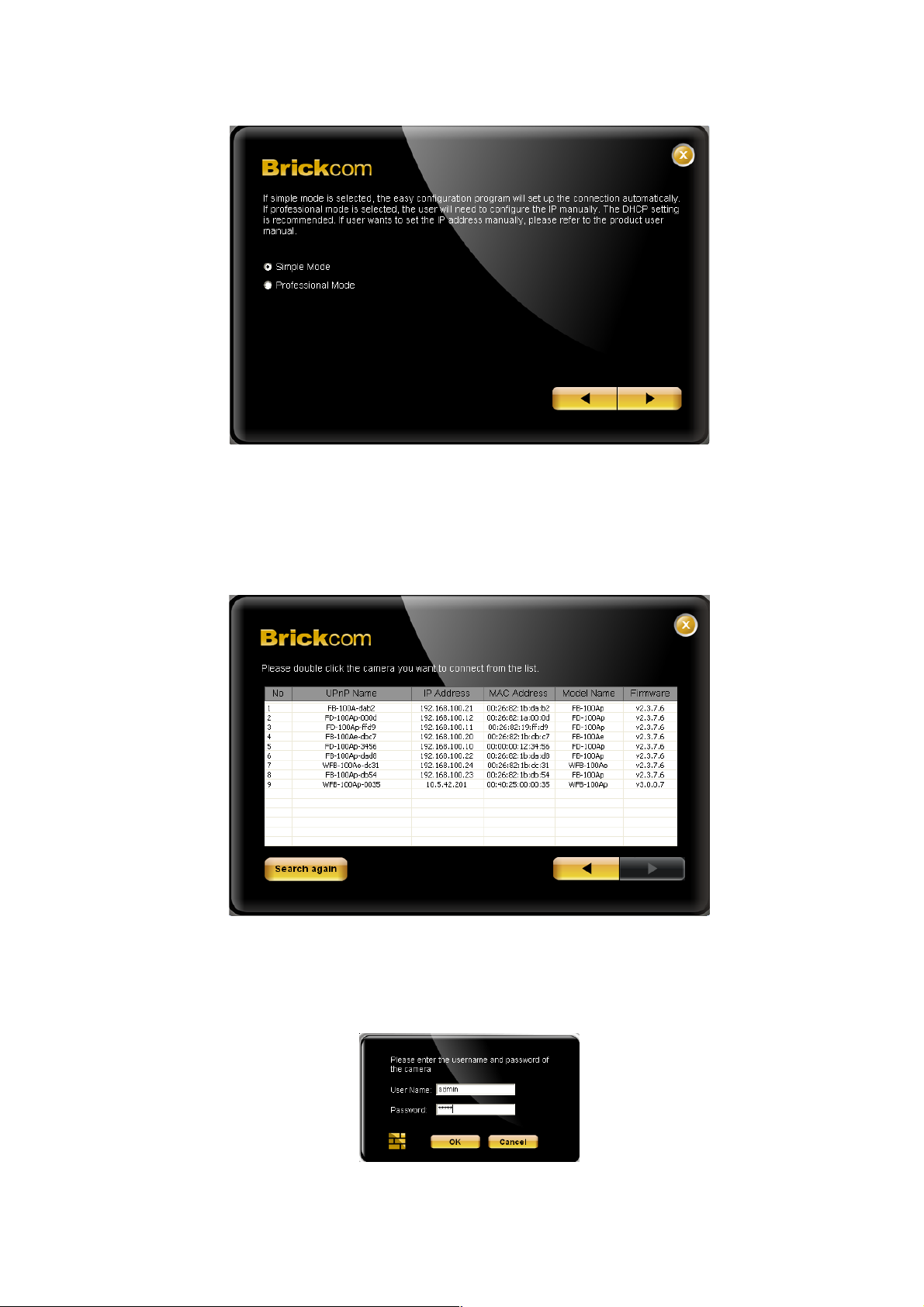
2. Select either <Simple Mode> or <Professional Mode> to obtain the
camera’s IP settings. If <Simple Mode> is selected, EasyConfig
will set up the connection automatically. If <Professional Mode> is
selected, the user will need to configure the IP settings manually.
3. There may be many cameras in the local network. Differentiate the
cameras using their UPnP name. Double click on the camera from
the survey list to connect.
4. Enter the username and password of the camera. For first time
17 17
Page 18
use, the default username and password are ‘admin/admin.’
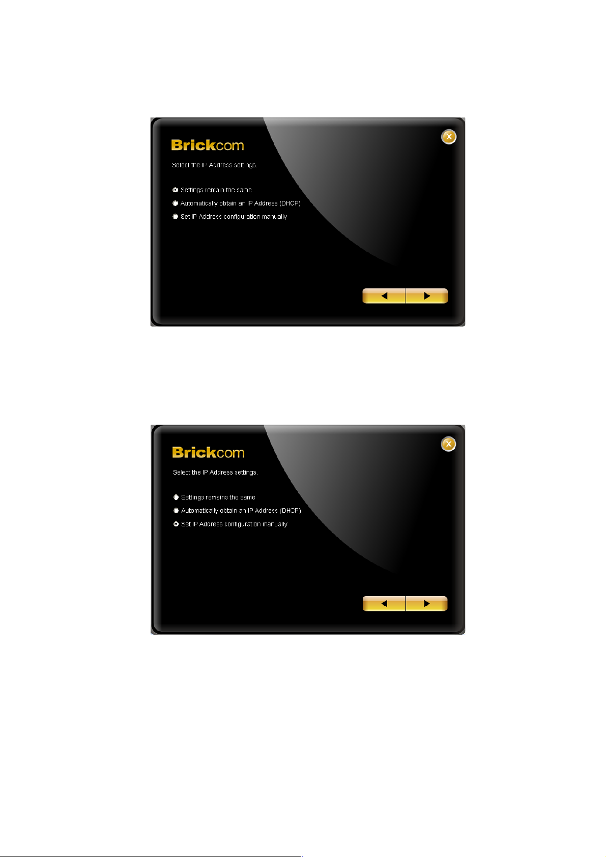
5. For configuring the IP address settings, select either <Settings
remain the same>, <Automatically obtain an IP Address (DHCP)>
or <Set IP Address configuration manually>. The DHCP setting is
recommended.
18 18
Page 19
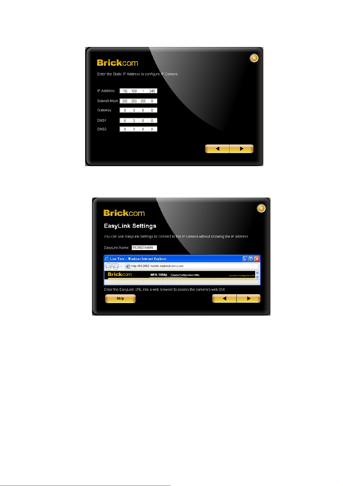
5.1 If <Set IP Address configuration manually> is selected, the above
pages will be displayed.
6. If the camera supports the EasyLink
TM
function, the above page
will be displayed. Otherwise, this page will not be shown. *If
desired, click <Skip> to skip this setting. EasyLinkTM is a unique
Brickcom function which allows users to assign a unique EasyLink
name to their network camera’s IP address. There is no need to
configure the router to open up ports or remember hard-to-
memorize IP addresses. Users can log onto
[uniqueEasyLinkname].mybrickcom.com to view the camera’s web
GUI and live view.
Enter a unique EasyLink name whose length must be
between 5-32 characters.
19 19
Page 20
When finished, click the arrow button to continue.
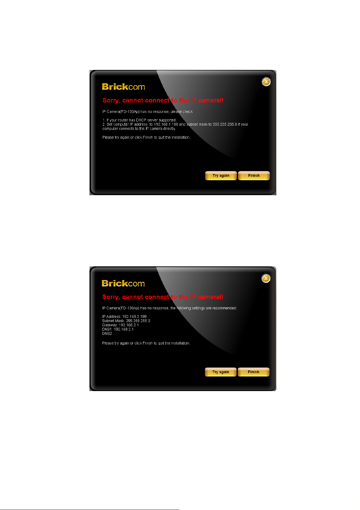
7. When the IP address settings have been configured, the screen
will either display a successful or failed connection message. If the
connection failed, either try again or quit the installation.
7.1 If ‘DHCP IP address settings’ was selected, the failure page will be
displayed as below:
7.2 If <Static IP address settings> was selected, the failure page will
be displayed as above:
7.3 If the connection was successful, the user will see the message:
<Congratulations. The installation of the camera is complete.>
20 20
Page 21
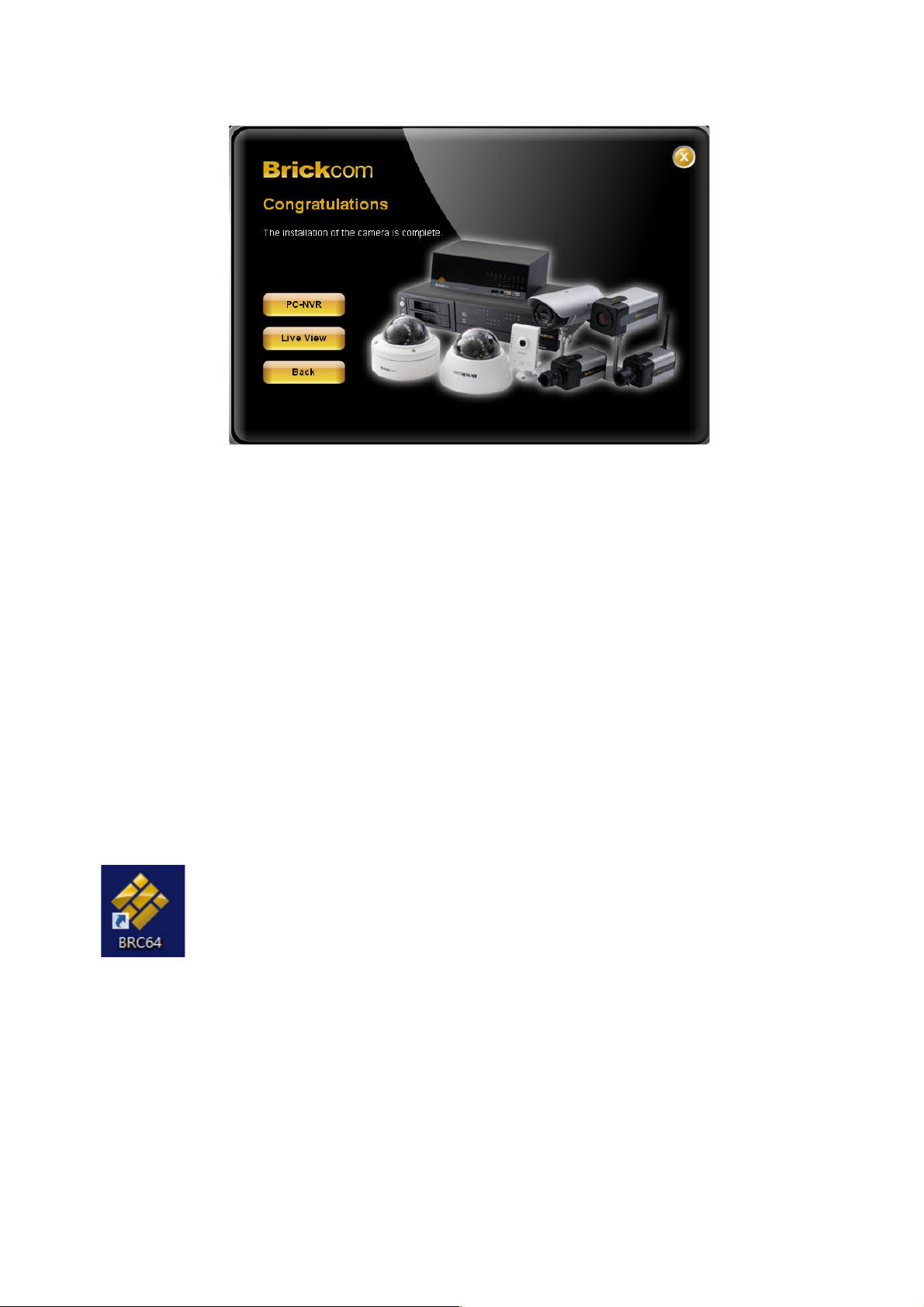
8. When this window is displayed, click <BRC64> to start the BRC64
program, <Live View> to view the live video from the connected IP
camera, or <X> in the top right corner of the screen to close the
installation window. If the user starts the BRC64 program, see
page 18.
Start with BRC64
To launch BRC64, select BRC64 from the start menu. If <Complete Setup> type was
used in software installation, a BRC64 icon would have appeared on the desktop.
Double click to open the icon.
If <Custom Setup> type was selected in the software installation and a BRC64 icon does
not installed on the desktop, the program would have been installed under ‘C:\Program
Files\Brickcom\BRC64\EXE’ unless the program was saved to a another preferred
directory.
21 21
Page 22
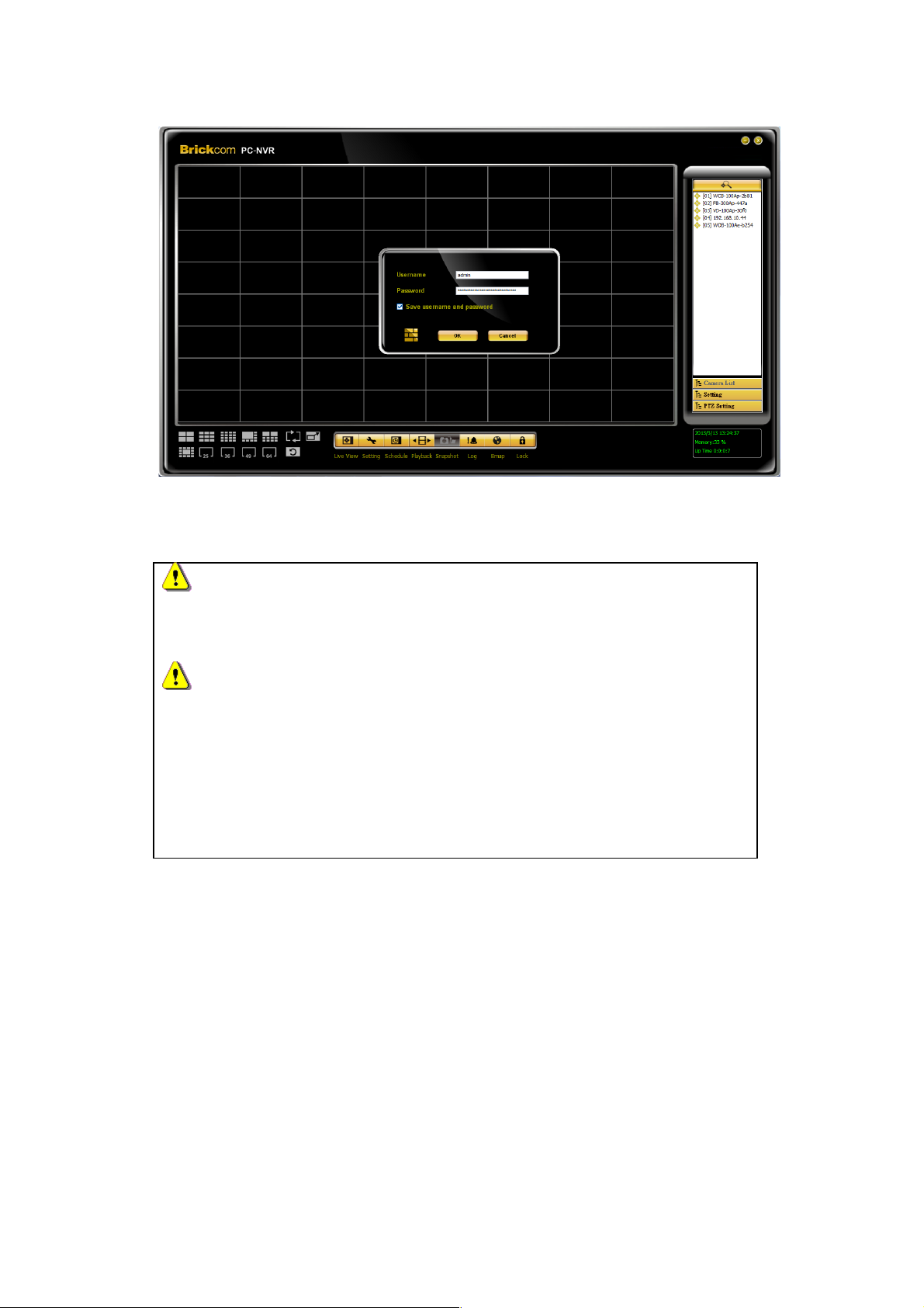
1. For first time use, the user name and password are assigned as ‘
admin/admin’. Click <OK> to login.
NOTE1
Check <Save user name and password> to automatically login when
the BRC64 starts.
NOTE2
Windows only allow administrator account to edit the system folders.
As the result, BRC64 fails to start the service if certain condition is
satisfied:
1. User is unable to edit the system folder.
2. BRC64 is installed in default path.
For the purpose to implement BRC64 normally, please request administrator to carry out
the following steps:
WINXP
22 22
Page 23
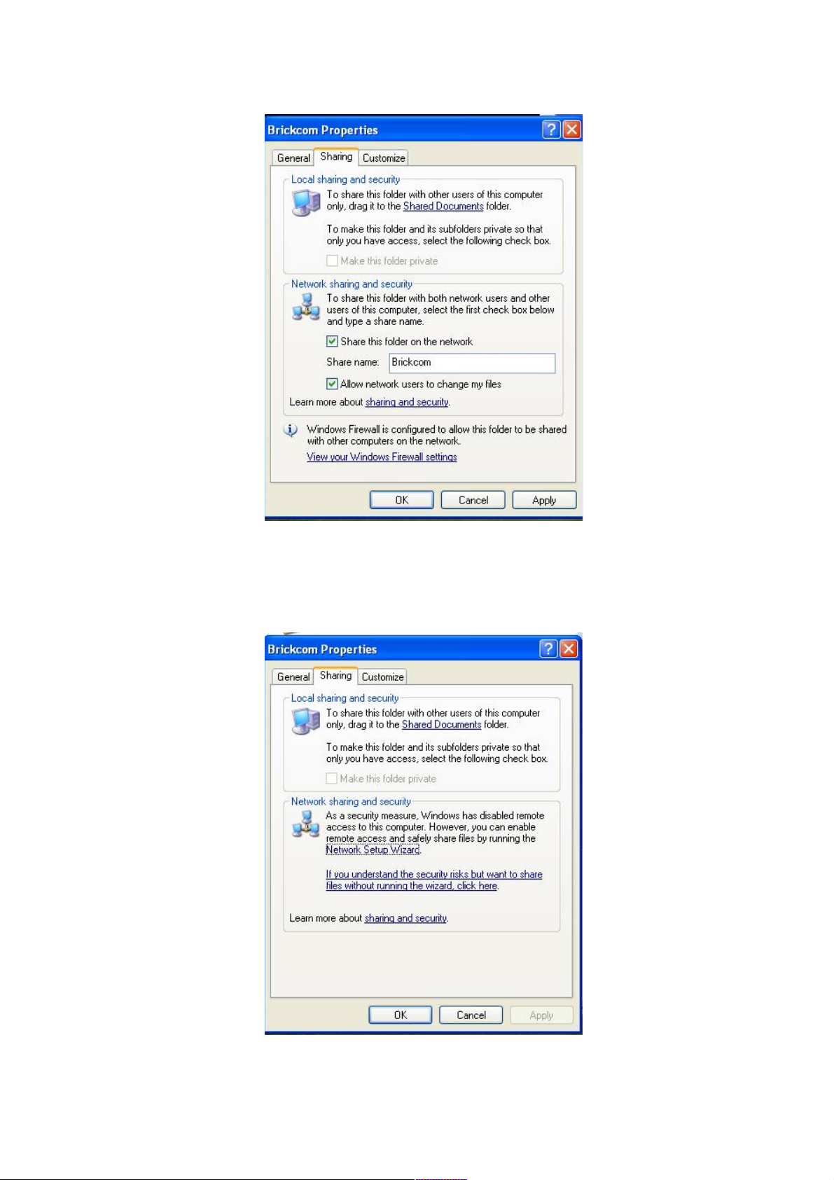
1. Start Windows Explorer to the path via‘Computer->Local
Disk(C:)->Program Files\Brickcom’.
2. Press right mouse click via the path ‘Properties->Sharing’ to
select <Share the folder on the network> & <Allow
network users to change my files>.
3. If operation system is disable to remote access service, the
description in the Properties will show as the description‘As a
security measure, Windows has disabled remote... ’
23 23
Page 24
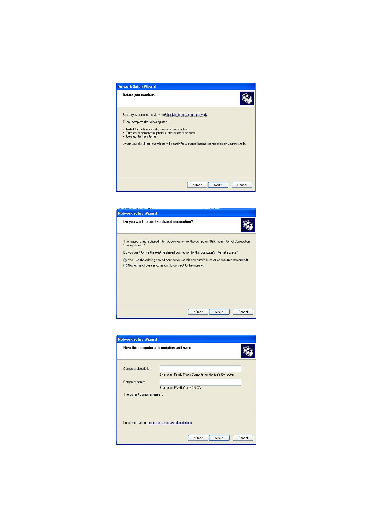
Please refer to below steps for triggering the service.
4. Press <Network Setup Wizard> to enable remote access
service.
5. Press <Next> to continue the wizard.
6. Select the connection to apply the service.
7. Give this computer a description and name.
24 24
Page 25
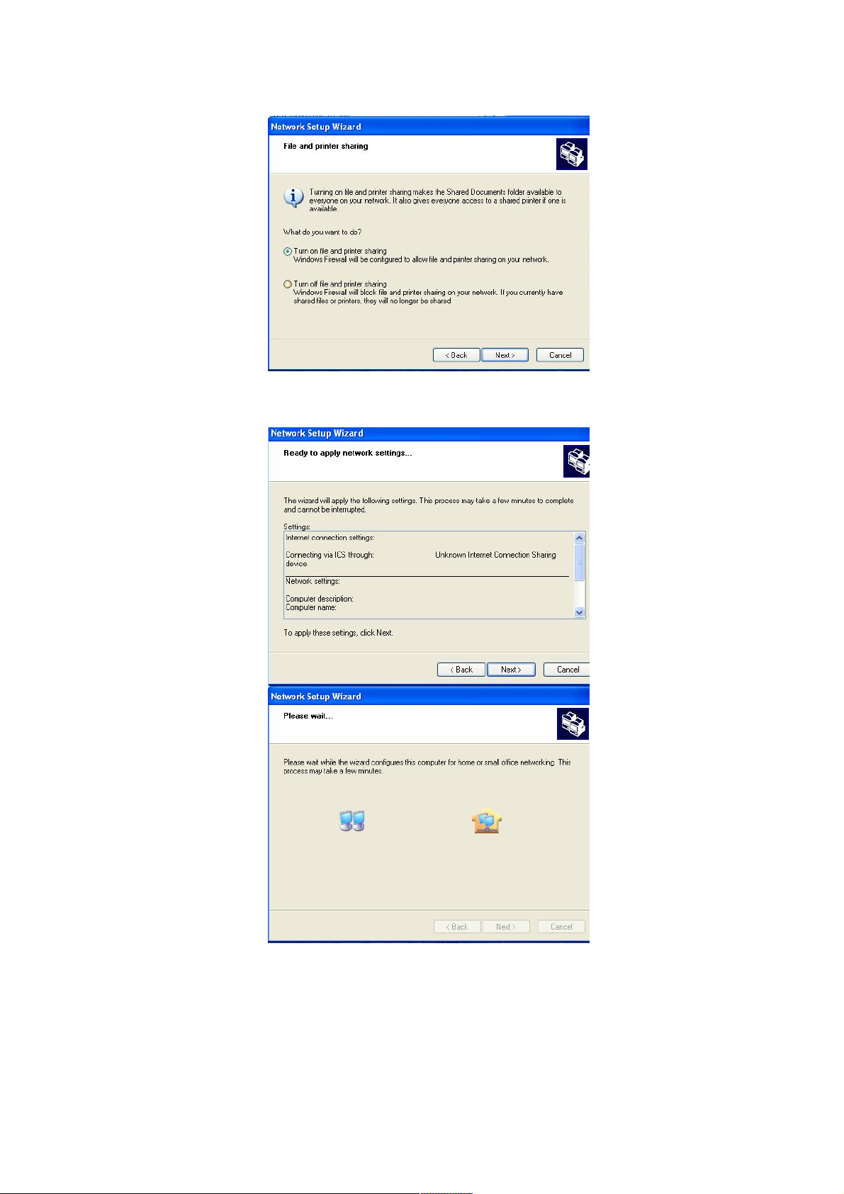
8. Select <Turn on file and printer sharing>. Then press
<Next>.
9. Press <Next> to continue the wizard.
25 25
Page 26
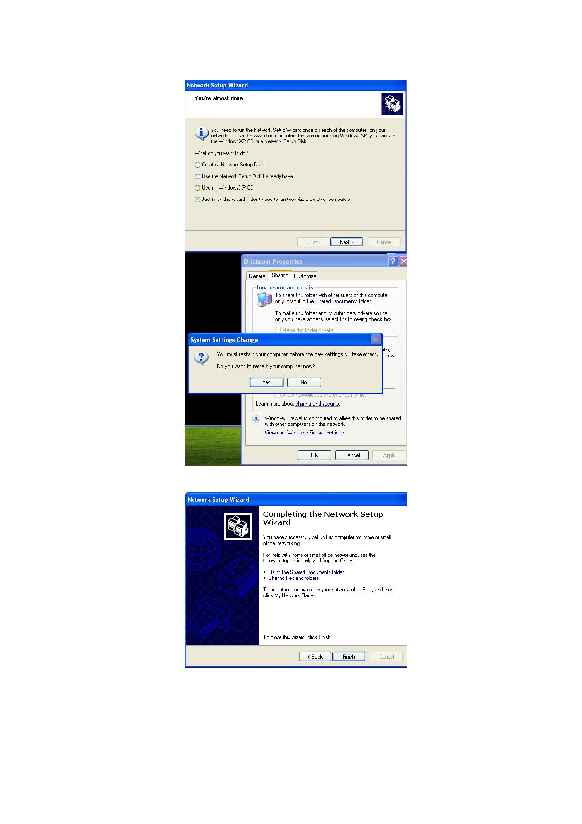
10. Select the description ‘Just finish the wizard…’.
11. Press <Finish> to complete the wizard.
12. Repeat step 1.
WIN7
26 26
Page 27
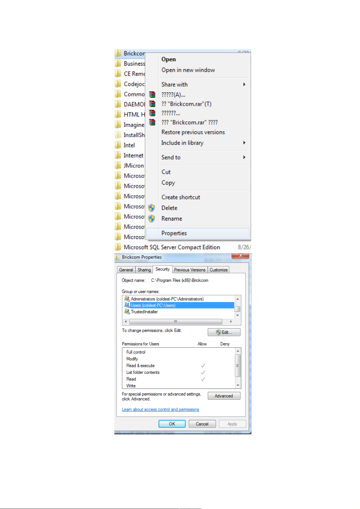
1. Start Windows Explorer to the path via ‘Computer->Local
Disk(C:)->Program Files\Brickcom’. If your computer is
64bit, the default path will be‘Computer->Local Disk(C:)-
>Program Files (x86)\Brickcom’.
27 27
Page 28
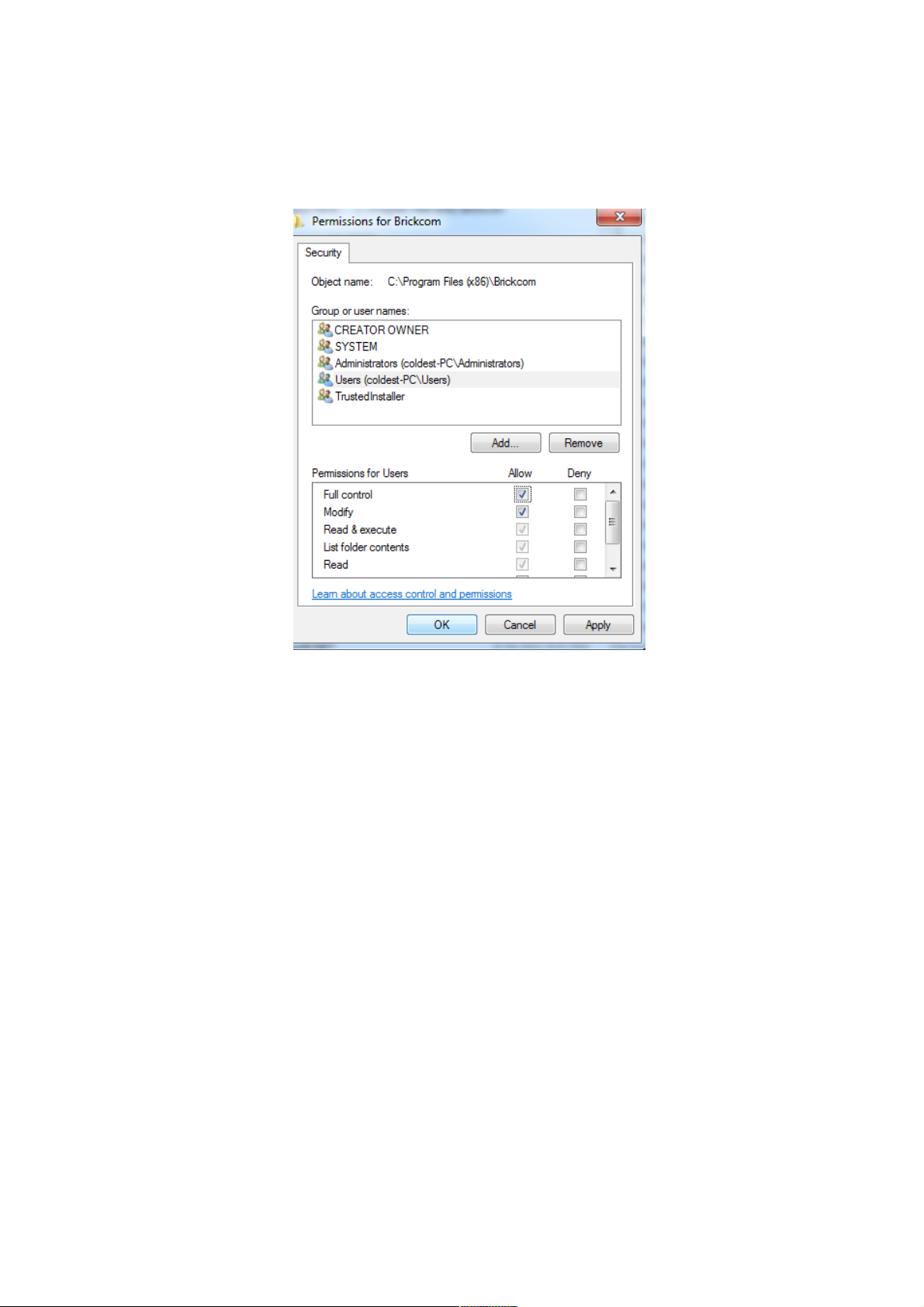
2. Press right mouse click via the path ‘Properties->Sharing’ to
select <Share the folder on the network> & <Allow
network users to change my files>.
3. Assign Users the full ability to control the folder.
Supported Sites
BRC64 for sale has its own individual product key. The supported max sites are 4 as
default. Please input the corresponding product key to increase the max sites(up to 64).
28 28
Page 29
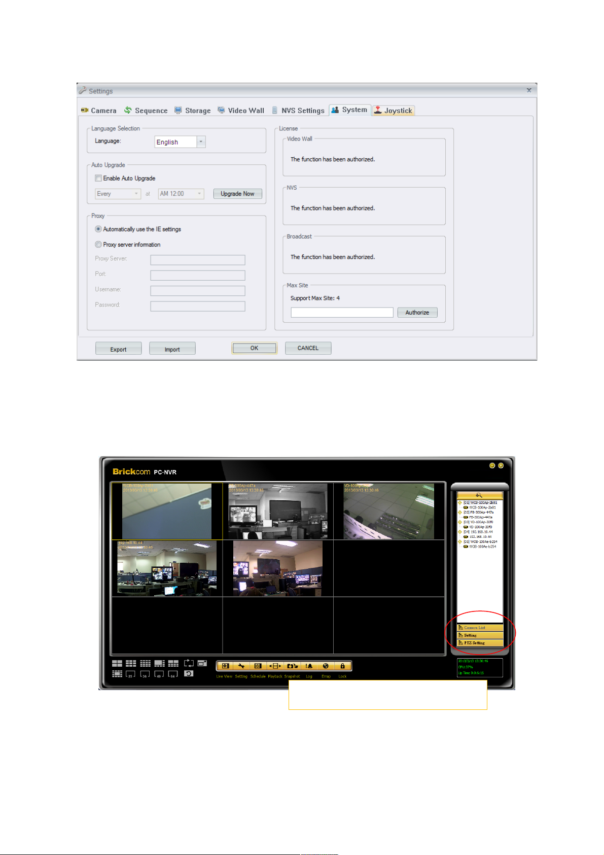
Main Window
29 29
Feature menu:Camera List、Setting、 PTZ
Setting
Page 30
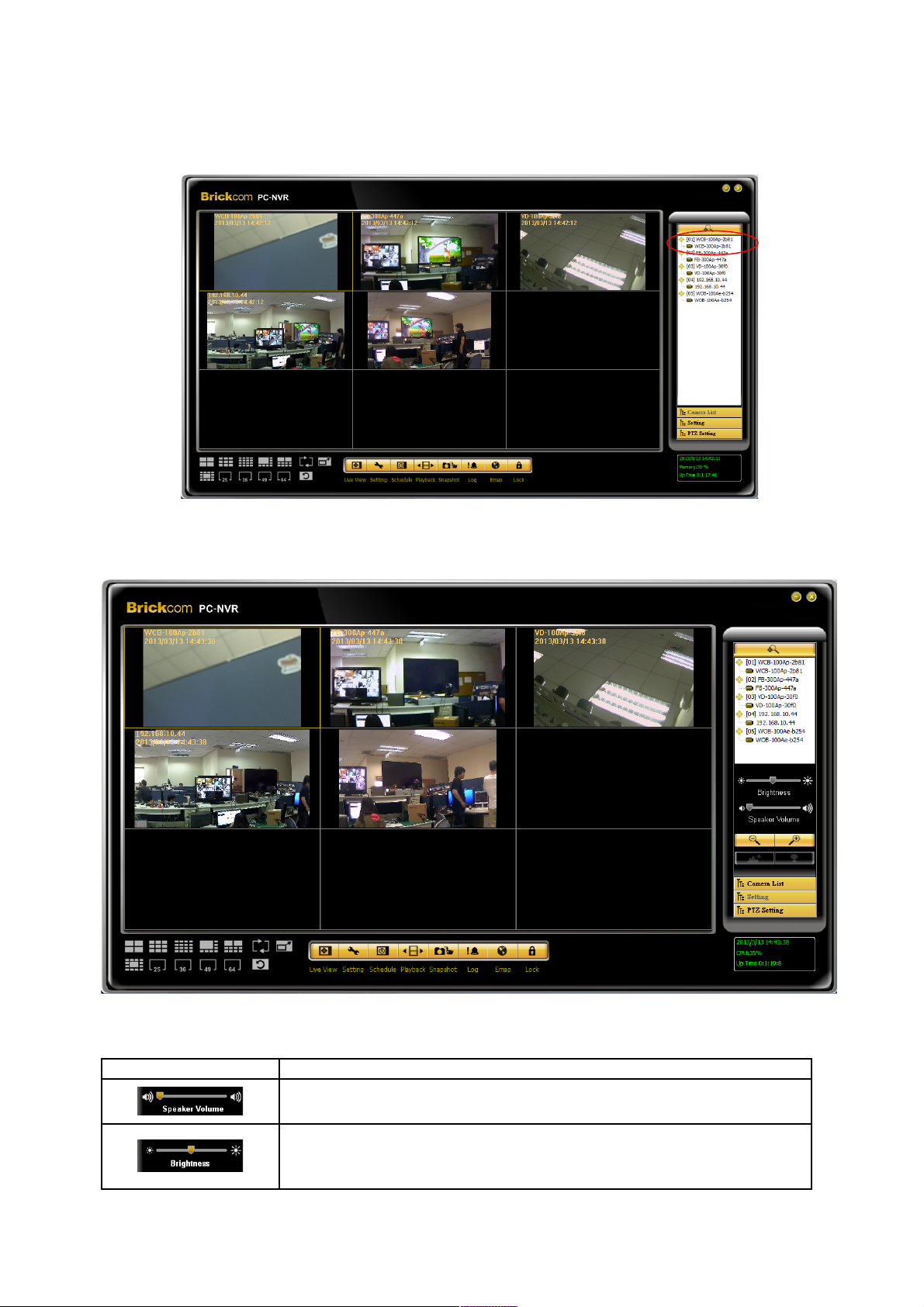
Main Window – Camera List
Main Window – Setting
The usage and function of each button will be briefly described below:
Button Function description
Modify Volume by drag-and-pull the mouse
Modify brightness drag-and-pull the mouse. Double-click the
left mouse bottom to reset to default.
30 30
Page 31
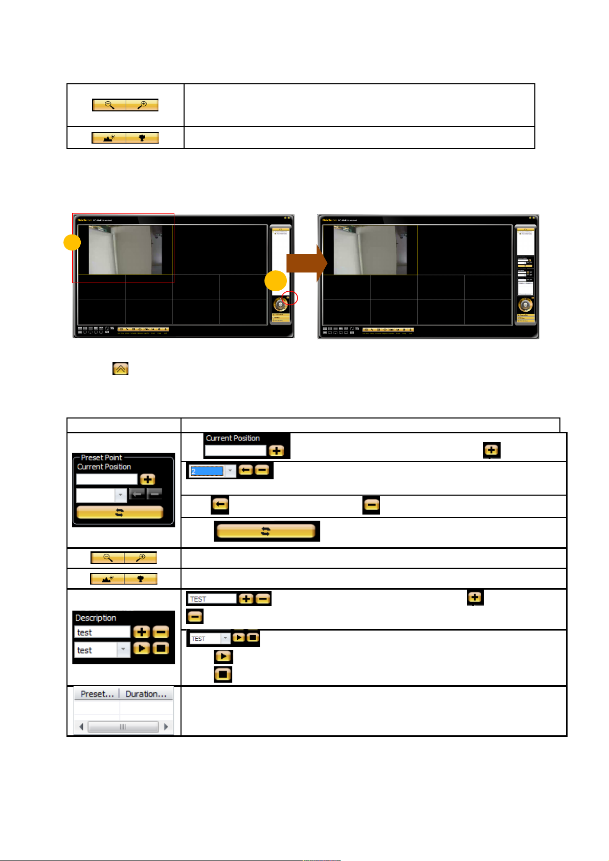
Zoom out / Zoom in - Click to manually adjust the zoom on the
desired grid.
Focus – Click to manually adjust the focus on the desired grid.
Main Window – PTZ Setting
(1) Select camera
(2)Click and popup preset panel and patrol panel.
Button Function Description
Input preset name on edit panel, click to add it.
Select preset point you want to move by selecting drop
down menu.
Click to go to preset point. Click to delete perset point.
Click to synchronize setting with camera.
Zoom out /in - Click to manually adjust the zoom on the desired grid.
Focus – Click to manually adjust the focus on the desired grid.
Insert preset name on edit panel, Click to add, Click
to delete.
Drop down menu to add preset points into patrol set.
Click to play current patrol set.
Click to stop patrol.
Displays added preset points.
31 31
1
2
Page 32
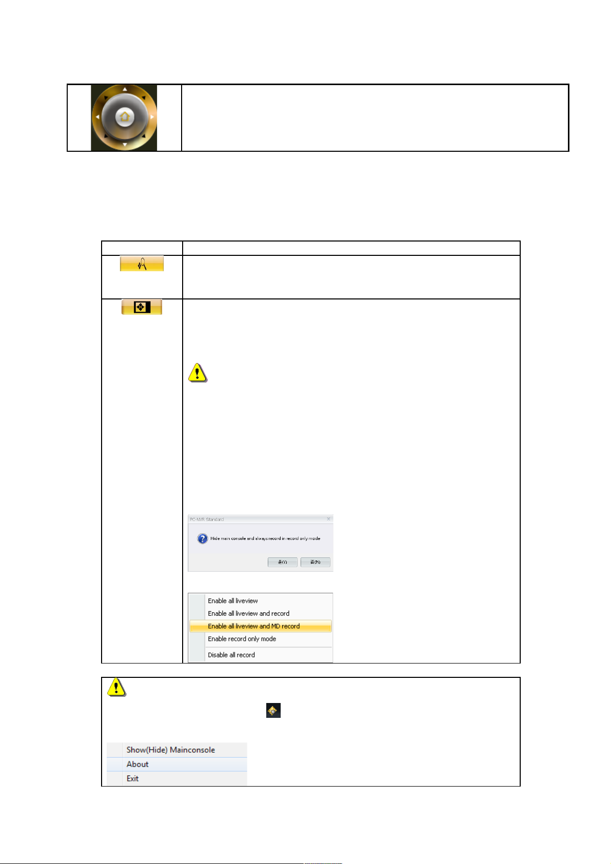
PTZ Panel- Click on the arrows to pan and/or tilt the desired camera
Main Window – other buttons
Button Function Description
Click this button to search for Network Camera devices
within the LAN. The button is moving round and round.
Live View - Click on the <Live View> icon to view live video
feed. After viewing recorded video, click this button to
return to the live mode.
NOTE: The menu will jump if you use your mouse to
click on this icon. The content of this menu is:
Enable all live view.
Enable all live view and record.
Enable all live view and MD record.
Enable record only mode and hide BRC64 main
console.
Disable all record.
NOTE 1
Please use right mouse click in the right bottom side of Windows
desktop to show/hide BRC64 main console.
32 32
Page 33
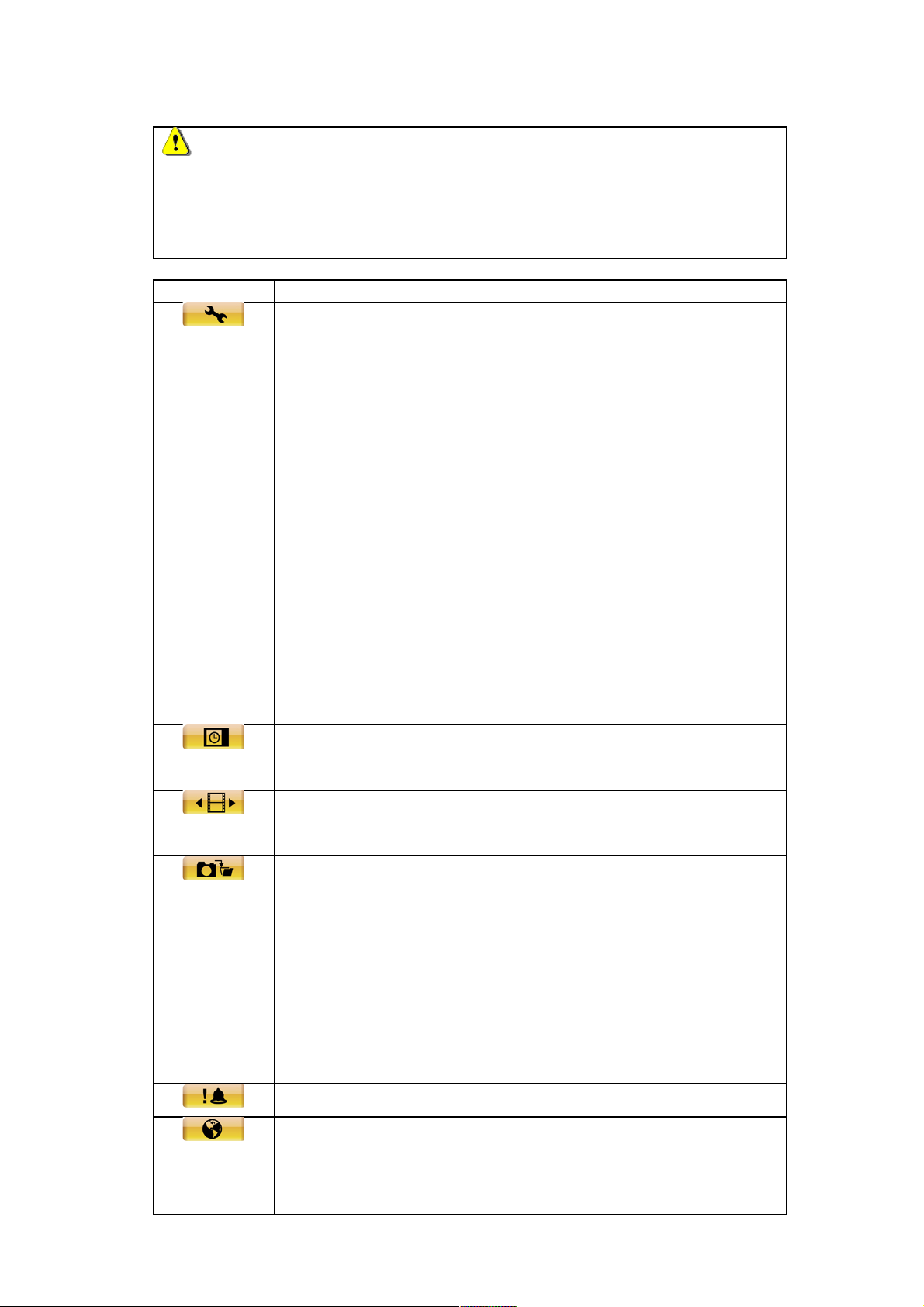
NOTE 2
<Reord only mode> will close all live view functions to accelerate the
system effect. Press <Re-sort Camera> or <Enable all live view> to
recover the related services.
Button Function Description
Setting - Click on the <Setting> icon to adjust the following
configuration:
System information
Monitor CPU&Memory Usage, Disk Usage and Network
Usage.
Settings
Modify the setting of camera, Sequence, Storage, Video
Wall, NVS, and System.
Account Management
Enable / Disable the authority for accounts to configure the
cameras and functions.
Alarm & Event Setting Dialog
Modify the immediate actions while events are happening.
Schedule record - Click on the <Schedule Record> icon to
schedule recording times for cameras on the network.
Playback - Click on the <Playback> icon to view recorded
video stored in the HDD of the connected IP camera.
Snapshot - Click on the <Snapshot> icon to save snapshots
including:
Snapshot Single-Snapshot single image.
Snapshot Matrix - Snapshot all window grids
image.
Snapshot All - Snapshot all video images
individually.
Event - List of system and camera event logs.
E-map - Click on the <E-map> icon to open the E-map
program. The E-map is a program that allows the user to
illustrate the positions of the cameras on a self selected
33 33
Page 34
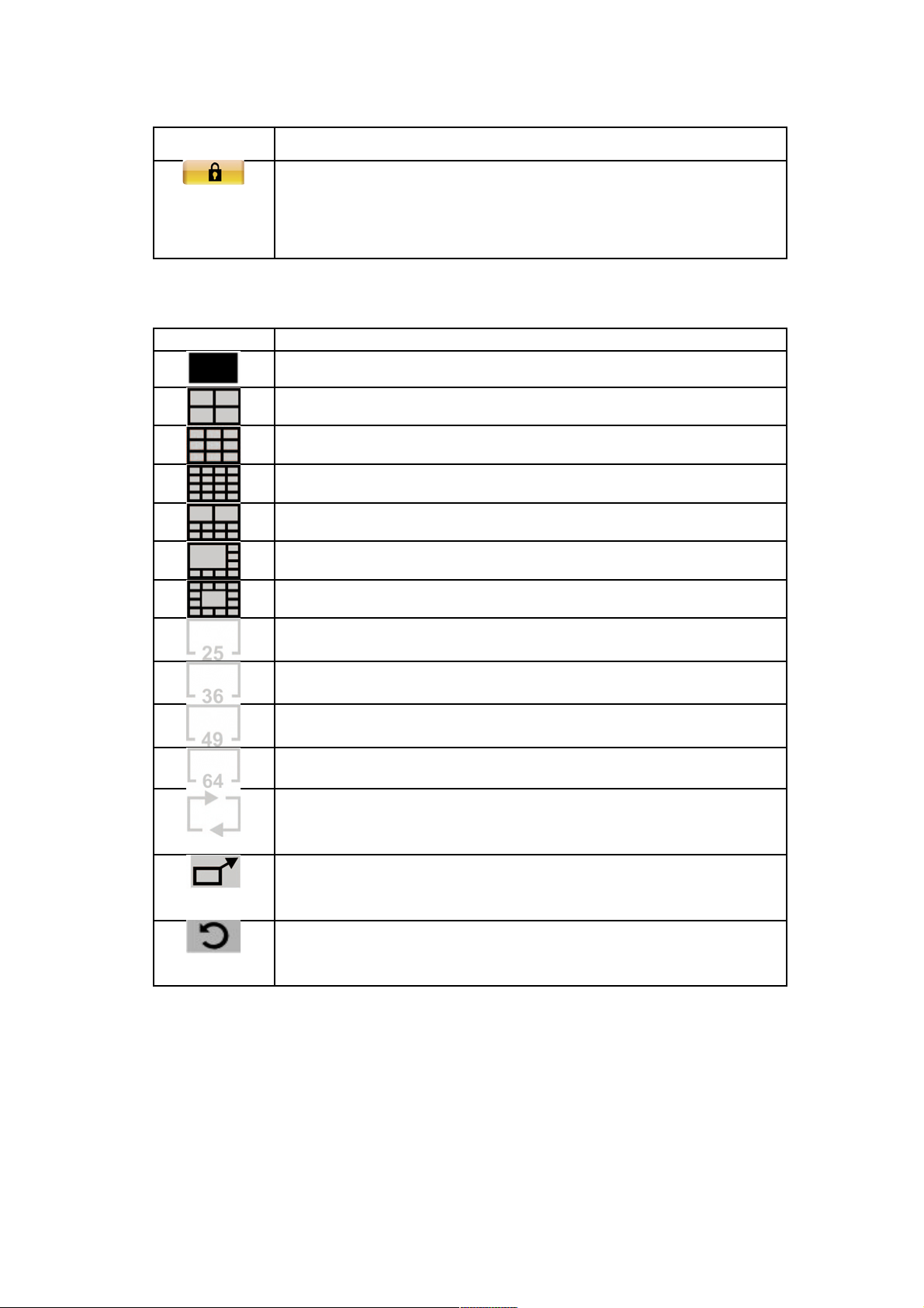
image.
Lock - Click on the <Lock> icon to lock the BRC64 without
closing the program. To re-access the BRC64, the user will
be prompted to enter the username and password.
Display Modes
Button Function Description
1-window mode
4-window mode
9-window mode
16-window mode
10-window mode
8-window mode
13-window mode
25-window mode
36-window mode
49-window mode
64-window mode
Sequence: This function is used to set the display
sequence.
Full Screen: Enlarge the viewing window to fit full screen.
Hit <Esc> to exit.
Resort Camera: Resort Display Window Grids; to rearrange
camera images of connected sites in order.
Configure the BRC64
Live View
34 34
Page 35

With the live view function, the user can view live video feed from any IP camera
connected to the network. To operate this feature:
1. Click on the <Live View> button to see the live view.
Right click on a desired grid and select < Disable Live View >
from the pull down menu to disable live view.
2. Click <UPnP Search> button on the control panel to
start searching for UPnP devices within the LAN.
3. Use the Display Modes to determine the amount of sites to
view.
4. The BRC64 allows the user to assign any camera in the site
tree to any grid in the main window.
Step 1: Selects the camera to be viewed from the site tree.
Step 2: Drag and drop the selected camera into the window to
view.
Re-sort Camera
If the camera sites are rearranged during live view, return to the original camera order by
right pressing on any grid square and selecting <Re-sort camera>.
35 35
Page 36
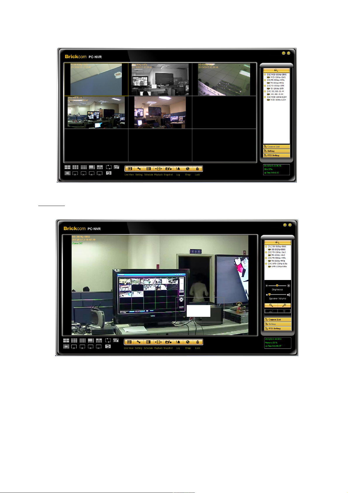
Zoom In – Double click on the desired grid, and use the scroll wheel on the mouse to
zoom in and out of the live view window.
If the camera has pan, tilt, and zoom capabilities, the following control panel will be
displayed.
36 36
Page 37
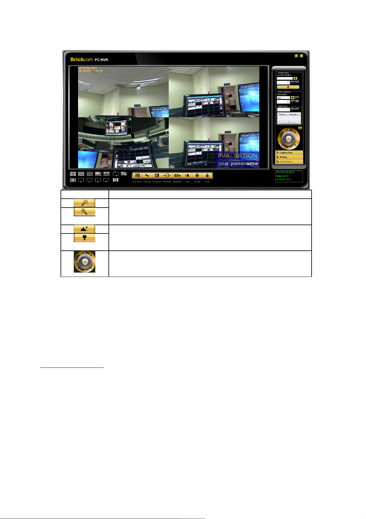
Button Function description
Zoom out / Zoom in - Click to manually adjust the zoom on
the desired grid.
Focus – Click to manually adjust the focus on the desired
grid.
PTZ Panel- Click on the arrows to pan and/or tilt the desired
camera.
Setting
With the Setting tool, the user can manage up to 64 camera sites on the BRC64. Use
this tool to add, remove, or configure cameras.
Add/Remove a Site
There are two ways to add a site.
37 37
Page 38
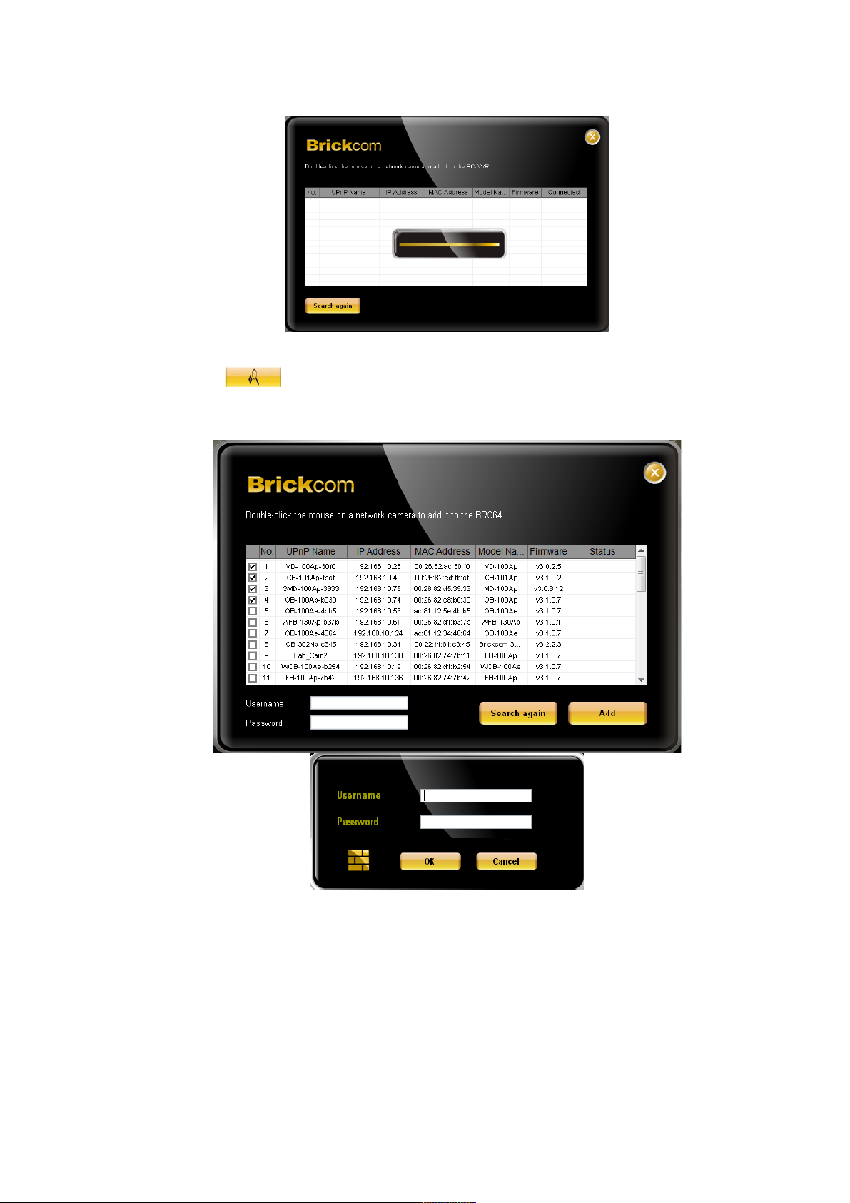
1. Setup the Site via UPnP Device Search.
2. Click <UPnP Search> button on the control panel to start
searching for UPnP devices within the LAN.
Click and select the Network Camera from the survey list. Enter the
user name, password and select the stream type from the drop-down
menu. For first time use of an IP camera, the user name and
password are ‘admin/admin’.
Setup the Site Manually
Camera
38 38
Page 39
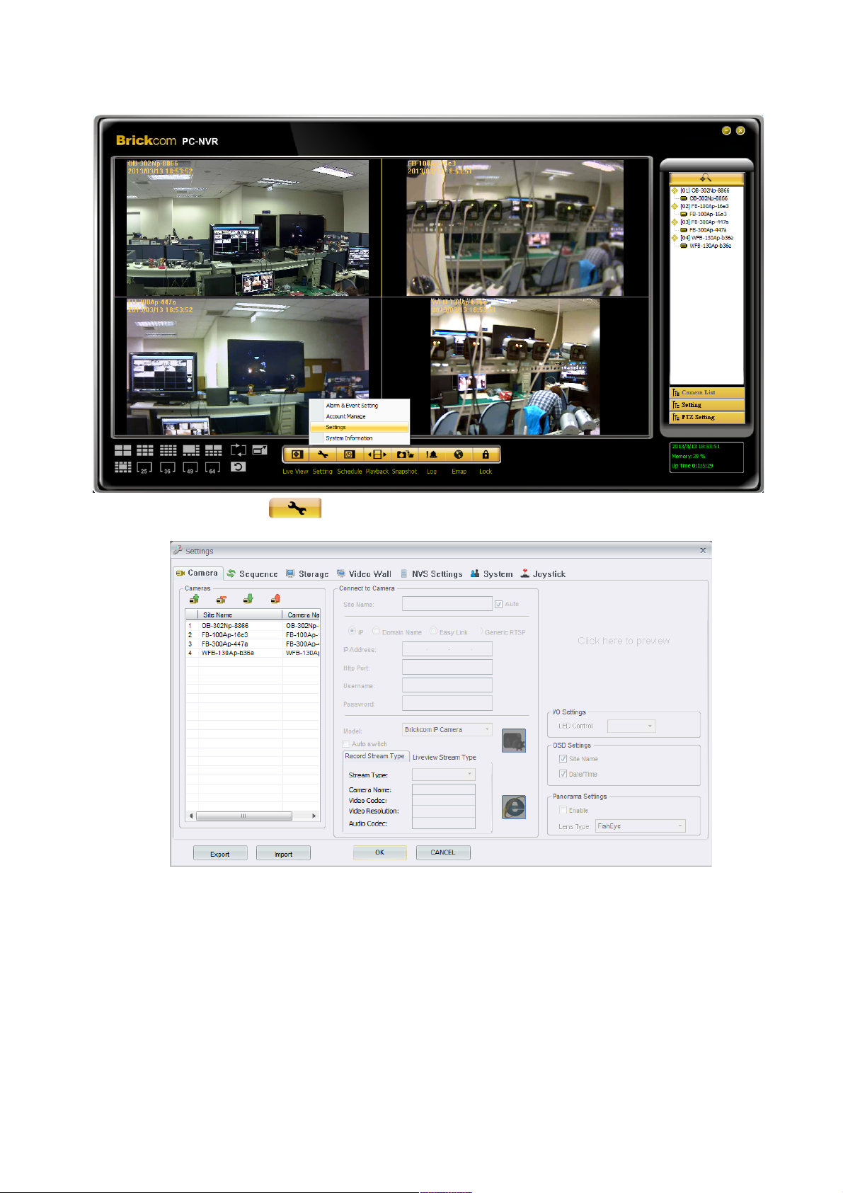
1. Click on the <Settings> icon and select <Settings>.
2. The figure below will be displayed.
39 39
Page 40
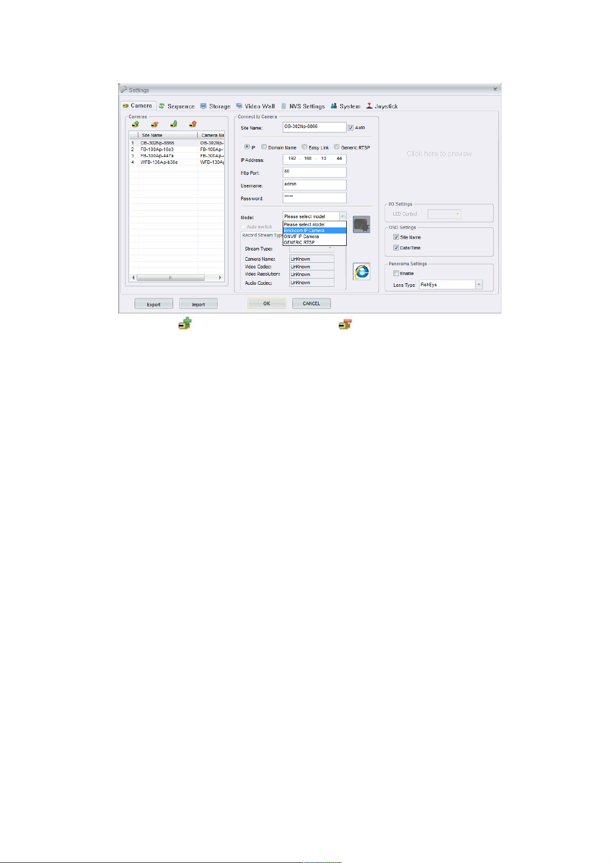
2.1 Click button to add a site. Click to remove it.
How to add a site
2.1.1 Enter the required information, including IP, Http port,
Username, and Password of the Network Camera.
2.1.2 Select the <Model> of the IP Camera from the drop-
down menu to automatically retrieve the Site name from the
UPnP name of the camera being added add to the BRC64.
2.1.3 Click <OK> to complete the setting. Otherwise, rename
the 'Site name' is available with 25 character limit.
2.1.4 Dual Stream supported and you can select different
stream for recording or liveview by selecting Record Stream
Type and Liveview Stream Type. Auto switch will
automatically change liveview stream and record stream in a
different display mode.
2.1.5 For a 360-degree camera, you can enable fisheye de-
warp feature by checking ‘Enable’ box on the Panorama
setting.
40 40
Page 41
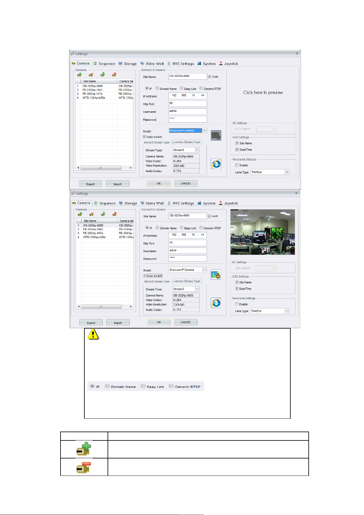
NOTE
If the camera already has a configured domain name or Easy
Link, user can enter Domain Name or EasyLink name or
Generic RTSP instead of IP address by selecting
connection type. If your
camera’s link for EasyLink is ‘123.mybrickcom.com,’ please
enter ‘123’ in the row space of EasyLink name.
Button Function Description
Add a site.
Delete a site.
41 41
Page 42
Click to modify the Brightness, Contrast, Sharpness, and
Saturation.
Click to modify the Video & Audio setting including Codec,
Resolution, Fps, and Bitrate.
Click to automatically open the Web GUI of the selected
camera.
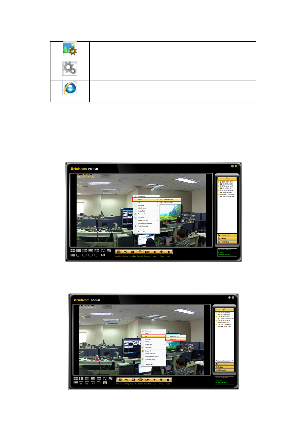
Talk
If there are cameras connected to BRC64, 2-Way audio can be carried out.
Single: Implement 2-Way audio with single camera. Select ‘Single(On/Off)’. Please see
the below photo.
Broadcast: 2-Way audio with several cameras.
42 42
Page 43
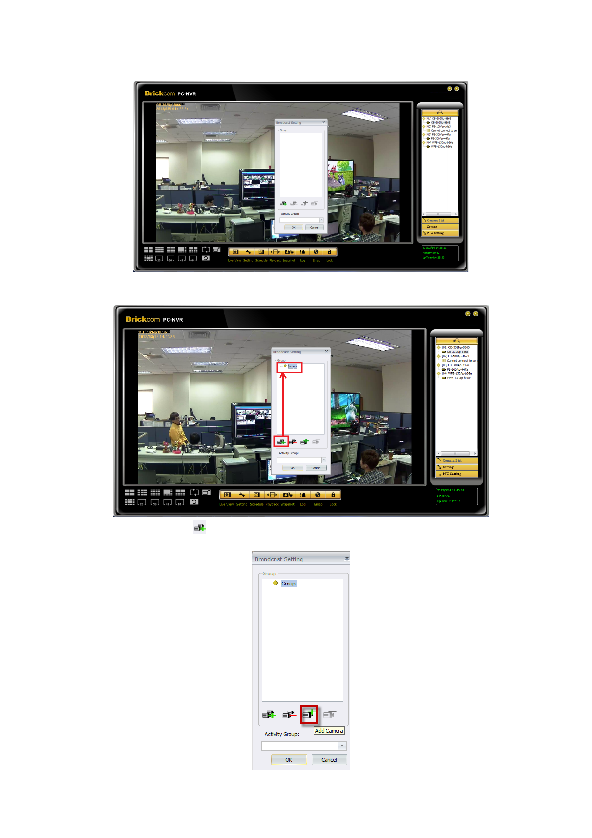
1. Please select Broadcast to start broadcast setting.
2. Please select to create group.
43 43
Page 44
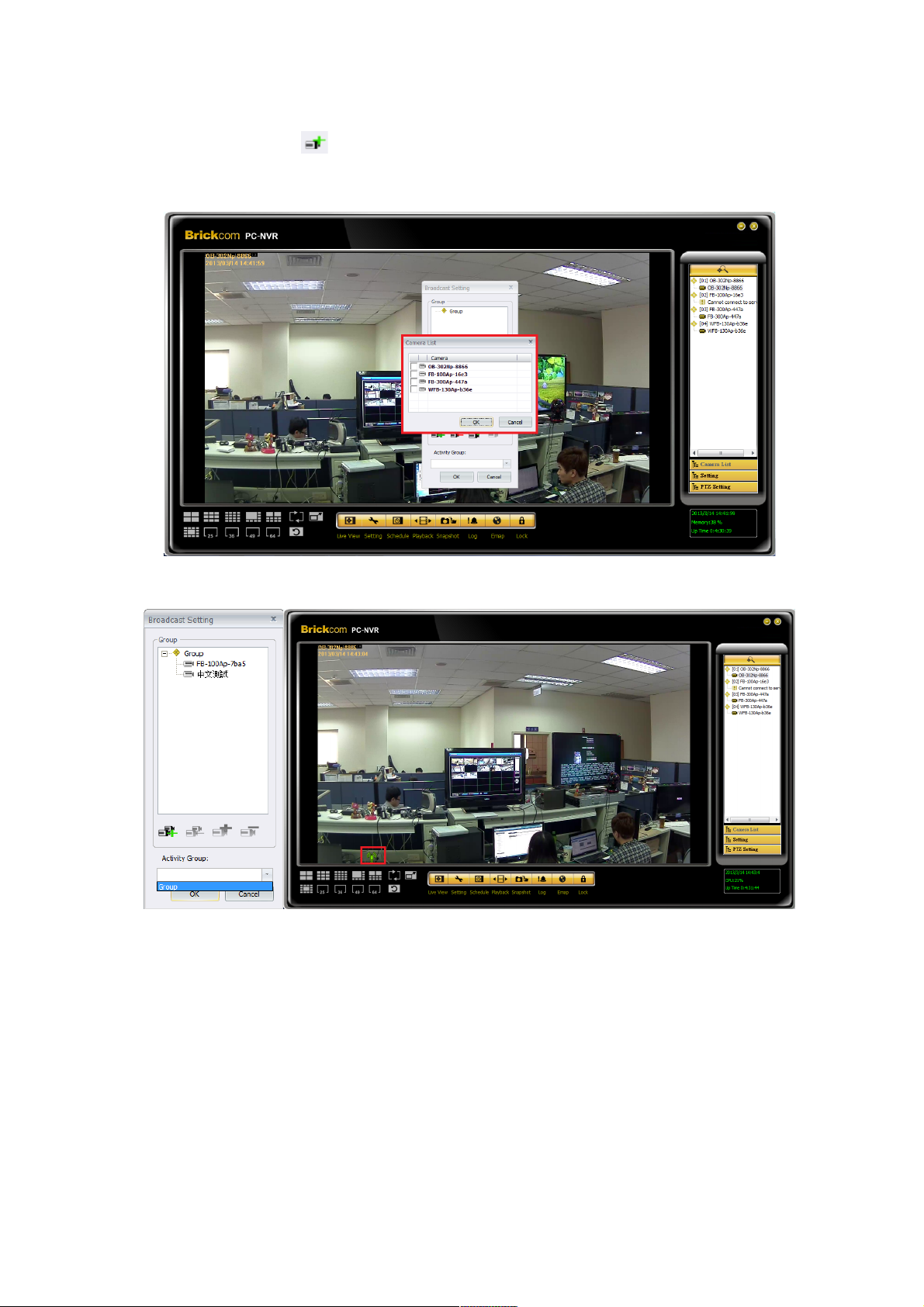
3. Please select to add camera.
4. Add camera to the broadcast list, then press ‘OK’.
5. Select group to start broadcast service, then press ‘OK’.
OSD Settings
‘On-screen display’ displays the camera data, which includes site-name, UPnP name and
Date/Time, of a connected Network Camera on the live view screen. Click to select the
options on the camera setting page or right click on a desired grid and select < OSD
setting > from the drop-down menu.
44 44
Page 45
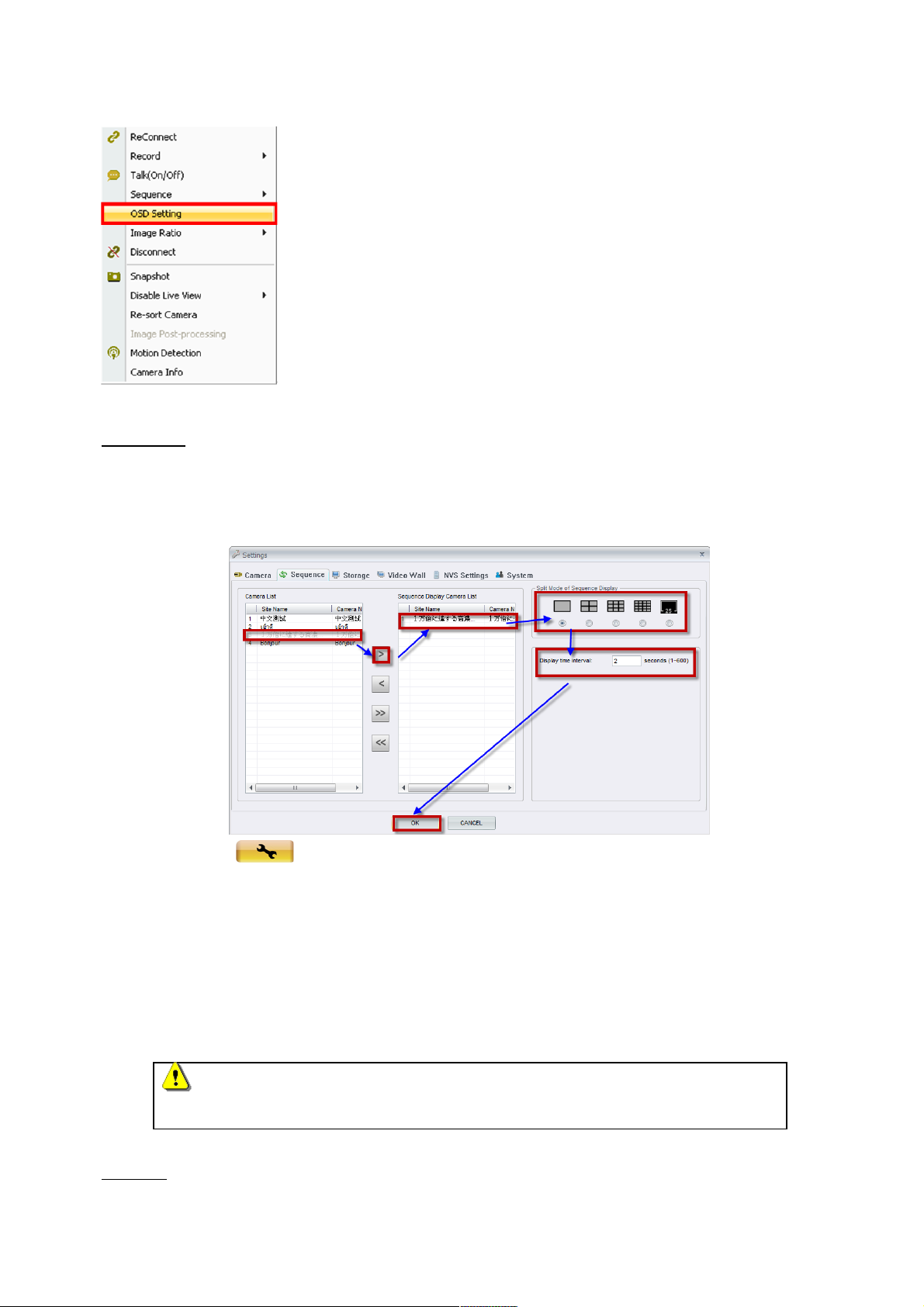
Sequence
This function is used to set the display sequence for live view of the cameras. There are
two ways to add cameras to the sequence.
1. Click on the <Setting> icon and choose <Sequence> to setup the sequence.
Select a camera and move from the ‘Camera List’ to the ‘Sequence Display Camera
List’ in the preferred sequence order. The user can setup the display time interval
(from 1 to 600 seconds) and split mode of sequence display (1*1, 2*2, 3*3, 4*4, and
5*5). Click <OK> to save the settings.
2. Right click on a desired grid and select <Sequence> <Add to Sequence> to add, or
<Remove from Sequence> to remove.
NOTE
When the sequence is added, a capital ‘S’ will be shown on the icon.
Storage
45 45
Page 46
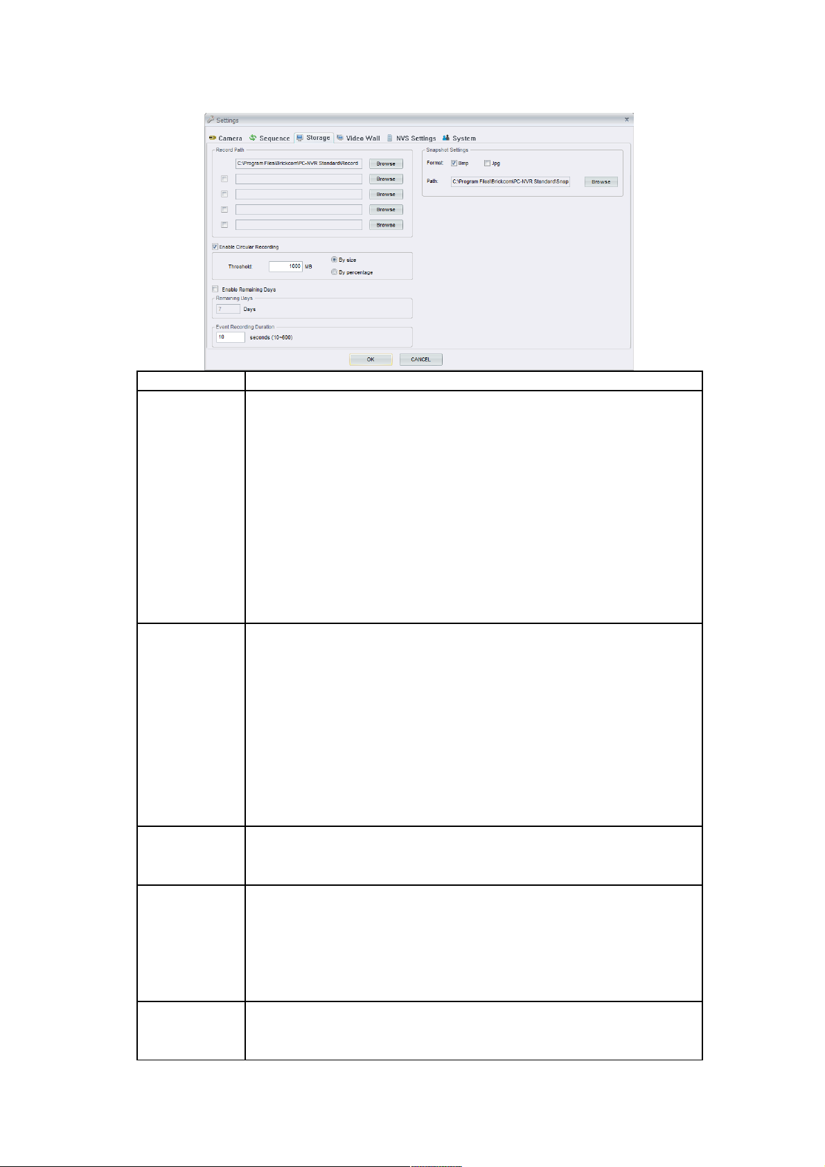
Function Function Description
Record Path The file path menu defines the storage located of recorded
videos and snapshot. It is NOT recommended to use the
default folders.
‘C:\Program Files\Brickcom\BRC64\Record’ is the
default path for recorded videos. The recorded
videos can be stored in more than one folder.
Check the ‘Enable’ box and click <Browse> to set
more destination folders.
Circular
Recording
The Circular is used to adjust the HDD space usage of the
BRC64. If Circular is enabled, then once the free space
remaining in the destination folder falls below the threshold,
the Circular will overwrite the oldest video and snapshot
files in the storage folder with new videos and snapshots
files. The user can adjust the threshold by megabytes or
percentage of the file size.
Remaining
days
Decide the period to store the video clips.
Event
Recording
Duration
When motion detection is enabled, the <Event Recording
Duration> can be used to define the amount of time for
post-event recording. The duration must between 10
seconds to 600 seconds.
Snapshot
Settings
‘C:\Program Files\Brickcom\BRC64\Snapshot’ is the default
path for snapshots.
46 46
Page 47
Click <Browse> to set desired destination folder as shown
below. If the boxes are checked to save snapshots as Bmp
and Jpg, the snapshots will be saved to two folders: one for
Bmp and one for Jpg.
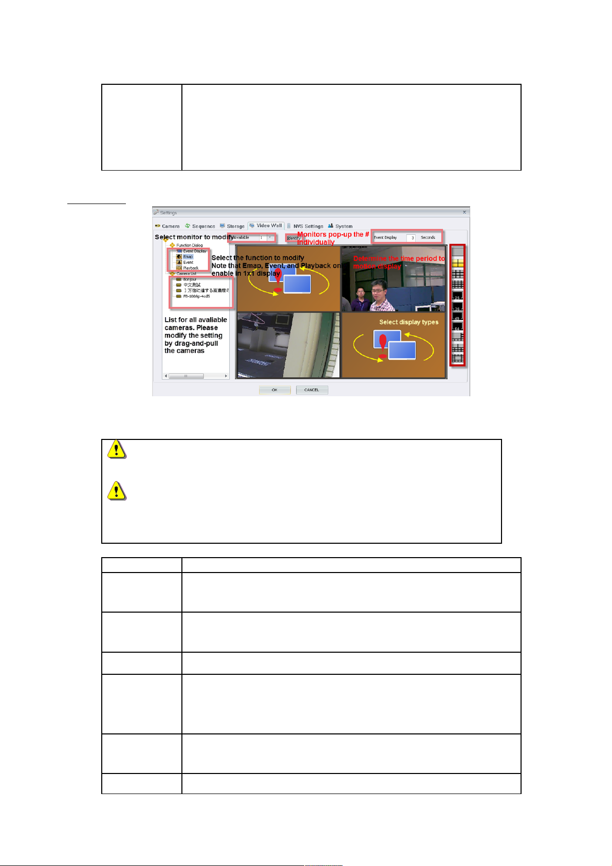
Video Wall
BRC64 allows users to use multiple computer monitors to perform different program.
Display configuration is accessible by selecting button list on the right side.
NOTE1
Please restart BRC64 after changing your device’s resolution.
NOTE2
The setting of Emap, Event, and Playback can only be enabled in 1x1
display.
Function Function Description
Available
Monitor
Select the monitor to modify the setting.
Camera List A list for available cameras, that users can assign these into
schedule by dragging and dropping the mouse.
Identify Pop-up monitor’s number representation.
Event
Display
Period
Determine the time period to motion display.
Function
Dialog
According to user demand, Video Wall supports several functions
to satisfy.
Event Set up events from motion detection to sequence display.
47 47
Page 48
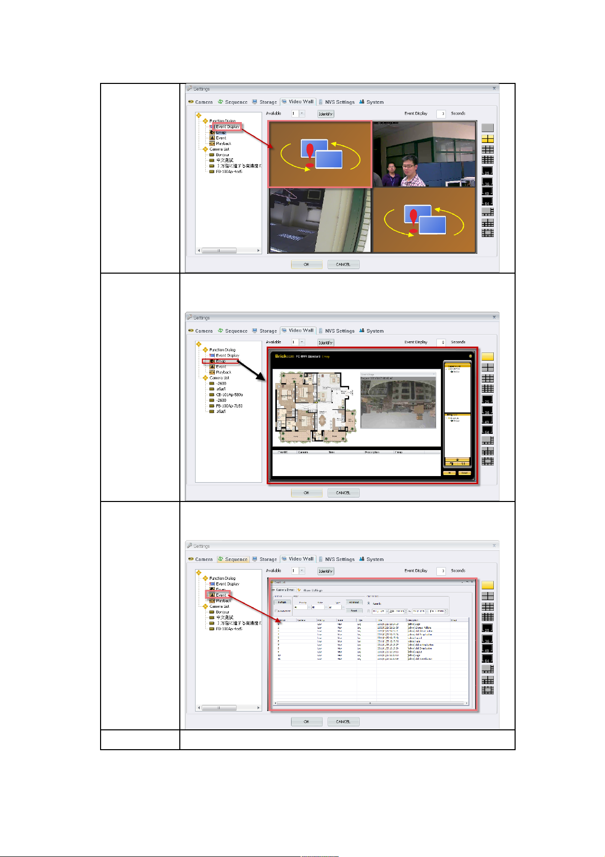
Display
Emap User can arrange monitors to start Emap service to get a clear
picture of the whole environment.
Event User can assign monitors to show & update the latest message
for BRC64
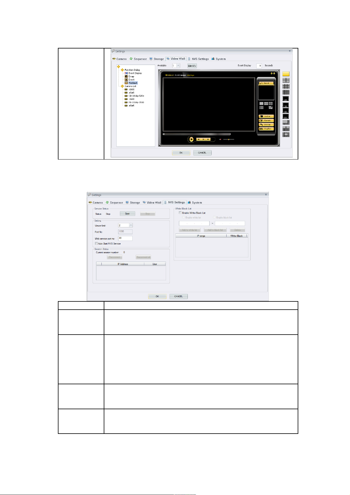
Playback User also can assign monitor for playback service.
48 48
Page 49
.
NVS Setting
Allows another user to monitor immediately by IE browser
Function Function Description
Service
Status
Enable the NVS settings, press <Start> to begin the service
or <Stop> to disable the service.
Setting Modify the maximum connections that can be
accessed.
Modify the port connections that can be accessed.
Enable to start NVS service automatically.
Session
Status
Display connection information.
White/Black
List
Allow/Block specific IP addresses in the service.
Steps to start Remote Liveview & Playback
49 49
Page 50
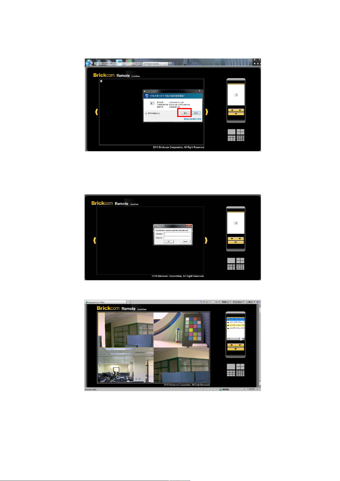
1. Open the IE browser.
2. Input the IP address for BRC64.
3. Agree the ActiveX authorization.
4. Enter the username and password of BRC64.
5. Remote Live View.
Remote Liveview
50 50
Page 51
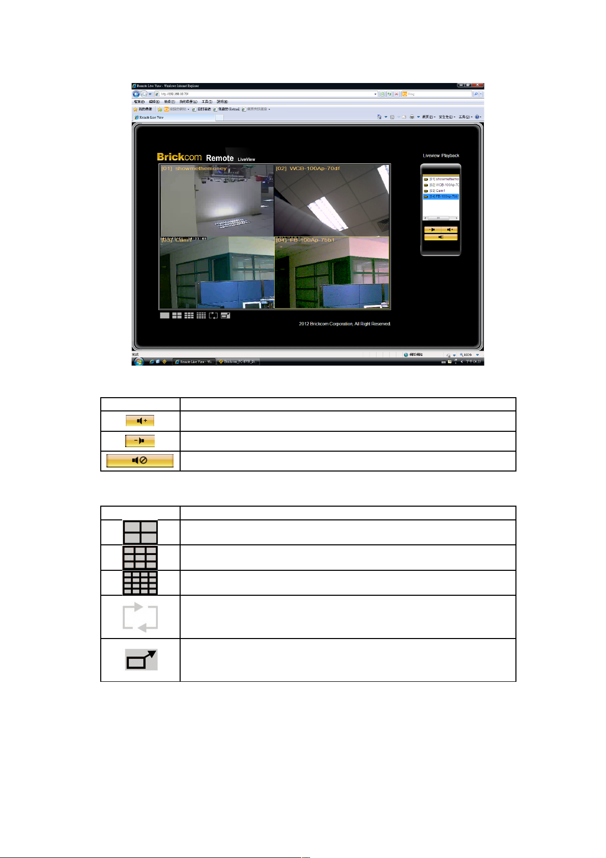
Button Function description
Increase volume
Decrease volume
Turn off audio
Display mode
Button Function description
4-window mode
9-window mode
16-window mode
Sequence: This function is used to set the display
sequence.
Full Screen: Enlarge the viewing window to fit full screen.
Hit <Esc> to exit
Remote Playback
51 51
Page 52
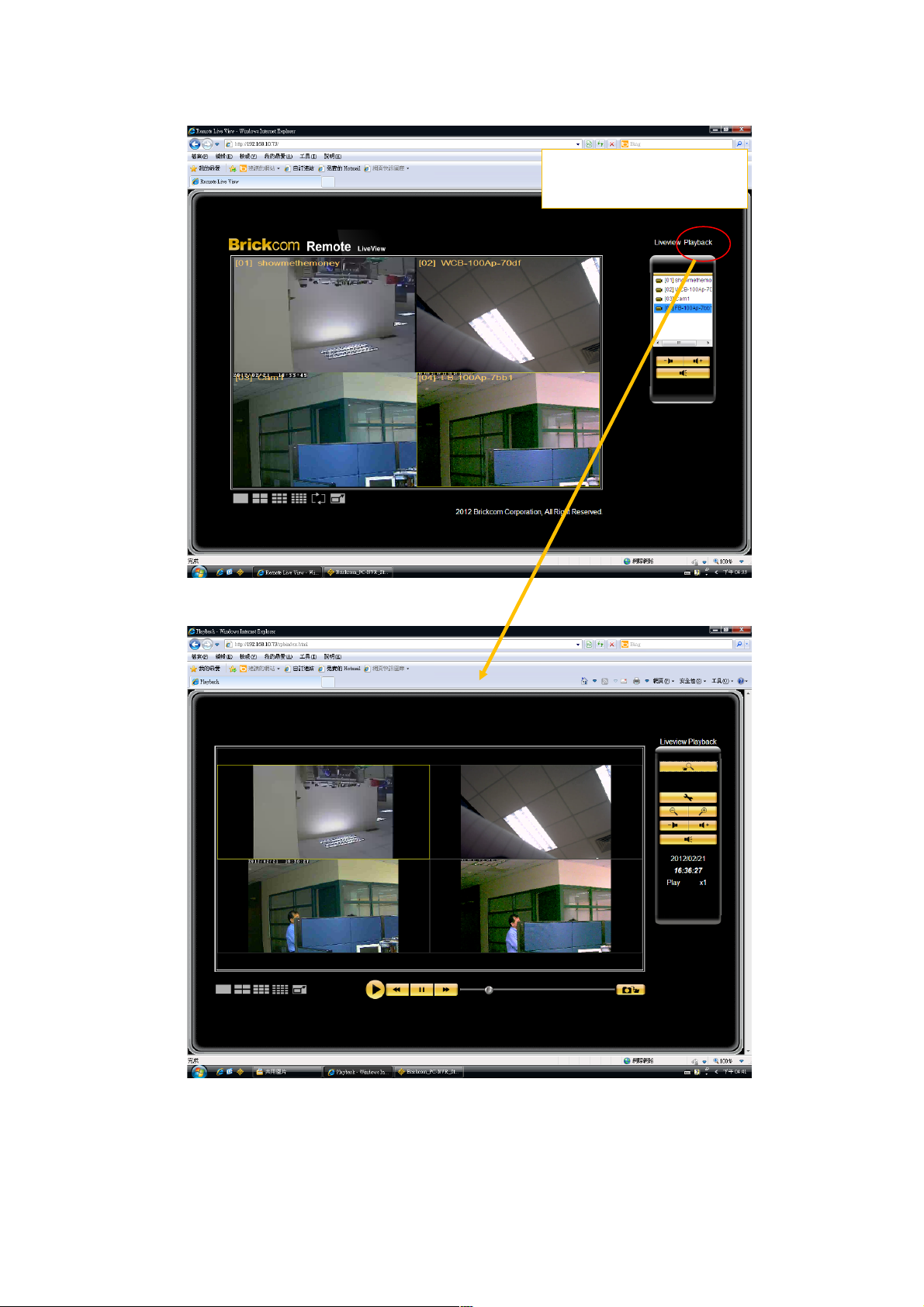
52 52
On LiveView windows ,
click
Playback to enter remote
playback webpage
Page 53
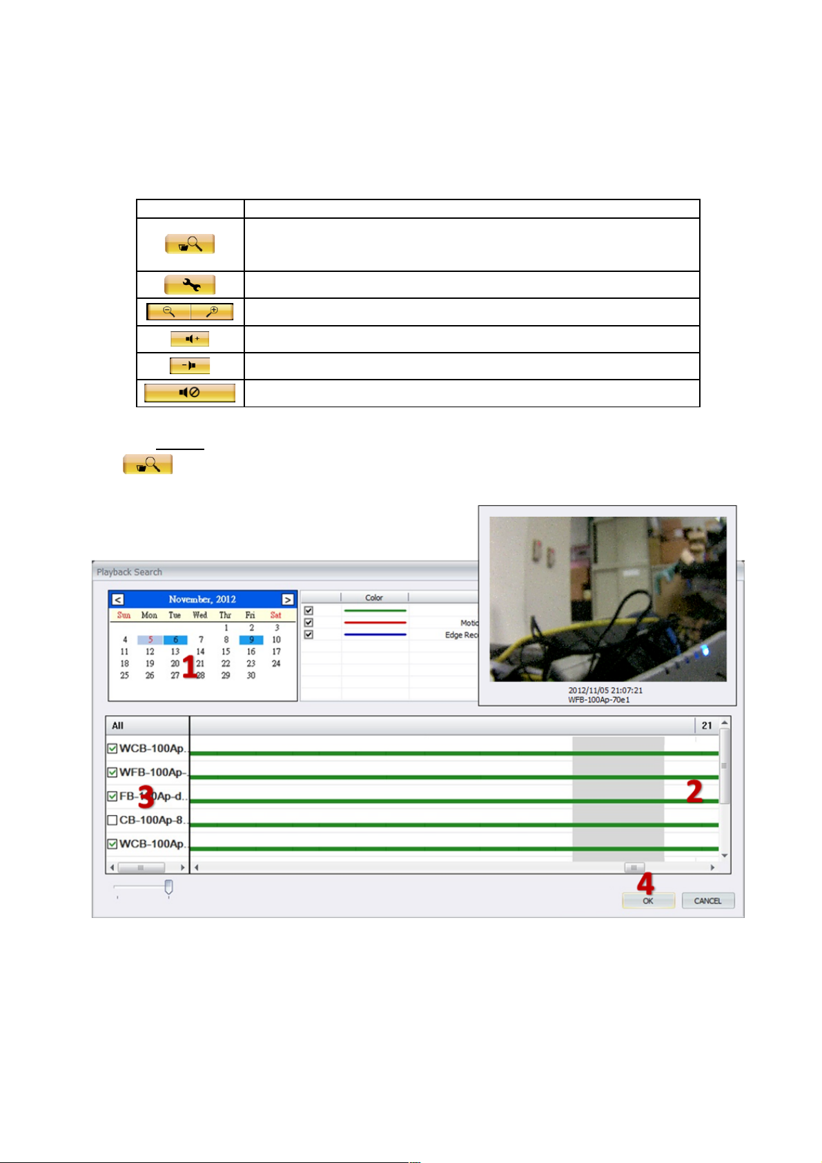
Button Function description
Click <Search Image Files> button to search video clips by event
types or date-time.
<Setting>button
Zoom out/in button
Increase volume
Decrease volume
Turn On / Off the audio output.
Search
Click button,this will pop up a search dialog. There is a preview image window while the
mouse hovers on time footage. Please follow the steps below:
1. Select a specific date on the calendar to playback. Different color are to tell if there are
recording files inside.
2. Select time period. Mouse drag and drop to select a time period. Also, you can use the
mouse to hover on time-line to preview the image
53 53
Page 54
3. Check cameras to insert into the display list.
4. Select mode: Click OK button to display
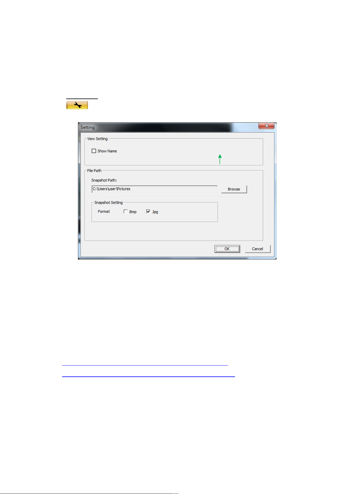
Preference
Click button, Click<Browse>to select snapshot path. In addition, there are 2 formats
for performing snapshots.
The root cause to fail the NVS service:
Reject the installing request for ActiveX authorization.
Forget to close other IE browser pages during installing
process.
Windows needs to be updated. Please follow the below paths
to download the file vcredist_x86.exe.
http://www.microsoft.com/download/en/details.aspx?id=29
http://www.microsoft.com/download/en/details.aspx?id=5582
Please select DOWNLOAD to start & finish the software installing process.
54 54
Page 55
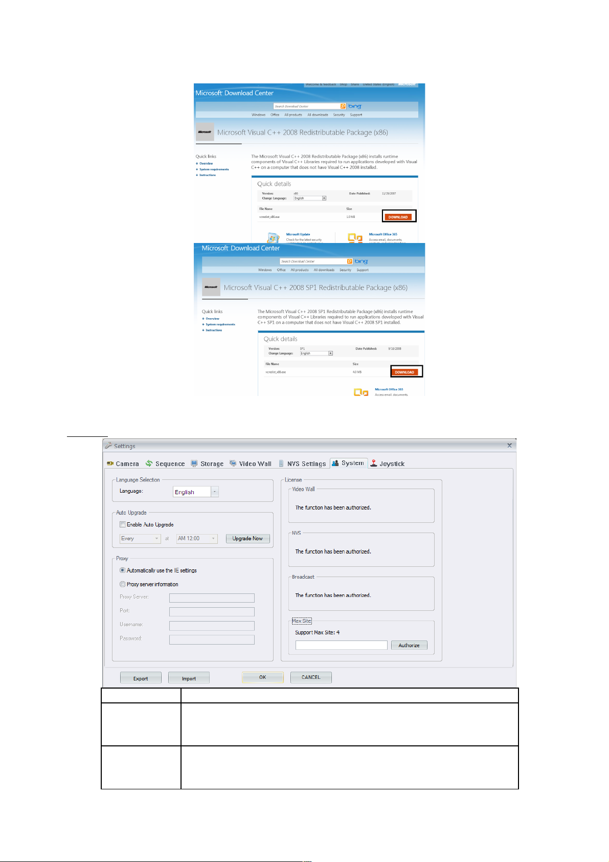
System
Function Function Description
Language
Selection
Select the desired language from the drop-down menu.
Auto Update Modify the regular schedule to update BRC64. Updating
process starts and downloads files automatically at regular
55 55
Page 56
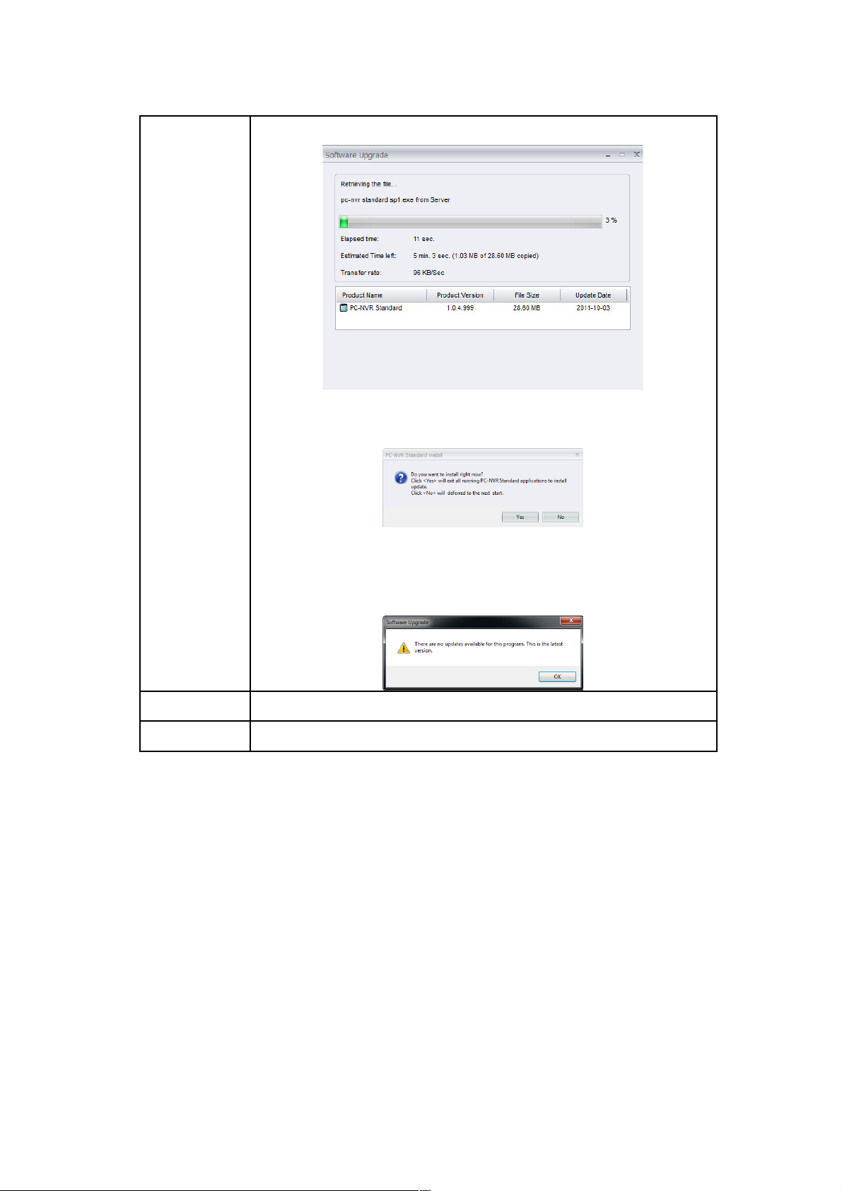
time points. Please see below photo:
After finishing downloading, user will get prompt if new
software update for BRC64 is available.
If no update is available, you will prompt “There are no
updates available for this program. This is the latest
version.”
Proxy Modify proxy setting.
License Display the days remaining to use the specific functions.
Alarm
If there is something wrong with liveview, BRC64 will send first hand information to
default receivers including:
Sounds.
Liveview-Blinking.
E-mail.
Ftp.
How to configure & trigger alarm notification
56 56
Page 57
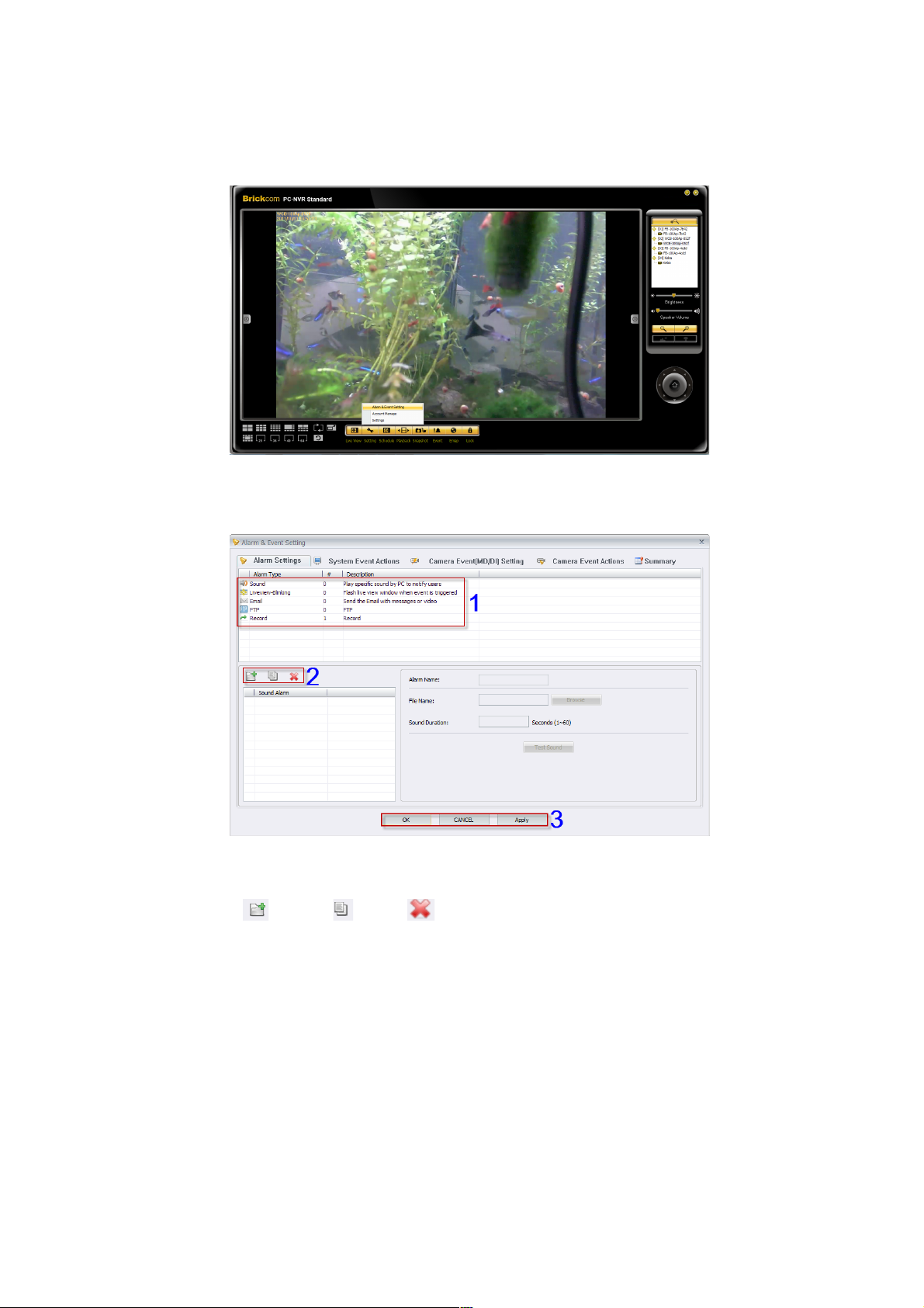
Please refer to the below steps to modify & trigger alarm notification:
1. Please start the alarm setting via ‘Setting->Alarm & Event Setting
Dialog’.
2. Please modify notification types in ‘Alarm Settings’ including ‘Sound’,
‘Liveview-blinking’, ‘Email’ and ‘FTP’. After selecting alarm types, click
<Add> /<Copy> /Delete to create/duplicate/remove alarm
settings.
57 57
Page 58
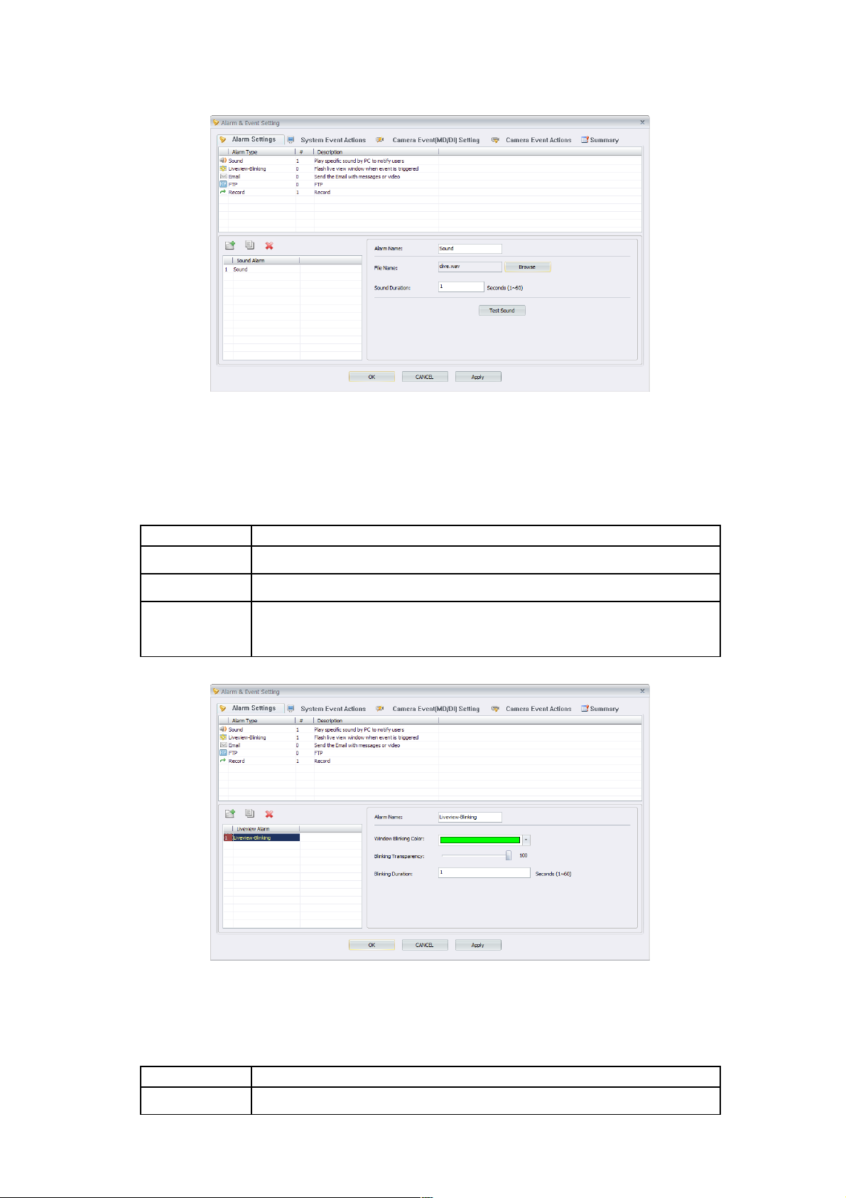
2.1 Detail setting for alarm notifications
2.1.1 Sound
BRC64 will notify users by setting off an audio clip if there is something
wrong with liveview.
Function Function Description
Alarm Name Rename the new alarm file.
File Name Click<Browser> to select the default audio clip.
Sound
Duration
Decide time period to play the audio clip.
2.1.2 Liveview-Blinking
BRC64 will blink the liveview window if there is something wrong with
liveview.
Function Function Description
Alarm Name Rename the new alarm file.
58 58
Page 59
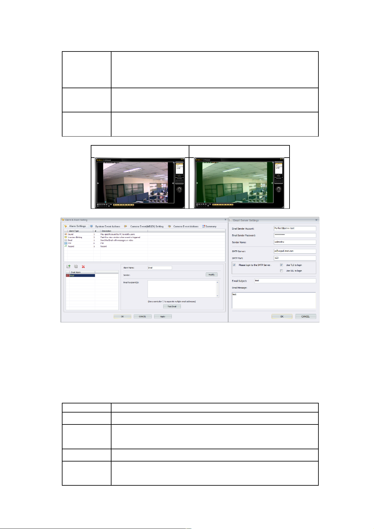
Window
Blinking
Color
Select the color for blinking.
Blinking
Transparency
Transparency modification.
Blinking
Duration
Decide time period for blinking
Non-Blinking Blinking
2.1.3 Email
BRC64 will send messages to default mail address if there is something
wrong with liveview.
Alarm Name-Rename the new alarm file.
Email Recipient-Modify the mail address to send.
Test Email-Pre-Test the prior setting.
Function Function Description
Alarm Name Rename the new alarm file.
Email
Recipient
Modify the mail address to send.
Test Email Pre-Test the prior setting.
Modify
Sending
According to different Email address, configure the server setting
for delivering.
59 59
Page 60
connection
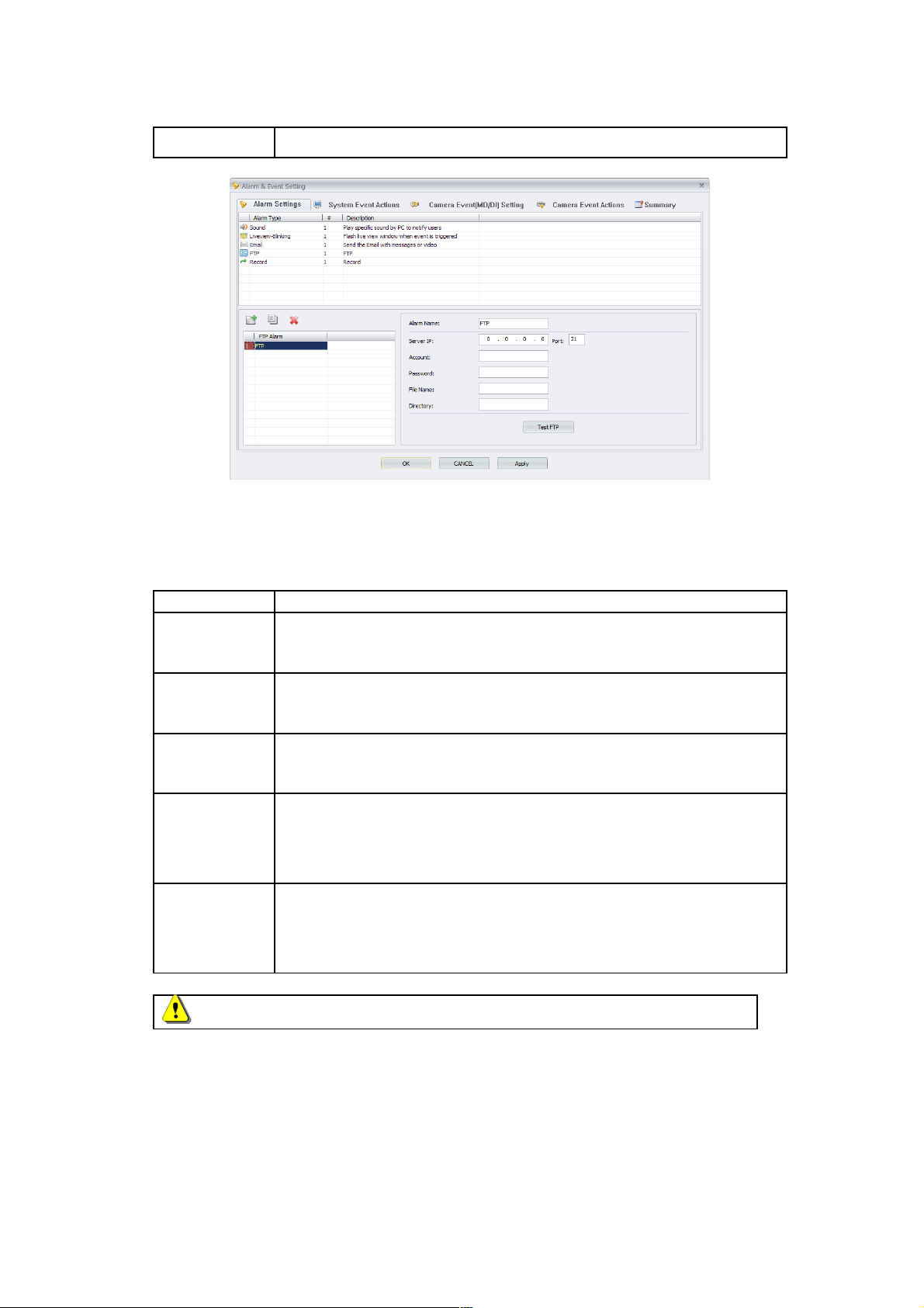
2.1.4 FTP
BRC64 will send snapshots to the default FTP address if there is something
wrong with liveview.
Function Function Description
FTP Alarm
Name
Rename the new alarm file
Server IP &
Port
Modify the IP address and accessible port to connect the Ftp
server.
Account &
Password
Modify Account & Password to login.
File Name Rename the storage file to save & upload. For example, the file
name will be Snapshot_Test_Time if input ‘Test’ in File Name
column.
Directory Modify the default subfolders position to upload. For example, the
default subfolder position to upload will be ‘Test’ if input ‘//Test’ in
Directory column.
NOTE-It is necessary to input ‘//’ in the Directory column.
60 60
Page 61
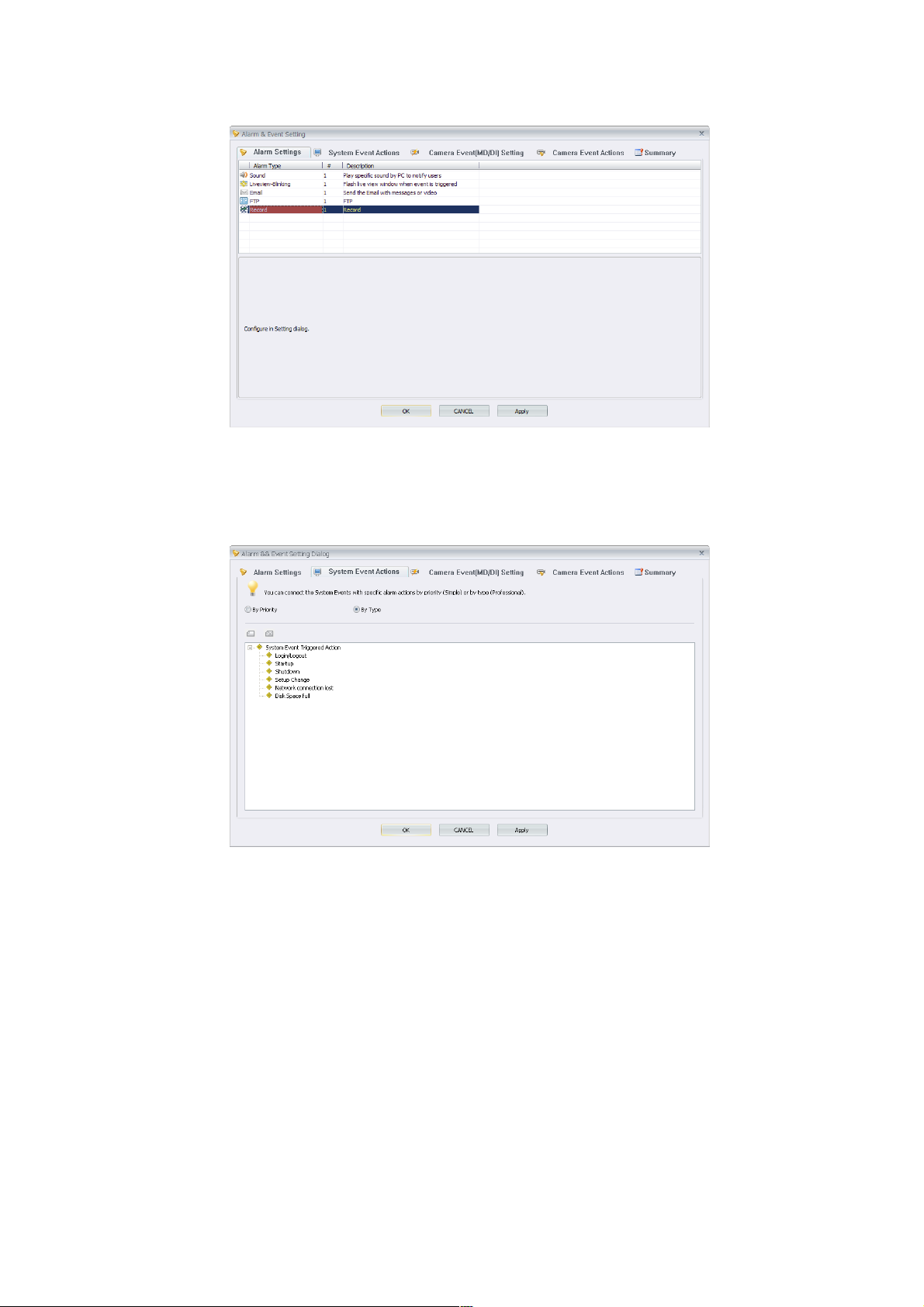
2.1.5 Record
BRC64 will start the recording process if there is something wrong
with live view.
2.2 According to the actual needs, assign cameras to implement alarm
notifications in ‘Camera Event Setting’ or choose the system event
notification service in ‘System Event Actions’.
2.3 Detail setting for System Event Actions.
BRC64 will notify users if specific events happen during BRC64 operation.
Specific events include login, logout, shutdown, etc.
61 61
Page 62
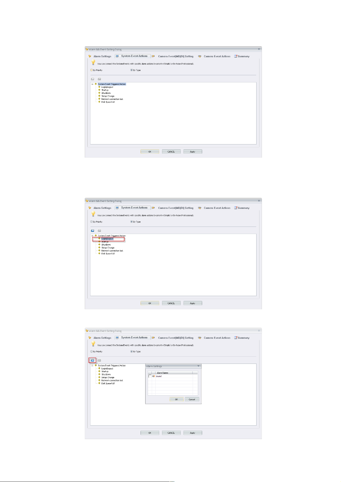
3.1.1 Please choose to connect by ‘Priority’ or by ‘Type’ for alarm
notification. Priority mode is available if BRC64 has been configured with
priority to system events. Default modification is to connect by type.
3.1.2 Please select system event to trigger alarm notification.
62 62
Page 63
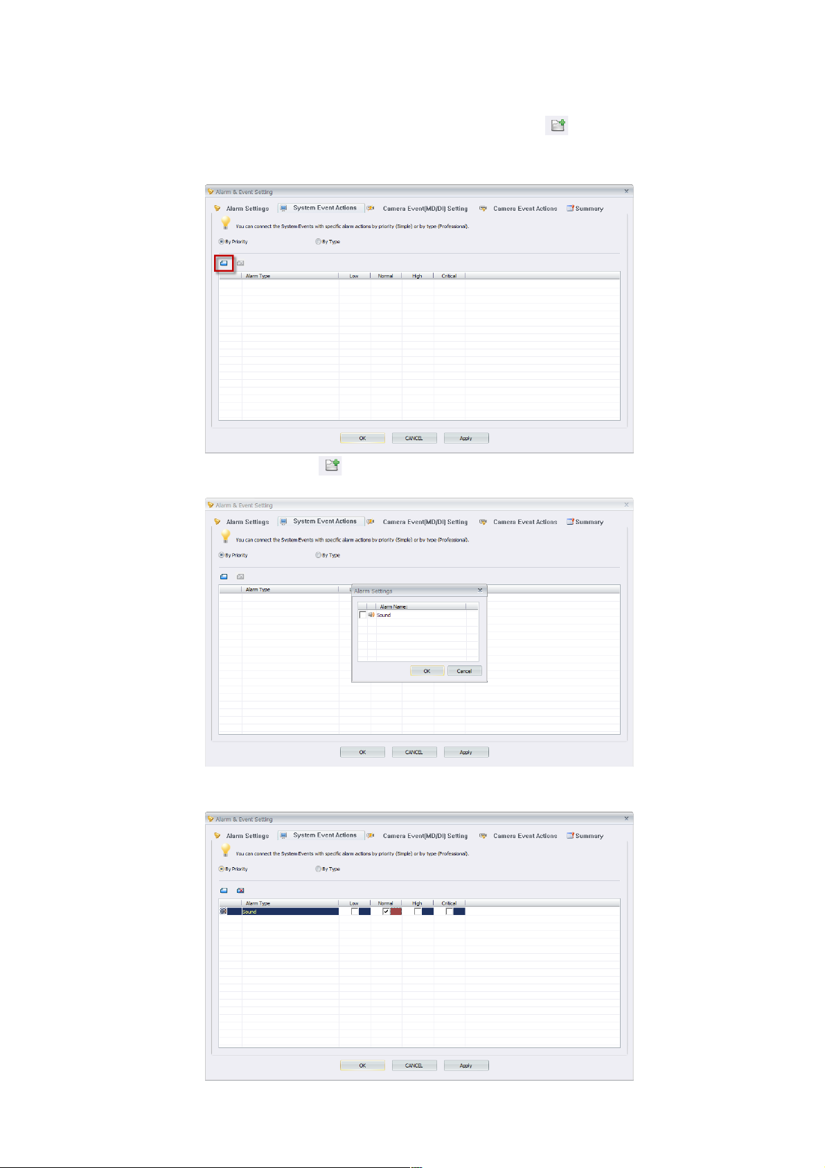
3.1.3 Please assign alarm notification by pressing <add> button, then
select <OK> to finish the setting.
3.1.4 Please click <Add> button to create new alarm type.
3.1.5 Select alarm name to carry out notification, then press <OK>.
63 63
Page 64
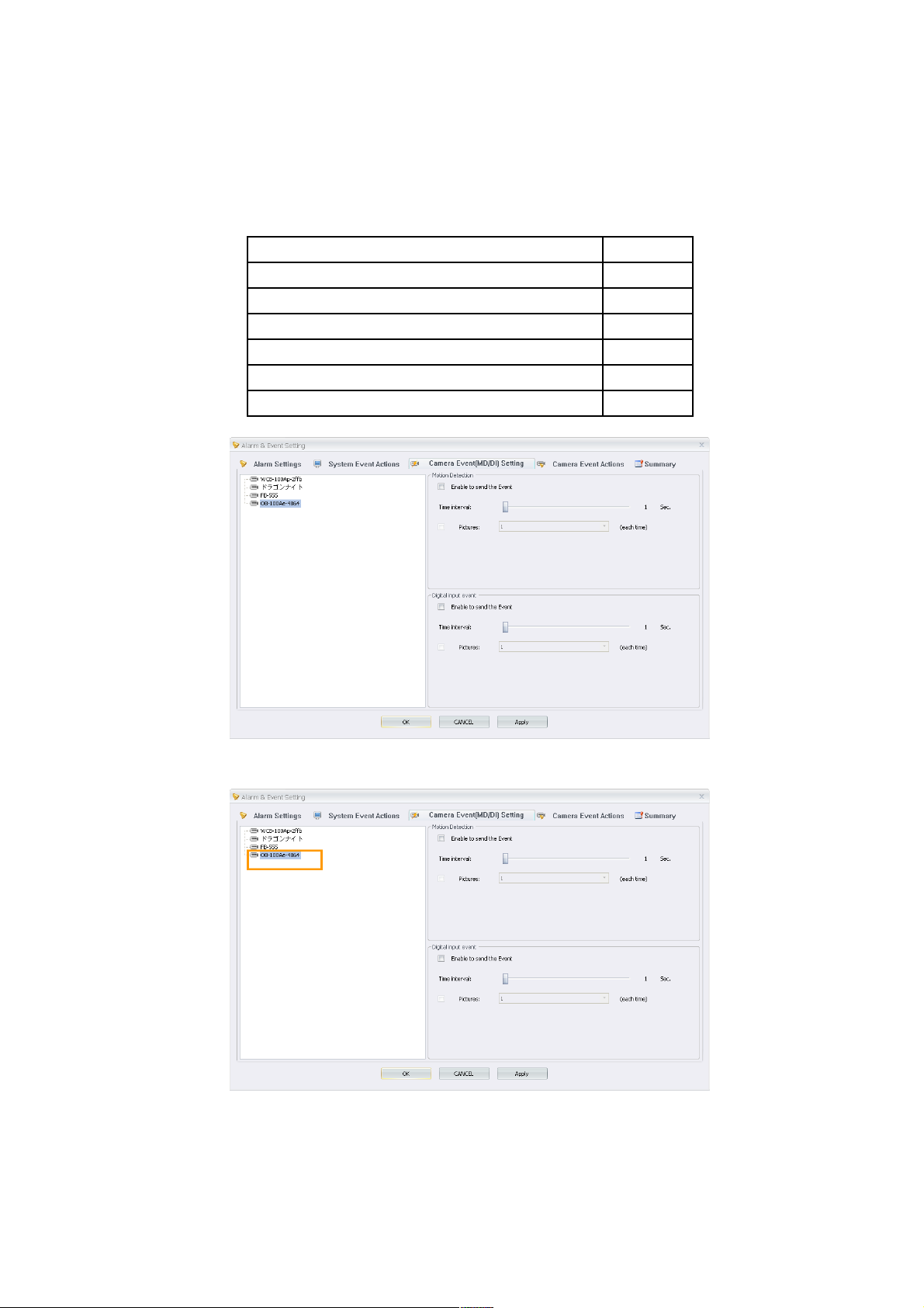
3.1.6 According to different system events, set up default priority to alarm
types individually.
Please see below the chart for default priority rank for event type:
Default priority rank for Event type:
Login/Logout: Low
Startup: Low
Shutdown: Low
Setup Change: Normal
Disk Space Exhausted: Normal
Network Loss: High
4.1 Camera Event[MD/DI] Setting.
4.2 Please select a camera to start individual alarm event report.
4.2.1 Please select event types to trigger alarm notification service including motion
detection and digital input event. Furthermore, it is accessible to advanced
setting including modifying the time interval to report MD/DI event and selecting
64 64
Page 65
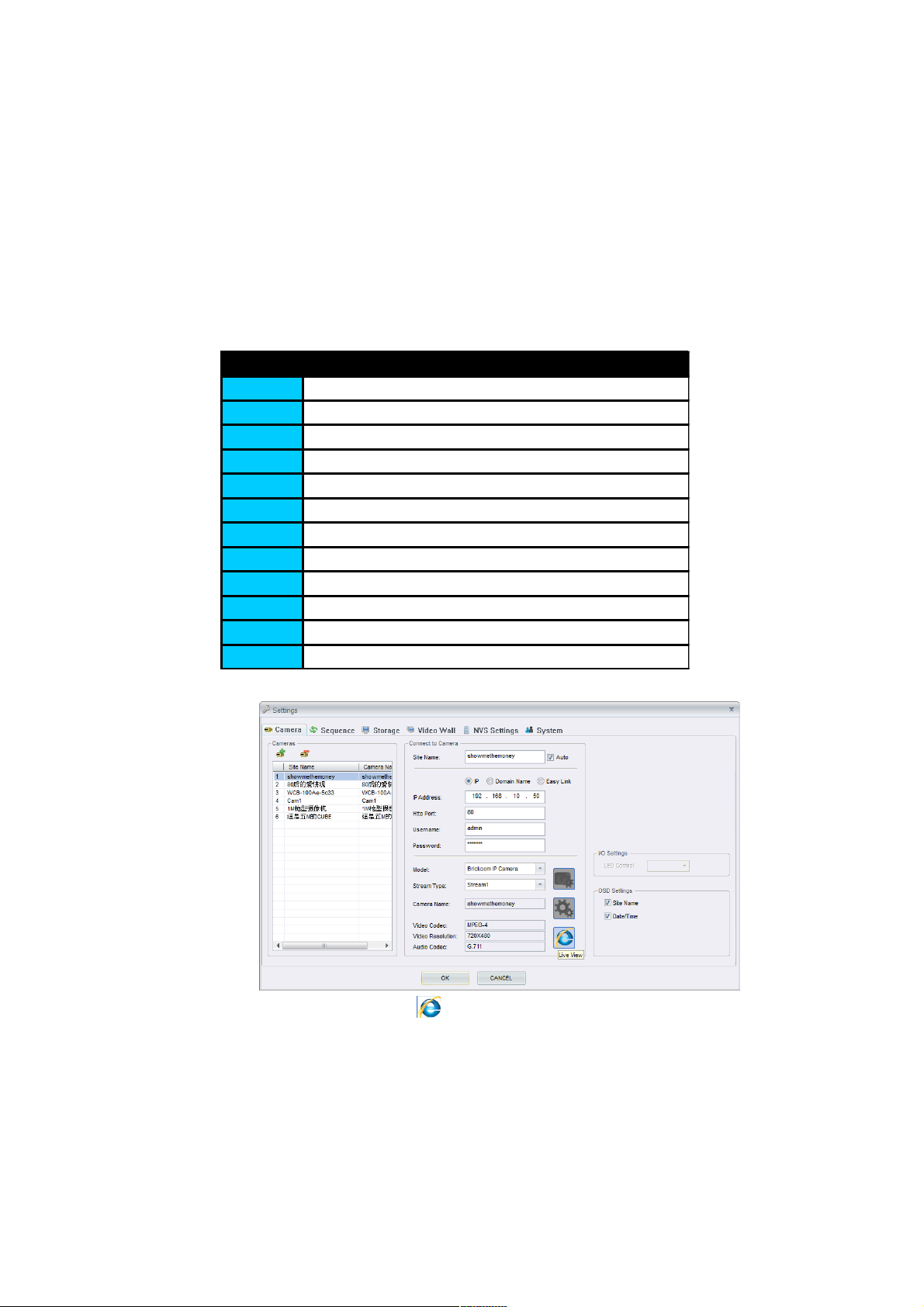
the snapshot frequency per notification.
4.2.1.1 Users can modify Digital Input Event service and Camera status by hot-
key such as F5,F6,F7,F8,Ctrl+F5,Ctrl+F6,Ctrl+F7,and Ctrl+F8.
Alarm for Digital Input Event Service will trigger if the status between
external device attached to the camera and that of the camera is the
same. The following steps are how to get the digital input status of
camera.
Hotkey Description
F2 Enable all Record
F3 Enable all MD Record
F4 Disable all Record
F5 Set selected camera DI Status to Low
F6 Set selected camera DI Status to High
F7 Set all cameras DI Status to Low
F8 Set all cameras DI Status to High
Ctrl+F5 Set selected camera DI detection disable
Ctrl+F6 Set selected camera DI detection enable
Ctrl+F7 Set all cameras DI detection disable
Ctrl+F8 Set all cameras DI detection enable
F9 Show DI Status in Video Frame(10 Sec)
4.2.1.2 Click the <Live View> button to connect the setting dialog page for
camera via the path “Setting→Settings→Cameras.”
65 65
Page 66
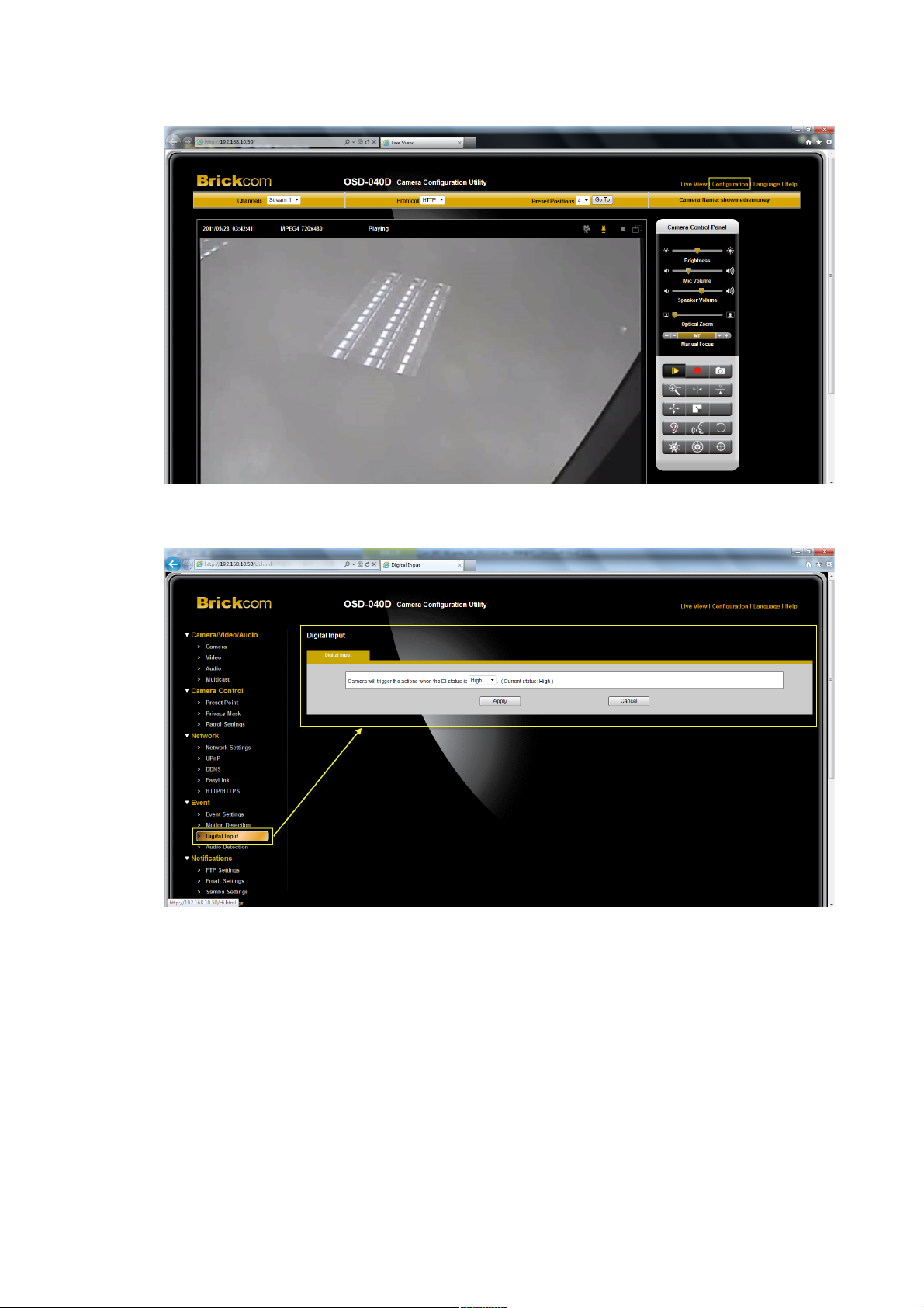
4.2.1.3 Please select <Configuration>.
4.3 Please check the “Current status” for external device attached to the camera
via the path “Event→Digital Input→DI/DO”.
66 66
Page 67
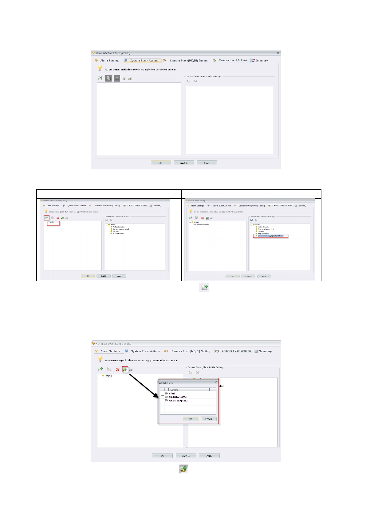
5.1 Please trigger alarm notifications in Camera Event Actions.
Normal Event Digital Input Event
5.2 Please create new profile by pressing <New> button. If you have already
triggered Digital Input Event service for some cameras in Camera Event[MD/DI]
Setting(4.1), the Digital Input Event will appear in Camera Event & Alarm Profile
Settings for advanced configuration named as “CameraName_Digital Input Event”.
5.3 Please add camera by pressing <Add> button.
67 67
Page 68
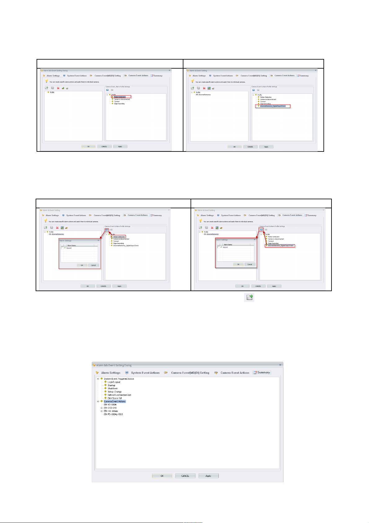
Normal Event Digital Input Event
5.4 Select profile’s system event in Camera Event Alarm Profile Settings. Digital Input
Event for individual camera is available in Camera Event & Alarm Profile Settings
named as ‘CameraName_Digital Input Event’.
Normal Event Digital Input Event
5.5 Assign actions to alarm notification by pressing <Add> button. Please press
Apply & OK to finish alarm notification settings. Prior setting will carry out immediately
if related detections start the service.
Summary
Detailed event information to BRC64.
68 68
Page 69
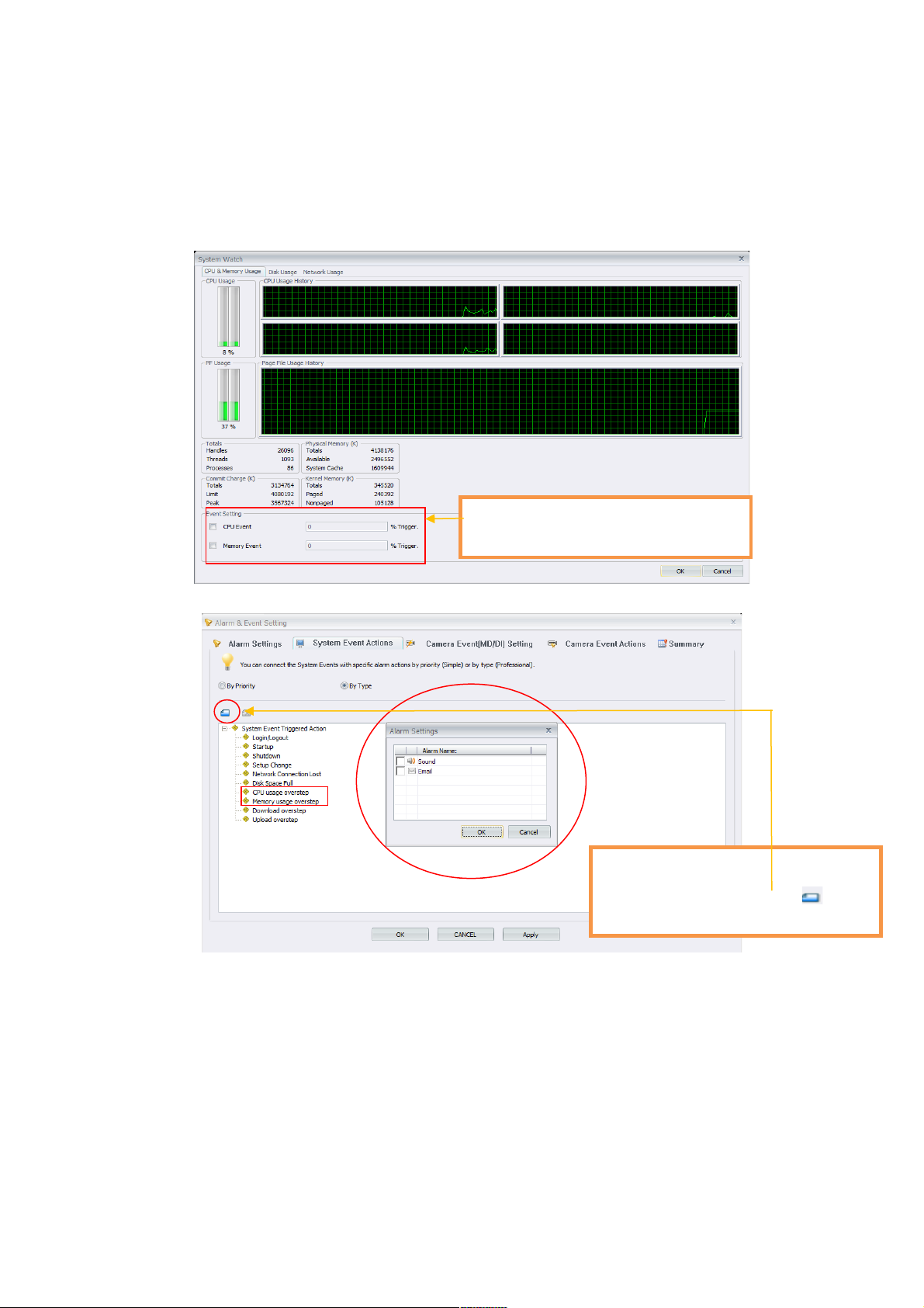
System Information
1.1 CPU & Memory usage
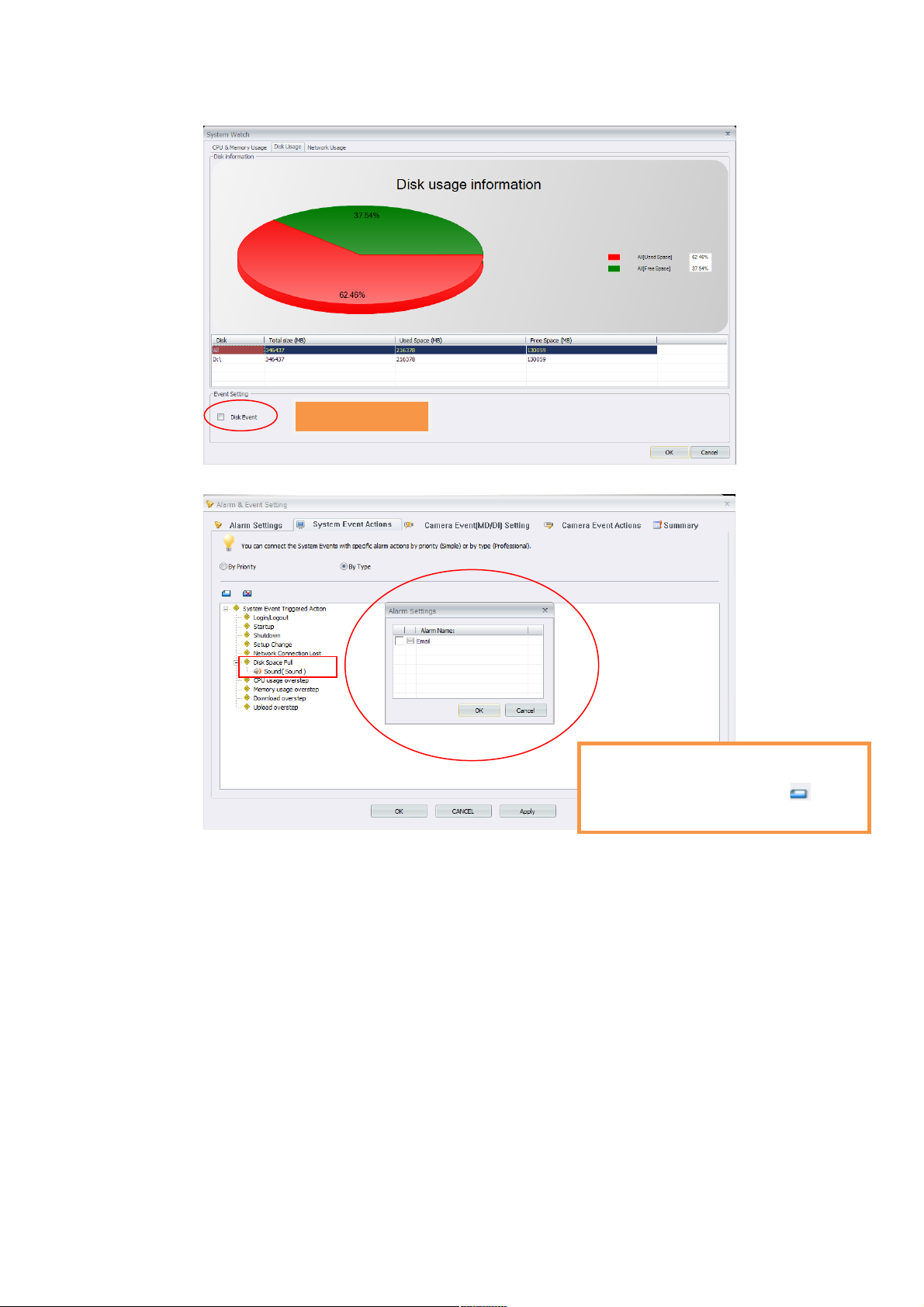
1.2 Disk Usage
69 69
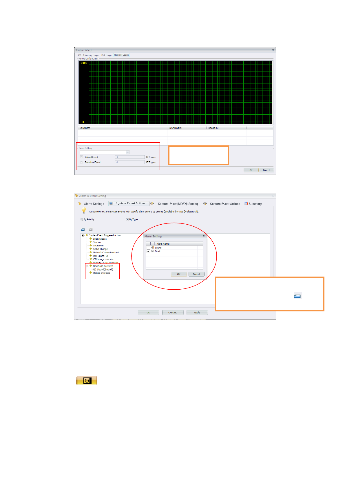
event trigger sources which are CPU
event and memory event respectively.
[Event Setting] : There are 2 system
[Set action triggered by event] :
[Alarm&Event Setting]→[System Event
Actions],select system action and click ,it will
popup alarm settings dialog.
Page 70
1.3 Network Usage
70 70
[Set HD event]
[Set action triggered by event] :
[Alarm&Event Setting]→[System Event
Actions],select system action and click ,it will
popup alarm settings dialog.
Page 71
Schedule Record
Click on the <Schedule record> icon and the figure below will be displayed.
The user can schedule specific times for the camera to record videos.
71 71
[upload Event] &
[download Event]
[Set action triggered by event] :
[Alarm&Event Setting]→[System Event
Actions],select system action and click , it will
popup alarm settings dialog.
Page 72
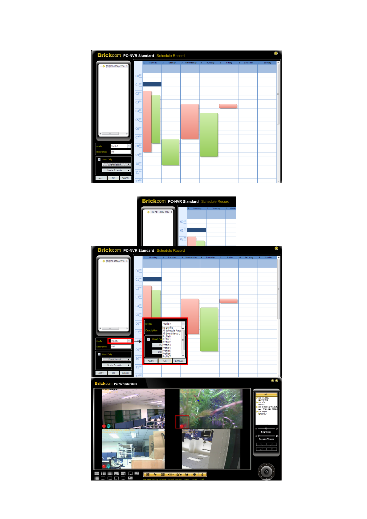
Create a recording schedule for a camera:
72 72
Page 73
1. Select the desired camera.
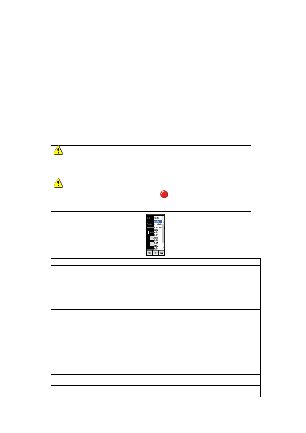
2. Select a profile from the ‘Profile’ drop-down menu. Enter a
description for the profile.
3. Click and drag the mouse on the time frame table to schedule
specific times for the camera to record video.
4. After finishing creating a recording schedule for the desired camera,
click <Apply> to save and keep editing the schedule record setting for
other cameras or click <OK> to save and exit the Schedule Record.
5. Recorded files will be saved to the default folder ‘\BRC64\Record\’.
NOTE1
When a profile is created, it can be used by other cameras by
repeating step one and choosing the desired profile.
NOTE2
When the sites are being recorded, a will be displayed on the live
view main window of the site.
Function Function Description
Read Only Allows the user to read the schedule only.
Edit Schedule
Select All
Period
Schedule will be set to record normal and event videos at
all times.
Schedule
Record
Schedule to record only the normal videos within the
selected time frame.
All Event
Record
Schedule to record only the event videos all the times.
Event
Record
Schedule to record only the event videos within the selected
time frame.
Delete Schedule
Delete One Select to manually clear the schedule setting.
73 73
Page 74
Period
Delete All
Period
Select to clear all the schedule settings.
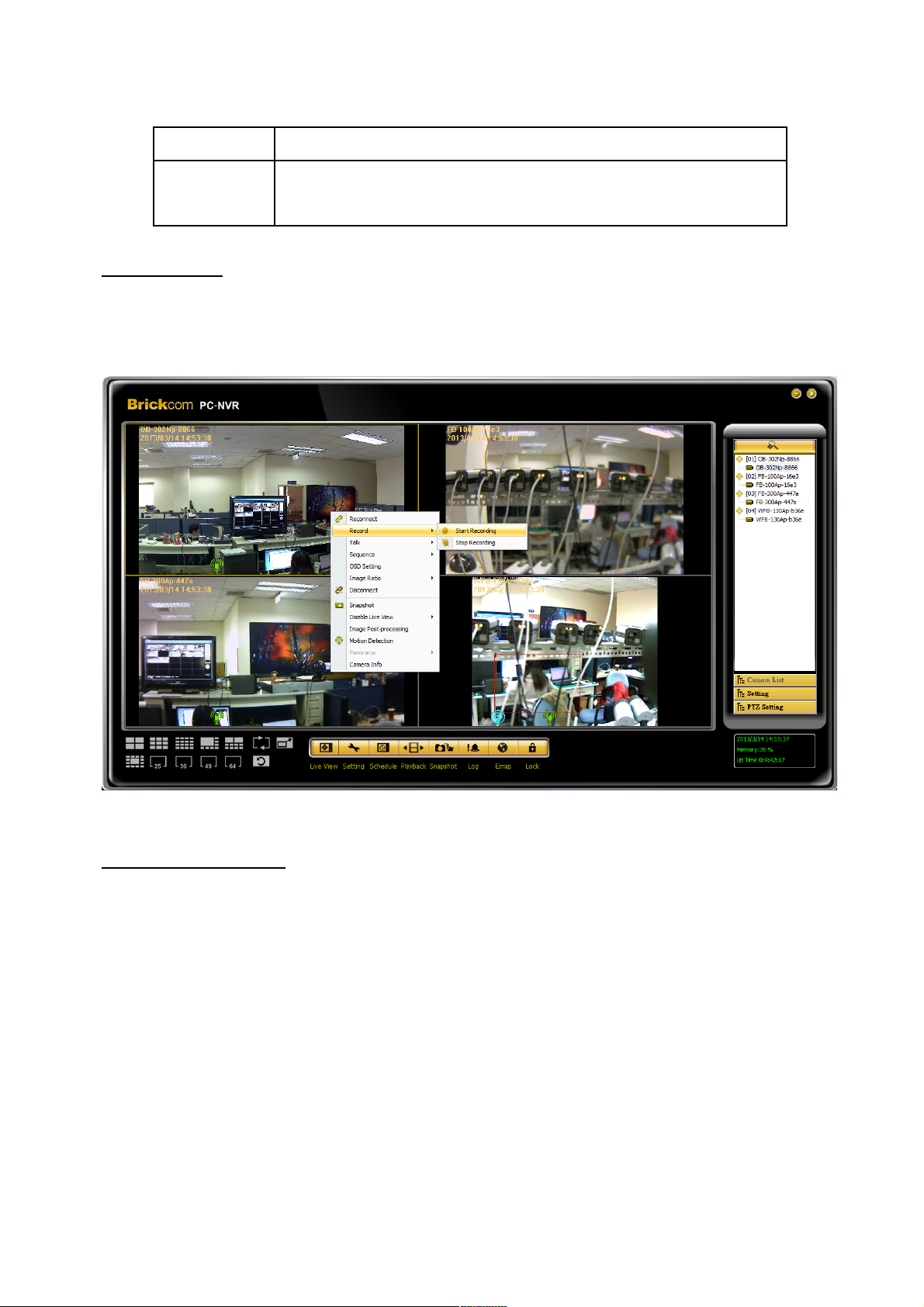
Instant Record
While the videos are scheduled to record, the user can choose to instantly record live
video clips. Right click on a desired grid and select <Start Recording> to start recording
and <Stop Recording> to stop recording.
Adjust the display size
The user can adjust the display size of the Live View window by right pressing on the
window to display the camera control menu. Select <Image Ratio> to adjust the size.
The image ratio includes: Original, Fit, Original all, and Fit all.
74 74
Page 75
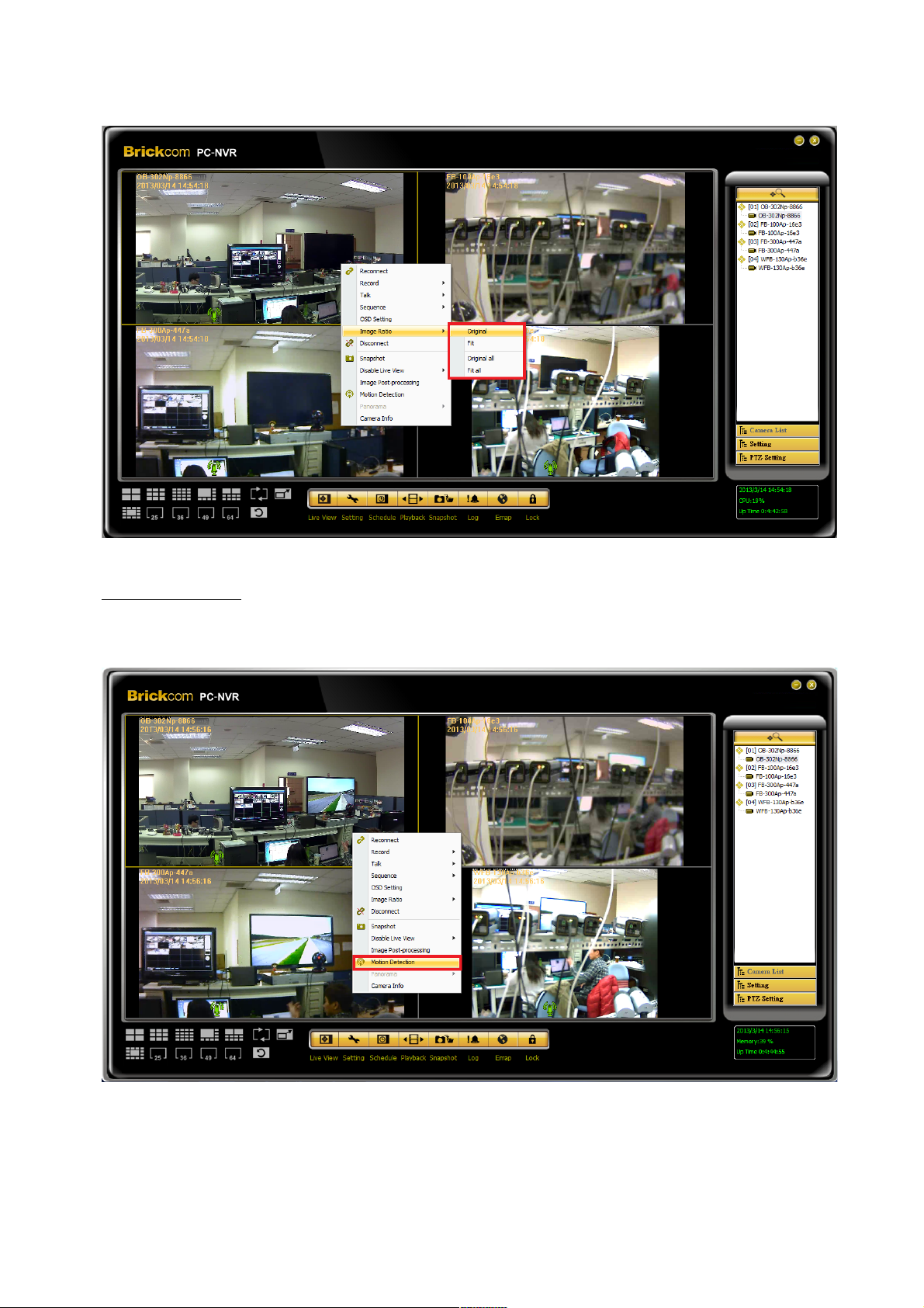
Motion Detection
Users can setup a camera to record motion detection at any site. Right click on a desired
grid and select <Motion Detection> from the pull down menu.
Please see below pictures for the motion detection settings window. Under ‘ Detection
Region’, users can click <ALL> to monitor the entire screen or click <Regional> to
monitor up to eight individual regions. A blue grid will appear on the screen and the user
75 75
Page 76
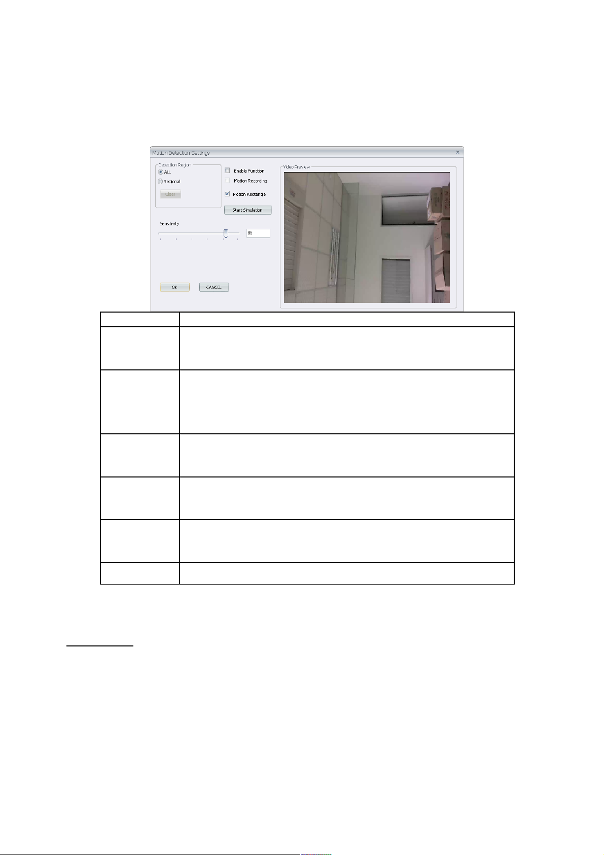
can adjust the size. To delete, select desired grids and click on the < Clear> button to
delete all selected areas. Alternatively, right click on any selected area to delete it
individually.
Function Function Description
Enable
Function
Check to begin monitoring motion detection.
Motion
Recording
Check to record an event video when motion is detected.
The length of event video can be set by going to <Event
Recording Duration> which is under System Setting
Motion
Rectangle
Show the detection area while event is happening.
Start
Simulation
Click to simulate motion detection. As shown above, red
boxes will mark when motion is detected in an area.
Stop
Simulation
Click to stop the simulation.
Sensitivity Setup a desired sensitivity level from 0 to 100.
Click on <OK> to apply the settings, or click on <Cancel> to disregard and return to Live
mode. The live monitoring screen will not show the colored motion detection boxes.
Camera Info
The Camera Info can be viewed in BRC64. Right click on any desired grid and select
<Camera Info.> from the pull down menu to view the information. Refer to the following
for example:
76 76
Page 77
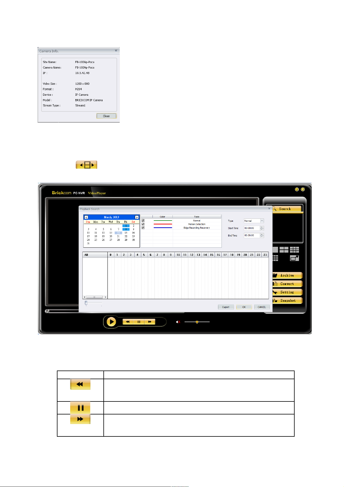
Playback
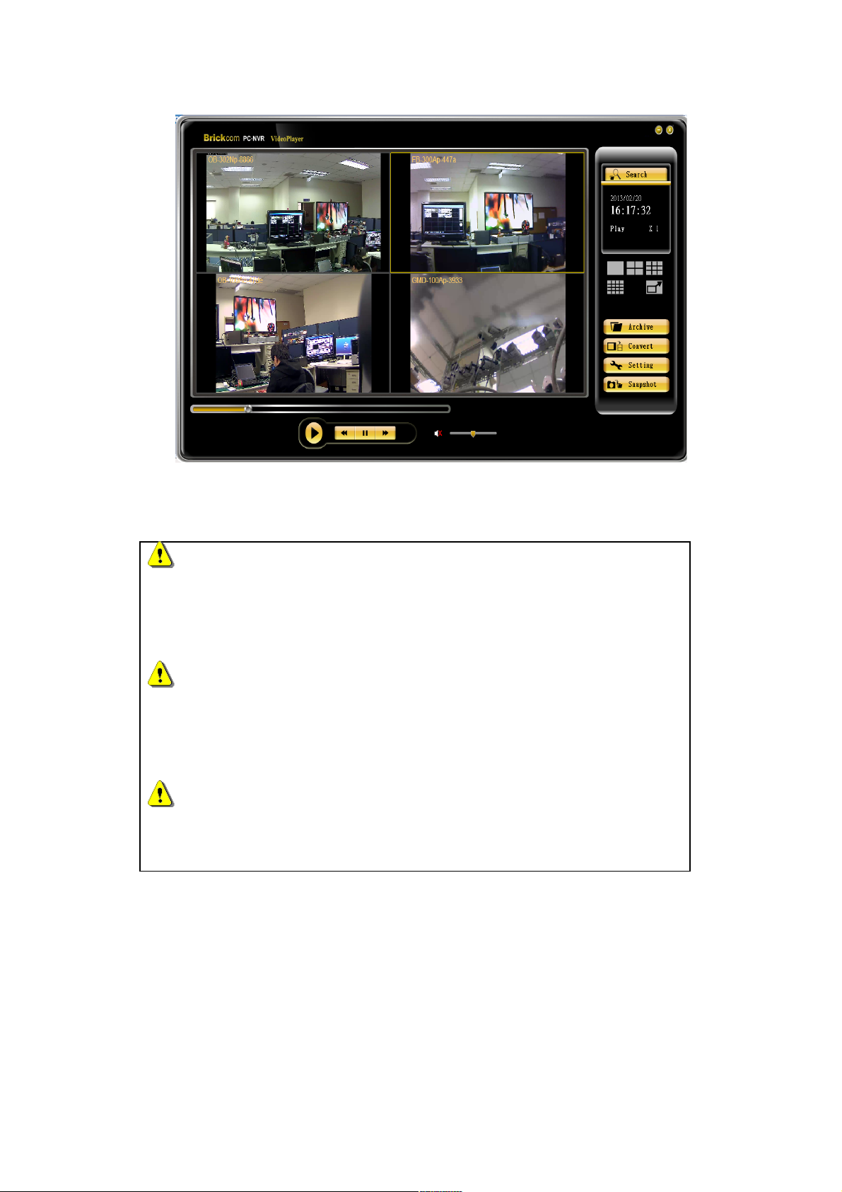
Click on the <Playback> icon, the figure below will be displayed.
This function allows the user to retrieve and play multi-channel videos stored on the
HDD.
Function Function Description
Click <Rewind> to play backward. In pause mode, time point
returns to 1 second ago per click.
Pause.
Click <Fast Forward> to change playback speed. In pause mode,
time point returns to 1 fps ago per click.
77 77
Page 78
Play.
Turn On / Off the audio output.
Click <Search Image Files> button to search video clips by event
types or date-time.
Drag-and-drop the tool bar to adjust audio volume.
Drag-and-drop the tool bar to change the start time.
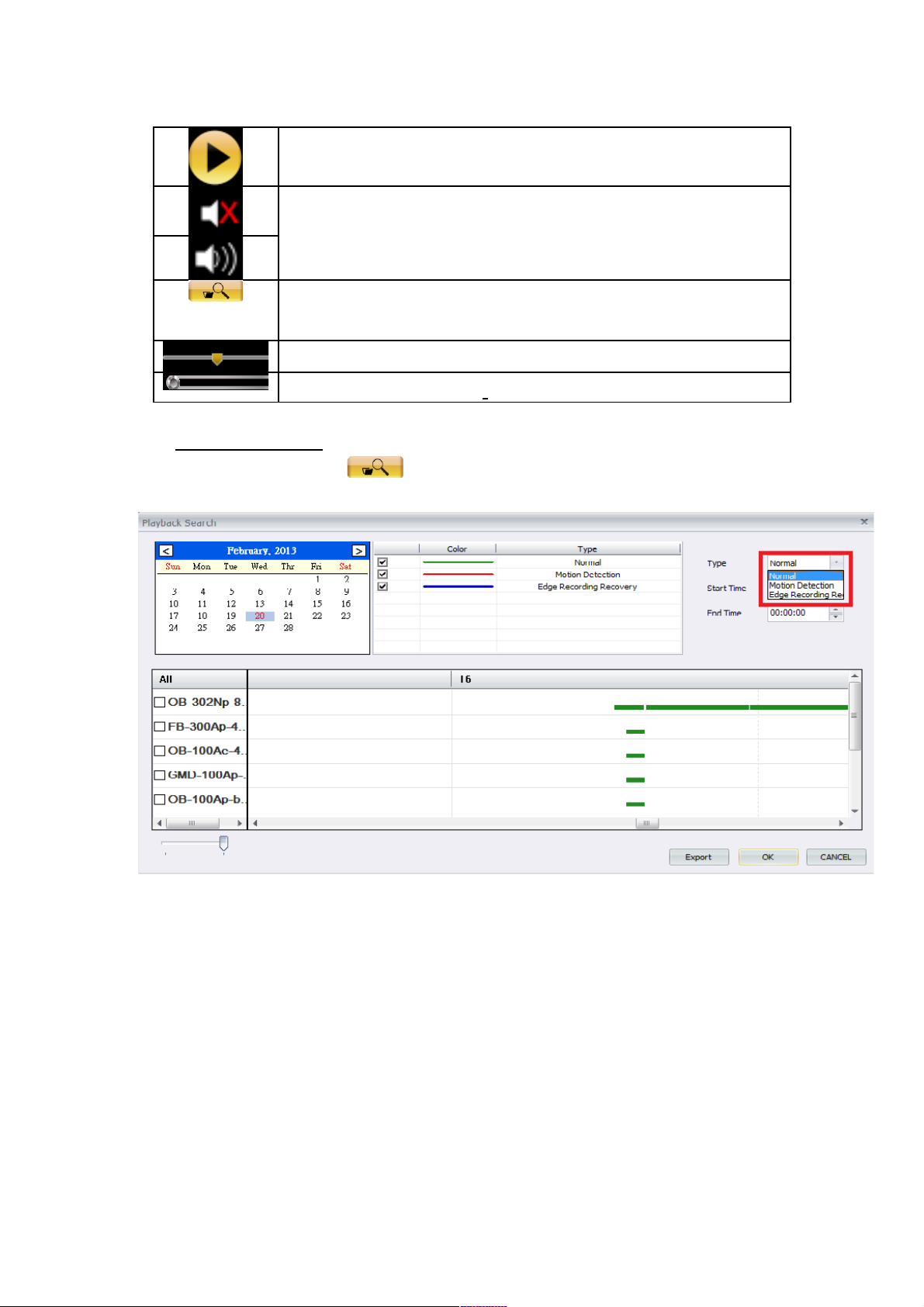
Search Image Files
Click <Search Image Files> button to search video clip by event types or date-time.
Please refer to the below steps:
1. Please select the record type to playback. Event types consist of normal
records, Motion detection, and offline records.
78 78
Page 79
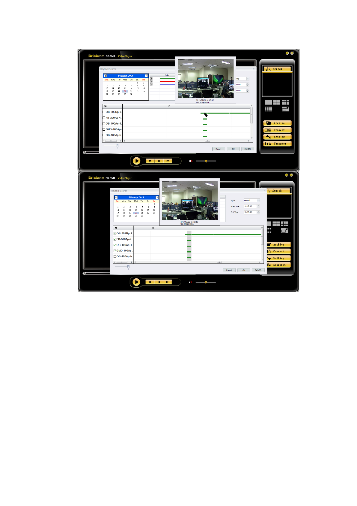
2. Please set time period to playback by circling horizontal bar or
inputting time period manually in the top right of the window. If
necessary, modify the range of timeline on the bottom left of the
window.
79 79
Page 80
3. Tick off the cameras in left side window. Click ‘OK’ to start
playback service.
NOTE 1
Please make sure to select the record types before starting playback
service. The offline record & motion record will not play if selecting
record type to be normal.
NOTE 2
In order to decrease system loading, it is recommended to configure
BRC64 with record only mode while operating 16 channel playback
simultaneously.
NOTE 3
The preview snapshot will pop-up if the mouse gets close to timeline
with available video clips.
80 80
Page 81
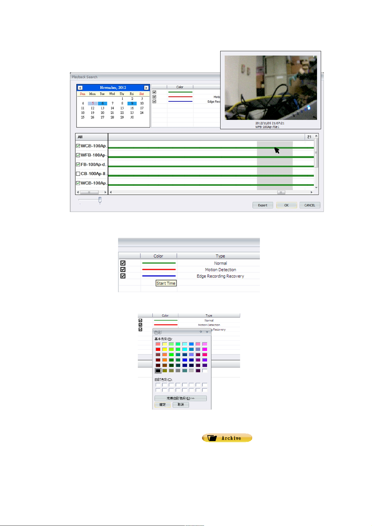
The user can also change the color of each category.
1. Move the mouse to <Color> bar on right below side of the window.
2. Double click to adjust the color setting.
Archive UI is available when selecting <Archive> button. The preview
snapshot pops up after choosing the recorded video. Double click the left mouse button
to start playback.
81 81
Page 82
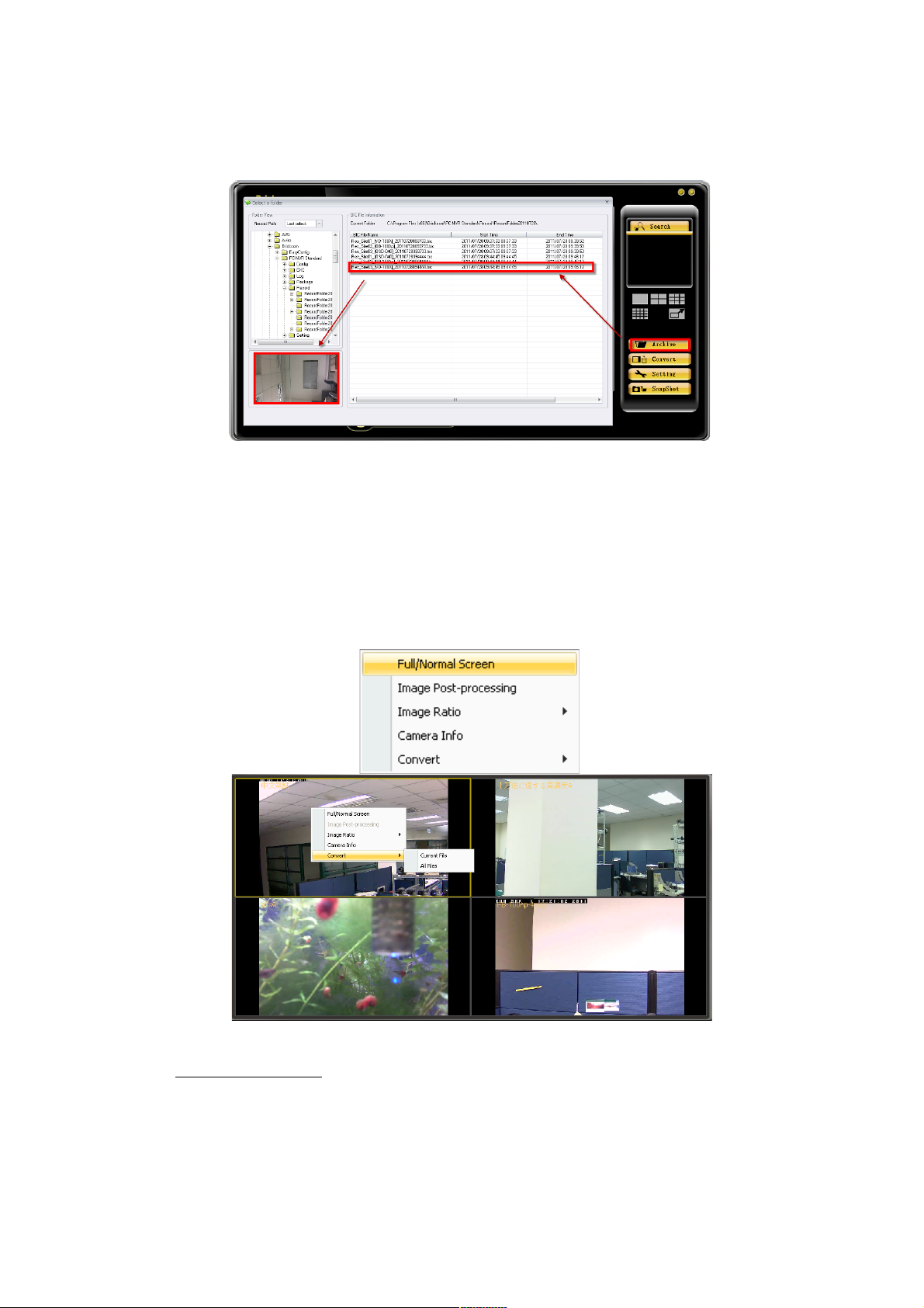
Click the right mouse button in the playback window to modify the following functions:
Full/Normal Screen.
Image Post-processing.
Image Ratio.
Camera Info.
Convert.
Full/Normal Screen
Full screen is shown below:
82 82
Page 83
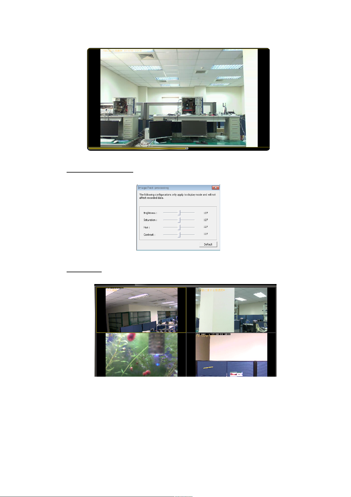
Image Post-processing
Click Image Post-processing to modify the image setting.
Image Ratio
Click Image Ratio to change the width-and-length ratio. There are two displays to select.
83 83
Page 84
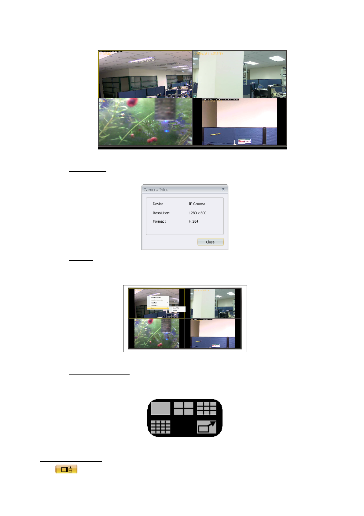
Camera Info
Check the information of the camera.
Convert
Convert the present / all video clips to be AVI format.
Modify Window Grid
The types of window grid are 1x1, 2x2, 3x3, 4x4, and full screen.
Convert Image File
The <Convert Image File> icon is used to convert recorded video files to WMV
84 84
Page 85
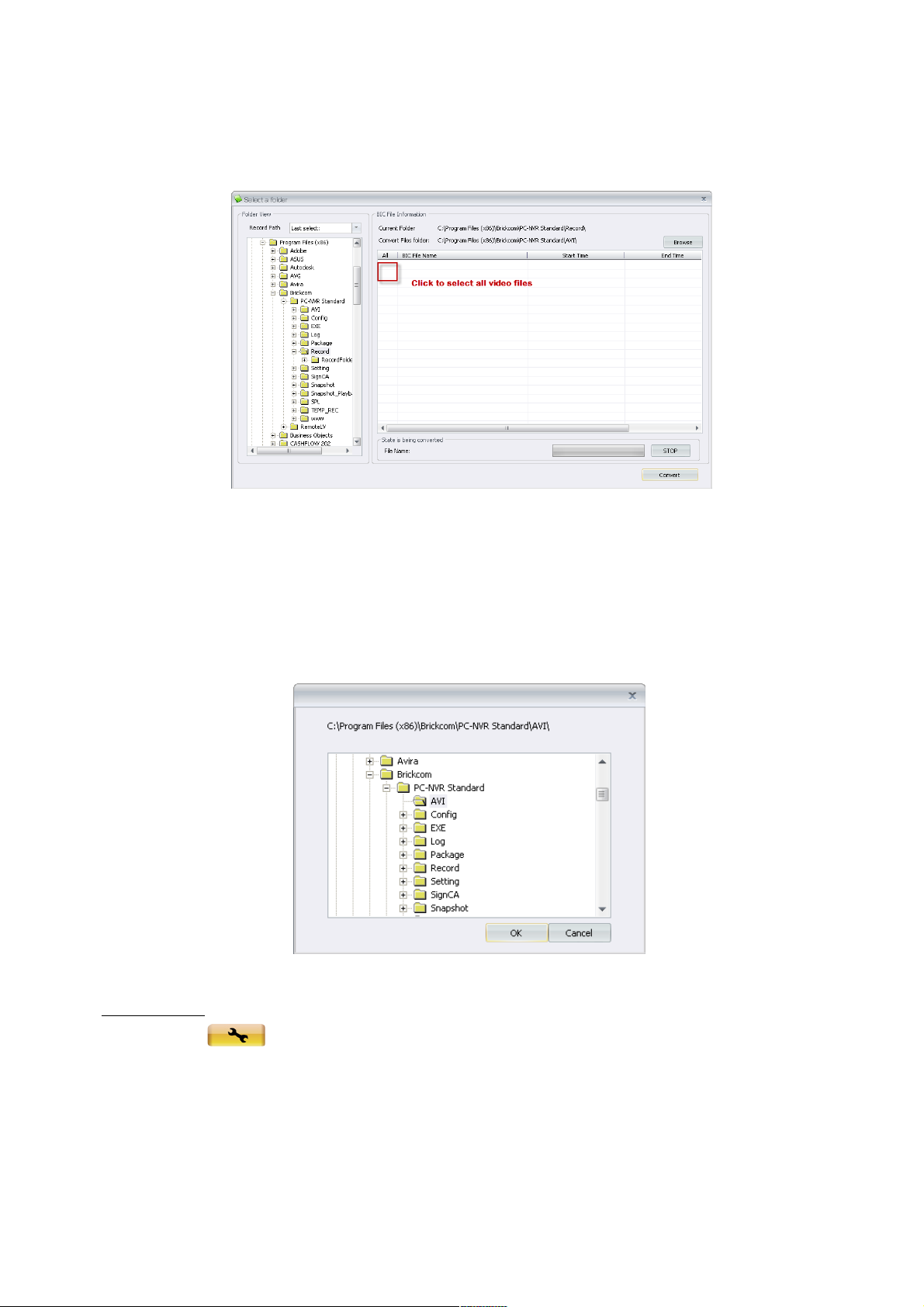
video format. Click the icon to open the video files and select the files to be converted.
Click <Convert> to start conversion of selected files.
There is a service to select all video clips by pressing ‘All’. If the user wishes to stop the
conversion, click <STOP> to abort. The converted files will be stored under folder
‘C:\Program Files\Brickcom\BRC64\AVI’. To choose an alternate destination folder, click
<Browse> and chose a desired folder.
View Setting
Click on the <View Setting> to choose to show or hide the time on the playback
video. Check <Show Time>, and the time will be shown on the screen. Uncheck to hide
the information.
File Path determines where AVI conversion and snapshot files are saved on the
computer HDD. Click on <Browse> to select desired folders. In addition, snapshot
pictures can be saved using Bmp and/or Jpg formats. After the settings are selected,
85 85
Page 86
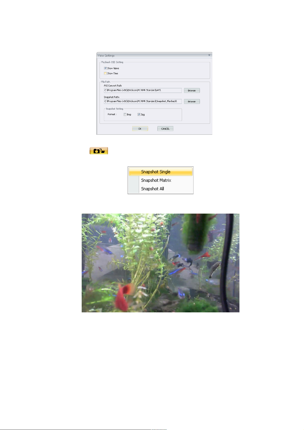
click <OK> to save.
Snapshot
Click <Snapshot> button to select. The files will be stored under folder
‘C:\Program Files\Brickcom\BRC64\Snapshot_Playback’.
Snapshot Single-Snapshot single image.
Snapshot Matrix-Snapshot all window grids image.
86 86
Page 87
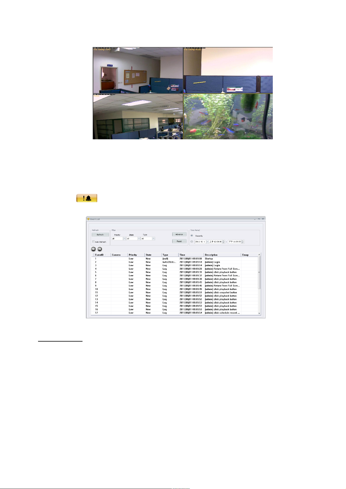
Snapshot All-Snapshot all video images individually.
Event
Click on the <Event> icon to list all log and event activities of the camera.
Camera Event
Click <Refresh> to refresh the list of events. The user can filter events two ways. The
first is to use the three settings: priority, state, and type. The second is to filter using the
‘Advanced’ settings. Click <Advanced> and the following menu will appear. The user
can then select the filters for viewing the event list and click <OK> when done.
87 87
Page 88
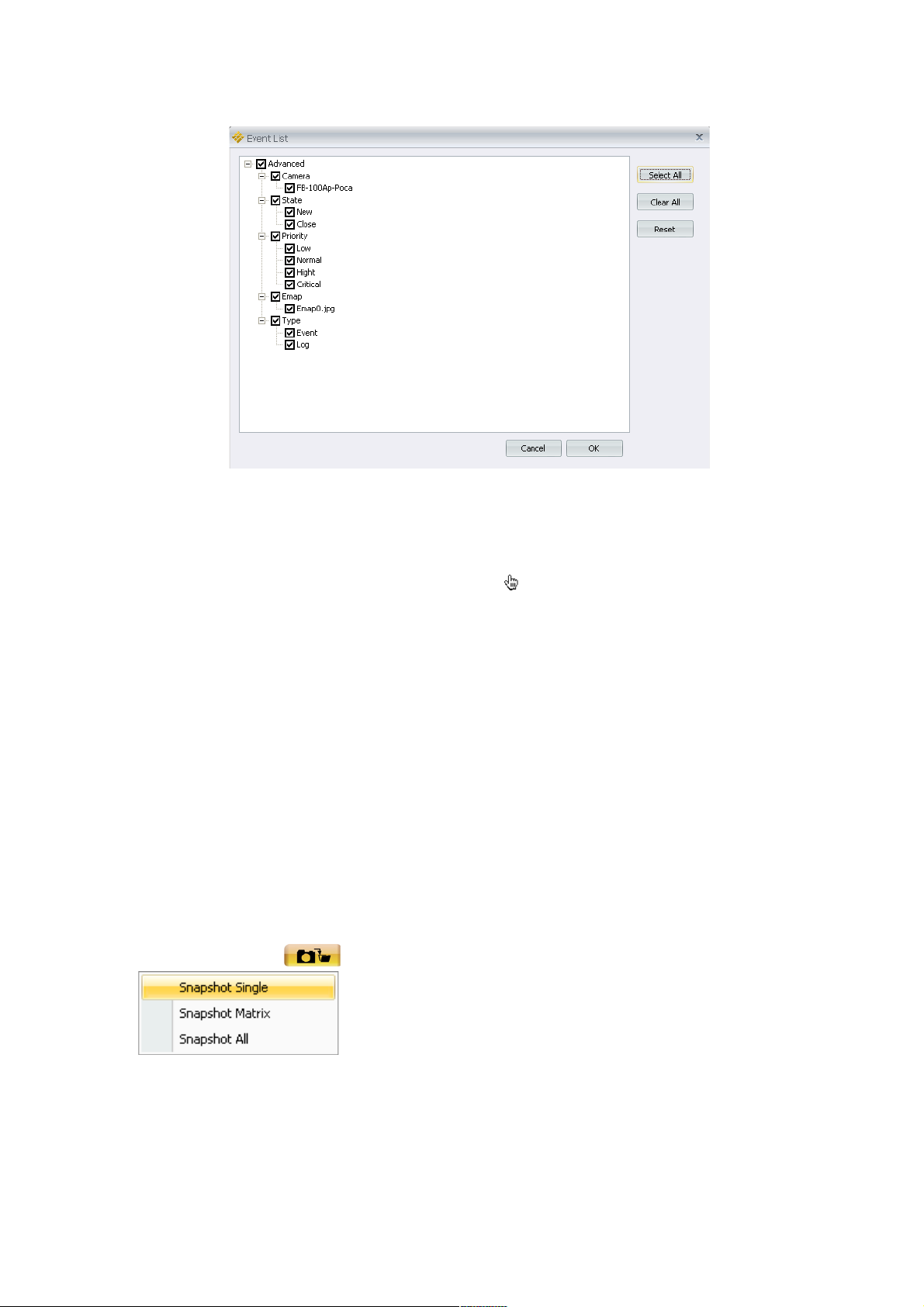
Under ‘Time Period,’ users can choose to view events from the most recently recorded or
a specific time period. The user can change the status of an event log by moving the
mouse pointer over the <State> column. When appears, click to change the status of
the log.
Snapshot
The Snapshot function is a simple screen capture tool. The screenshots are saved to the
default path ‘C:\Program Files\Brickcom\BRC64\Snapshot’ or an alternative file path
chosen by the user.
There are two ways to take a snapshot. The first is to click on the <Snapshot> icon. Click
<OK> to save the file. The second way is to right click on the window, and select
<Snapshot> to snapshot single. The file will be saved without displaying the image.
Click <Snapshot> button to select.
Snapshot Single-Snapshot single image
88 88
Page 89
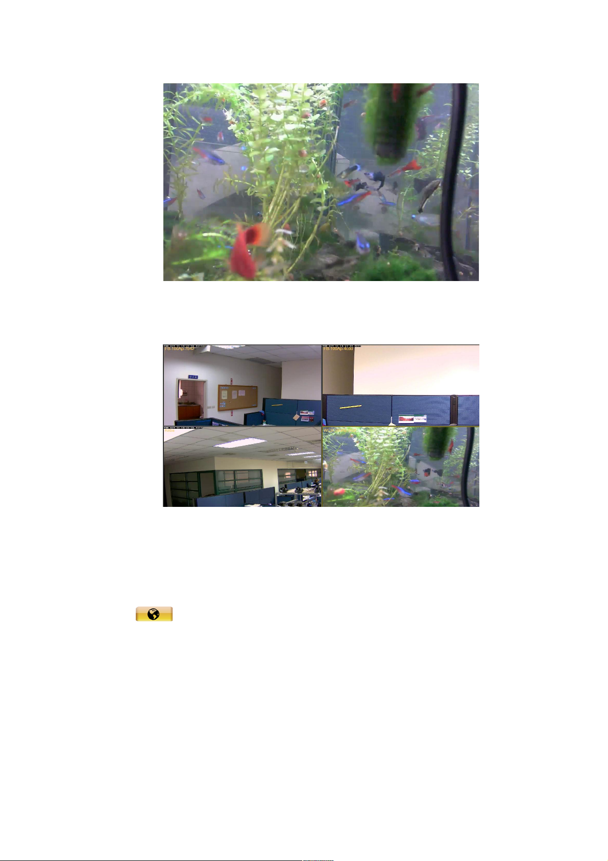
Snapshot Matrix-Snapshot all window grids image.
Snapshot All-Snapshot all video images individually.
E-Map
Click on the <E-map> icon to open the E-Map program. The E-Map is a program
that allows the user to illustrate the positions of the cameras on a self selected image. If
the BRC64 is being used to monitor multiple locations, the user can have multiple images
to display the location of the cameras.
89 89
Page 90
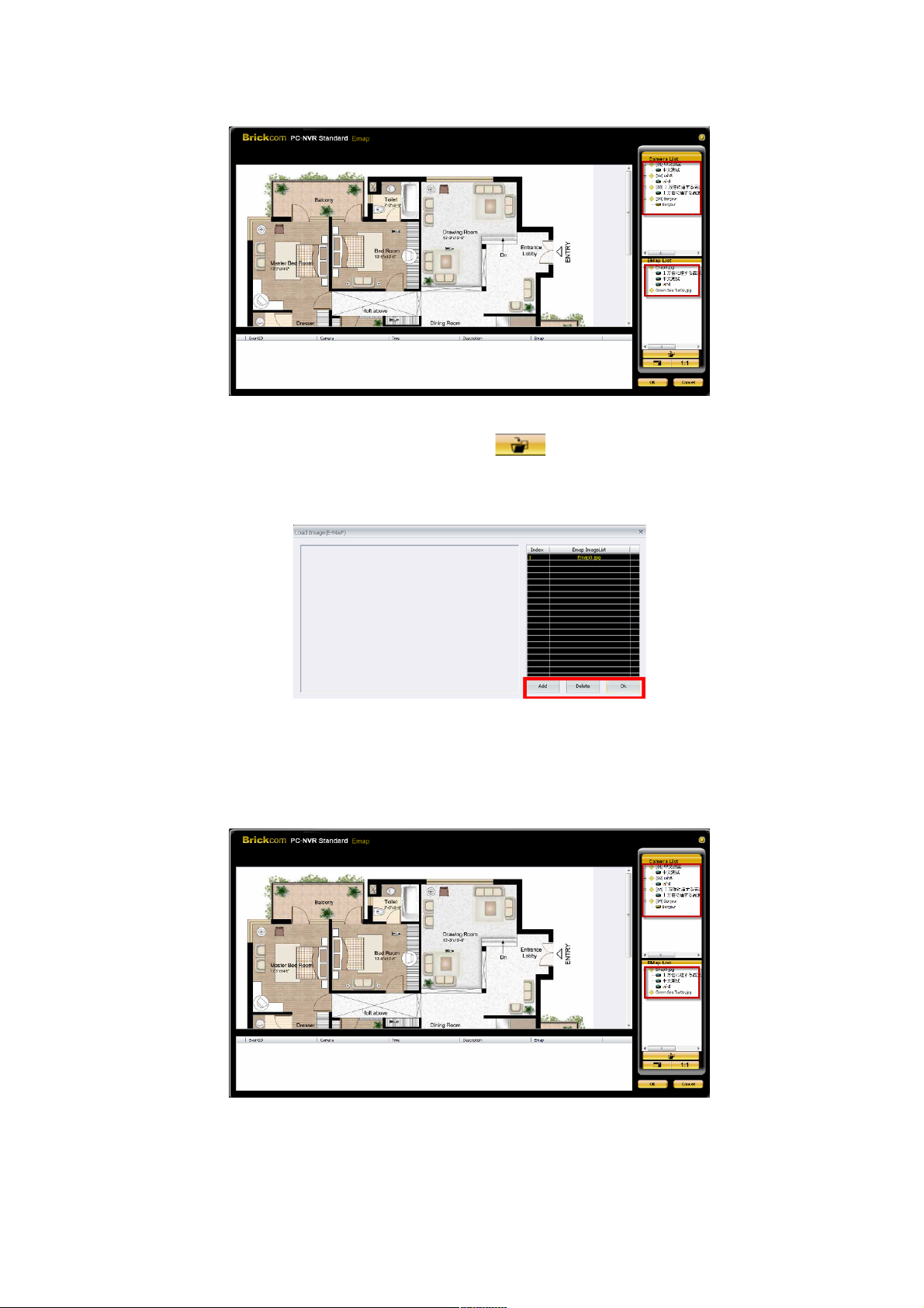
Add an image to the E-Map by selecting the <Load Image> button. The figure
below is the Load Image window to add or delete images. Click on < Add> to add an
image.
After the image is loaded, the filename of the image will be displayed on the list. ‘Index’
indicates the order (starting from ‘1’) of the files. Click <OK> to save the settings.
90 90
Page 91
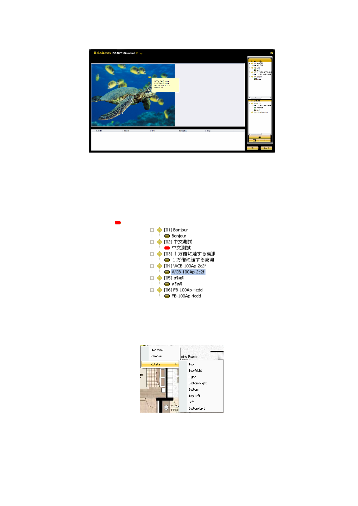
Add cameras to the E-Map by selecting <E-Map List> menu to list the map images. The
user can select an image and it will be displayed in the E-Map main window. Click
<Camera> on the control panel to list the site tree. Drag and drop a camera from the site
tree to any desired position on the main image. If camera is implementing motion detection,
the camera’s icon will be ,please refer to the below photo
The users can drag-and-drop cameras to access Live View, to remove the camera, or to
rotate its recording direction. The rotating directions include: Top, Top-Right, Right,
Bottom-Right, Bottom, Top-Left, Left, and Bottom-Left.
When the mouse pointer scrolls over a camera icon in the image, an information dialog
box will be displayed as below.
91 91
Page 92
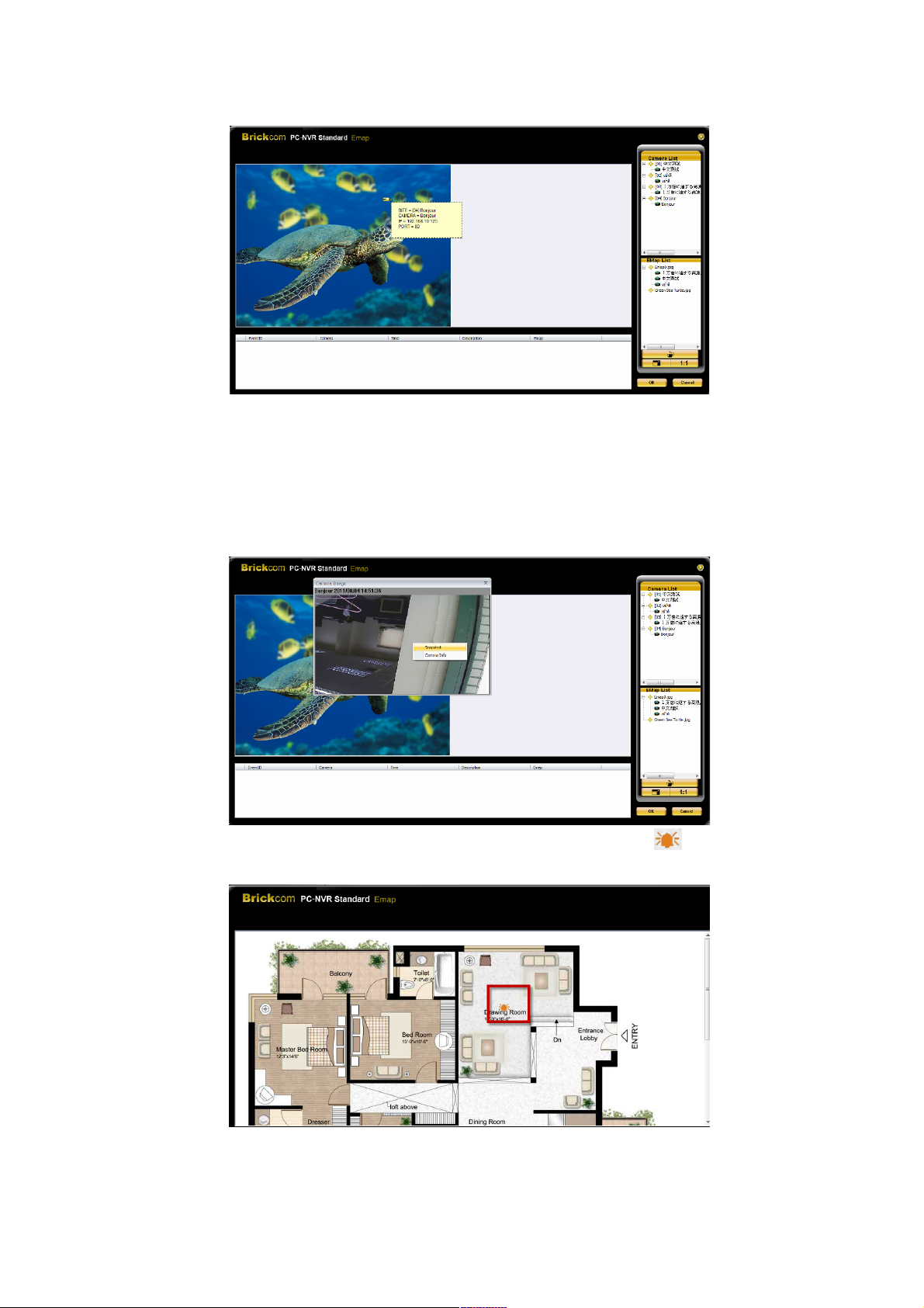
Double click on any camera icon in the image to display the live preview image of the
camera. Right click on the camera preview window to display the camera control menu.
The menu items includes: Snapshot, and Camera Info.
If the camera is implementing motion detection, the camera’s icon will be . Please refer to the
below photo.
ACCOUNT MANAGE
92 92
Page 93
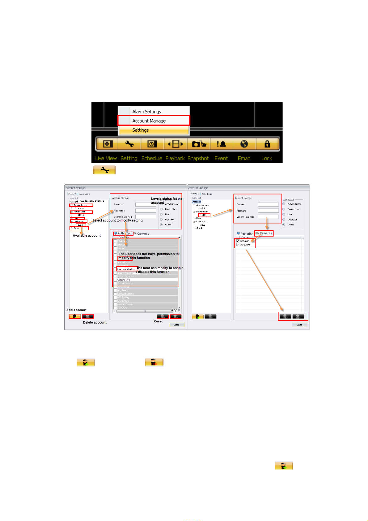
This function is able to manage user’s authority, including lower levels status and
individual account. Only administrators have the right to modify all accounts. There are
five levels of status in default setting: Administrator, Power User, User, Operator, and
Guest.
1. Click <Setting> Button and select <Account Manage>.
2. The following photo is the UI for account management. Each levels
status consist of different accounts. Users are able to add account
/delete account /manage lower levels status accounts.
User can modify username & password in <Account manage>.
<User Status> shows the levels status of the account. Each
function is able to open/close by ticking off the mouse. Functions
with gray are to indicate unable-to-modify. Select <Cameras> to
decide if the camera is able to be operated or not.
3. There are two ways to add accounts:
3.1 Select user status of new account, then set up username &
password. Finally modify permission for each function. Click
button to finish the setting.
93 93
Page 94
3.2 Select the <User List> to decide the level status of new account.
Then set up username & password. Finally modify permission for
each function. Click button to finish the setting.
4. Click button to apply the setting or return to default setting
by selecting button.
NOTE
If the user is unable to use NVS service, please contact higher levels
status account to enable this function.
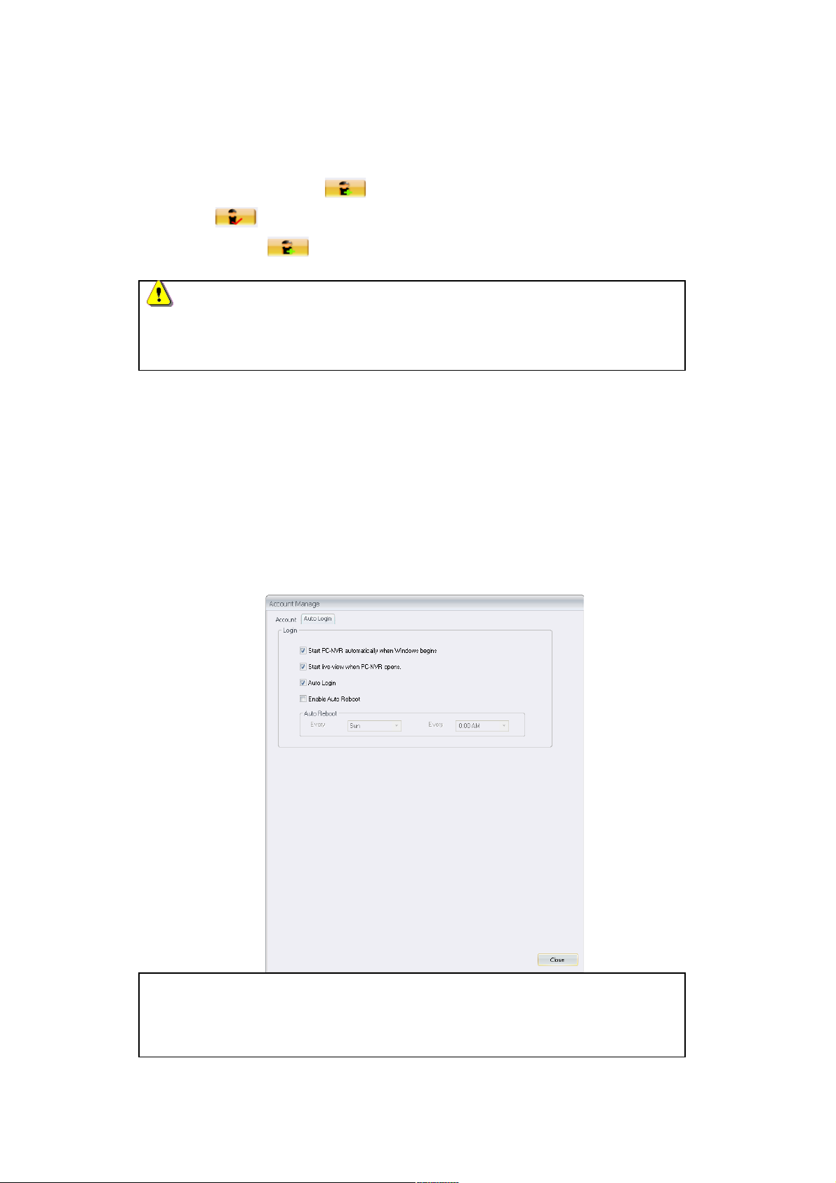
Auto Login
For the easy-to-use, BRC64 supports the following functions:
Start BRC64 automatically when Windows begins.
Start live-view when BRC64 opens.
Auto Login.
Set the Auto Reboot into Schedule.
Note
If your system device is Windows Vista or Windows 7, please close the UAC
function to avoid unnecessary errors. Please refer to the below steps:
94 94
Page 95
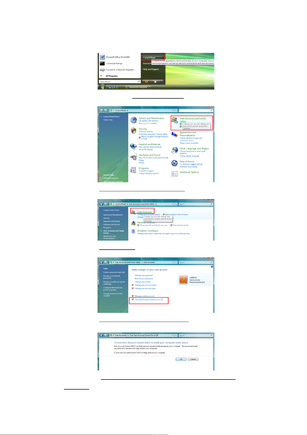
Vista
1. Please refer to the path as Start->Control Panel.
2. Please select User Accounts and Family Safety.
3. Please select User Account.
4. Please select Turn User Account Control in or off.
5. Please cancel Use User Account Control (UAC) to help protect your
computer.
95 95
Page 96
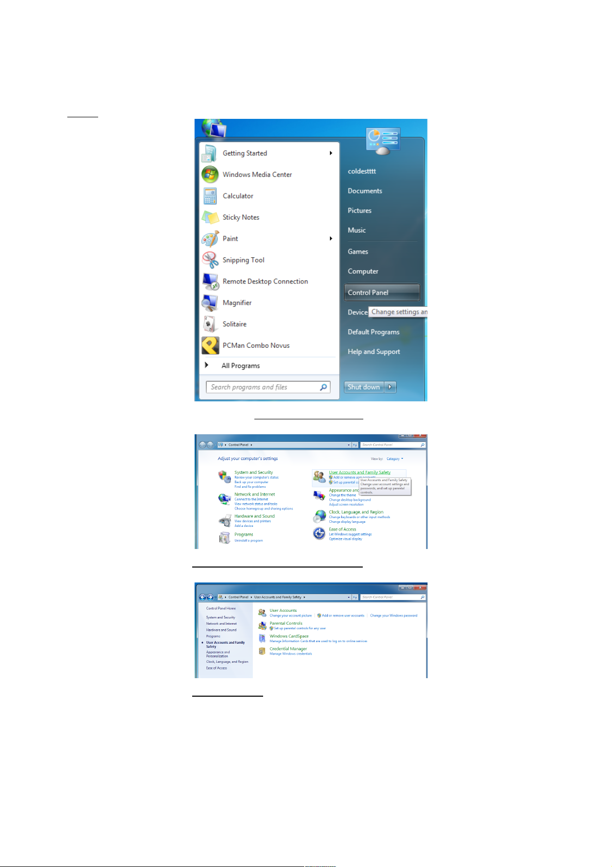
WIN7
1. Please refer to the path as Start->Control Panel.
2. Please select User Accounts and Family Safety.
3. Please select User Account.
96 96
Page 97
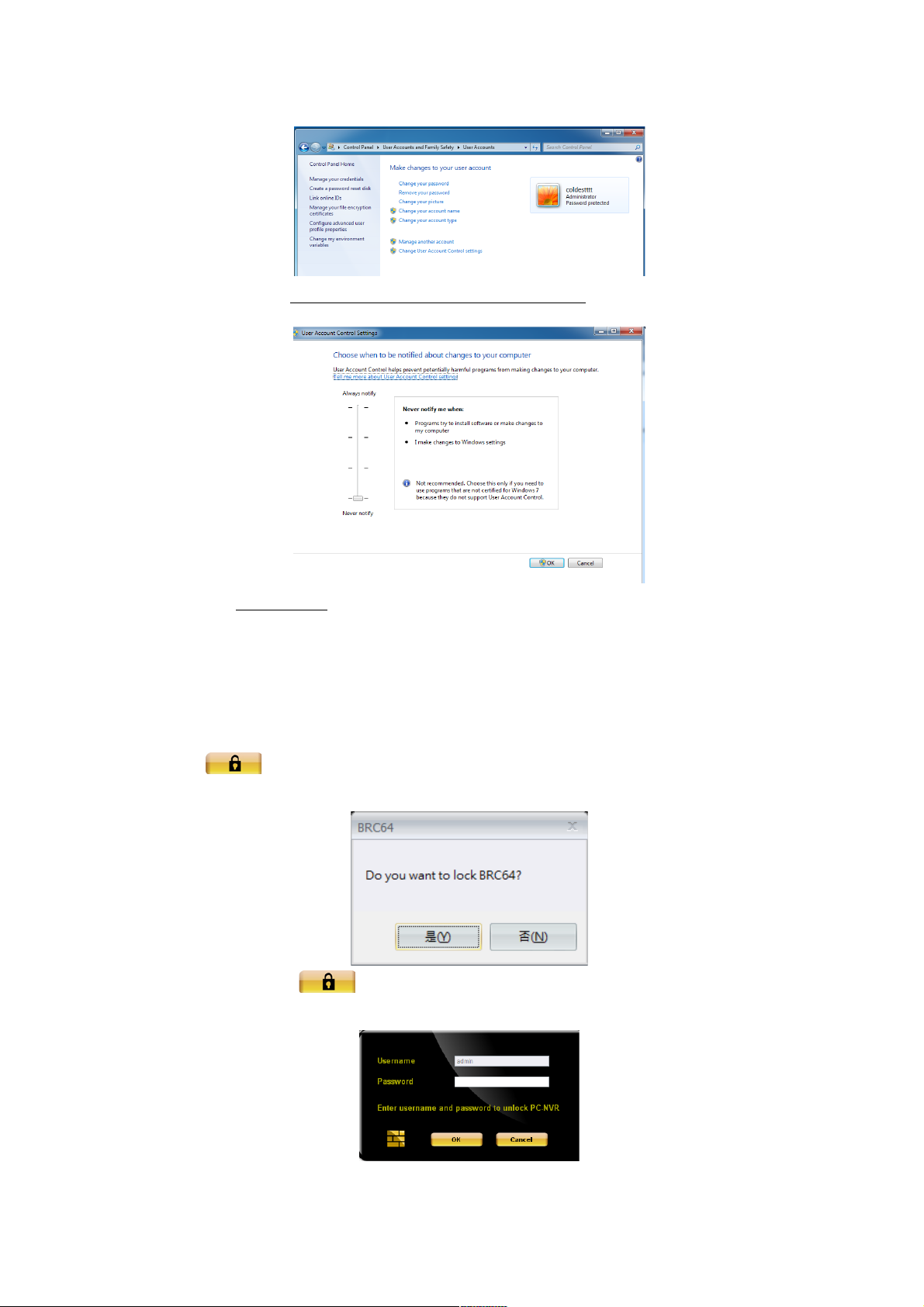
4. Please select Change User Account Control settings.
5. Select Never notify to finish the setting.
Lock
The Lock function can be used to lock the BRC64 and prevent unauthorized access
when the user needs to be away from the computer for any length of time.
Click on the <Lock> icon and a confirmation message will be displayed as below.
Click ‘Yes’ to confirm.
To unlock, click on the icon again. The user will need to enter the password to
unlock the BRC64 by the following window.
97 97
Page 98
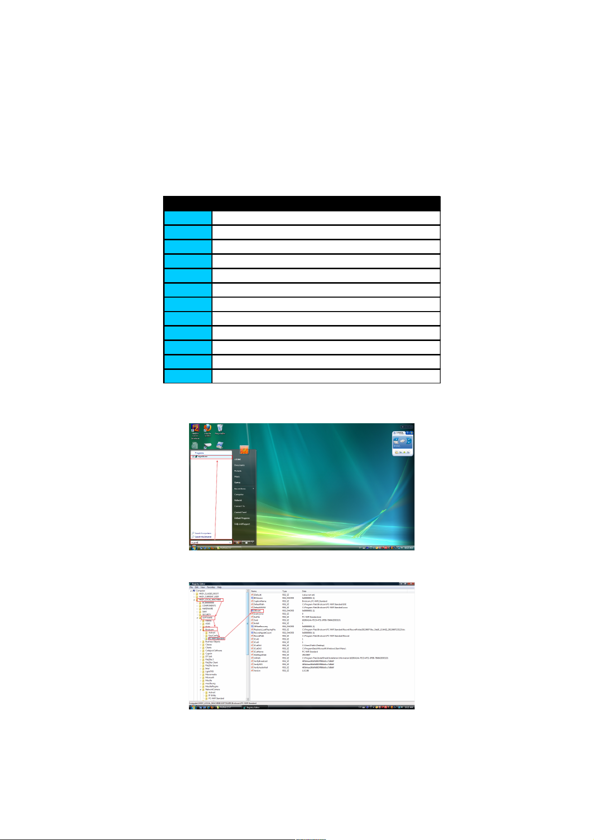
Hot-Key
In order to give more support and service for customers, BRC64 provides hot-keys to
start function immediately. Here is the list for hot-keys:
Hotkey Description
F2 Enable all Record
F3 Enable all MD Record
F4 Disable all Record
F5 Set selected camera DI Status to Low
F6 Set selected camera DI Status to High
F7 Set all cameras DI Status to Low
F8 Set all cameras DI Status to High
Ctrl+F5 Set selected camera DI detection disable
Ctrl+F6 Set selected camera DI detection enable
Ctrl+F7 Set all cameras DI detection disable
Ctrl+F8 Set all cameras DI detection enable
F9 Show DI Status in Video Frame(10 Sec)
How to start DI service:
1. Start search->‘regedit’.
2. Please enter to configure DI service via
HKEY_LOCAL_MACHINE\SOFTWARE\BRICKCOM\BRC64.
98 98
Page 99
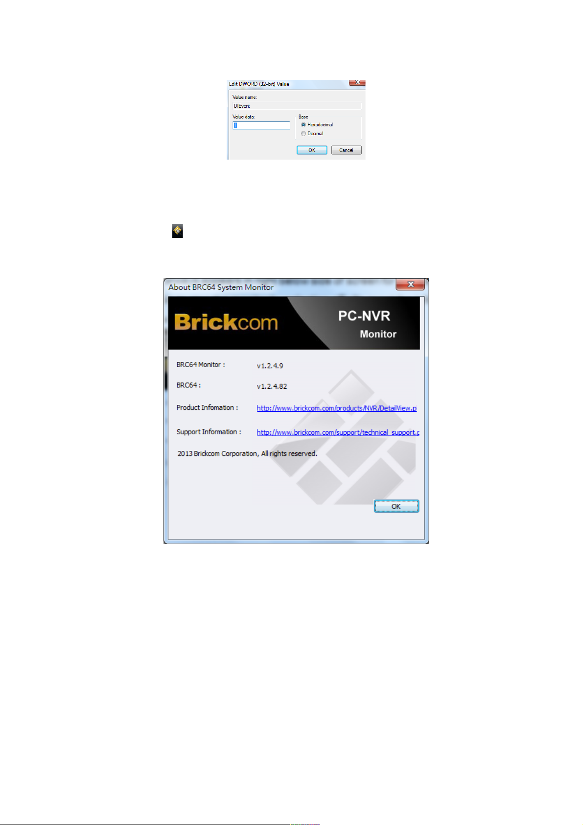
3. Please select DIEvent to change Value data from 0 to 1.
Watch dog
The icon of watch dog always appears in right below side of screen for the sake of monitoring
the BRC64’s. Users are able to stop the monitor by selecting <Exit> or get the information by
<About>. Please see the below photo.
99 99
 Loading...