

Bresser Weather Center WTW 5in1 Instruction Manual
Weather Station · Wetterstation ·
Weather Center WTW 5in1
EN Instruction manual
DE Bedienungsanleitung
DE
Besuchen Sie unsere Website über den folgenden QR Code oder Weblink um weitere Informationen
zu diesem Produkt oder die verfügbaren Übersetzungen dieser Anleitung zu finden.
EN
Visit our website via the following QR Code or web link to find further information on this product or
the available translations of these instructions.
FR
Si vous souhaitez obtenir plus d’informations concernant ce produit ou rechercher ce mode
d’emploi en d’autres langues, rendez-vous sur notre site Internet en utilisant le code QR ou le lien
correspondant.
NL
Bezoek onze internetpagina via de volgende QR-code of weblink, voor meer informatie over dit
product of de beschikbare vertalingen van deze gebruiksaanwijzing.
ES
¿Desearía recibir unas instrucciones de uso completas sobre este producto en un idioma determinado?
Entonces visite nuestra página web utilizando el siguiente enlace (código QR) para ver las versioneAs
disponibles.
IT
Desidera ricevere informazioni esaustive su questo prodotto in una lingua specifica? Venga a
visitare il nostro sito Web al seguente link (codice QR Code) per conoscere le versioni disponibili.
www.bresser.de/P7002585
www.bresser.de/warranty_terms
GARANTIE · WARRANTY · GARANTÍA · GARANZIA
APP DOWNLOAD: APP DOWNLOAD:
Weather Underground is a registered trademark of The Weather Channel, LLC. both in the United States and internationally. The Weather
Underground Logo is a trademark of Weather Underground, LLC. Find out more about Weather Underground at www.wunderground.com
Apple and the Apple logo are trademarks of Apple Inc., registered in the U.S. and other countries. App Store is a service mark of Apple Inc.,
registered in the U.S. and other countries. Google Play and the Google Play logo are trademarks of Google Inc.

English...................................................................................................................
4
Deutsch .................................................................................................................
15

4 / 28
1 Imprint
Bresser GmbH
Gutenbergstr. 2
46414 Rhede
Germany
http://www.bresser.de
If you wish to submit a warranty claim or service request, please refer to the “Warranty” and “Service”
information in this document. Please be aware that any requests or submissions sent directly to the
manufacturer cannot be processed.
Errors excepted. Subject to technical modifications.
© 2019 Bresser GmbH
All rights reserved.
Reproduction of this document, including extracts, in any form (photocopied, printed etc.) or the use
and distribution of this document by electronic means (image file, website etc.) is not permitted without
the prior written consent of the manufacturer.
The terms and brand names of the respective companies used in this document are protected by
brand, patent or product law in Germany, the European Union and/or other countries.
2 Validity information
This documentation is valid for the products with the article numbers listed below:
7002585
Manual version: v0619
Manual description:
Manual_7002585_Weather-Center-WTW-5in1_en-de_BRESSER_v062019a
With any service inquiries, please state these information.
3 Features
• Measurement of Rainfall
• Measurement of wind speed
• Measurement of wind direction
• Internet time synchronization via PC
• Alarm with snooze function
• Outdoor temperature alarm (frost warning)
• Outdoor temperature (in °C or °F)
• Indoor temperature (in °C or °F)
• Humidity indoor/outdoor
• Barometric pressure
• Since function to display the total rainfall from a customized point in time.
• Highest and lowest value display
• Maximum/Minimum value memory
• Colour display
• Backlight
5 / 28
4 About this Instruction Manual
NOTICE
These operating instructions are to be considered a component of the device.
Please read the safety instructions and the operating instructions carefully before use.
Keep these instructions for renewed use at a later date. When the device is sold or given to someone
else, the instruction manual must be provided to the new owner/user of the product.
5 Parts overview Base station
1
2
8
16
1510
18
13
12 1411
25
A
B
C
3
4
6
5
7
17
19
22
20
9
24
23
18
21
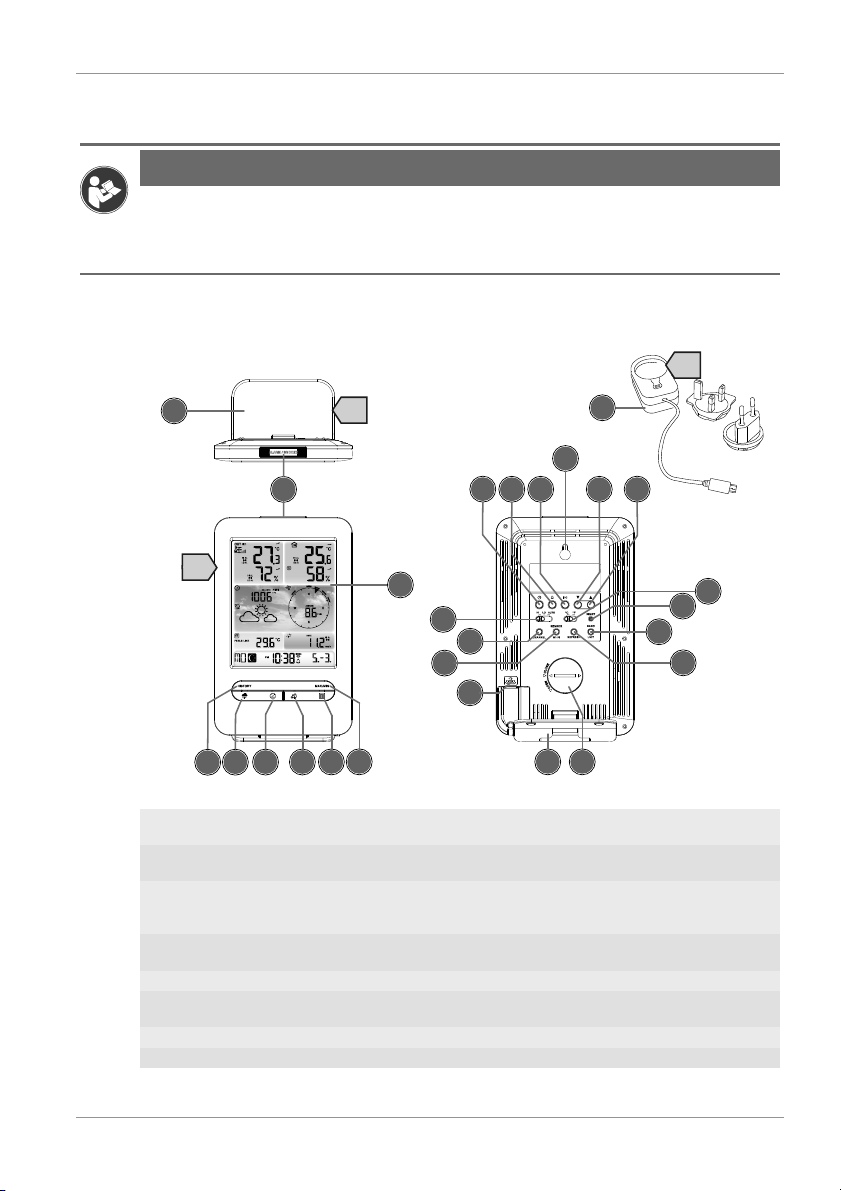
Illustration1: All parts of the base station
1 ALARM/SNOOZE button (snooze function
or interrupt alarm)
2 Colour display
3 RAIN button (display of various precipita-
tion values)
4 BARO button (display of different atmo-
spheric pressure values)
5 INDEX button (display change between
'feels like' temperature, dew point, heat index and wind chill index)
6 WIND button (display change between av-
erage and current gust)
7 MAX/MIN button (switch between highest,
lowest or current value display)
8 HISTORY button (retrieve measurements
for the past 24 hours)
9 CHANNEL button (channel selection) 10 CLOCK SET button (manual time setting)
11 ALARM button (Alarm setting) 12 ALERT button (e.g. set temperature
alarm)
13 Wall mount 14 DOWN button (value setting downwards)
15 UP button (value setting upwards) 16 RESET button (reset all settings)
6 / 28
17 HI/LO/AUTO slider (turn on/off back-
ground lighting)
18 Stand, removable
19 REFRESH button (refreshing data manu-
ally)
20 SENSOR / WI-FI button (start manual
sensor search or activate / deactivate WIFI)
21 Battery compartment (cover) 22 BARO UNIT button (change of atmo-
spheric pressure measurement unit)
23 °C/°F slider (display change betw. °C and
°F)
24 USB socket (power supply)
25 USB power adapter
6 Parts overview Multisensor
1
3
4
5
6
9
8
7
13
10
11
E
D
F
G
7
8
12
2
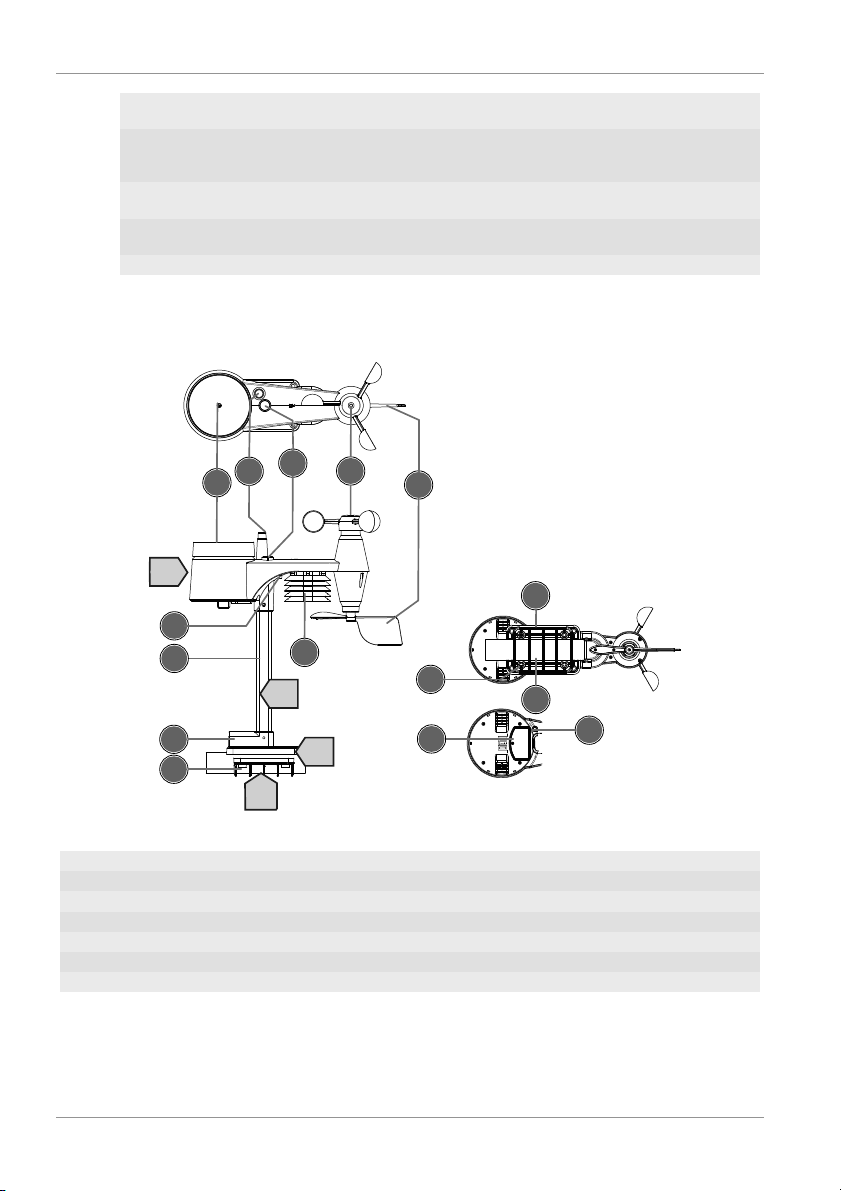
Illustration2: All parts of the multisensor
1 Rain gauge 2 Antenna
3 Circular level 4 Wind cups (wind speed)
5 wind vane (wind direction) 6 Thermo-Hygrometer
7 Pipe clamp 8 Mounting shoe
9 Mounting bar 10 Battery compartment (cover)
11 RESET button 12 LED function indicator
13 Mounting screws with nuts
7 / 28
7 Scope of delivery
Base station (A), USB power adapter (B) with 2 adapter attachments (EU and UK), stand (C), multifunctional outdoor sensor (D), mounting rod (E), mounting shoe (F), tube clamp (G), screws, instruction manual
Also required (not included):3 pcs. of 1.5V AA type batteries (outdoor sensor), 1 pc. of 3V CR2032
battery (base station)
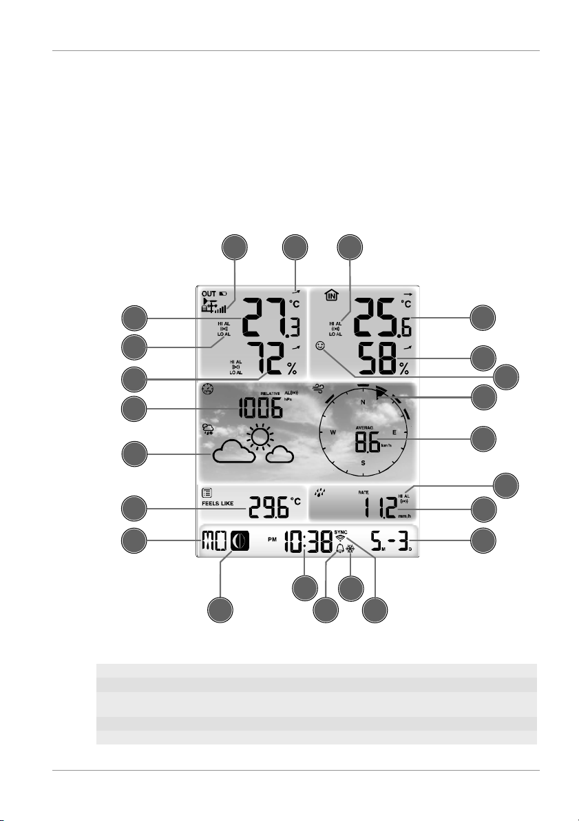
8 Screen display
23
2
1
9
10
15
14
18
7
4
21
20
8
22
3
5
6
13
11
12
17
16
19
Illustration3: Screen display
1 Wind speed 2 Wind direction
3 Signal strength for outdoor sensor 4 Outdoor temperature
5 Outdoor temperature alarm enabled (HI/
LO)
6 Outdoor humidity
7 Barometric pressure 8 Precipitation alarm enabled (HI/LO)
9 Precipitation amount 10 Date
8 / 28
11 WIFI synchronization 12 Ice alert enabled
13 Wake-up alarm enabled 14 Current time
15 Temperature felt 16 Moon phase
17 Weekday 18 Graphical weather trend display
19 Indoor humidity 20 Comfort indicator (climate)
21 Indoor temperature alarm enabled 22 Indoor temperature
23 Trend arrow (rising, constant or falling)
9 Before starting operation
NOTICE
Avoid connectivity disruptions!
To avoid connectivity disruptions between the devices, consider the following points before starting
operation.
1. Place base station (receiver) and remote sensor (sender) together as close as possible.
2. Set up power supply for the base station and wait until the indoor temperature is displayed.
3. Set up power supply for the remote sensor.
4. Position the base station and the remote sensor within the effective transmission range.
5. Ensure that the base station and remote sensor are assigned to the same channel.
When changing batteries always change batteries in the main unit as well as all remote units and re-
place them in the correct order, so the remote connection can be re-established. If either of the
devices is mains-powered, the power supply must be disconnected for a short moment also for this
device when exchanging the batteries. If batteries are exchanged in only one of the devices (i.e. the
remote sensor) the signal can’t be received or can’t be received correctly.
Note, that the effective range is vastly affected by building materials and position of the main and remote units. Due to external influences (various RC devices and other sources of interference), the
maximum distance can be greatly reduced. In such cases we suggest to position the main unit and the
remote sensor at other places. Sometimes all it takes is a relocation of one of these components of a
few inches!
10 First Steps
Follow the bullet points in order, to ensure a successful setup.
• Setting up power supply (base station and wireless sensor)
• Mount the remote sensor
• The base station is now in AP mode (LED flashes green) and ready for initial setup.
• Create a Weather Underground account and add the station to your account ("My Profile" / "Add
Weather station"). Here you will receive a station ID and a password, which will be needed in the next
step.
• Setting up the base station (Estabish Wi-Fi / Router connection)
• Viewing weather data via web, mobile or tablet
11 Setting up power supply
Base unit
1. Push the appropriate plug adapter attachment onto the spigot on the mounting plate of the USB
power adapter until it snaps into place.
2. Plug the MicroUSB plug into the USB connection socket on the base unit.
9 / 28
3. Insert the mains plug into the power outlet.
4. The device is energized directly.
Installing the backup battery:
1. Remove the battery compatment cover.
2. Insert the battery into the battery compartment. Make sure that the battery polarity (+/-) is correct .
3. Replace the battery compartment cover.
Remote sensor
5. Loosen the screw at the battery compartment cover with a small Philips screwdriver and remove
the cover.
6. Insert the batteries into the battery compartment. Ensure that the battery polarity (+/-) is correct.
7. Replace the cover and retighten it with the screw.
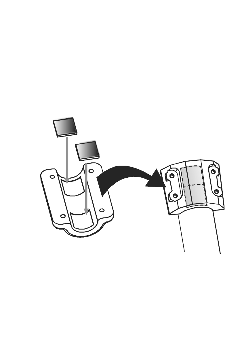
12 Attaching rubber pads
Attach the supplied self-adhesive rubber pads to the clamps as shown to ensure a firmer fitting of the
mounting rod.
13 Assembling and installing the multifunctional
remote sensor
Depending on the desired location, the remote sensor can be installed in two different ways.
NOTICE!During the assembly make sure that the upper part of the wind vanve is minimum 1.5
meters off the ground. Use the circular level in the sensor head to ensure a level installation. The
windmill must point to the North.
 Loading...