

Page 1
Digital RC alarm clock ·
Meteo TP Colour
EN Instruction manual
Page 2
DE
Besuchen Sie unsere Website über den folgenden QR Code oder Weblink um weitere Informationen
zu diesem Produkt oder die verfügbaren Übersetzungen dieser Anleitung zu finden.
EN
Visit our website via the following QR Code or web link to find further information on this product or the
available translations of these instructions.
FR
Si vous souhaitez obtenir plus d’informations concernant ce produit ou rechercher ce mode d’emploi en
d’autres langues, rendez-vous sur notre site Internet en utilisant le code QR ou le lien correspondant.
NL
Bezoek onze internetpagina via de volgende QR-code of weblink, voor meer informatie over dit product
of de beschikbare vertalingen van deze gebruiksaanwijzing.
ES
¿Desearía recibir unas instrucciones de uso completas sobre este producto en un idioma determinado?
Entonces visite nuestra página web utilizando el siguiente enlace (código QR) para ver las versiones
disponibles.
IT
Desidera ricevere informazioni esaustive su questo prodotto in una lingua specifica? Venga a visitare il
nostro sito Web al seguente link (codice QR Code) per conoscere le versioni disponibili.
www.bresser.de/P7007910000000
www.bresser.de/warranty_terms
GARANTIE · WARRANTy · GARANTíA · GARANzIA
Page 3

iii
Contents
1 Imprint .............................................................................................................................................................4
3 Features...........................................................................................................................................................4
4 About this Instruction Manual.......................................................................................................................5
5 Parts overview and scope of delivery ..........................................................................................................6
6 Screen display ................................................................................................................................................7
7 Before starting operation...............................................................................................................................8
8 Setting up power supply................................................................................................................................8
9 Automatic time setting...................................................................................................................................9
10 Manual time setting ........................................................................................................................................9
11 Alarm setting................................................................................................................................................... 9
12 Snooze function............................................................................................................................................ 10
13 Temperature alarm setting ..........................................................................................................................10
14 Receiving measurements automatically ....................................................................................................10
15 Trend arrow indicators................................................................................................................................. 11
16 Ice pre-alert ...................................................................................................................................................11
17 Temperature display ....................................................................................................................................11
18 MAX/MIN temperature values ......................................................................................................................11
19 Projection onto walls or ceilings ................................................................................................................11
20 EC Declaration of Conformity .....................................................................................................................12
21 Disposal......................................................................................................................................................... 12
22 Warranty ........................................................................................................................................................12
Page 4

4 / 16
1 Imprint
Bresser GmbH
Gutenbergstr. 2
46414 Rhede
Germany
http://www.bresser.de
If you wish to submit a warranty claim or service request, please refer to the “Warranty” and “Service”
information in this document. Please be aware that any requests or submissions sent directly to the
manufacturer cannot be processed.
Errors excepted. Subject to technical modifications.
© 2018 Bresser GmbH
All rights reserved.
Reproduction of this document, including extracts, in any form (photocopied, printed etc.) or the use
and distribution of this document by electronic means (image file, website etc.) is not permitted without
the prior written consent of the manufacturer.
The terms and brand names of the respective companies used in this document are protected by
brand, patent or product law in Germany, the European Union and/or other countries.
2 Validation
This document is valid for the products with the following part numbers:
7007910000000
Version of manual: v022018a
Name of manual: Manual_7007910000000_Meteo-TP-Colour_en_BRESSER_v022018a
Information is always provided for service requests.
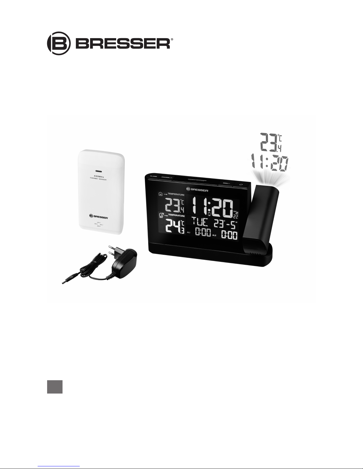
3 Features
• Elegant design and color display
• Display of time, date, weekday, alarm
• Indication of indoor / outdoor temperature
• Min./Max. value memory of the indoor / outdoor temperature
• Weekday display can be set in 7 languages
• Projection of information onto walls or ceilings
• Time information via DCF radio transmission
• Red LED projection with adjustable focus
• LED backlight (adjustable in 3 steps: light / low / auto-dimmer)
• Automatic time adjustment
• Dual alarm clock with snooze function
• Incl. external sensor and power supply
Page 5

5 / 16
4 About this Instruction Manual
NOTICE
These operating instructions are to be considered a component of the device.
Please read the safety instructions and the operating instructions carefully before use.
Keep these instructions for renewed use at a later date. When the device is sold or given to someone
else, the instruction manual must be provided to the new owner/user of the product.
Page 6

6 / 16
5 Parts overview and scope of delivery
1
2
3
4
5
6
8
10
9
7
11
19
23
22
10
9
25
24
12
21
13
18
20
14
15
16
17
29
31
28
26
27
A
B
C
30
Illustration1: Parts overview for base station (top) and remote sensor (bottom)
1 ALARM button (Alarm setting) 2 +/CHANNEL button (channel selection or
value change upwards)
3 ALARM/SNOOZE button (snooze function) 4 -/MEM button (retrieve saved values or value
change downwards)
5 REVERSE button (image rotation of the pro-
jection)
6 Projector lens
7 Projector arm 8 Focussing wheel
9 ALARM ON/OFF switch (AL 2) (activate or dis-
able alarm 2)
10 ALARM ON/OFF switch (AL 1) (activate or dis-
able alarm 1)
Page 7

7 / 16
11 Display 12 YEAR button (display change between year
and date)
13 TIME SET button (manual time/date setting
and user defined settings)
14 ALERT button (set temperature alarm)
15 SENSOR button (initialize remote sensor data
reception)
16 12/24 button (display change between 12 and
24 hours mode)
17 °C/°F button (display change between °C or
°F)
18 RESET button (reset all settings)
19 DC connection socket for coaxial/barrel con-
nector
20 HI/LO/AUTO switch (display brightness)
21 PROJECTION ON/OFF switch (activate or dis-
able projection)
22 Battery compartment cover (base device)
23 Battery compartment (base device) 24 DC coaxial/barrel connector
25 DC power adapter with EU mains plug. 26 Function indicator
27 Wall mount 28 Battery compartment cover (Remote sensor)
29 Battery compartment (Remote sensor) 30 RESET button (reset all settings)
31 RCC button (initialize time signal reception)
Scope of delivery
Base station (A), remote sensor (B), power adapter (C)
Also recommended (not included):
2 pcs. Mignon batteries (1.5V, AA type); 3 pcs. Micro batteries (1.5V, AAA type)
6 Screen display
1
2
6
5 8
4
3
10
9
11
13
12
14
15
17
16
17
18
14
15
7
19
20
21
23
22
20
24
25
Illustration2: Screen display for the base station
Page 8

8 / 16
1 Symbol indoor area 2 Temperature trend (indoor) (rising, steady or
falling)
3 Alarm symbol for defined low temperature (in-
door)
4 Alarm symbol for defined high temperature (in-
door)
5 AM/PM information in 12-hour time mode 6 Current time (hours)
7 Battery level indicator (base device) 8 Current time (minutes)
9 Daylight saving time (DST) 10 Symbol for radio signal
11 Current time (seconds) 12 Day (D)
13 Month (M) 14 Alarm time (minutes)
15 Alarm time (hours) 16 Alarm symbol (bell)
17 Symbol for alarm time 2 18 Weekday
19 Temperature value (outdoor) 20 Symbol for highest (MAX) or lowest (MIN)
value
21 Ice warning 22 Battery level indicator (remote sensor)
23 Symbol outdoor area with channel display 24 Temperature value (indoor)
25 Temperature unit (°C or °F selectable)
7 Before starting operation
NOTICE
Avoid connectivity disruptions!
To avoid connectivity disruptions between the devices, consider the following points before starting
operation.
1. Place base station (receiver) and remote sensor (sender) together as close as possible.
2. Set up power supply for the base station and wait until the indoor temperature is displayed.
3. Set up power supply for the remote sensor.
4. Position the base station and the remote sensor within the effective transmission range.
5. Ensure that the base station and remote sensor are assigned to the same channel.
When changing batteries always change batteries in the main unit as well as all remote units and replace them in the correct order, so the remote connection can be re-established. If either of the
devices is mains-powered, the power supply must be disconnected for a short moment also for this
device when exchanging the batteries. If batteries are exchanged in only one of the devices (i.e. the
remote sensor) the signal can’t be received or can’t be received correctly.
Note, that the effective range is vastly affected by building materials and position of the main and remote units. Due to external influences (various RC devices and other sources of interference), the
maximum distance can be greatly reduced. In such cases we suggest to position the main unit and the
remote sensor at other places. Sometimes all it takes is a relocation of one of these components of a
few inches! Though the remote unit is weather proof, it should be placed away from direct sunlight,
rain or snow.
8 Setting up power supply
Base device
1. Insert the DC connector into the connection socket of the base station.
2. Insert the mains plug into the power outlet.
3. The device is energized directly.
4. Wait until the indoor temperature is displayed on the base station.
Page 9

9 / 16
NOTICE!For permanent operation, mains power supply is recommended. Alternatively a
power supply with batteries is also possible, to keep the time setting in case of power failure. Proceed as follows:
5. Remove the battery compartment cover.
6. Insert the batteries into the battery compartment. Ensure that the battery polarity (+/-) is correct.
7. Replace the battery compartment cover.
8. Wait until the indoor temperature is displayed on the base station.
NOTICE!When switching from mains power supply to battery power supply or vice versa,
the power supply is being disabled for a short moment for technical reasons. Exception: permanent battery operation.
Remote sensor
1. Remove the battery compartment cover.
2. Insert the batteries into the battery compartment. Ensure that the battery polarity (+/-) is correct.
3. Set the channel selector switch to the desired channel.
NOTICE!This weather station can be operated with one or more remote sensors. Each remote sensor being connected must be operated on a different channel. If only one remote
sensor is connected, it should be operated on channel 1.
4. Replace the battery compartment cover.
9 Automatic time setting
After the power supply was established, the clock will automatically search for the radio signal. The
clock will automatically search for the radio signal.
If the radio signal is received correctly, the date and time will be set automatically and the radio control
signal icon turns on.
If the clock fails to receive the time signal, go ahead with the following steps:
1. Press RCC button at the remote sensor for approx. 2 seconds to initialize the radio signal reception again.
2. If the device is still not receiving the signal, the time must be set manually.
Read the detailed manual for more information about manual time and alarm setting (see download information on page 2).
10 Manual time setting
1. Press and hold TIME SET button for approx. 3 seconds to change to time setting mode.
2. Digits to be set are flashing.
3. Press +/CHANNEL or -/MEM button to change the value.
4. Press TIME SET button to confirm and continue to the next setting.
5. Settings order: 12/24 hour mode > Hours > Minutes > Seconds > Year > Change day and month >
Month > Day > Time zone > Language > Time signal reception ON/OFF > Daylight saving time
(DST) AUTO/OFF
NOTICE!Automatic setting of the dylight saving time (DST) is only available when time signal is
received.
1. Finally press the TIME SET button to save the settings and exit the setting mode.
11 Alarm setting
1. Press and hold ALARM button for approx. 3 seconds to enter the alarm time setting mode.
2. Digits to be set are flashing.
Page 10

10 / 16
3. Press +/CHANNEL or -/MEM button to change the value.
4. Press ALARM button to confirm and continue to the next setting.
5. Settings order: Hours > Minutes
6. Finally press the ALARM button to save the settings and exit the setting mode. Alarm will be activated automatically. The symbol will be displayed.
7. Press ALARM button in normal display mode to display the alarm time.
8. Press ALARM button during the alarm time display to disable the alarm. The symbol will not be
displayed.
12 Snooze function
1. When the alarm sounds, press SNOOZE button to activate the snooze function. The alarm will
sound again in 5 minutes.
2. Press ALARM button when the alarm sounds to interrupt the alarm until the alarm time will be
reached again.
3. The alarm will be turned off automatically if no button is pressed within 2 minutes.
13 Temperature alarm setting
1. In normal time display mode, press ALERT button for approx. 2 seconds to enter temperature
alarm time setting mode.
2. Press CHANNEL/+ or MEM/- button to select from temperature settings of the indoor area (IN) or
one of the eight possible remote sensors (OUT 1-8).
3. Press ALERT button to switch to the selected area (IN or OUT).
4. Press ALERT button several times to switch between alarm setting for the upper temperature limit
(HI ALERT) or the lower temperature limit (LO ALERT) within the selected area.
5. Digits to be set are flashing.
6. Press +/CHANNEL or -/MEM button to change the value.
7. Press ALARM button to activate the temperature alarm for the current area. An alarm symbol will
be displayed next to the alarm type indication (HI ALERT/LO ALERT). Press ALARM button again
to disable the temperature alarm. The symbol is no longer displayed.
8. Press ALERT button to confirm and continue to the next setting.
9. Finally press ALERT button for approx. 2 seconds to confirm all settings and return to normal time
display.
OR If no settings have been made for 30 seconds, the settings mode will be quit automatically and
all settings done before will be saved.
10. Once for an area the set temperature limit is reached, the temperature alarm symbol will flash. At
the same time an alarm sounds until the temperature is below the limit or the alarm will be interrupted.
11. When the alarm sounds, press the ALARM/SNOOZE button to interrupt the alarm. The alarm
stops but the temperature alarm symbol will flash until the the temperture is below the limit.
14 Receiving measurements automatically
Once the power supply is enabled, the base station will display the measurement readings. Readings
from the remote sensor will be displayed within 3 minutes after powering it on.
Read the detailed manual for more information about readings (see download information on page 2).
Page 11

11 / 16
15 Trend arrow indicators
1
2
3
1 Rising 2 Steady
3 Falling
The temperature trend indicator shows the trends of changes in the forthcoming few minutes. Arrows
indicate a rising, steady or falling trend.
16 Ice pre-alert
1. When the outdoor temperature hits 3° C (37 ° F), the ice pre-alert symbol will appear on the
display, flashing continuously.
2. The ice pre-alert symbol will disappear as soon as the temperature rises above 6° C.
17 Temperature display
Press °C/°F button to switch between °C or °F temperature display.
When reaching temperatures of -40°C or below, "LO" will be displayed for the respective area. When
reaching temperatures of 70°C or above, “HI” will be displayed. The temperature is below or above the
measuring range.
After returning into the measurement range, the respective temperature will be displayed again.
18 MAX/MIN temperature values
The main unit is saving highest and lowest value records for indoor and outdoor temperature for 24
hours:
1. Press -/MEM button several times to display the saved values one after another.
2. Display order: Highest value outdoor temperature > Lowest value outdoor temperature > Highest
value indoor temperature > Lowest value indoor temperature
3. When pressing the MEM/- button for approx. 2 seconds while a value is displayed, this certain
value will be deleted.
19 Projection onto walls or ceilings
1. Press SNOOZE/LIGHT key to start the projection of the current time for approx. 10 seconds. After
that the projection will be disabled automatically.
2. Turn the projector arm to the disred direction.
WARNING!Only turn the projector arm until it stops. Never overturn the projector arm! The
projector arm could be damaged!
The optimum projection distance should not be below 1.5 meters to a flat wall or ceiling surface in
a darkened room.
3. Turn the focus wheel to adjust the projection image sharpness.
Page 12

12 / 16
20 EC Declaration of Conformity
Hereby, Bresser GmbH declares that the equipment type with part number: 7007910000000 is in
compliance with Directive: 2014/30/EU.The full text of the EU declaration of conformity is available at
the following internet address: http://www.bresser.de
21 Disposal
Sort packaging into different materials for disposal. Contact the local waste disposal service
provider or environmental agency for information about appropriate waste management.
Do not dispose of electrical devices with the household waste.
In accordance with European Directive 2002/96/EC regarding waste electrical and electronic
equipment and its incorporation into national law, used electrical devices must be collected
separately and recycled in an environmentally friendly manner.
Do not dispose of batteries and rechargeable batteries with the household waste. You are legally required to return used batteries and rechargeable batteries. After they are used, the batteries can be returned free of charge to our point of sale or to a nearby location (for example,
retailers or municipal collecting points).
Batteries and rechargeable batteries are marked with a symbol of a crossed-out dustbin and
the chemical symbol of the pollutant. “Cd” stands for Cadmium, “Hg” stands for mercury and
“Pb” stands for lead.
22 Warranty
The regular guarantee period is 2 years and begins on the day of purchase. To benefit from an extended voluntary guarantee period as stated on the gift box, registration on our website is required.
You can consult the full guarantee terms as well as information on extending the guarantee period and
details of our services at www.bresser.de/warranty_terms.
Page 13

Page 14

Page 15

Page 16

DE AT
CH BE
Bei Fragen zum Produkt und eventuellen
Reklamationen nehmen Sie bitte zunächst mit dem
Service-Center Kontakt auf, vorzugsweise per
E-Mail.
E-Mail: service@bresser.de
Telefon*: +49 28 72 80 74 210
BRESSER GmbH
Kundenservice
Gutenbergstr. 2
46414 Rhede
Deutschland
* Lokale Rufnummer in Deutschland (Die Höhe der Gebühren je Telefonat
ist abhängig vom Tarif Ihres Telefonanbieters); Anrufe aus dem Ausland
sind mit höheren Kosten verbunden.
GB IE
Please contact the service centre first for any
questions regarding the product or claims,
preferably by e-mail.
e-mail: service@bresseruk.com
Telephone*: +44 1342 837 098
BRESSER UK Ltd
Unit 1 starborough Farm,
Starborough Road, Nr Marsh Green,
Edenbridge, Kent TN8 5RB
Great Britain
* Number charged at local rates in the UK (the amount you will be charged
per phone call will depend on the tariff of your phone provider); calls from
abroad will involve higher costs.
FR BE
Si vous avez des questions concernant ce produit
ou en cas de réclamations, veuillez prendre contact
avec notre centre de services (de préférence via
e-mail).
e-mail: sav@bresser.fr
Téléphone*: +33 494 592 599
BRESSER France SARL
Pôle d'Activités de Nicopolis
260, rue des Romarins
83170 Brignoles
France
* Prix d'un appel local depuis la France ou Belgique
Service
NL BE
Als u met betrekking tot het product vragen of
eventuele klachten heeft kunt u contact opnemen
met het service centrum (bij voorkeur per e-mail).
e-mail: info@folux.nl
Teléfono*: +31 528 23 24 76
Folux B.V.
Smirnoffstraat 8
7903 AX Hoogeveen
Nederlands
* Het telefoonnummer wordt in het Nederland tegen lokaal tarief in rekening
gebracht. Het bedrag dat u per gesprek in rekening gebracht zal worden,
is afhankelijk van het tarief van uw telefoon provider; gesprekken vanuit
het buitenland zullen hogere kosten met zich meebrengen.
ES PT
Si desea formular alguna pregunta sobre el producto
o alguna eventual reclamación, le rogamos que se
ponga en contacto con el centro de servicio técnico
(de preferencia por e-mail).
e-mail: servicio.iberia@bresser-iberia.es
Teléfono*: +34 91 67972 69
BRESSER Iberia SLU
c/Valdemorillo,1 Nave B
P.I. Ventorro del cano
28925 Alcorcón Madrid
España
* Número local de España (el importe de cada llamada telefónica dependen
de las tarifas de los distribuidores); Las llamadas des del extranjero están
ligadas a costes suplementarios.
 Loading...