

Page 1

MS140/300
Portable Medical Electronic Handrail Scale
User Instructions
AWT35-501200 Issue AA June 2013
Page 2

© Brecknell, LLC 2013. All rights reserved.
No part of this publication may be reproduced, stored in an electronic retrieval system, or transmitted in any form
or by any means, electronic, mechanical, photocopying, recording or otherwise without the prior written consent of
the copyright owner, or as permitted by law or under license. Full acknowledgment of the source must be given.
Brecknell is a registered trade mark of the Brecknell, LLC. This publication was correct at the time of going to print
however, Brecknell, LLC reserves the right to alter without notice the specification, design, price or conditions of
supply of any product or service at any time.
All third party brands and product names used within this document are trademarks or registered trademarks of
their respective holders.
MS140_300 Portable Medical Scale_u_en_501200.book
Page 3

Table of Contents
Chapter 1 General Information and Warnings ........................................................................................ 3
About this Manual ..............................................................................................................3
Text Conventions ........................................................................................................ 3
Special Messages ....................................................................................................... 3
Warnings ............................................................................................................................ 4
EMC Compliance ............................................................................................................... 4
Routine Maintenance ......................................................................................................... 5
Cleaning the Indicator ........................................................................................................ 5
Sharp Objects .................................................................................................................... 5
Chapter 2 Specifications ........................................................................................................................... 6
Scale Platform .................................................................................................................... 6
Capacity ...................................................................................................................... 6
Accuracy ...................................................................................................................... 6
Dimension ................................................................................................................... 6
Scale Indicator ................................................................................................................... 6
Power Supply .............................................................................................................. 6
Dimension ................................................................................................................... 6
Display ......................................................................................................................... 7
Keypad ........................................................................................................................ 7
Environment ............................................................................................................... 7
Load Cell Excitation ..................................................................................................... 7
Communication ........................................................................................................... 7
Chapter 3 Introduction .............................................................................................................................. 8
Indicator Mounting .............................................................................................................8
Front Panel ........................................................................................................................ 8
Display ............................................................................................................................... 9
Keyboard .......................................................................................................................... 10
Navigating the Weigh Mode ............................................................................................. 11
Power the Indicator ................................................................................................... 11
Enter or Exit the HOLD Mode .................................................................................... 11
Zero ...........................................................................................................................11
Tare ...........................................................................................................................11
Clear Tare Weight ..................................................................................................... 11
Output Data (Print) .................................................................................................... 12
Change Weight Unit .................................................................................................. 12
Hold Function ................................................................................................................... 14
Access the Hold Mode .............................................................................................. 14
Chapter 4 Setup Mode ............................................................................................................................. 15
Entering the Setup Menu ................................................................................................. 15
Navigating the Setup Menu .............................................................................................. 15
Setup Menu Parameters .................................................................................................. 16
Relationship of Capacity and P7, P8 and P9 Settings ..................................................... 21
Exit the Setup Menu ......................................................................................................... 24
Chapter 5 Calibration .............................................................................................................................. 25
Calibration Mode .............................................................................................................. 25
Display ADC Code or Working Voltage Value ................................................................. 26
Chapter 6 Serial Communication ........................................................................................................... 28
Com Port 1 ....................................................................................................................... 28
Protocol ............................................................................................................................ 28
Transaction String ............................................................................................................ 28
MS140/300 User Instructions 1
Page 4

Commands and Response .............................................................................................. 30
Chapter 7 Troubleshooting ..................................................................................................................... 32
Display Characters ........................................................................................................... 32
Display Symbols .............................................................................................................. 33
Error Messages and Troubleshooting .............................................................................. 33
2 MS140/300 User Instructions
Page 5
1 General Information and Warnings
1.1 About this Manual
This manual is divided into chapters by the chapter number and the large text at the top
of a page. Subsections are labeled as shown by the 1 and 1.1 headings shown above.
The names of the chapter and the next subsection level appear at the top of alternating
pages of the manual to remind you of where you are in the manual. The manual name
and page numbers appear at the bottom of the pages.
1.1.1 Text Conventions
The keys used to interface with the PS-500 are located on the front panel of the
indicator. The keystrokes are shown in BOLD incased between brackets. (e.g. [ZERO])
Displayed messages appear in LCD format (e.g. setup) type and reflect the case of
the displayed message.
1.1.2 Special Messages
Examples of special messages you will see in this manual are defined below. The
signal words have specific meanings to alert you to additional information or the relative
level of hazard.
CAUTION!
This is a Caution symbol.
Cautions give information about procedures that, if not observed, could result
in damage to equipment or corruption to and loss of data.
ELECTRICAL WARNING!
THIS IS AN ELECTRICAL WARNING SYMBOL.
ELECTRICAL WARNINGS MEAN THAT FAILURE TO FOLLOW
SPECIFIC PRACTICES OR PROCEDURES MAY RESULT IN
ELECTROCUTION, ARC BURNS, EXPLOSIONS OR OTHER HAZARDS
THAT MAY CAUSE INJURY OR DEATH.
NOTE: This is a Note symbol. Notes give additional and important information, hints
and tips that help you to use your product.
MS140/300 User Instructions 3
Page 6
1.2 Warnings
l Read all operating instructions carefully before use.
l Avoid lengthy exposure to extreme heat or cold. Your scale works best when
operated at normal room temperature. Always allow the scale to acclimate to
a normal room temperature before use.
l Allow sufficient warm up time. Turn the scale on and wait for a few minutes if
possible. This will give the internal components a chance to stabilize before
weighing.
l These electronic scales are precision instruments. Do not operate near an
in-use cell phone, radio, computer or other electronic device. These devices
emit RF and can cause unstable scale readings.
l Avoid using in heavy vibration and airflow conditions.
l Read the weight shortly after loading. The output of the loadcell and A/D
may be a little influenced after weight sits for a long time.
DANGER: FOR YOUR PROTECTION, ALL MAINS (110V OR 230V)
EQUIPMENT USED WHERE DAMP OR WET CONDITIONS MAY OCCUR
MUST BE SUPPLIED FROM A CORRECTLY FUSED SOURCE AND
PROTECTED BY AN APPROVED GROUND FAULT PROTECTION
DEVICE (RCD, GFCI ETC).
DANGER: RISK OF ELECTRICAL SHOCK. BE SURE TO UPLUG THE
INDICATOR BEFORE REMOVING THE COVER OR OPENING THE UNIT.
REFER TO QUALIFIED SERVICE PERSONNEL FOR SERVICE.
1.3 EMC Compliance
The following warning may be applicable to your machine.
CAUTION!
This is a Class A product.
In a domestic environment this product may cause radio interference in which
the user may be required to take adequate measures.
United States
This equipment has been tested and found to comply with the limits for a Class A digital
device, pursuant to Part 15 of the FCC Rules. These limits are designed to provide
reasonable protection against harmful interference when the equipment is operated in
a commercial environment. This equipment generates, uses, and can radiate radio
frequency energy and, if not installed and used in accordance with the instruction
manual, may cause harmful interference to radio communications. Operation of this
equipment in a residential area is likely to cause harmful interference in which case the
user will be required to correct the interference at his own expense.
4 MS140/300 User Instructions
Page 7
Canada
This digital apparatus does not exceed the Class A limits for radio noise emissions from
digital apparatus set out in the Radio Interference Regulations of the Canadian
Department of Communications.
Le présent appareil numérique n’émet pas de bruits radioélectriques dépassant les
limites applicables aux appareils numériques de la Classe A prescrites dans le
Règlement sur le brouillage radioélectrique edicté par le ministère des
Communications du Canada.
1.4 Routine Maintenance
IMPORTANT: This equipment must be routinely checked for proper operation
and calibration.
Application and usage will determine the frequency of calibration required for
safe operation.
Always turn off the machine and isolate from the power supply before starting
any routine maintenance to avoid the possibility of electric shock.
1.5 Cleaning the Indicator
Table 1.1 Cleaning DOs and DON’Ts
DO DO NOT
Wipe down the outside of standard products
with a clean cloth, moistened with water and
a small amount of mild detergent
Spray the cloth when using a proprietary
cleaning fluid
1.6 Sharp Objects
Do not use sharp objects such as screwdrivers or long fingernails to operate the keys.
Attempt to clean the inside of the indicator
Use harsh abrasives, solvents, scouring cleaners or
alkaline cleaning solutions
Spray any liquid directly on to the display window
MS140/300 User Instructions 5
Page 8
2 Specifications
2.1 Scale Platform
2.1.1 Capacity
l 660 lb x 0.2 lb
l 300 kg x 0.1 kg
l 660 lb x 5 oz
2.1.2 Accuracy
l ± 3 divisions (0.6 lb, 0.3 kg, 15 oz)
2.1.3 Dimension
l 20.5” L x 20.5” W x 2.5” H
m 520 mm (L) x 520 mm (W) x 65 mm (H)
2.2 Scale Indicator
l Input signal range: 0mV - +30mV
l Sensitivity: >0.2µV/grad
l Internal Resolution: Approximately 520,000 counts
l Display Resolution: can be selected between 500-100,000
l System Linearity: within 0.01% of Full Scale
l Calibration Method: Software calibration with long-term storage in EEPROM
2.2.1 Power Supply
l Alkaline batteries: 4 AAA size cells (20 hour battery life)
l AC adapter: 6VDC, 500mA with central negative
l Work current: .25mA
m (when voltage in 5Vdc-8Vdc and not include loadcell consumption)
2.2.2 Dimension
l 6.5” L x 3.2” H x 1.2” W
m 164 mm (L) x 762 mm (W) x 64 mm (H)
6 MS140/300 User Instructions
Page 9
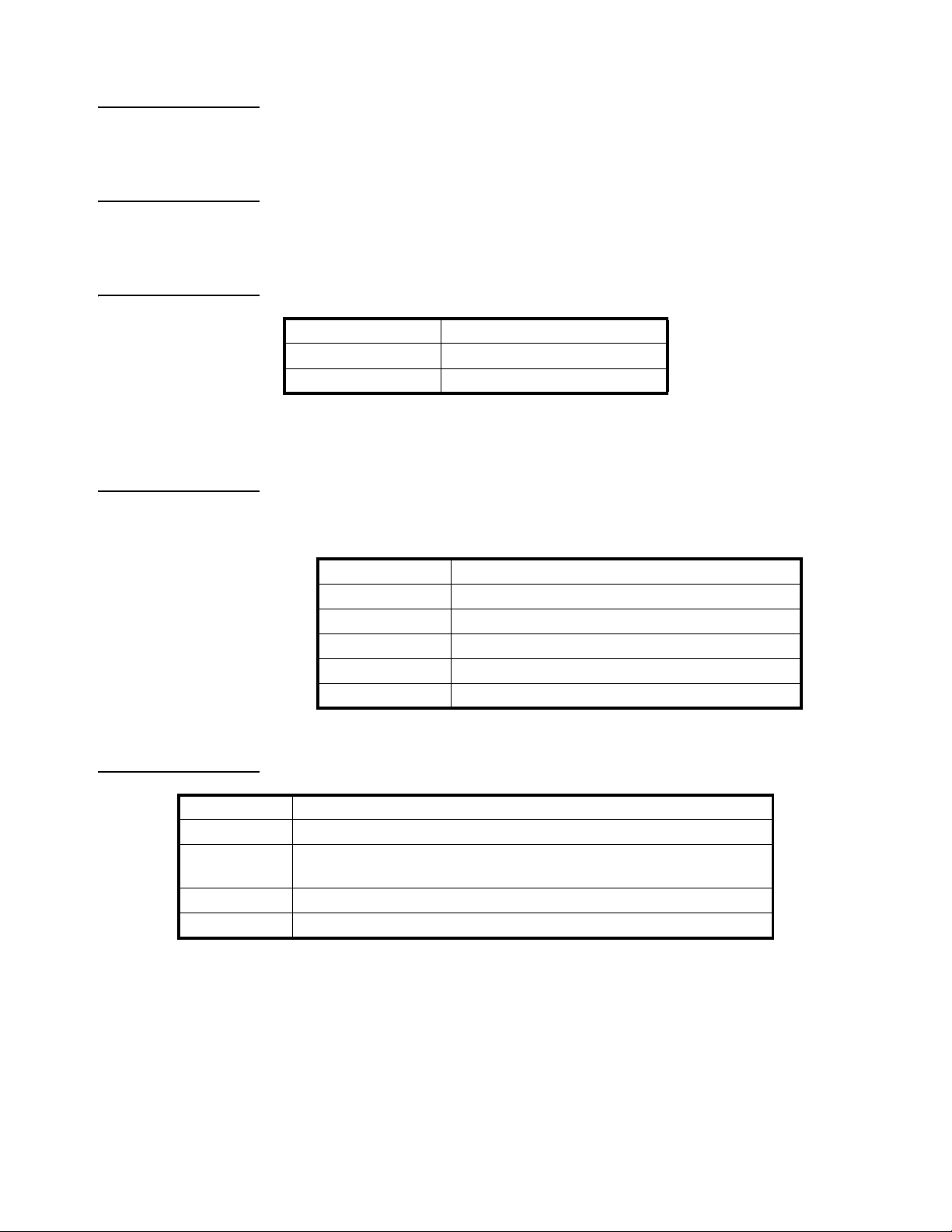
2.2.3 Display
l 5-digit,7-segment, 0.625" (16mm) LCD
2.2.4 Keypad
l 4 push button keys
2.2.5 Environment
Working temperature 5° to 35°C
Storage temperature -10°C to 70°C
Humidity ≤95% RH without condensation
2.2.6 Load Cell Excitation
Because more than one load cell can be used on a scale, the following are required for
the load cell set to be used with this indicator.
2.2.7 Communication
Mode Full-duplex or only output mode can be selected
Baud Rate Selectable: 1200-2400-4800-9600-19200 bps
Data Format 7 data bits, even or odd parity, 1 stop bit
8 data bits, non-parity, 1 stop bit
Protocol 7 selected protocols (one compatible with NCI standard SCP-01)
Output Data gross weight, net weight, tare weight, indicator displaying weight, weighing unit etc.
Voltage 4.4VDC
Max. Current 55mA (can power 4-350 ohm loadcells)
Signal connection 4 or 6 lead with sense leads
Max Sensitivity 0.3mV/V to +3mV/V (must be fit to >0.2µV
Input Resistor ≥80 Ω
Output Resistor <10 KΩ
/display grad)
MS140/300 User Instructions 7
Page 10
3 Introduction
d=Max
ZERO
NET
lb
kg
oz
This chapter introduces indicator mounting, display and keypad operation in normal
weigh mode.
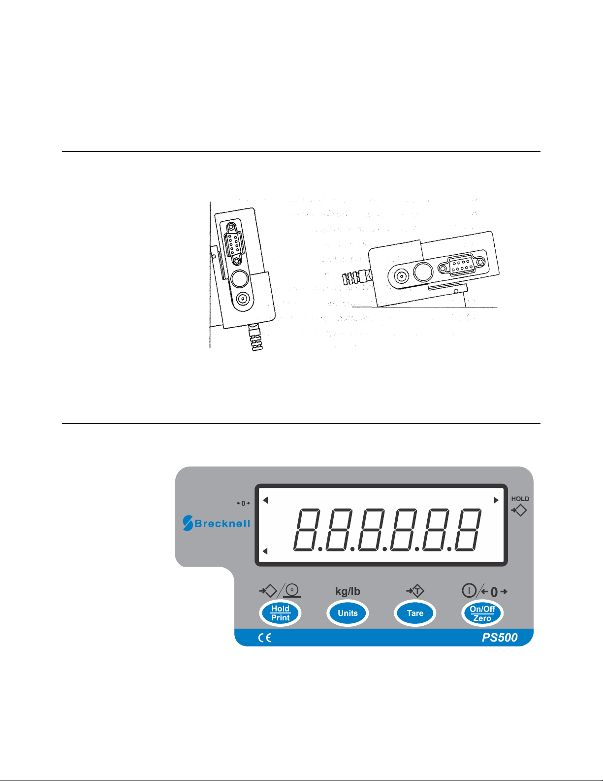
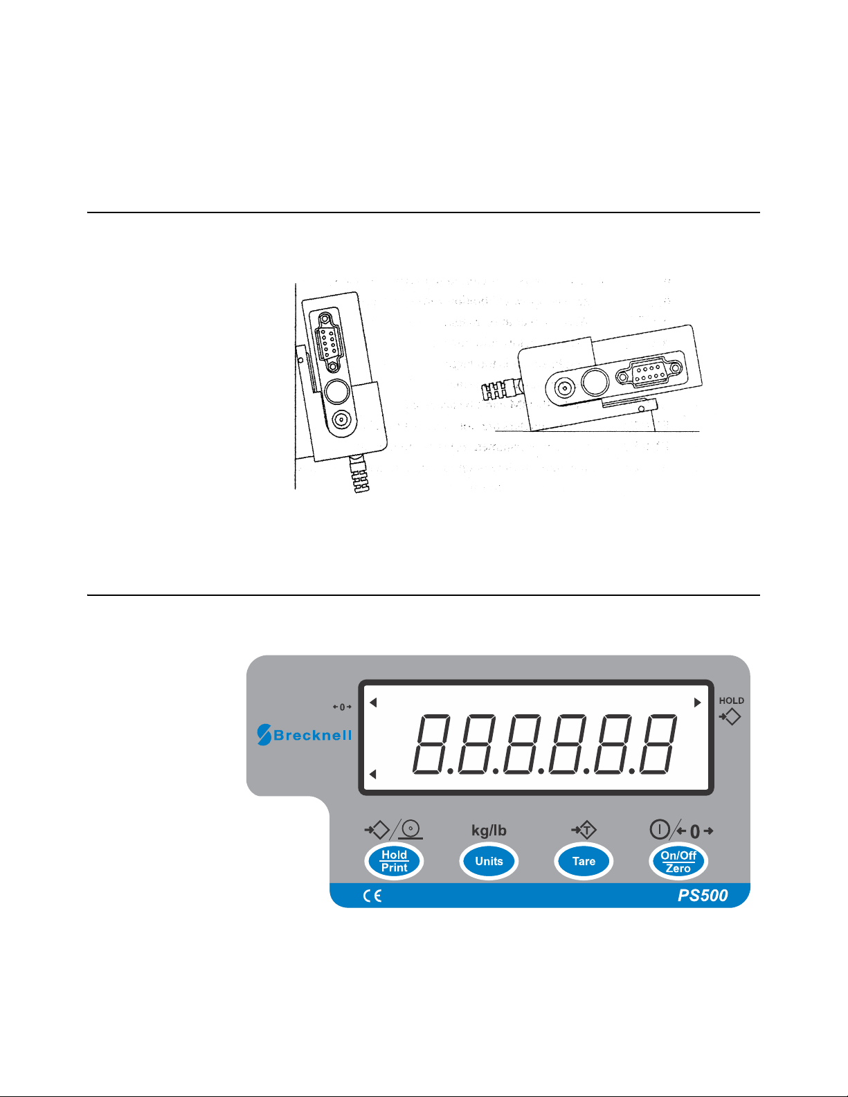
3.1 Indicator Mounting
The PS-500 is supplied with an ABS plastic bracket. Wall mount vertically or bench
mount horizontally depending on your needs.
3.2 Front Panel
The front panel incorporates the display and keypad.
8 MS140/300 User Instructions
Page 11
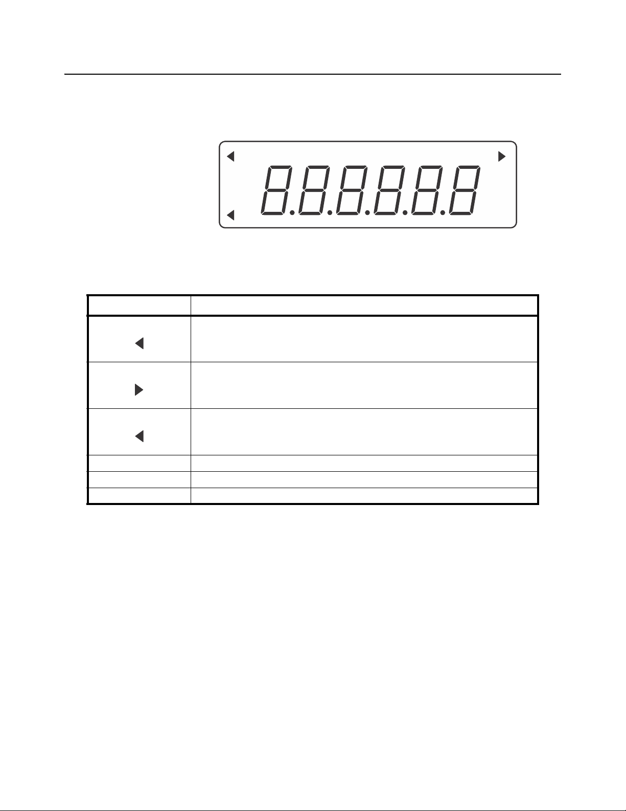
3.3 Display
Max
d=
lb
kg
oz
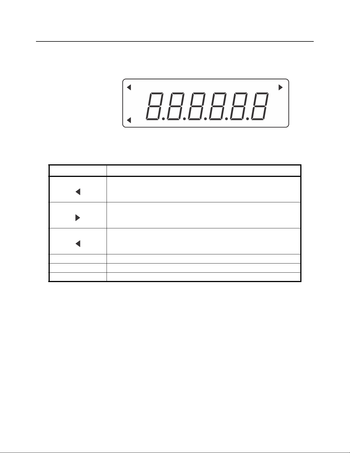
Display Symbol Description
ZERO The scale is at zero point and the gross weight is 0.
The PS-500 indicator utilizes a 7 segment LCD (Liquid Crystal Display) providing the
weight and system information.
Arrows will illuminate to designate the current mode.
Figure 3.1 PS-500 Display
Table 3.1 LCD Display Annunciators and Definitions
HOLD The scale is in HOLD mode.
The current live weight is being displayed when the arrow flashes. The current weight is
locked when the arrow does not flash.
NET Indicates net mode and the tare weight is not 0.
lb Indicates the current unit of measure is lb.
oz Indicates the current unit of measure is oz.
kg Indicates the current unit of measure is kg.
MS140/300 User Instructions 9
Page 12
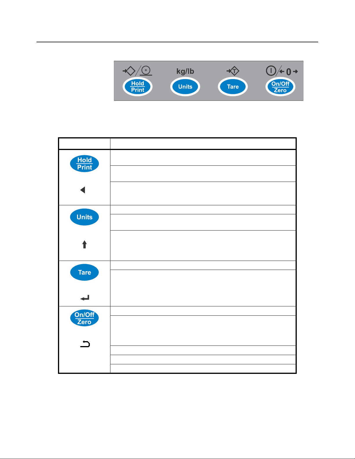
3.4 Keyboard
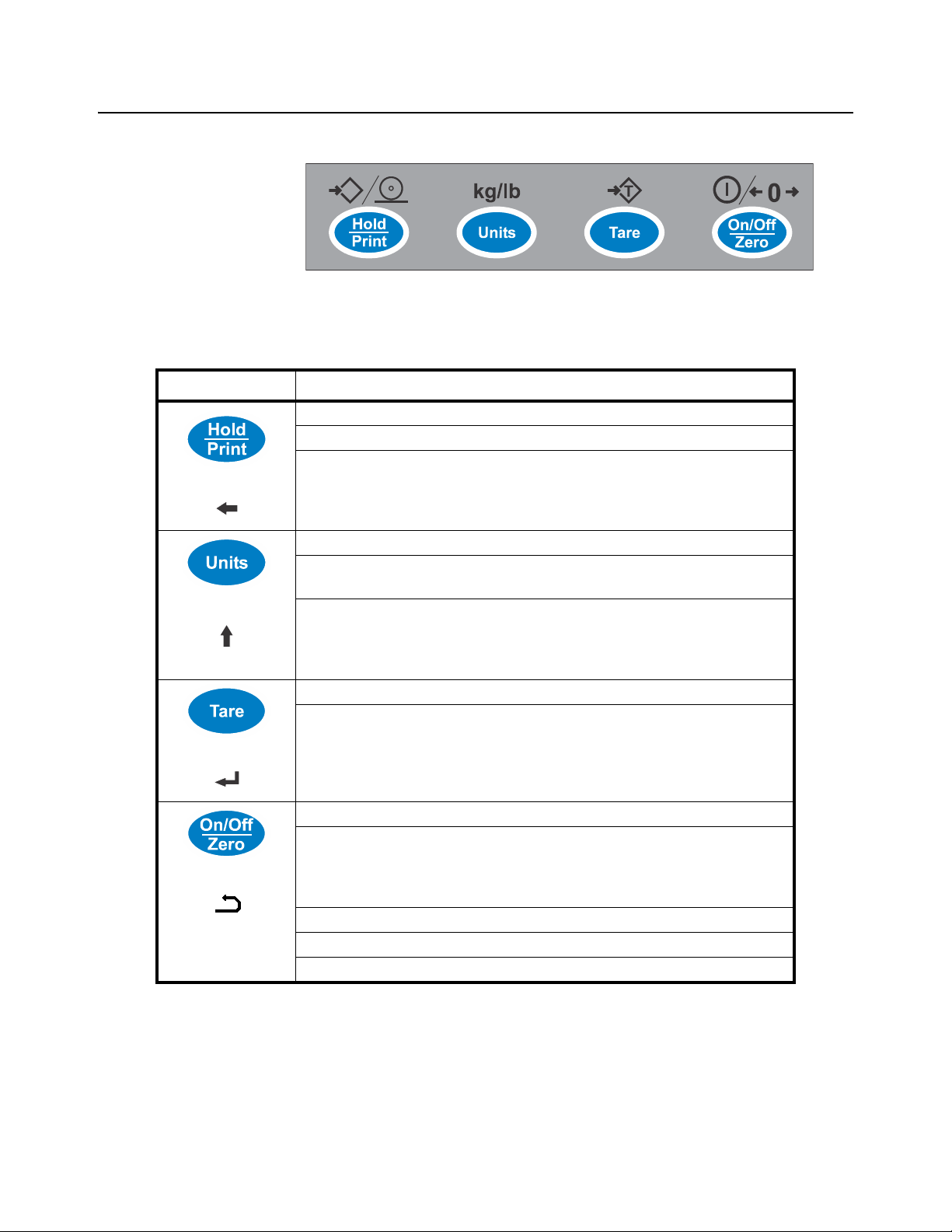
Key Function
The keyboard consists of four keys, some of which have multiple functions.
Figure 3.2 SBI-521 Keypad
Table 3.2 Function of the Keys (Normal Working Mode)
If this key is only set for HOLD (P2=0), press to enter or exit the HOLD mode.
If this key is only set for PRINT (P2=1), press to output the data according to P4 setting.
If this key is only set for HOLD and PRINT (P2=2), press to output data according to P4
setting and hold the current weight.
Choose weighing units; lb, kg, lb:oz
Note: The weighing units that can be used are restricted by display division, and
calibration weight unit (restricted by P8, P9, and P10)
For example, if the calibration unit is kg; calibration display resolution is 50kg (that
means: P8=5, P9=0, P10=0). If the UNIT key is pressed to choose weighing units, lb or
lb:oz are not allowed to choose since the display resolution of 100lb or 2000oz is not
available to this indicator.
Tare function
This function can be activated only when the scale is in stable mode and the gross
weight is not a negative value.
Power on
Zero function: When the weight is within zero range, it will activate as ZERO function
and clear the tare weight. When the weight is not within the zero setting range (P13),
the scale will show 0----- (zero point is over the setting range) or 0_____ (zero is below
the setting range).
Power off
ignore modification
Prepare to exit from current working mode
10 MS140/300 User Instructions
Page 13
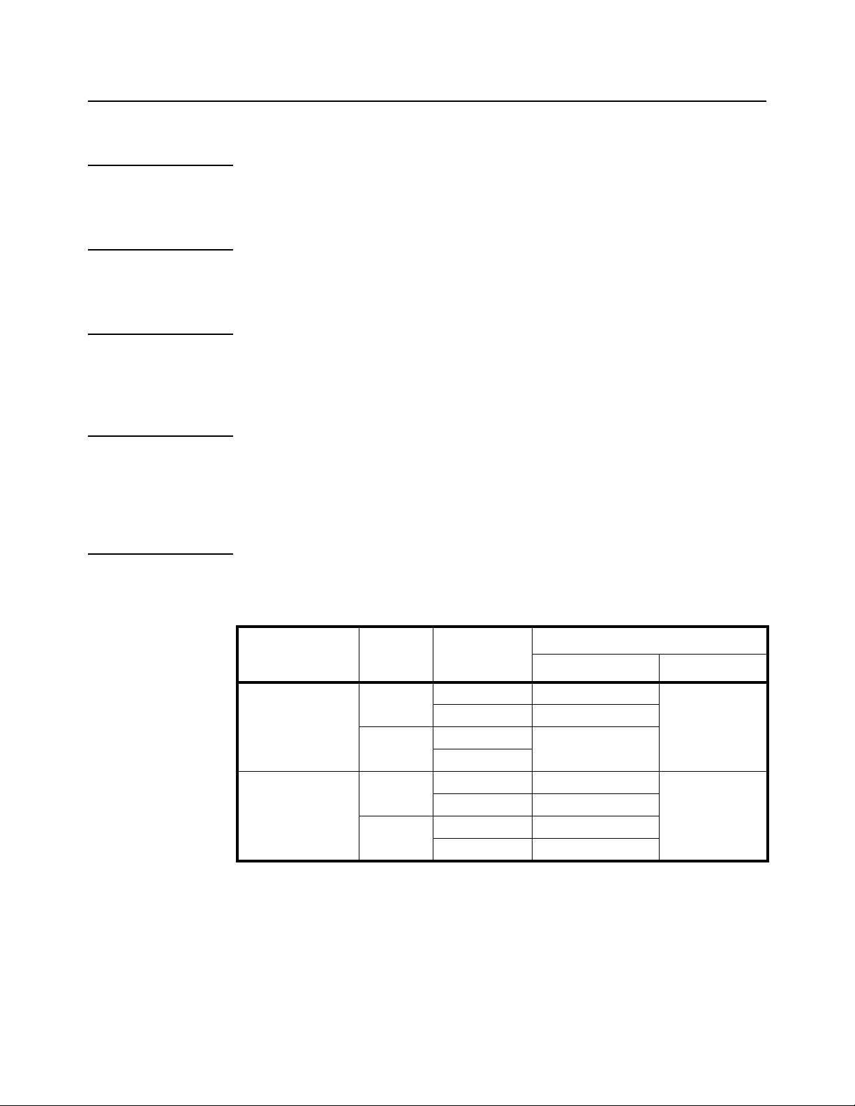
3.5 Navigating the Weigh Mode
3.5.1 Power the Indicator
Turn the indicator on or off with the [ON/OFF] key.
3.5.2 Enter or Exit the HOLD Mode
Press the [HOLD] key.
3.5.3 Zero
When the weight is stable and within the zero range, press the [ZERO] key to set a new
zero point. Refer to Table 3.3 for zero limitations.
3.5.4 Tare
When the gross weight is larger than zero and the scale is stable, press the [TARE]
key. The indicator will show a net weight of zero and the arrow to the right of NET will
be illuminated. Refer to Table 3.3 for tare limitations.
3.5.5 Clear Tare Weight
Remove any weight on platform and wait until the scale is stable. Press the [TARE] key.
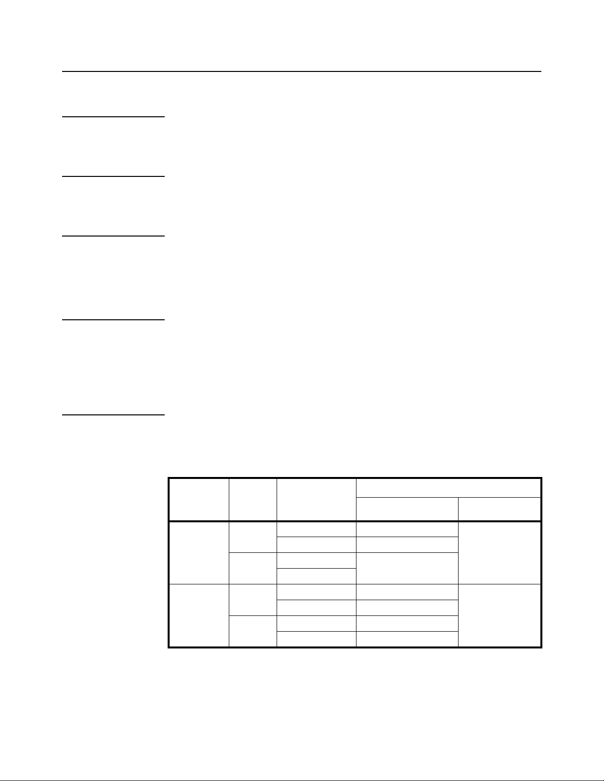
Standard
USA ≤0 no No action Zero
Canada ≤0 no No action Zero
Table 3.3 Zero and Tare Limitations
Weight on
platform
>0 no Tare
>0 no Tare
Data in TARE
memory unit
yes Clear the tared weight
yes
yes Clear the tared weight
yes No action
Tare key Zero key
key function
MS140/300 User Instructions 11
Page 14
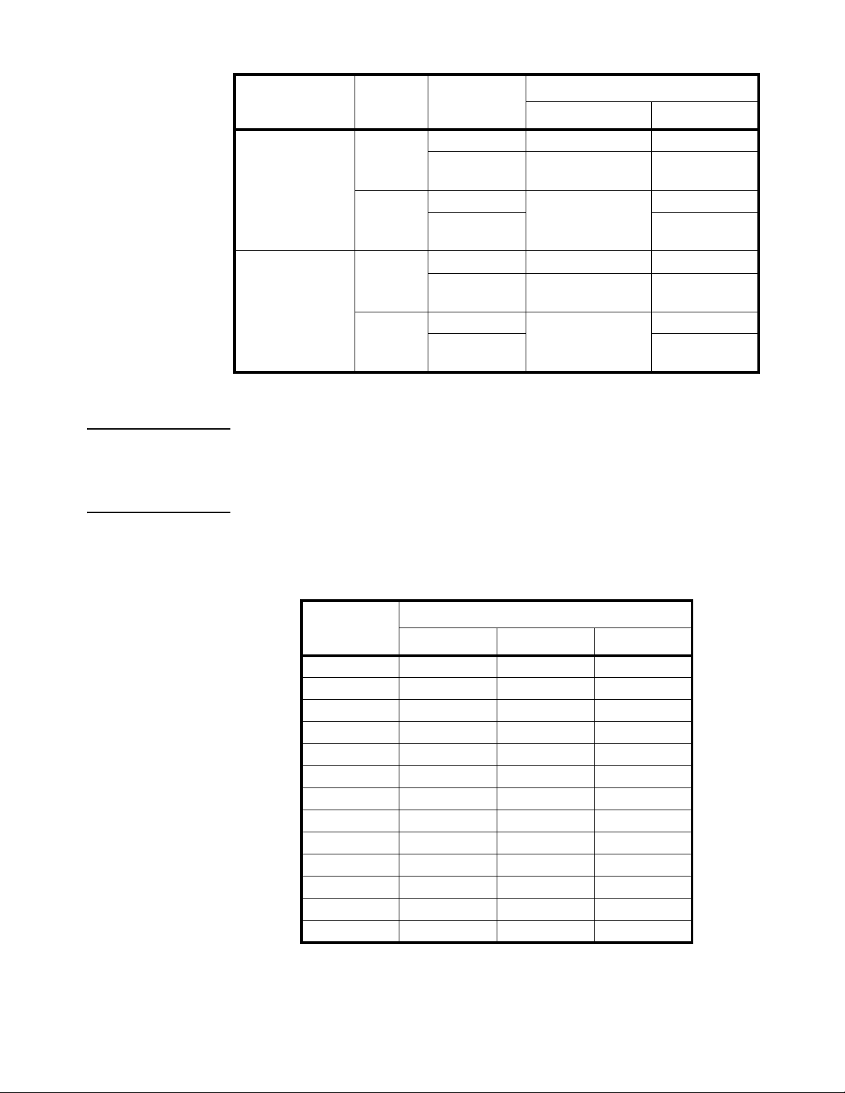
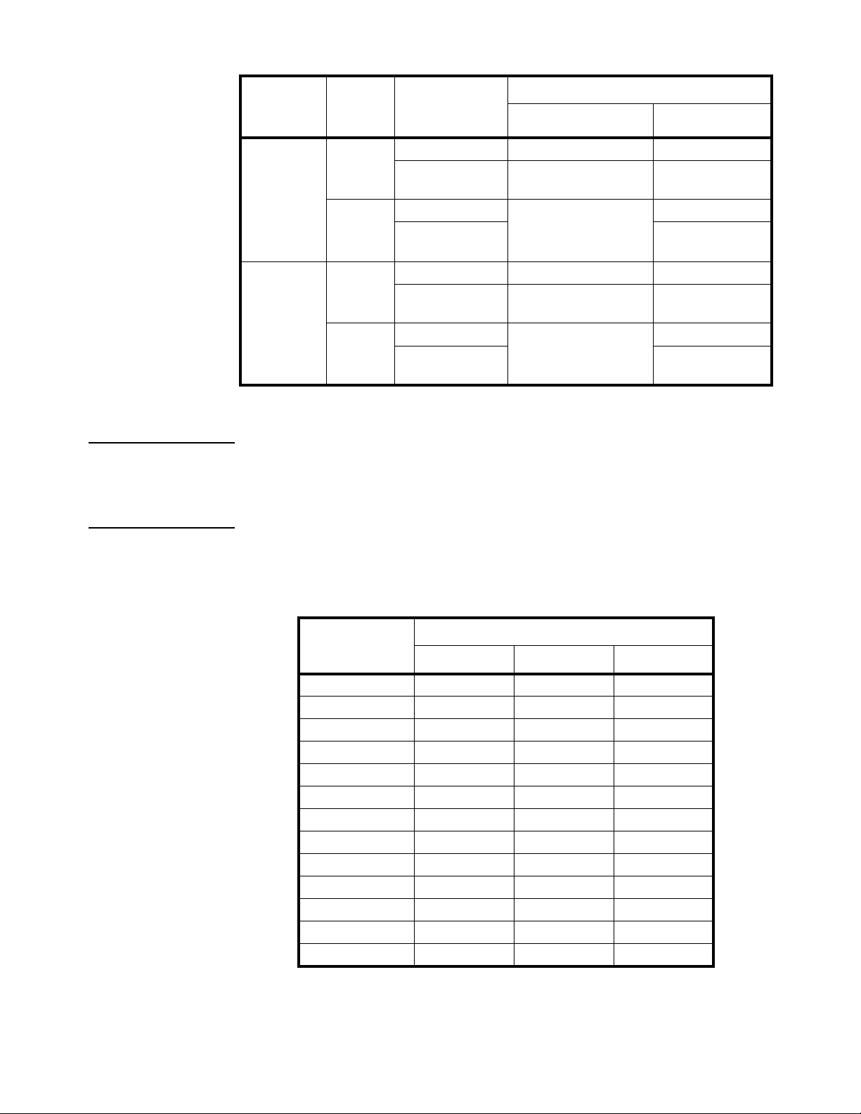
Standard
Weight on
platform
Data in TARE
memory unit
key function
Tare key Zero key
Europe
None
(same with Europe)
3.5.6 Output Data (Print)
When scale is stable press the [PRINT] key.
3.5.7 Change Weight Unit
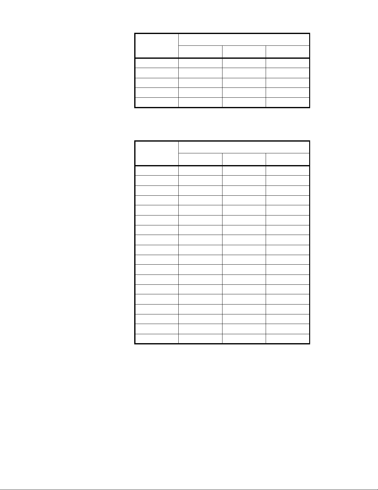
Press the [UNIT] key to select kg, lb or lb:oz. Note: under some conditions lb:oz is not
available. Please refer the following tables.
≤0 no No action Zero
yes Clear the tared weight Zero and clear the
tared weight
>0 no Tare Zero
yes Zero and clear the
tared weight
≤0 no No action Zero
yes Clear the tared weight Zero and clear the
tared weight
>0 no Tare Zero
yes Zero and clear the
tared weight
Table 3.4 Use kg as Primary Unit
Calibration
Division Value
0.0001kg 0.0001kg 0.0002lb Not available
0.001kg 0.001kg 0.002lb Not available
0.01kg 0.01kg 0.02lb 0.5oz
0.1kg 0.1kg 0.2lb Not available
1kg 1kg 2lb Not available
10kg 10kg 20 lb Not available
0.0002kg 0.0002kg 0.0005 lb Not available
0.002kg 0.002kg 0.005 lb 0.1 oz
0.02kg 0.02kg 0.05 lb 1 oz
0.2kg 0.2kg 0.5 lb Not available
2kg 2kg 5 lb Not available
20kg 20kg 50 lb Not available
0.0005kg 0.0005kg 0.001 lb Not available
kg lb lb:oz
Display Division Value
12 MS140/300 User Instructions
Page 15
Calibration
Division Value
kg lb lb:oz
Display Division Value
0.005kg 0.005kg 0.01 lb 0.2 oz
0.05kg 0.05kg 0.1 lb 2oz
0.5kg 0.5kg 1 lb Not available
5kg 5kg 10 lb Not available
50kg 50kg Not available Not available
Table 3.5 Use lb as Primary Unit
Calibration
Division Value
kg lb lb:oz
Display Division Value
0.0001lb Not available 0.0001lb Not available
0.001 lb 0.0005 kg 0.001 lb Not available
0.01 lb 0.005 kg 0.01 lb 0.2 oz
0.1 lb 0.05 kg 0.1 lb 2 oz
1 lb 0.5 kg 1 lb Not available
10 lb 5 kg 10 lb Not available
0.0002 lb 0.0001 kg 0.0002 lb Not available
0.002 lb 0.001 kg 0.002 lb Not available
0.02 lb 0.01 kg 0.02 lb 0.5 oz
0.2 lb 0.1 kg 0.2 lb Not available
2 lb 1 kg 2 lb Not available
20 lb 10 kg 20 lb Not available
0.0005 lb 0.0002 kg 0.0005 lb Not available
0.005 lb 0.002 kg 0.005 lb 0.1 oz
0.05 lb 0.02 kg 0.05 lb 1 oz
0.5 lb 0.2 kg 0.5 lb Not available
5 lb 2 kg 5 lb Not available
50 lb 20 kg 50 lb Not available
MS140/300 User Instructions 13
Page 16

3.6 Hold Function
HOLD function can be used to freeze a displayed number. In this mode, the scale can
capture a dynamic number, hold a stable number, or average a unstable number and
then HOLD (freeze) this number temporarily for the user to view or record.
The HOLD function can be used in normal weighing mode, counting mode and percent
weighing mode. After entering HOLD mode, the speed of A/D converter can be
increased to 80Hz (if USER-HOLD-AD.H.SPD is set to YES) from original 10Hz for
some dynamic weighing applications.
It is possible to weigh restless weighing samples such as live animals or moving objects
within the hold function. The indicator provides special mode settings to accommodate
weight movements.
3.6.1 Access the Hold Mode
To enter the HOLD mode, press the [HOLD] key while in the normal weighing mode.
14 MS140/300 User Instructions
Page 17
4 Setup Mode
To set up the indicator, you must first enter the appropriate menu mode. The front panel
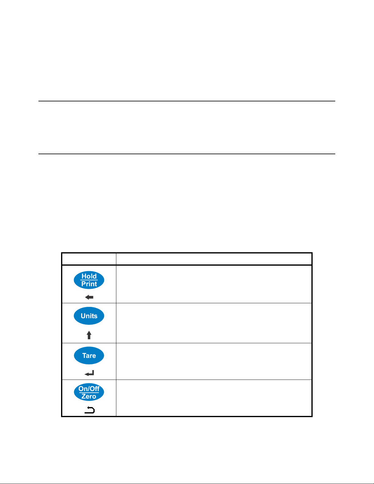
keys become directional navigators to move around in the menus. See Table 4.1 for
details.
4.1 Entering the Setup Menu
1. Press and hold the [ON/OFF/ZERO] and [UNIT] keys unit setup is displayed.
1a. This indicator offers 19 different setup parameters.
4.2 Navigating the Setup Menu
1. Once setup is displayed, use the [UNIT] key to change the flashed digits
and use the [HOLD/PRINT] key to shift the flashed position.
The parameter will be designated in the following format:
PN.x or PNN.xx - P is parameter; N or NN is the parameter number; x or xx is the choice
within the parameter. Refer to Table 4.2 for parameters and the options for each
parameter.
2. Use the [TARE] key to confirm the entry, save the data and go to the next
parameter.
Table 4.1 Key Functions in the Setup Mode
Key Function
Move cursor from right to left.
Scroll selected digit (0 - 9).
Cycles through the parameters.
Confirm parameter choice selection.
Exit from setup mode to normal work mode.
MS140/300 User Instructions 15
Page 18
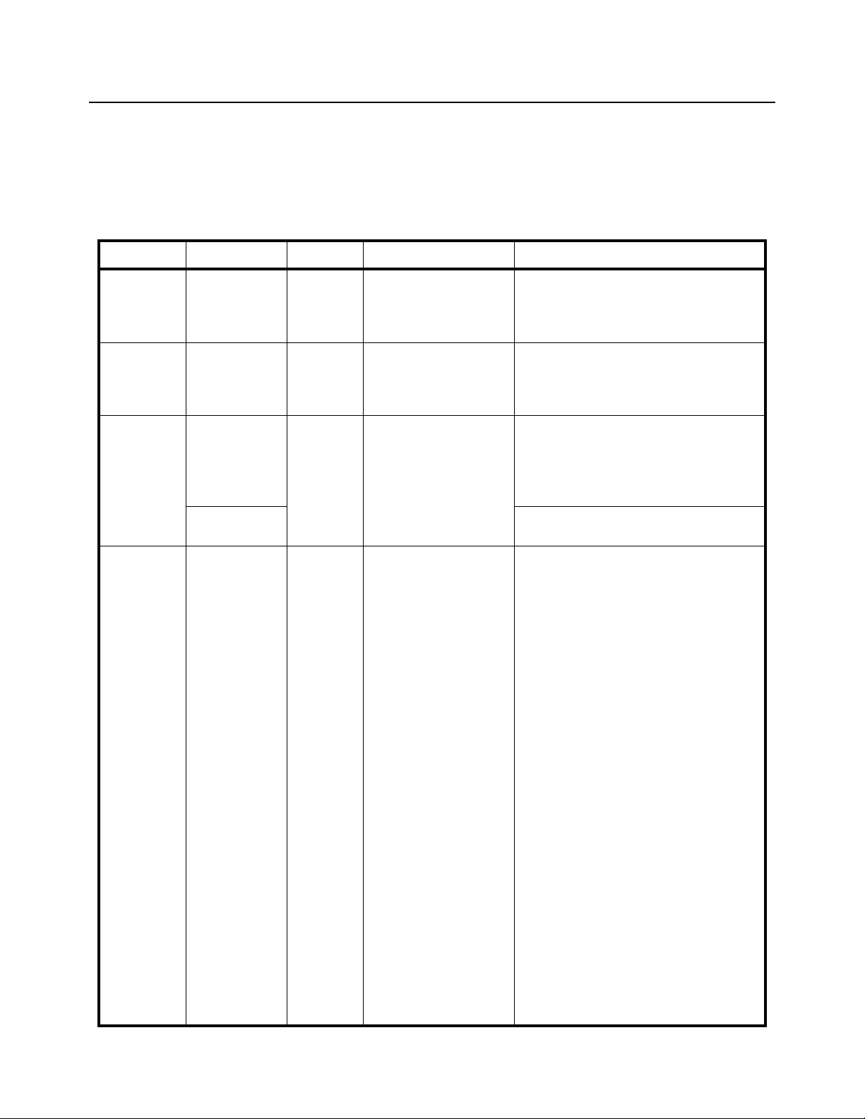
4.3 Setup Menu Parameters
This section provides more detailed descriptions of the selections found in the Setup
Menu.
The menu table shows the options and default parameter in LCD display format to
coinside with the actual display.
Table 4.2 Parameter Choices and Explanations
SubMenu1 Option Default Parameter Description Comment
P1 00-15 05 Auto off time 00 = no auto off
01-15 = auto off time in minutes. The scale will
automatically turn off after specified time when
there has been no flucuation of weight.
p2 0-2 2 Hold key function 0 = only HOLD function
1 = only PRINT function
2 = HOLD and PRINT function. Short press for
Print function and long press for Hold function.
p3 0-2 2 Hold mode function 0 = no hold function
1 = hold larger weight reading
2 = auto release hold function when weigh is
below 10d and auto hold new stable weigh
(more than 10d)
3-50 3-50 = unchangeable reading when the variety
is within ±3-50d
p4 0-7 2 Output of print data 0 = no RS232 function. Will not transmit or
receive data.
1 = output display data when PRINT is pressed
and weight reading is stable.
<LF><weight reading, minus sign, decimal
point, unit><CR><EXT>
2 = output gross, tare and net weight and weigh
unit when PRINT pressed.
<LF><Gross:weight reading, minus sign,
decimal point, unit><CR><EXT>
<Tare:weight reading, decimal point,
unit><CR><EXT>
<Net:weight reading, minus sign, decimal point,
unit><CR><EXT>
3 = continuously output displayed weight
reading and unit. No data will be received.
Output format same as choice 1.
4 = continuously output gross, tare, net weight
and weigh unit. No data will be received. Output
formats same as choice 2.
5 = output display data and weigh unit one time
when scale is stable. Output format same as
choice 1.
6 = output gross, tare, net weight and weigh
unit one time when scale become stable.
Output formats same as choice 2.
7 = Bio-RS232 data output, compatible to NCISP1
16 MS140/300 User Instructions
Page 19
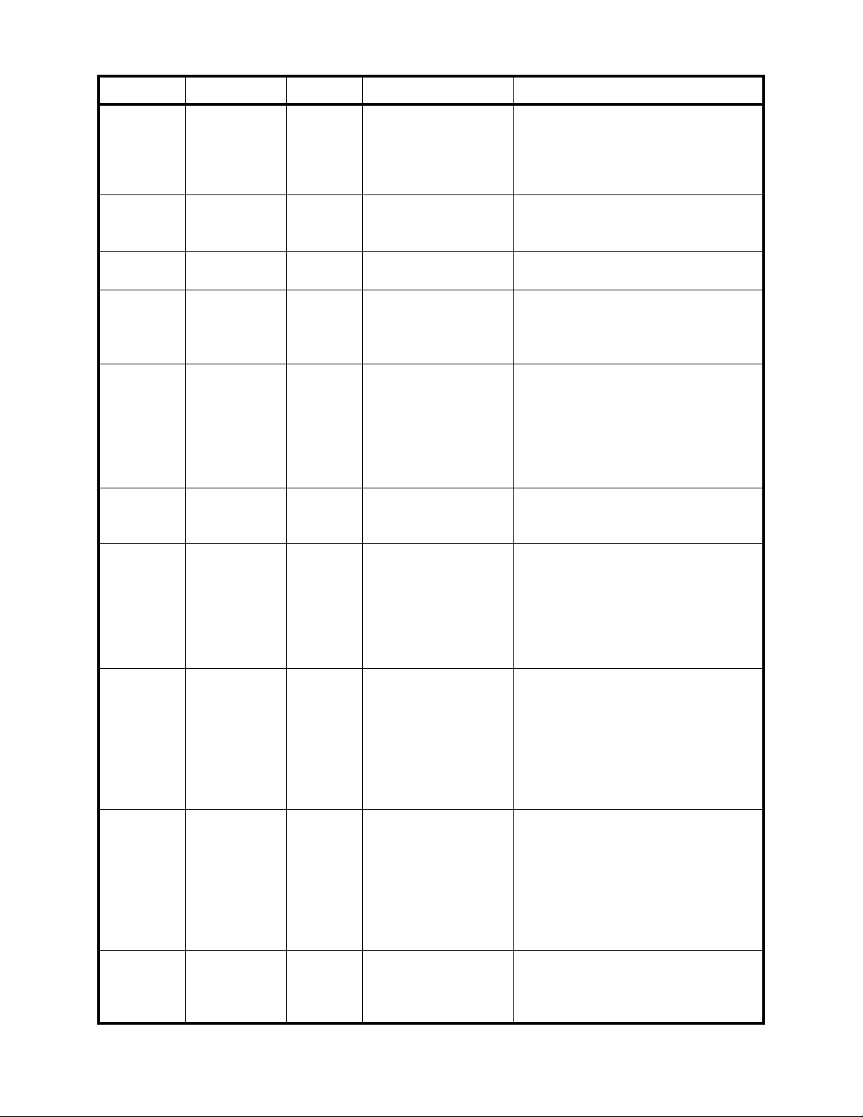
SubMenu1 Option Default Parameter Description Comment
P5 0-4 3 Baud rate for RS-232 0 = 1200 bps
1 = 2400 bps
2 = 4800 bps
3 = 9600 bps
4 = 19200 bps
p6 0-2 0 RS-232 protocol 0 = 8NO
1 = 7O1
2 = 7E1
p7 00-31 9 Scale resolution select Refer to Table 4.3 for resolution choices and
values.
P8 0-2 1 Calibration division size Refer to Table 4.4 and Table 4.5
0 = 1
1 = 2
2 = 5
p9 0-5 1 Decimal point in calibration Refer to Table 4.4 and Table 4.5
0 = 1
1 = 0.1
2 = 0.01
3 = 0.001
4 = 0.0001
5 = 10
p10 0,1 1 Calibration unit Refer to Table 4.4 and Table 4.5
0 = kg
1 = lb
p11 0-6 6 Weigh units enable 0 = only kg
1 = only lb
2 = only lb:oz
3 = kg or lb
4 = kg or lb:oz
5 = lb or lb:oz
6 = kg, lb, or lb:oz
p12 0-7 3 Power on zero range 0 = calibration zero -point +1%FS
1 = calibration zero -point +2%FS
2 = calibration zero-point +5%FS
3 = calibration zero-point +10%FS
4 = calibration zero-point +20%FS
5 = calibration zero-point +50%FS
6 = calibration zero-point +100%FS
7 = no limitation
p13 0-7 2
Zero range for [ZERO] key 0 = power-on zero-point +1%FS
1 = power-on zero-point +2FS
2 = power-on zero-point +5%FS
3 = power-on zero-point +10%FS
4 = power-on zero-point +20%FS
5 = power-on zero-point +50%FS
6 = power-on zero-point +100%FS
7 = no limitation
p14 0-2 2 Weight signal within power
on zero point range
0 = current weight
1 = calibration zero-point
2 = switch off zero point and power off tare
weight as current tare weight
MS140/300 User Instructions 17
Page 20
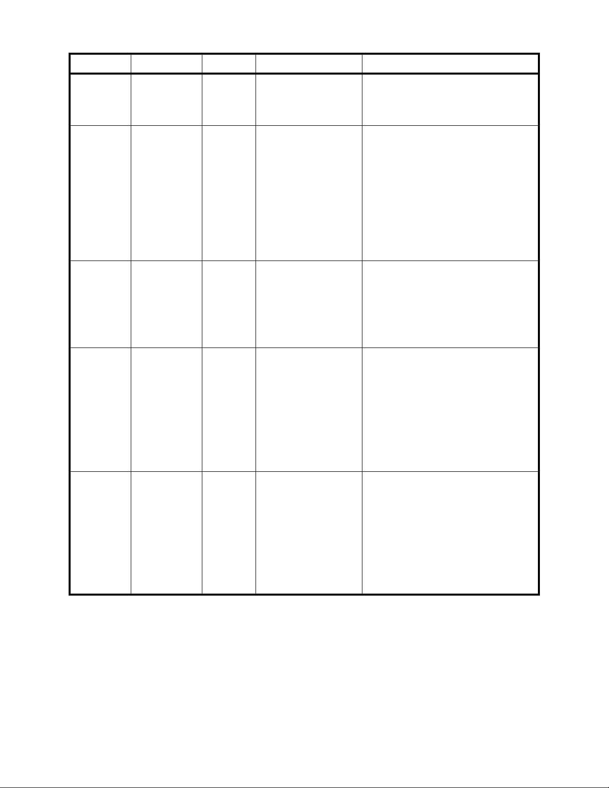
SubMenu1 Option Default Parameter Description Comment
p15 0-3 1 Weight signal not within
power on zero point range
0 = current weight
1 = calibration zero-point
2 = switch-off zero-point
3 = continuously display 0-----
p16 0-8 8 Zero tracking range Choose the zero tracking range as per the
stability of weighing system accuracy.
0 = 0d, no tracking
1 = +0.25d
2 = +0.5d
3 = +1d
4 = +1.5d
5 = +2d
6 = +3d
7 = +4d
8 = +5d
p17 0-3 2 Data filter intensity The larger the digit data filter intensity is
stronger and the speed of data updating is
lower.
0 = very weak
1 = weak
2 = middle
3 = strong
p18 0-9 1 Range of weight stability
checking
0 = +0.5d
1 = ±1d
2 = +2d
3 = +3d
4 = +4d
5 = +5d
6 = +6d
7 = +7d
8 = +8d
9 = +9d
p19 0-9 1 Overload limit range 0 = FS+0d
1 = FS+9d
2 = 101%FS
3 = 102%FS
4 = 105%FS
5 = 110%FS
6 = 120%FS
7 = 150%FS
8 = 200%FS
9 = no limitation
18 MS140/300 User Instructions
Page 21
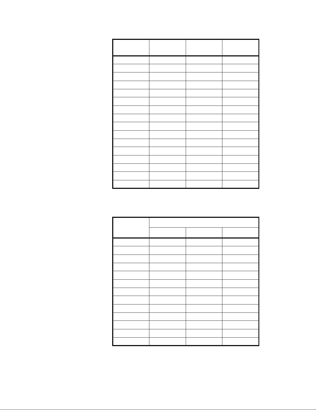
Table 4.3 Calibration Resolution (P7)
Parameter
Choice
Calibration
Resolution
Parameter
Choice
00 500 16 7500
01 600 17 8000
02 750 18 10000
03 800 19 12000
04 1000 20 15000
05 1200 21 20000
06 1500 22 25000
07 2000 23 30000
08 2400 24 35000
09 2500 25 40000
10 3000 26 50000
11 3500 27 60000
12 4000 28 70000
13 5000 29 75000
14 6000 30 80000
15 7000 31 100000
Calibration
Resolution
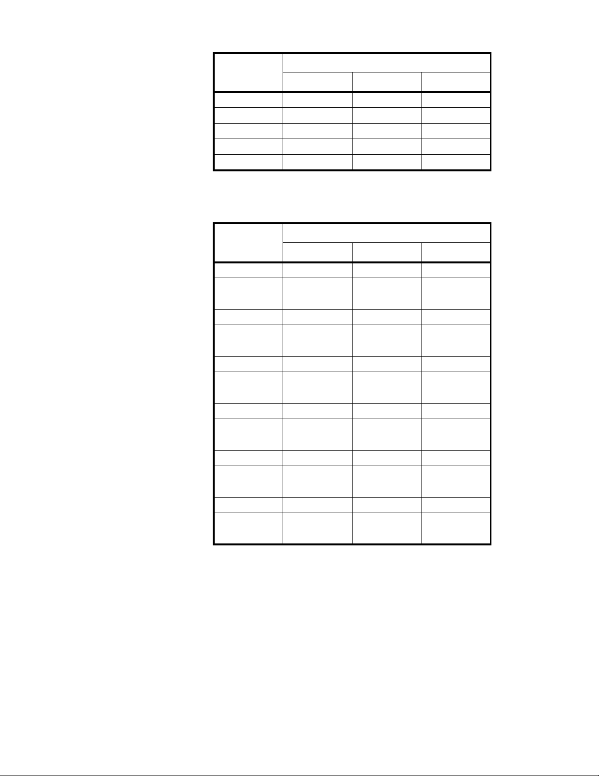
Table 4.4 Calibration Units (kg) per P8, P9 and P10
Calibration
Division Value
kg lb lb:oz
Display Division Value
0.0001kg 0.0001kg 0.0002lb Not available
0.001kg 0.001kg 0.002lb Not available
0.01kg 0.01kg 0.02lb 0.5oz
0.1kg 0.1kg 0.2lb Not available
1kg 1kg 2lb Not available
10kg 10kg 20 lb Not available
0.0002kg 0.0002kg 0.0005 lb Not available
0.002kg 0.002kg 0.005 lb 0.1 oz
0.02kg 0.02kg 0.05 lb 1 oz
0.2kg 0.2kg 0.5 lb Not available
2kg 2kg 5 lb Not available
20kg 20kg 50 lb Not available
0.0005kg 0.0005kg 0.001 lb Not available
MS140/300 User Instructions 19
Page 22
Calibration
Division Value
kg lb lb:oz
Display Division Value
0.005kg 0.005kg 0.01 lb 0.2 oz
0.05kg 0.05kg 0.1 lb 2oz
0.5kg 0.5kg 1 lb Not available
5kg 5kg 10 lb Not available
50kg 50kg Not available Not available
Table 4.5 Calibration Units (lb) per P8, P9 and P10
Calibration
Division Value
kg lb lb:oz
Display Division Value
0.0001lb Not available 0.0001lb Not available
0.001 lb 0.0005 kg 0.001 lb Not available
0.01 lb 0.005 kg 0.01 lb 0.2 oz
0.1 lb 0.05 kg 0.1 lb 2 oz
1 lb 0.5 kg 1 lb Not available
10 lb 5 kg 10 lb Not available
0.0002 lb 0.0001 kg 0.0002 lb Not available
0.002 lb 0.001 kg 0.002 lb Not available
0.02 lb 0.01 kg 0.02 lb 0.5 oz
0.2 lb 0.1 kg 0.2 lb Not available
2 lb 1 kg 2 lb Not available
20 lb 10 kg 20 lb Not available
0.0005 lb 0.0002 kg 0.0005 lb Not available
0.005 lb 0.002 kg 0.005 lb 0.1 oz
0.05 lb 0.02 kg 0.05 lb 1 oz
0.5 lb 0.2 kg 0.5 lb Not available
5 lb 2 kg 5 lb Not available
50 lb 20 kg 50 lb Not available
20 MS140/300 User Instructions
Page 23
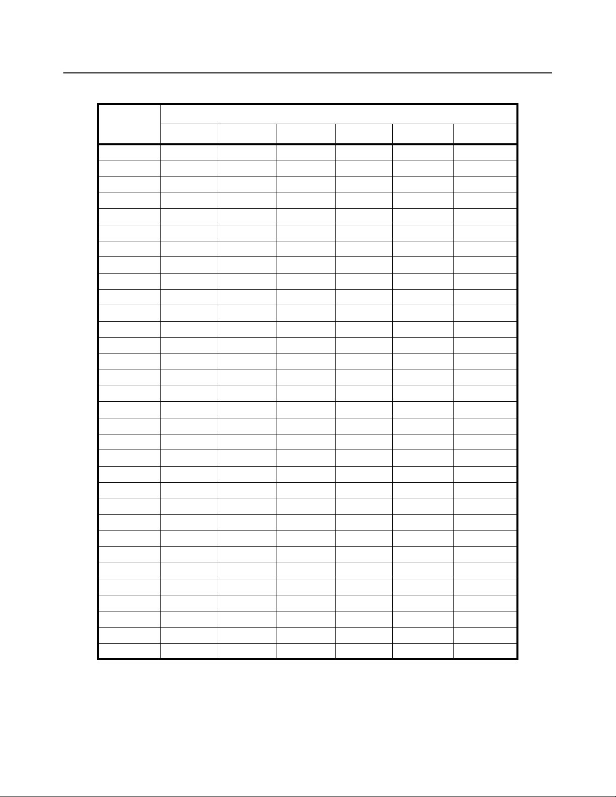
4.4 Relationship of Capacity and P7, P8 and P9 Settings
Table 4.6 Capacity Unit is kg or lb (Count by 1)
Resolution
set by P7
500 0.0500 0.500 5.00 50.0 500 5000
600 0.0600 0.600 6.00 60.0 600 6000
750 0.0750 0.750 7.50 75.0 750 7500
800 0.0800 0.800 8.00 80.0 800 8000
1000 0.1000 1.000 10.00 100.0 1000 10000
1200 0.1200 1.200 12.00 120.0 1200 12000
1500 0.1500 1.500 15.00 150.0 1500 15000
2000 0.2000 2.000 20.00 200.0 2000 20000
2400 0.2400 2.400 24.00 240.0 2400 24000
2500 0.2500 2.500 25.00 250.0 2500 25000
3000 0 .3000 3.000 30.00 300.0 3000 30000
3500 0.3500 3.500 35.00 350.0 3500 35000
4000 0.4000 4.000 40.00 400.0 4000 40000
5000 0.5000 5.000 50.00 500.0 5000 50000
6000 0.6000 6.000 60.00 600.0 6000 60000
7000 0.7000 7.000 70.00 700.0 7000 70000
7500 0.7500 7.500 75.00 750.0 7500 75000
8000 0.8000 8.000 80.00 800.0 8000 80000
10000 1.0000 10.000 100.00 1000.0 10000 100000
12000 1.2000 12.000 120.00 1200.0 12000 120000
15000 1.5000 15.000 150.00 1500.0 15000 150000
20000 2.0000 20.000 200.00 2000.0 20000 200000
25000 2.5000 25.000 250.00 2500.0 25000 250000
30000 3.0000 30.000 300.00 3000.0 30000 300000
35000 3.5000 35.000 350.00 3500.0 35000 350000
40000 4.0000 40.000 400.00 4000.0 40000 400000
50000 5.0000 50.000 500.00 5000.0 50000 500000
60000 6.0000 60.000 600.00 6000.0 60000 600000
70000 7.0000 70.000 700.00 7000.0 70000 700000
75000 7.5000 75.000 750.00 7500.0 75000 750000
80000 8.0000 80.000 800.00 8000.0 80000 800000
100000 10.0000 100.000 1000.00 10000.0 100000 1000000
0.0001 0.001 0.01 0.1 1 10
Division set by P8 (P8 = 0) and P9
MS140/300 User Instructions 21
Page 24
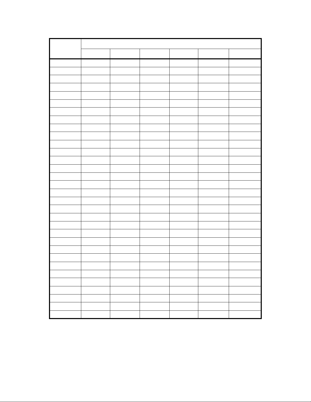
Table 4.7 Capacity Unit is kg or lb (Count by 2)
Resolution
set by P7
0.0002 0.002 0.02 0.2 2 20
Division set by P8 (P8 = 1) and P9
500 0.1000 1.000 10.00 100.0 1000 10000
600 0.1200 1.200 12.00 120.0 1200 12000
750 0.1500 1.500 15.00 150.0 1500 15000
800 0.1600 1.600 16.00 160.0 1600 16000
1000 0.2000 2.000 20.00 200.0 2000 20000
1200 0.2400 2.400 24.00 240.0 2400 24000
1500 0.3000 3.000 30.00 300.0 3000 30000
2000 0.4000 4.000 40.00 400.0 4000 40000
2400 0.4800 4.800 48.00 480.0 4800 48000
2500 0.5000 5.000 50.00 500.0 5000 50000
3000 0.6000 6.000 60.00 600.0 6000 60000
3500 0.7000 7.000 70.00 700.0 7000 70000
4000 0.8000 8.000 80.00 800.0 8000 80000
5000 1.0000 10.000 100.00 1000.0 10000 100000
6000 1.2000 12.000 120.00 1200.0 12000 120000
7000 1.4000 14.000 140.00 1400.0 14000 140000
7500 1.5000 15.000 150.00 1500.0 15000 150000
8000 1.6000 16.000 160.00 1600.0 16000 160000
10000 2.0000 20.000 200.00 20000.0 20000 200000
12000 2.4000 24.000 240.00 2400.0 24000 240000
15000 3.0000 30.000 300.00 3000.0 30000 300000
20000 4.0000 40.000 400.00 4000.0 40000 400000
25000 5.0000 50.000 500.00 5000.0 50000 500000
30000 6.0000 60.000 600.00 6000.0 60000 600000
35000 7.0000 70.000 700.00 7000.0 70000 700000
40000 8.0000 80.000 800.00 8000.0 80000 800000
50000 10.0000 100.000 1000.00 10000.0 100000 1000000
60000 12.0000 120.000 1200.00 12000.0 120000 1200000
70000 14.0000 140.000 1400.00 14000.0 140000 1400000
75000 15.0000 150.000 1500.00 15000.0 150000 1500000
80000 16.0000 160.000 1600.00 16000.0 160000 1600000
100000 20.0000 200.000 2000.00 20000.0 200000 2000000
22 MS140/300 User Instructions
Page 25
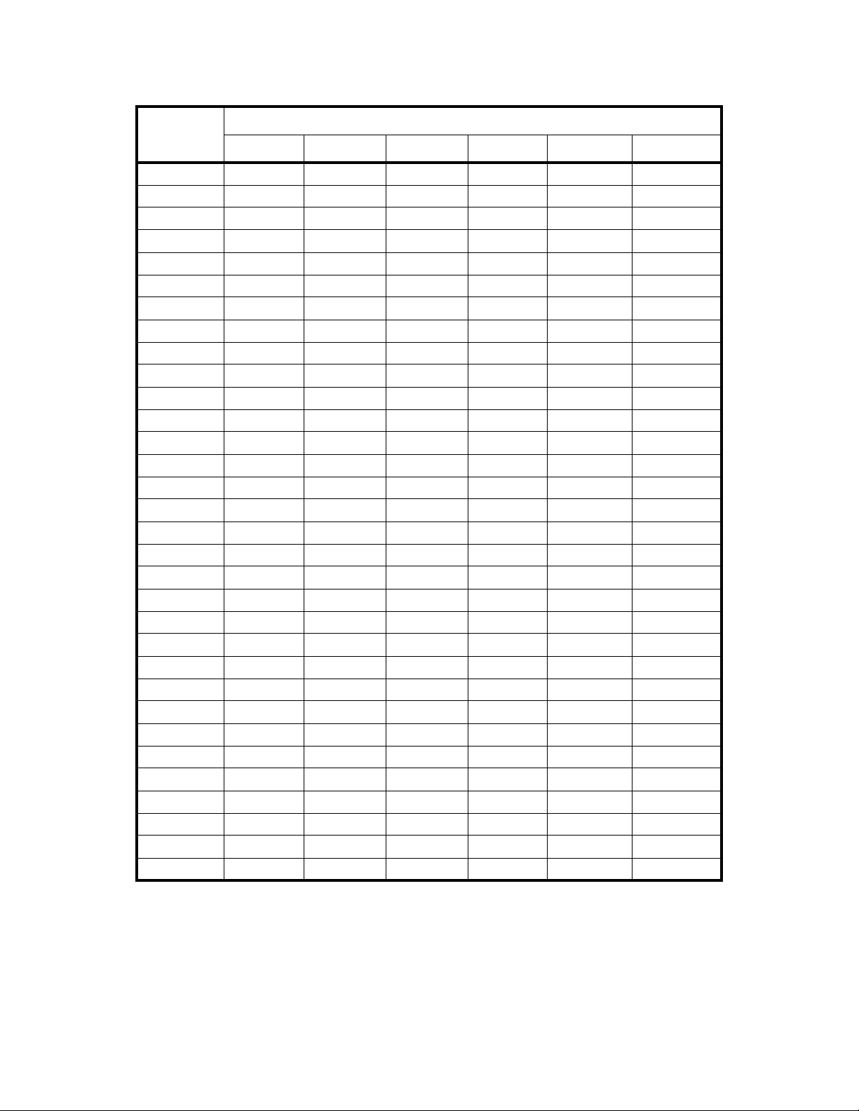
Table 4.8 Capacity Unit is kg or lb (Count by 5)
Resolution
set by P7
0.0005 0.005 0.05 0.5 5 50
Division set by P8 (P8 = 2) and P9
500 0.2500 2.5000 25.00 250.0 2500 25000
600 0.3000 3.000 30.00 300.0 3000 30000
750 0.3750 3.750 37.50 375.0 3750 37500
800 0.4000 4.000 40.00 400.0 4000 40000
1000 0.5000 5.000 50.00 500.0 5000 50000
1200 0.6000 6.000 60.00 600.0 6000 60000
1500 0.7500 7.500 75.00 750.0 7500 75000
2000 1.0000 10.000 100.00 1000.0 10000 100000
2400 1.2000 12.000 120.00 1200.0 12000 120000
2500 1.2500 12.500 125.00 1250.0 12500 125000
3000 1.5000 15.000 150.00 1500.0 15000 150000
3500 1.7500 17.500 175.00 17500.0 17500 175000
4000 2.0000 20.000 200.00 20000.0 20000 200000
5000 2.5000 25.000 250.00 2500.0 25000 250000
6000 3.0000 30.000 300.00 3000.0 30000 300000
7000 3.5000 35.00 350.00 3500.0 35000 350000
7500 375.00 37.500 375.00 3750.0 37500 375000
8000 4.0000 40.000 400.00 4000.0 40000 400000
10000 5.0000 50.000 500.00 5000.0 50000 500000
12000 6.0000 60.000 600.00 6000.0 60000 600000
15000 7.5000 75.000 750.00 7500.0 75000 750000
20000 10.0000 100.000 1000.00 10000.0 100000 1000000
25000 12.5000 125.000 1250.00 12500.0 125000 1250000
30000 15.0000 150.000 1500.00 15000.0 150000 1500000
35000 17.5000 175.000 1750.00 17500.0 175000 1750000
40000 20.0000 200.000 2000.00 20000.0 200000 2000000
50000 25.0000 250.000 2500.00 25000.0 250000 2500000
60000 30.0000 300.000 3000.00 30000.0 30000 3000000
70000 35.0000 350.000 3500.00 35000.0 350000 3500000
75000 37.5000 375.000 3750.00 37500.0 375000 3750000
80000 40.0000 400.000 4000.00 40000.0 400000 4000000
100000 50.0000 500.000 5000.00 50000.0 500000 5000000
MS140/300 User Instructions 23
Page 26

4.5 Exit the Setup Menu
1. Power off the indicator by pressing and holding the [ZERO/ON/OFF] key.
2. Move the slide switch on the rear cover back to the left and replace the metal
protective plate. Refer to section 4.2 for location.
3. Turn the indicator back on by pressing the [ON] key. The display will go
through a digit check, then settle into Normal Operating mode. All front panel
keys will now return to their normal mode of operation.
24 MS140/300 User Instructions
Page 27
5 Calibration
The config/cal switch must be set to the ON position in order to calibrate the indicator.
NOTE: More than 25% of the full scale weight is needed for calibration.
5.1 Calibration Mode
Before calibration, prepare the standard weight (more than 25% of full scale).
1. Remove any weight on the scale.
2. When in normal weighing mode, press and hold down [TARE] and [ON/OFF/
ZERO] keys to enter calibration mode.
3. When the indicator displays cal-, the scale is ready for calibration. Press
[TARE] to confirm and go to next step or press [ON/OFF/ZERO] to exit the
calibration mode.
4. The indicator will display cap--.
4a. This means the following data is the full capacity according to your setting of
display resolution (P7), display division value (P8), location of decimal point in
calibration unit (P9) and capacity unit in calibration (P10).
4b. If the setting of full scale is more than 199999 (regardless of decimal point and
weight unit), the full scale capacity will be shown by first four digits and last
four digits: Hxxx and Lxxx.
5. Press [TARE] to go to next step directly, press [ON/OFF/ZERO] to exit the
calibration mode or after a few seconds it will automatically to next step.
6. The scale will automatically display the setting of division. Firstly it will display
d.--, and then the data according to your setting of P8, P9 and P10. Refer to
Table 5.1 to choose a division size.
Table 5.1 Divison Sizes
0.0001 kg/lb 0.0002 kg/lb 0.0005 kg/lb
0.001 kg/lb 0.002 kg/lb 0.005 kg/lb
0.01 kg/lb 0.02 kg/lb 0.05 kg/lb
0.1 kg/lb 0.2 kg/lb 0.5 kg/lb
1 kg/lb 2 kg/lb 5 kg/lb
10 kg/lb 20 kg/lb 50 kg/lb
7. Press [TARE] to go to next step directly, press [ON/OFF/ZERO] to exit the
calibration mode or after a few seconds it will automatically to next step.
8. CAL.P0 is displayed. This is the scale zero point. Remove weight from scale
and press the [TARE] key.
MS140/300 User Instructions 25
Page 28

9. Cal.p1 will be displayed. This is the second calibration point. The default
standard weight is 50% of full scale. Load weight from 12.5% to 100% of full
scale.
10. Use the [PRINT/HOLD] and [UNIT] keys to input the loaded weight.
10a. If the input data is larger than 199999 it will be shown by first four digits and
last four digits: Hxxx and Lxxx.
10b. If the triangular symbol on the left bottom of LCD window appears, it means
that the digit being changed is the displayed most significant bit which can only
be 0/blank or 1.
11. Press the [TARE] key to confirm your setting and the indicator will flash the
input standard weight. Wait till the scale comes steady and input A/D data as
per the standard weight.
12. Cal.p2 will be displayed. This is the third calibation point. When xxxxxx kg (or
lb) is displayed (100% FS is default), you can press [ON/OFF/ZERO] to exit
the calibration mode or place a standard weight (must be in the range of 25%100% FS, and equal or larger than that for the second calibration point; this is
also the range of your input number) on the scale.
13. Use the [PRINT/HOLD] and [UNIT] keys to input the loaded weight.
14. Use [TARE] key to confirm the standard weight and input number are correct.
14a. If the calibration weight for third point is same with that for second point and
the calibration weight is more than 25%FS, input the standard calibration
weight same as second point calibration and press [TARE] key to confirm the
setting. The indicator will flash the input weight. If the indicator get reasonable
data (the input weight is correct, and the calibration weight of third calibration
is more than equal to the calibration weight of second calibration), it will go to
next step.
15. Cal.p0 will be displayed again. Press [TARE]. The display will blink. If the
calibration is good the data will be saved. The display will perform an auto
reset and return to the working mode.
15a. If an error occurs during calibration, cal.er will be displayed. Start from step
1 and recalibrate.
5.2 Display ADC Code or Working Voltage Value
In this mode, you can examine the stability of weighing system and increment the ADC
output code corresponding to the loaded weight.
Note:
l The increment of ADC code for full scale weight must be larger or equal to 2
times of selected display division. Otherwise, the calibration cannot be
properly completed.
m e.g. The display division is 0.1kg. Load 100kg standard weight on the
platform, the increment of ADC code should be at least more than
2x100kg/0.1kg= 2x1000=2000. In this case, the scale can be calibrated.
Otherwise, smaller division needs to be chosen.
l The data should be stable. Otherwise, the calibration cannot be properly
completed.
26 MS140/300 User Instructions
Page 29
In this mode, the proper ADC data at zero point can be viewed by examining the A/D
data for loaded weight.
m If the ADC increase for full capacity is NFS, the power-on zero range is
set to Zp% FS (P12 setting) and zero key range is set to Zk% FS (P13
setting). Then proper ADC data of zero point is larger than (Zp%+ Zk%)
x NFS.
1. From the weigh mode press and hold the [ON/OFF/ZERO] and [HOLD/PRINT]
key until Code is shown. The indicator will show the firmware version.
2. ADC increase for full capacity (NFS) can be make by loading the weight (W) on
the platform and the ADC increase for W weight is Nw. The ADC increase for full
capacity WFS is (NFS)= (Nw)x (WFS)/W.
2a. It is possible a negative value will be displayed due to an error from the
loadcell(s) or the position of the zero-point potentiometer on PCB. However,
the software only deals with positive values. In this case the position of zeropoint potentiometer will need to be adjusted to make the ADC data will be
positive value and larger than (Zp%+ Zk%) x NFS. Normally the indicator is
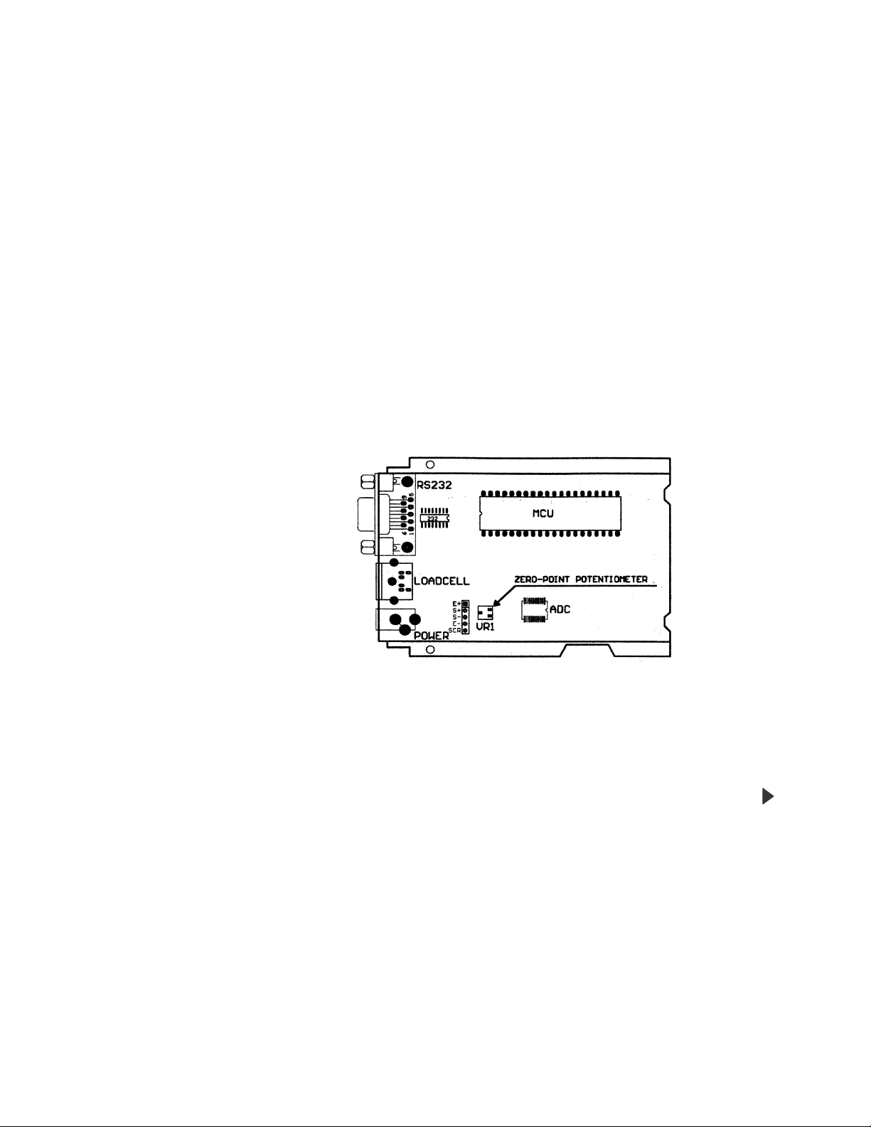
factory-calibrated and adjustment is not necessary. Refer to Figure 5.1 for the
zero point potentiometer location. Decrease ADC data by rotating clockwise,
and increase ADC data by rotating counter-clockwise.
Figure 5.1 Zero Point Potentiometer Location
3. Press the [UNIT] key to select the ADC weight inner code or input the inner
working voltage value. When Ux.xx is displayed, the displayed digits are the
voltage value. The proper working power voltage is between 5V - 8V.
4. Press the [TARE] key to display filtered or unfiltered weigh A/D data. When
is on the data is filtered.
5. Press the [ON/OFF/ZERO] key to exit this mode and return to the normal
weighing mode.
MS140/300 User Instructions 27
Page 30
6 Serial Communication
6.1 Com Port 1
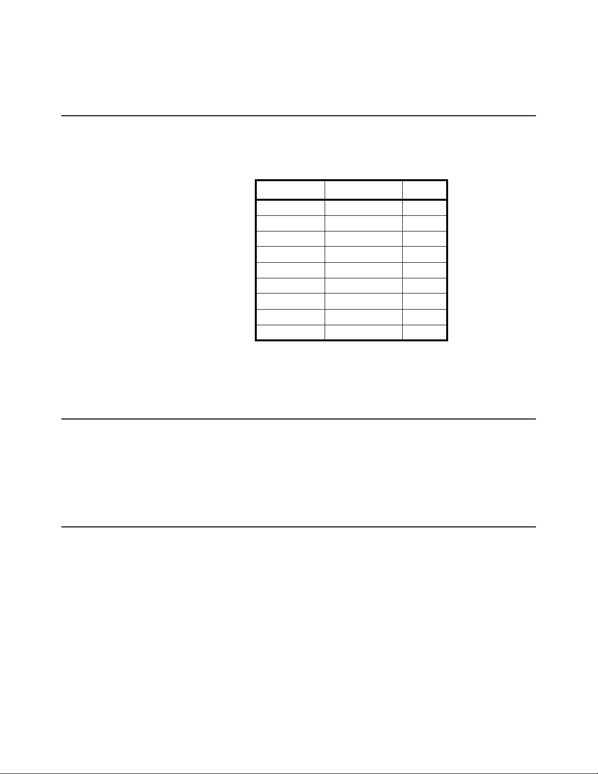
COM1 is a RS-232 bi-directional port. Communication wires are connected to the RS232 connector using TXD1, RXD1 and GND.
Table 6.1 PS-500 Com1 Port
Designation Description Pin
TXD transmit 2
RXD receive 3
GND ground/common 5
DSR data set ready 4
DTR data terminal ready 6
CTS clear to send 7
RTS return to send 8
no connection no connection 1
no connection no connection 9
NOTE: The indicator DB9 female connector has pin 4 and pin 6 shorted together.
Pin 7 and pin 8 are also shorted together.
6.2 Protocol
The baud rate and byte format is fixed by P5 and P6 settings.
Responses to serial commands will be immediate or within one weight measure cycle
of the scale. One second should be adequate for use as a time-out value by remote
(controlling) device.
6.3 Transaction String
The length of the weight field will be 7 digits. One digit for minus sign, one for decimal
point, 2 for unit of measure.
l If the unit is lb:oz, another two for lb and on for a space after lb. Units of
measure abbreviations are always lower case.
l If the weight is over capacity, the scale will return nine "^" characters (the
field of minus sign, decimal point, weight data is filled by "^").
l If the weight is under capacity, it will return nine "_" characters (the field of
minus sign, decimal point, and weight data is filled by "_").
l If the zero point is error, it will return nine "_" characters. The character will
be “-” for negative weight or a space character for positive weight. Minus
sign follow after the first digit.
Useless leading 0 before digits is suppressed.
28 MS140/300 User Instructions
Page 31
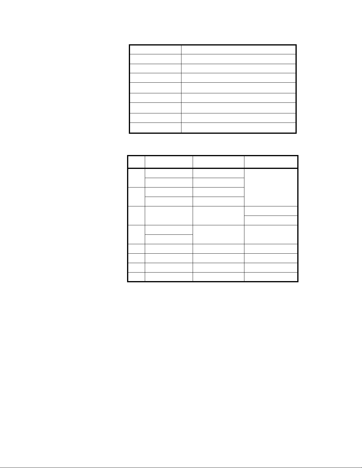
Table 6.2 Symbols Used
<LF> Line Feed character (hex 0AH)
<CR> Carriage Return character (hex 0DH)
<ETX> End of Text character (hex 03H)
<SP> Space (hex 20H)
H
1H2H3
Four current status bytes
<P> Polarity character: "?" or " "
---W
W
1
7
Reading data, 1-7 bytes (seven digits)
<DP> Decimal point
U
1U2
Measure units, kg, lb, lb:oz, % or pcs; 2-5 bytes
Bit
Table 6.3 Bit Definition of H
Byte 1 (H
) Byte 2 (H2) Byte 3 (H3)
1
1H2H3
0 0 = stable 0 = not under capacity 00 = compare disable
1 = not stable 1 = under capacity
1 0 = not at zero point 0 = not over capacity
01 = lower limit
10 = ok
11= upper limit
1 = at zero point 1 = over capacity
2 always 0 always 0 0 = gross weight
1 = net weight
3 0 = eeprom OK always 0 always 0
1 = eeprom error
4 always 1 always 1 always 1
5 always 1 always 1 always 1
6 always 0 always 1 always 0
7 parity parity parity
MS140/300 User Instructions 29
Page 32
6.4 Commands and Response
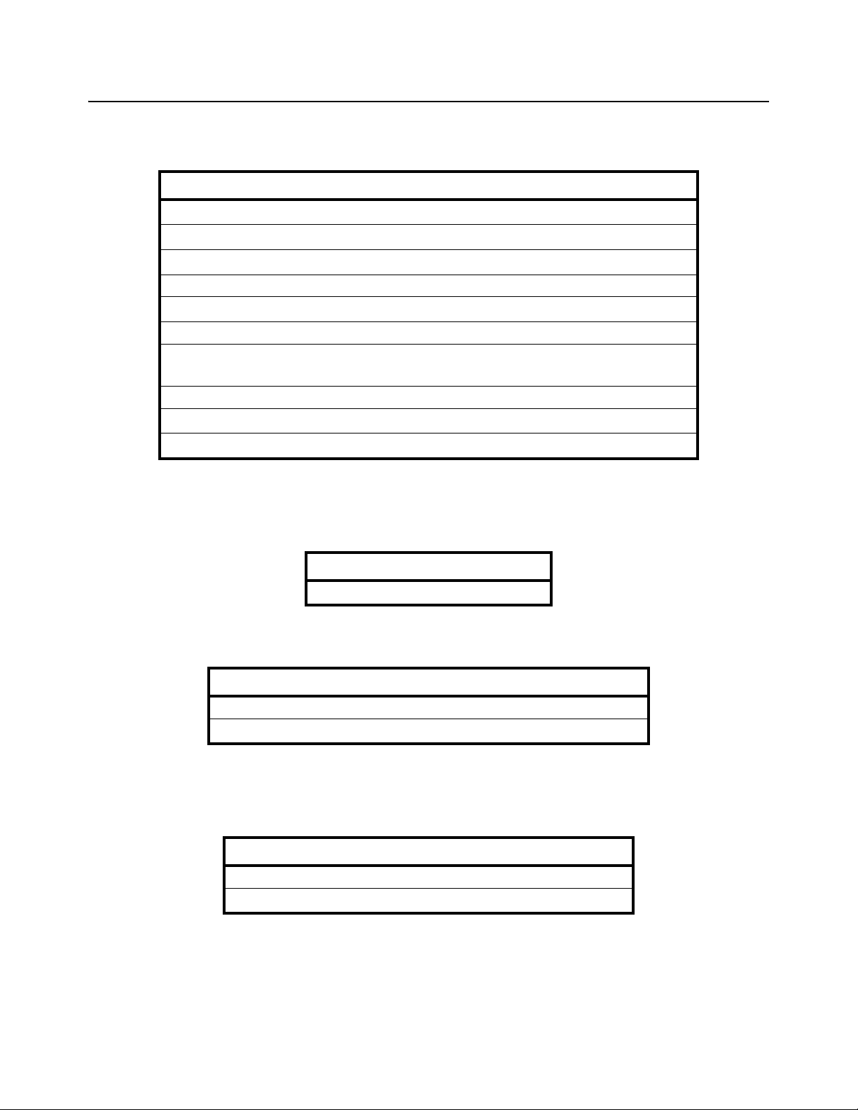
Command: W<CR> (57h 0dh), request current reading
Response
<LF>^^^^^^^^U
<LF>_ _ _ _ _ _ _ _ U
<LF> - - - - - - - - U
Note: If the weigh unit is lb:oz, U
<LF><P>W
<CR><LF> H1H2H3 <CR><ETX>---over capacity
1U2
<CR><LF> H1H2H3 <CR><ETX>---under capacity
1U2
<CR><LF> H1H2H3 <CR><ETX>---zero-point error
1U2
oz in above responses
1U2
1W2W3W4W5W6
<DP>W7 U1U2<CR><LF> H1H2H3 <CR><ETX>---scale is stable and the
current weigh unit is kg or lb. With or without decimal point and the position is as per the P9 setting.
<LF><P>W
<LF><P>W
lb<SP>W4W5lb<SP>W6W7oz<CR> H1H2H3<CR><ETX>
1W2W3
lb<SP>W4lb<SP>W5W6<DP>W7oz<CR> H1H2H3<CR><ETX>
1W2W3
Command: S<CR> (53h 0dh), request current status
Response
<LF> H
1H2H3
<CR><ETX>
Command: Z<CR> (5ah 0dh)
Response
Zero function is activated (simulate ZERO key) and it returns to current scale status.
<LF> H
1H2H3
<CR><ETX>
If ZERO function cannot be activated, it will return to current scale status.
Command: T<CR> (54h 0dh)
Response
TARE function is activated (simulate TARE key), and then returns scale status.
<LF> H
If TARE function cannot be activated, it will return to current scale status.
1H2H3
<CR><ETX>
30 MS140/300 User Instructions
Page 33
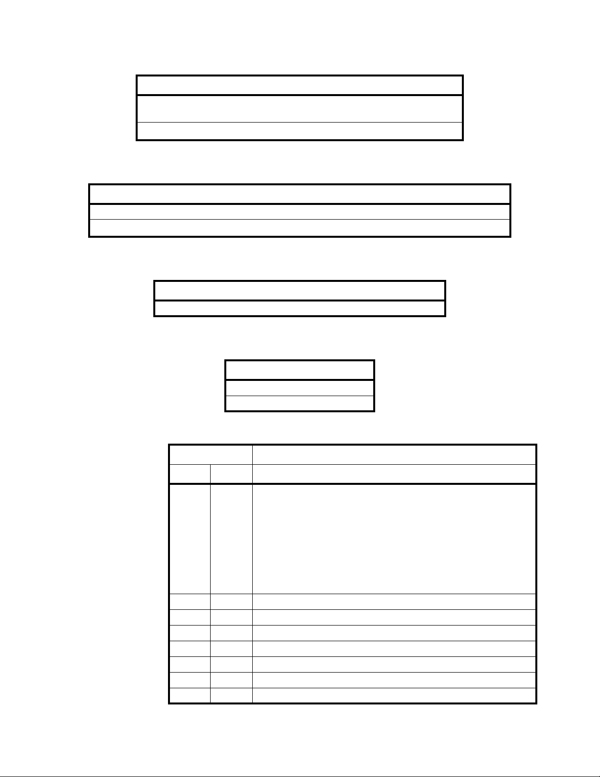
Command: U<CR> (55h 0dh)
Response
Changes units of measure (simulate UNIT key) and return scale status with new units,
The new measure unit should be allowed to use
<LF> U
<CR><LF> H1H2H3<CR><ETX>
1U2
Command: L<CR> (4ch 0dh)
Response
If Hold function can be activated, it will enable/disable hold function (simulate HOLD key) and returns scale status.
<LF> H
1H2H3
<CR><ETX>
Command: X<CR> (58h 0dh)
Response
Power off the scale, just like press down the ON/OFF key to turn off the scale.
Command: all others
Response
Unrecognized command
<LF>? <CR><ETX>
Table 6.4 Summary of Command and Response:
Command Response
ASCII HEX
W<CR> 57 0d Read scale weight:
<LF>^^^^^^^^U1U2 U3U4U5<CR><LF> H1H2H3 H4<CR><ETX>---over
capacity
?<LF>________U1U2U3U4U5<CR><LF> H1H2H3 H4<CR><ETX>---under
capacity
?<LF>-------- U1U2 U3 U4U5<CR><LF> H1H2H3 H4<CR><ETX>---zero-point
error
?<LF><p>W1W2W3W4W5<dp>W6U1U2U3U4U5<CR><LF>H1H2H3H4<CR
><ETX>---normal data
S<CR> 53 0d <LF> H1H2H3H4<CR><ETX>; read scale status
Z<CR> 5a 0d <LF> H1H2H3H4<CR><ETX>; simulate ZERO key
T<CR> 54 0d <LF> H1H2H3H4<CR><ETX>; simulate TARE key
U<CR> 55 0d <LF> U1U2 U3 U4U5<CR><LF> H1H2H3H4<CR><ETX>; simulate UNIT key
L<CR> 4c 0d <LF> H1H2H3H4<CR><ETX>; simulate HOLD key
X<CR> 58 0d power off the scale, simulate OFF key
others <LF>? <CR><ETX>
MS140/300 User Instructions 31
Page 34
7 Troubleshooting
This chapter gives explanations on commonly seen errors, display characters and
display symbols.
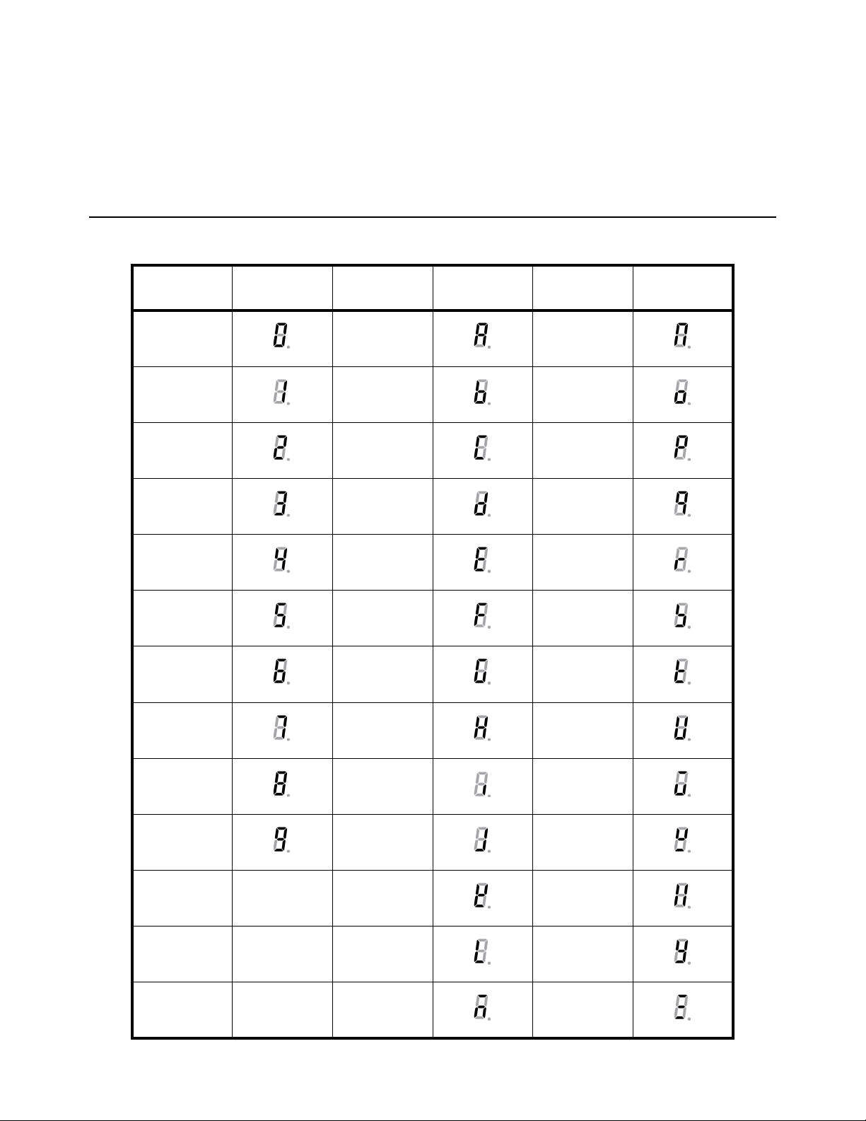
7.1 Display Characters
ASCII
0AN
1BO
2CP
3DQ
4ER
5FS
6GT
Display
Character
ASCII
Display
Character
ASCII
Display
Character
7HU
8IV
9JW
KX
LY
MZ
MS140/300 User Instructions 32
Page 35
7.2 Display Symbols
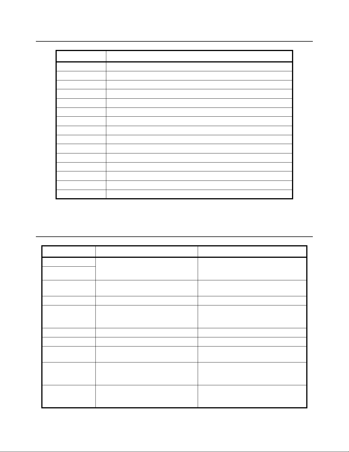
Symbol Description
0------ Zero is over the setting range
0_______ Zero point is below the setting range
Ad------ Signal to ADC is over maximum range
Ad______ Signal to ADC is below minimum range
-------- Weight is over upper limitation or display data is over limitation
________ Weight is below lower limitation
eep.e0 EEPROM can’t be accessed.
EEP.E1 The parameters are not the same as the backup data
EEP.E2 The setting parameter(s) is not in normal range
Lo.bAt Battery voltage is below 4.7V
CAP.- - The setting full capacity will be displayed
CAL.Px Calibration on point (x)
CAL.Er Calibration error, maybe input data or loaded weight is incorrect, unstable, non-linear
d.-- The division will be displayed
px.y The x = parameter, y = parameter choice
7.3 Error Messages and Troubleshooting
Symptom Probable Cause Remedy
Ad------ Loadcell wires to indicator are incorrectly
Ad______
0------ Weight reading exceeds Power On Zero limit. Make sure scale platform is empty. Perform zero
0______ Weight reading below Power On Zero limit. Install platform on scale. Perform zero calibration.
-------- Weight reading exceeds Overload limit or the
________ Weight reading below under load limit. Install platform on scale. Perform zero calibration.
EEP.E2 Parameter is not correctly set. Re-set parameter
CAL.Er Calibration error. Input data or loaded weight is
Will not turn on. Power cord not plugged in or properly
Cannot zero the display
or will not zero when
turned on.
connected, shorted, opened, ADC or loadcell(s)
are damaged.
weight value cannot be displayed in the current
unit of measure because it exceeds 6 digits.
too small, too big, unstable, non-linear.
connected. Power outlet not supplying
electricity. Battery discharged. Other failure.
Load on scale exceeds allowable limits. Load
on scale is not stable. Load cell damage.
Make sure wires are ok and correctly connected.
Replace loadcell or ADC chip, Service required.
calibration.
Reduce load on scale until weight value can be
displayed. Use a more appropriate unit of measure.
Input correct data, load correct weight onto
platform, Service required.
Check power cord connections. Make sure power
cord is plugged into the power outlet. Check power
source. Replace batteries. Service required.
Remove load on scale. Wait for load to become
stable. Service required.
33 MS140/300 User Instructions
Page 36

Page 37

Brecknell USA
1000 Armstrong Dr.
Fairmont MN 56031
Tel:507-238-8702
Fax:507-238-8271
Email: [email protected]
http://www.brecknellscales.com
Brecknell UK
Foundry Lane,
Smethwick, West Midlands,
England B66 2LP
Tel:+44 (0) 8452 46 6717
Fax:+44 (0) 8452 46 6718
Email:
[email protected]
http://www.brecknellscales.com
Page 38
MS140/300
Balance électronique médicale portable à rampe
Mode d’emploi
AWT35-501200 Numéro AA Juin 2013
Page 39

© Brecknell, s.e.c. 2013. Tous droits réservés.
Le présent document ne peut être, en tout ou en partie, reproduit, enregistré dans un système d’extraction
électronique, ou transmis de quelque manière ou sous quelque forme que ce soit, électroniquement,
mécaniquement, par photocopie, enregistrement ou autre, sans le consentement écrit préalable du détenteur du
droit d'auteur, sous réserve des dispositions d’une loi ou d’une licence. La source doit être totalement reconnue.
Brecknell est une marque de commerce déposée de Brecknell, s.e.c. La présente publication était correcte au
moment de mettre sous presse, mais Brecknell, s.e.c. se réserve le droit de modifier, sans préavis, les devis,
conception, prix ou modalités de prestation de tout produit ou service à tout moment.
Toutes les marques et noms de produits externes utilisés aux présentes sont des marques de commerce ou
marques déposées de leurs propriétaires respectifs.
MS140_300 Portable Medical Scale_u_en_501200.book
Page 40

Table des matières
Chapitre 1 Renseignements et avertissements généraux ..................................................................... 3
À propos de ce manuel ......................................................................................................3
Conventions d’écriture .................................................................................................3
Messages spéciaux .....................................................................................................3
Avertissements ..................................................................................................................4
Conformité aux EMC ....................... ... ....................................... ... .... ..................................4
Entretien de routine ............................................................................................................5
Nettoyer l’indicateur ...........................................................................................................5
Objets pointus ....... .... ... ....................................... ... ... ... ....................................... ... ... .........5
Chapitre 2 Caractéristiques ...................................................................................................................... 6
Plateforme de la balance ...................................................................................................6
Capacité ......................................................................................................................6
Précision ................................... ....................... ...................... ....................... ...............6
Dimensions ...................................... ...................... ....................... ...................... .........6
Indicateur de balance ...................................... .... ...................................... .... ... ... ... ... .... ... ..6
Alimentation ..................................... ...................... ....................... ...................... .........6
Dimensions ...................................... ...................... ....................... ...................... .........6
Affichage .....................................................................................................................7
Clavier .........................................................................................................................7
Environnement ...........................................................................................................7
Activation de la cellule de pesée .................................................................................7
Communication ...........................................................................................................7
Chapitre 3 Introduction ............................................................................................................................. 8
Montage de l’indicateur ......................................................................................................8
Panneau avant ...................................................................................................................8
Affichage ................................... ................................................................ .........................9
Clavier ....................................... ................................... .................................... ................10
Parcourir le mode de pesée ........ ... ... .... ... ... ....................................... ... ... .... ... ... ... ... .... ... 11
Allumer le témoin .......................................................................................................11
Entrer ou quitter le mode HOLD (RETENIR) ...................... .......................... .............11
Zéro ...........................................................................................................................11
Tare ...........................................................................................................................11
Supprimer le poids à vide ..........................................................................................11
Données de sortie (Print) (Imprimer) .................. ....................................................... 12
Modifier l’unité de pesée ...........................................................................................12
Fonction Hold (Retenir) ....................................................................................................14
Accès au mode Hold (Retenir) ..................................................................................14
Chapitre 4 Mode de configuration ...................................................................... .......................... ..........15
Entrer dans le menu de configuration ..............................................................................15
Parcourir le menu Setup (Configuration) .................................................................. .... ... 15
Paramètres du menu de configuration ...................................... .................................... ...16
Relation de capacité et paramètres P7, P8 et P9 ............................................... ... ... .... ... 21
Quitter le menu Setup (Configuration) .............................................................................24
Chapitre 5 Calibration ............................................................................................................................. 25
Mode de calibrage ........................................................................................................ ... 25
Afficher le code ADC ou la valeur de tension active ........................................................26
Mode d’emploi du MS140/300 1
Page 41

Chapitre 6 Communications de série ....................................................................................................28
Port Com 1 ...... ....................................... ... ... ....................................... ... ... .......................28
Protocole ...................................... .................................... ................................... .............28
Séquence de transaction ................................................................................................. 28
Commandes et réponses .................................................................................................30
Chapitre 7 Dépannage ...................................................... .................................................... ................... 32
Caractères d’affichage ....... .... ... ....................................... ... ... ... ... .... ... ... ... .... ... ................32
Symboles affichés ............................................................................................................ 33
Messages d’erreur et dépannage ....................................................................................33
2 Mode d’emploi du MS140/300
Page 42
1 Renseignements et avertissements généraux
1.1 À propos de ce manuel
Il est divisé en chapitres; chaque chapitre est numéroté et est identifié par les gros
caractères en haut de page. Les subdivisions sont identifiées tel qu’indiqué par les
entêtes 1 et 1.1 indiquées ci-dessus. Le nom du chapitre et le niveau de subdivision
suivant sont indiqués en haut de page, à toutes les deux page s du manuel, pour vous
rappeler où vous êtes, dans celui-ci. Le nom du manuel et le numéro de la page sont
indiqués en bas de page.
1.1.1 Conventions d’écriture
Les touches utilisées pour interagir avec le PS-500 sont situées sur le clavier de
l'affichage. Les touches à activer sont indiquées en caractères GRAS entre
parenthèses. (p. ex., [ZERO])
Les messages affichés sont indiqués en format ACL (p. ex., setUp
(CONFIGURATION)) et reflètent la casse du message affiché.
1.1.2 Messages spéciaux
Vous trouvere z ci-après des exemples de messages particuliers que vous rencontrerez
dans ce manuel. Les mots-clés portent un sens particulier pour vous avertir qu’il y a
d’autres renseignements ou du niveau relatif du danger.
ATTENTION!
Ceci est un symbole de prudence (Attention).
Les messages de type Attention fournissent des renseignements sur les
processus qui, s’ils ne sont pas suivis, peuvent causer des dommages
matériels ou la corruption et la perte de données.
DANGER ÉLECTRIQUE!
CECI EST UN SYMBOLE DE DANGER ÉLECTRIQUE.
LE DANGER ÉLECTRIQUE INDIQUE QUE SI VOUS OMETTEZ DE
RESPECTER CERTAINES MÉTHODES OU PROCESSUS, VOUS VOUS
EXPOSEZ À UN RISQUE D’ÉLECTROCUTION, DE BRÛLURE PAR ARC,
D’EXPLOSION OU AUTRES DANGERS QUI PEUVENT CAUSER DES
BLESSURES OU LA MORT.
NOTA : Ceci est un symbole de Nota. Les notes (Nota) fournissent des
renseignements importants et des astuces qui vous aident à vous servir du produit.
Mode d’emploi du MS140/300 3
Page 43
1.2 Avertissements
l Veuillez lire attentivement l’ensemble du mode d’emploi avant de vous en
l Éviter l'exposition prolongée à la chaleur ou au froid extrême. Votre balance
l Prévoir un réchauffement adéquat. Allumer la balance et attendre quelques
l Ces balances électroniques sont des instruments de précision. Ne pas
l Éviter de vous en servir dans un environnement à fortes vibrations et à forts
l Lire le poids rapidement après avoir posé la charge sur la balance. Le
servir.
fonctionne mieux à la température ambiante normale. Toujours permettre à
la balance de s’habituer à la température ambiante avant de vous en servir.
minutes, dans la mesure du possible. Ça permettra aux éléments internes
de se stabiliser avant de calculer des poids.
utiliser près d’un téléphone cellulaire, d’une radio, d’un ordinateur ou de tout
appareil électronique. Ces appareils émettent des radiofréquences qui
peuvent brouiller la lecture de la balance.
courants d'air.
résultat de la cellule de mémoire et des emplacements A à D peuvent être
un peu influencés après avoir laissé un poids sur la balance pendant une
période prolongée.
DANGER: POUR VOTRE PROTECTION, TOUS LES PRINCIPAUX
APPAREILS (110 V OU 230 V) UTILISÉS DANS DES CONDITIONS
HUMIDES OU MOUILLÉES DOIVENT ÊTRE BRANCHÉS À UNE
SOURCE AVEC SYSTÈME D’ARRÊT DE CALIBRE IDOINE ET
PROTÉGÉS PAR UN DISPOSITIF DE PROTECTION CONTRE LE
DÉFAUT DE SOL APPROUVÉ (RCD, GFCI, ETC.).
DANGER: RISQUE D’ÉLECTROCUTION. ASSUREZ-VOUS DE
DÉBRANCHER L’INDICATEUR AVANT DE RETIRER LE COUVERCLE
OU D’OUVRIR L’APPAREIL. CONFIER L’ENTRETIEN À UNE
PERSONNE COMPÉTENTE.
1.3 Conformité aux EMC
L’avertissement suivant peut concerner votre appareil.
ATTENTION!
Ceci est un produit de catégorie A.
Dans un environnement domestique, ce produit peut créer des interférences
radio qui peuvent obliger l'utilisateur à prendre des dispositions idoines.
4 Mode d’emploi du MS140/300
Page 44
États-Unis
Cet équipement a été testé et déclaré conforme aux restrictions des appareils
numériques de catégorie A, conformément à la section 15 des règles de la FCC. Ces
restrictions sont conçues pour of frir une protection raisonnable contre les interférences
nocives lorsque l’équipement est utilisé dans un environnement commercial. Cet
équipement génère, utilise et peut émettre de l’énergie des fréquences radio et, s’il
n’est pas installé et utilisé conformément au manuel d’instruction, peut causer des
interférences dommageables aux radiocommunications. L’utilisation de cet
équipement dans un lieu résidentiel est susceptible de provoquer une interférence
dommageable auquel cas l’utilisateur devra corriger l’interférence à ses frais.
Canada
Le présent appareil numérique n’émet pas de bruits radioélectriques dépassant les
limites applicables aux appareils numériques de la Classe A prescrites dans le
Règlement sur le brouillage radioélectrique edicté par le mi nistère des
Communications du Canada.
1.4 Entretien de routine
IMPORTANT : Cet équipement doit faire l’objet d’une vérification de routine de
son fonctionnement et de son calibrage.
L ’applica tion et l’utilisation déte rmineront la fréq uence de calibr age nécess aire
à une utilisation sécuritaire.
Toujours éteindre la machine et l’isoler de l’alimentation en énergie avant
d’entreprendre l’entretien de routine afin d’éviter la possibilité d’électrocution.
1.5 Nettoyer l’indicateur
Table 1.1 Choses À FAIRE et À NE PAS FAIRE en ce qui a trait au nettoyage
À FAIRE À NE PAS FAIRE
Essuyer l’extérieur des produits standards
avec un linge propre, humecté d’eau et
d’une petite quantité de détergent doux
Vaporiser le linge lors de l’utilisation d’un
liquide de nettoyage
Tenter de nettoyer l’intérieur de l’indicateur
Employer des abrasifs durs, des solvants, des récurants
ou des solutions de nettoyage alcalines
Vaporiser tout liquide directement sur la fenêtre
d’affichage
1.6 Objets pointus
Ne pas utiliser d’objets pointus comme un tournevis ou des ongle s lon gs pour activer
les touches.
Mode d’emploi du MS140/300 5
Page 45

2 Caractéristiques
2.1 Plateforme de la balance
2.1.1 Capacité
l 300 kg x 0,1 kg
l 660 lb x 0,2 lb
l 660 lb x 5 oz
2.1.2 Précision
l ± 3 divisions (0,3 kg, 0,6 lb, 15 oz)
2.1.3 Dimensions
l 520 mm (L) x 520 mm (L) x 65 mm (H)
m 20,5 po. L x 20,5 po. L x 2,5 po. H
2.2 Indicateur de balance
l Intervalle du signal d’entrée : 0–30 mV
l Sensibilité : >0,2 µV/grad
l Résolution interne : Environ 520 000 comptes
l Résolution d’affichage : choix possibles entre 500 et 100 000
l Linéarité du système : moins de 0,01 % de la capacité
l Méthode de calibrage : Calibrage logiciel avec entreposage à long terme
dans EEPROM
2.2.1 Alimentation
l Batteries alcalines : 4 batteries AAA (autonomie de 20 heures)
l Adaptateur CA : 6 VDC, 500 mA avec négatif central
l Courant de fonctionnement : 0,25 mA
m (lorsque la tension est de 5-8 Vdc sans tenir compte de la
consommation du capteur de charge)
2.2.2 Dimensions
l 164 mm (L) x 762 mm (L) x 64 mm (H)
m 6,5 po L x 3,2 po H x 1,2 po L
6 Mode d’emploi du MS140/300
Page 46
2.2.3 Affichage
l ACL 5 chiffres, 7 segments, 16 mm (0,625 po.)
2.2.4 Clavier
l 4 touches à pression
2.2.5 Environnement
Température de fonctionnement De 5 ° à 35 °C
Température d’entreposage De -10 °C à 70 °C
Humidité ≤ 95 % RH sans condensation
2.2.6 Activation de la cellule de pesée
Comme plus d’une cellule de pesée peut être utilisée sur une balance, voici les
exigences pour l’utilisation d’un ensemble de cellules.
Tension 4,4 VDC
Courant maximal 55 mA (peut alimenter des cellules de pesée de 4 à 350 ohm)
Branchement du signal 4 ou 6 signaux avec signal de détection
Sensibilité maximale 0,3 mV/V à +3 mV/V (doit convenir à un calibre d'affichage de >0,2 µV)
Résisteur d’entrée ≥80 Ω
Résisteur de sortie <10 KΩ
2.2.7 Communication
Mode Il est possible de choisir entre le mode duplex total ou sortie seule
Vitesse de transfert Modifiable : 1200-2400-4800-9600-19200 bps
Format des données 7 bits données, parité paire ou impaire, 1 bit d’arrêt
8 bits données, sans parité, 1 bit d’arrêt
Protocole 7 protocoles choisis (un compatible à la norme NCI SCP-01)
Données de sortie poids brut, poids net, poids à vide, indicateur affichant le poids, unité de pesée, etc.
Mode d’emploi du MS140/300 7
Page 47
3 Introduction
d=Max
ZERO
NET
lb
kg
oz
Ce chapitre présente le montage de l’indicateur, l’affichage et le fonctionnement du
clavier en mode de pesée normale.
3.1 Montage de l’indicateur
Le PS-500 est fourni avec une pince de plastique ABS. Monter verticalement au mur
ou horizontalement sur un support selon vos besoins.
3.2 Panneau avant
Le clavier incorpore l’affichage et le clavier.
8 Mode d’emploi du MS140/300
Page 48
3.3 Affichage
Max
d=
lb
kg
oz
Symbole affiché Description
ZERO La balance est au point zéro et le poids brut est à 0.
L'indicateur du PS-500 utilise un ACL (affichage à cristaux liquides) à 7 segments
affichant le poids et des données système.
Les flèches s’illumineront pour indiquer le mode en cours..
Figure 3.1 Affichage du PS-500
Table 3.1 Voyants d’affichage ACL et définitions
HOLD (RETENIR) La balance est en mode HOLD (RETENIR).
Le poids actuel est affiché lorsque la flèche clignote. Le poids actuel est verrouillé lorsque la
flèche ne clignote pas.
NET Indique le fonctionnement en mode net et que le poids à vide n'est pas de 0.
lb Indique que l’unité de mesure actuelle est la livre.
oz Indique que l’unité de mesure actuelle est l’once.
kg Indique que l’unité de mesure actuelle est le kilogramme.
Mode d’emploi du MS140/300 9
Page 49
3.4 Clavier
Touche Fonction
Le clavier est constitué de quatre touches dont certaines ont plus d'une fonction.
Figure 3.2 Clavier SBI-521
Table 3.2 Fonctions des touches (Mode de fonctionnement normal)
Si cette touche n’est définie que pour le mode HOLD (RETENIR) (P2=0), appuyer pour
entrer ou quitter le mode HOLD (RETENIR).
Si cette touche n’est définie que pour le mode PRINT (IMPRIMER) (P2=1), appuyer
pour exporter les données selon le paramètre P4.
Si cette touche n’est définie que pour le mode HOLD et PRINT (RETENIR et
IMPRIMER) (P2=2), appuyer pour exporter les données selon le paramètre P4 et
conserver le poids actuel.
Choisir les unités de poids; lb, kg, lb:oz
Nota : Les unités de poids utilisables sont déterminées par division de l’affichage et par
l’unité de mesure de poids de calibrage (restreint par P8, P9 et P10)
Par exemple, si l’unité de calibrage est le kilogramme, la résolution d’affichage du
calibrage est de 50 kg (donc : P8=5, P9=0, P10=0). Si la touche UNIT (UNITÉ) est
appuyée pour choisir l’unité de pesée, lb ou lb:oz ne sont pas disponibles car la
résolution d’affichage de 100 lb ou 2 000 oz n’est pas disponible pour cet indicateur.
Fonction de tare
Cette fonction peut être activée uniquement lorsque la balance est en mode stable et
que le poids brut n'est pas négatif.
Marche
Fonction zéro : Lorsque le poids est dans l’intervalle du zéro, la fonction ZERO (ZÉRO)
s’activera et supprimera le poids à vide. Lorsque le poids n’est pas dans l’intervalle du
zéro (P13), la balance indiquera 0----- (le point zéro est au-dessus de l’intervalle de
calibrage) ou 0_____ (le point zéro est sous l'intervalle de calibrage).
L’arrêt
Ignore les modifications
Préparez-vous à quitter le mode d’utilisation actuel
10 Mode d’emploi du MS140/300
Page 50
3.5 Parcourir le mode de pesée
3.5.1 Allumer le témoin
Allumer ou éteindre le témoin avec la touche [ON/OFF].
3.5.2 Entrer ou quitter le mode HOLD (RETENIR)
Appuyer sur la touche [HOLD] (RETENIR).
3.5.3 Zéro
Lorsque le poids est stable et dans l' intervalle du zéro, appu yez sur la to uche [ZERO]
pour fixer un nouveau point zéro. Pour connaître les restrictions quant au tarage,
consulter Table 3.3.
3.5.4 Tare
Lorsque le poids brut est supérieur à zéro et que la bala nce est st able, appuyer su r la
touche [TARE] (TARE) . L’indicateur affichera un poids net de zéro et la flèche à droite
du mot « NET » sera illuminée. Pour connaître les restrictions quant au tarage,
consulter Table 3.3.
3.5.5 Supprimer le poids à vide
Retirer tout poids sur le plateau et attendre que la balance se stabilise. Appuyer sur la
touche [TARE] (TARE).
Standard
É.-U. ≤0 non Aucune action Zéro
Canada ≤0 non Aucune action Zéro
Poids sur
le plateau
>0 non Tare
>0 non Tare
Table 3.3 Limites de zéro et de tare
Données dans
l’unité de mémoire
TARE (TARE)
oui Supprimer le poids à vide
oui
oui Supprimer le poids à vide
oui Aucune action
principales fonctions
Touche de tare Touche zéro
Mode d’emploi du MS140/300 11
Page 51
Standard
Europe ≤0 non Aucune action Zéro
Aucun
(identique à
l’Europe)
Poids sur
le plateau
>0 non Tare Zéro
≤0 non Aucune action Zéro
>0 non Tare Zéro
Données dans
l’unité de mémoire
TARE (TARE)
oui Supprimer le poids à vide Annuler et supprimer
oui Annuler et supprimer
oui Supprimer le poids à vide Annuler et supprimer
oui Annuler et supprimer
3.5.6 Données de sortie (Print) (Imprimer)
Lorsque la balance est stable, appuyer sur la touche [PRINT] (IMPRIMER).
principales fonctions
Touche de tare Touche zéro
le poids à vide
le poids à vide
le poids à vide
le poids à vide
3.5.7 Modifier l’unité de pesée
Appuyer sur la touche [UNIT] (UNITÉ) pour choisir kg, lb ou lb:oz. Nota : le choix lb:oz
n’est pas toujours offert. Veuillez consulter les tableaux suivants.
Table 3.4 Utiliser le kilogramme comme unité de base
Valeur de division
du calibrage
0,0001 kg 0,0001 kg 0,0002 lb Non disponible
0,001 kg 0,001 kg 0,001 lb Non disponible
0,01 kg 0,01 kg 0,01 lb 0,5 oz
0,1 kg 0,1 kg 0,09 lb Non disponible
1 kg 1 kg 2 lb Non disponible
10 kg 10 kg 20 lb Non disponible
0,0002 kg 0,0002 kg 0,0005 lb Non disponible
0,002 kg 0,002 kg 0,005 lb 0,1 oz
0,02 kg 0,02 kg 0,05 lb 1 oz
0,2 kg 0,2 kg 0,5 lb Non disponible
2 kg 2 kg 5 lb Non disponible
20 kg 20 kg 50 lb Non disponible
0,0005 kg 0,0005 kg 0,001 lb Non disponible
Afficher la valeur de division
kg lb lb:oz
12 Mode d’emploi du MS140/300
Page 52
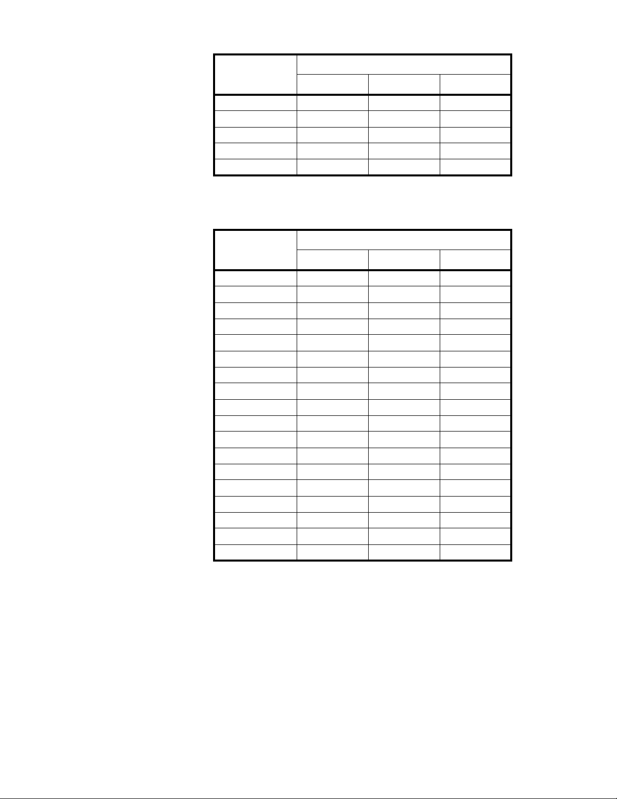
Valeur de division
du calibrage
Afficher la valeur de division
kg lb lb:oz
0,005 kg 0,005 kg 0,01 lb 0,2 oz
0,05 kg 0,05 kg 0,1 lb 2 oz
0,5 kg 0,5 kg 1 lb Non disponible
5 kg 5 kg 10 lb Non disponible
50 kg 50 kg Non disponible Non disponible
Table 3.5 Utiliser la livre comme unité de base
Valeur de division
du calibrage
Afficher la valeur de division
kg lb lb:oz
0,0001 lb Non disponible 0,0001 lb Non disponible
0,001 lb 0,0005 kg 0,001 lb Non disponible
0,01 lb 0,005 kg 0,01 lb 0,2 oz
0,1 lb 0,05 kg 0,1 lb 2 oz
1 lb 0,5 kg 1 lb Non disponible
10 lb 5 kg 10 lb Non disponible
0,0002 kg 0,0001 kg 0,0002 kg Non disponible
0,002 lb 0,001 kg 0,002 lb Non disponible
0,02 lb 0,01 kg 0,02 lb 0,5 oz
0,2 lb 0,1 kg 0,2 lb Non disponible
2 lb 1 kg 2 lb Non disponible
20 lb 10 kg 20 lb Non disponible
0,0005 lb 0,0002 kg 0,0005 lb Non disponible
0,005 lb 0,002 kg 0,005 lb 0,1 oz
0,05 lb 0,02 kg 0,05 lb 1 oz
0,5 lb 0,2 kg 0,5 lb Non disponible
5 lb 2 kg 5 lb Non disponible
50 lb 20 kg 50 lb Non disponible
Mode d’emploi du MS140/300 13
Page 53

3.6 Fonction Hold (Retenir)
La fonction HOLD (RETENIR) peut servir à bloquer un nom bre affiché. Dans ce mode,
la balance peut capturer une variable, une constan te, ou la moyenne d'une var iable et
mettre ce chiffre en mode HOLD (RETENIR) temporairement pour permettre à
l’utilisateur de le consulter ou de l’enregistrer.
La fonction HOLD (RETENIR) peut être utilisée en mode de pesée normale, en mode
de comptage, et en mode de pourcentage de poids. Après être entré en mode HOLD
(RETENIR), il est possible d’accélérer la vitesse du convertisseur A-D à de 10 à 80 Hz
(si le paramètre USER-HOLD-AD.H SPD est réglé à YES (OUI)) pour certaines
activités de pesée dynamique.
Il est possible de peser des échantillons de pesée animés, comme des animaux
vivants ou des objets en déplacement à l’aide de la fonction de retenue. Le témoin offre
des paramètres de mode spécial pour accommoder les mouvement s de charge.
3.6.1 Accès au mode Hold (Retenir)
Pour entrer en mode HOLD (RETENIR), appuyer sur le bouton [HOLD] (RETENIR)
pendant que vous êtes en mode de pesée normale.
14 Mode d’emploi du MS140/300
Page 54
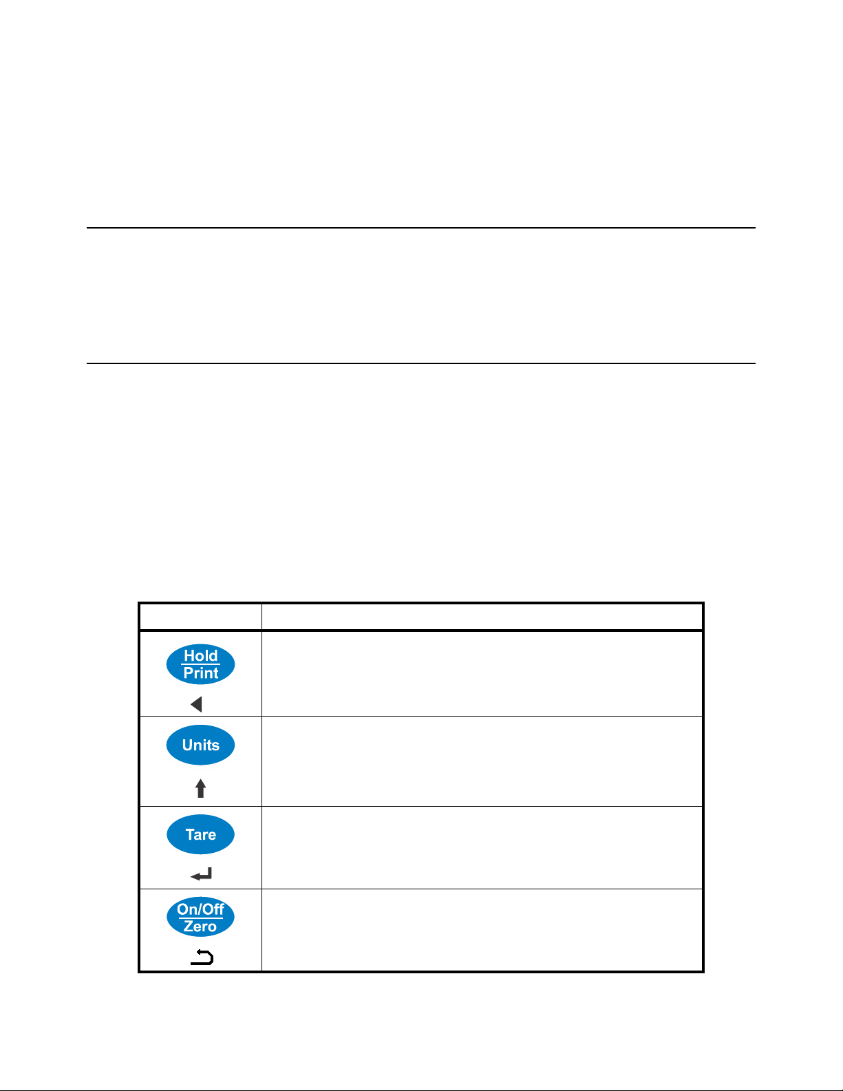
4 Mode de configuration
Afin de configurer l’indicateur, vous devez d'abord activer le mode approprié. Les
touches du clavier deviennent des flèches permettant de se déplacer dans les menu s.
Pour de plus amples renseignements, voir le Table 4.1.
4.1 Entrer dans le menu de configuration
1. Tenir enfoncée les touches [ON/OFF/ZERO] et [UNIT] (UNITÉ) jusqu’à ce que
SETUP (CONFIGURATION) soit affiché.
1a. Cet indicateur propose 19 paramètres différents.
4.2 Parcourir le menu Setup (Configuration)
1. Une fois que SETUP (CONFIGURATION) est affiché, utiliser la touche [UNIT]
(UNITÉ) pour modifier les chiffres clignotants et la touche [HOLD/PRINT]
(RETENIR/IMPRIMER) key pour changer de chiffre clignotant.
Le paramètre sera désigné dans le format suivant :
PN.x ou PNN.xx – P est le paramètre; N ou NN est le numéro de paramètre; x ou xx
est le choix du paramètre. Pour consulter la liste des paramètres et des options pour
chacun, consulter le Table 4.2.
2. Utiliser la touche [TARE] (TARE) pour confirmer l’entrée, sauvegarder les
données et passer au paramètre suivant.
Table 4.1 Principales fonctions en mode de configuration
Touche Fonction
Déplacer le curseur de droite à gauche.
Modifier le chiffre sélectionné (0–9).
Passer au paramètre suivant.
Confirmer la valeur du paramètre choisi.
Sortir du mode de configuration et entrer en mode de travail normal.
Mode d’emploi du MS140/300 15
Page 55
4.3 Paramètres du menu de configuration
La présente section décrit plus en détails les choix offerts dans le menu de
configuration.
Le tableau du menu présente les options et le paramètre par défaut en format
d'affichage ACL pour reprendre l'affichage réel.
Table 4.2 Choix de paramètre et explications
SubMenu1 Option Par défaut Description du paramètre Commentaire
P1 00-15 05
p2 0-2 2
p3 0-2 2
3-50
p4 0-7 2
Délai d’arrêt automatique 00 = fonction désactivée
01–15 = délai d’arrêt automatique en minutes. La balance
s’éteindra automatiquement après le délai prescrit s’il n’y a pas
de variation de poids.
Fonction de touche Hold
(Retenir)
Fonction de mode Hold
(Retenir)
Sortie des données
d’impression
0 = fonction HOLD (RETENIR) seulement
1 = fonction PRINT (IMPRIMER) seulement
2 = fonction HOLD et PRINT (RETENIR et IMPRIMER).
Appuyer rapidement pour imprimer et longtemps pour retenir.
0 = aucune fonction Hold (Retenir)
1 = retenir une lecture de poids plus important
2 = annule automatiquement la fonction de retenue lorsque le
poids est inférieur à 10d et retient automatiquement un
nouveau poids stable (plus de 10d)
3–50 = lecture immuable lorsque la différence est de moins de
±3–50d
0 = aucune fonction du RS232. Aucune transmission ou
réception de données.
1 = exprime les données d’affichage lorsque la touche PRINT
(IMPRIMER) est enfoncée et que la lecture de poids est stable.
<LF><lecture de poids, signe de lecture négative, point
décimal, unité ><CR><EXT>
2 = présente le poids brut, le poids à vide et le poids net ainsi
que l’unité de mesure lorsque la touche PRINT (IMRPIMER)
est enfoncée.
<LF><Brut : lecture de poids, signe de lecture négative, point
décimal, unité ><CR><EXT>
<Poids à vide : lecture de poids, point décimal,
unité ><CR><EXT>
<Net : lecture de poids, signe de lecture négative, point
décimal, unité ><CR><EXT>
3 = affiche continuellement la lecture du poids et l’unité. Il n’y
aura aucune réception de données. Format de sortie identique
au choix 1.
4 = exprime continuellement le poids brut, le poids à vide, le
poids net et l'unité de mesure. Il n’y aura aucune réception de
données. Formats de sortie identique au choix 2.
5 = affiche les données d’affichage et l’unité de pesée une fois
lorsque la balance est stable. Format de sortie identique au
choix 1.
6 = affiche le poids brut, le poids à vide, le poids net et l’unité
de mesure une fois lorsque la balance se stabilise. Formats de
sortie identique au choix 2.
7 = Affichage des données Bio-RS232, compatible avec la
norme NCI-SP1
16 Mode d’emploi du MS140/300
Page 56
SubMenu1 Option Par défaut Description du paramètre Commentaire
P5 0-4 3
p6 0-2 0
p7 00-31 9
P8 0-2 1
p9 0-5 1
p10 0-1 1
p11 0-6 6
p12 0-7 3
p13 0-7 2
p14 0-2 2
Vitesse de transfert du
RS-232
0 = 1 200 bps
1 = 2 400 bps
2 = 4 800 bps
3 = 9 600 bps
4 = 19 200 bps
Protocole RS-232 0 = 8NO
1 = 7O1
2 = 7E1
Choix de la résolution de la
Le Table 4.3 présente les choix de résolution et les valeurs.
balance
Format de division du
calibrage
Voir Table 4.4 et Table 4.5
0 = 1
1 = 2
2 = 5
Point décimal au calibrage Voir Table 4.4 et Table 4.5
0 = 1
1 = 0,1
2 = 0,01
3 = 0,001
4 = 0,0001
5 = 10
Unité de calibrage Voir Table 4.4 et Table 4.5
0 = kg
1 = lb
Unités de mesure activées 0 = kg seulement
1 = lb seulement
2 = lb:oz seulement
3 = kg ou lb
4 = kg ou lb:oz
5 = lb ou lb:oz
6 = kg, lb, ou lb:oz
Intervalle zéro au
démarrage
0 = calibrage du point zéro +1 %FS
1 = calibrage du point zéro +2 %FS
2 = calibrage du point zéro +5 %FS
3 = calibrage du point zéro +10 %FS
4 = calibrage du point zéro +20 %FS
5 = calibrage du point zéro +50 %FS
6 = calibrage du point zéro +100 %FS
7 = aucune limite
Intervalle zéro pour la
touche [ZERO] (zéro)
0 = point zéro au démarrage +1 %FS
1 = point zéro au démarrage +2 %FS
2 = point zéro au démarrage +5 %FS
3 = point zéro au démarrage +10 %FS
4 = point zéro au démarrage +20 %FS
5 = point zéro au démarrage +50 %FS
6 = point zéro au démarrage +100 %FS
7 = aucune limite
Signal de poids à l’intérieur
de l’intervalle zéro au
démarrage
0 = poids actuel
1 = calibrage du point zéro
2 = éteint le point zéro et supprime le poids à vide actuel
Mode d’emploi du MS140/300 17
Page 57
SubMenu1 Option Par défaut Description du paramètre Commentaire
p15 0-3 1
p16 0-8 8
p17 0-3 2
p18 0-9 1
p19 0-9 1
Signal de poids hors de
l’intervalle zéro au
démarrage
0 = poids actuel
1 = calibrage du point zéro
2 = annulation du point zéro
3 = affichage continu de 0-----
Intervalle de suivi du zéro Choisir l'intervalle de suivi du zéro selon la stabilité de la
précision du système de pesée.
0 = 0d, aucun suivi
1 = +0,25d
2 = +0,5d
3 = +1d
4 = +1,5d
5 = +2d
6 = +3d
7 = +4d
8 = +5d
Intensité du filtre de
données
Plus le filtre de données est important, plus la vitesse de mise à
jour des données est lente.
0 = très faible
1 = faible
2 = moyen
3 = fort
Intervalle de vérification de
la stabilité du poids
0 = +0,5d
1 = +1d
2 = +2d
3 = +3d
4 = +4d
5 = +5d
6 = +6d
7 = +7d
8 = +8d
9 = +9d
Intervalle de limite de
surcharge
0 = FS+0d
1 = FS+9d
2 = 101 %FS
3 = 102 %FS
4 = 105 %FS
5 = 110 %FS
6 = 120 %FS
7 = 150 %FS
8 = 200 %FS
9 = aucune limite
18 Mode d’emploi du MS140/300
Page 58
Table 4.3 Résolution du calibrage (P7)
Choix de
paramètre
Résolution du
calibrage
Choix de
paramètre
Résolution du
00 500 16 7 500
01 600 17 8 000
02 750 18 10 000
03 800 19 12 000
04 1 000 20 15 000
05 1 200 21 20 000
06 1 500 22 25 000
07 2 000 23 30 000
08 2 400 24 35 000
09 2 500 25 40 000
10 3 000 26 50 000
11 3 500 27 60 000
12 4 000 28 70 000
13 5 000 29 75 000
14 6 000 30 80 000
15 7 000 31 100 000
calibrage
Table 4.4 Unités de calibrage (kg) selon P8, P9 et P10
Valeur de
Afficher la valeur de division
division du
calibrage
kg lb lb:oz
0,0001 kg 0,0001 kg 0,0002 lb Non disponible
0,001 kg 0,001 kg 0,002 lb Non disponible
0,01 kg 0,01 kg 0,02 lb 0,5 oz
0,1 kg 0,1 kg 0,2 lb Non disponible
1 kg 1 kg 2 lb Non disponible
10 kg 10 kg 20 lb Non disponible
0,0002 kg 0,0002 kg 0,0005 lb Non disponible
0,002 kg 0,002 kg 0,005 lb 0,1 oz
0,02 kg 0,02 kg 0,05 lb 1 oz
0,2 kg 0,2 kg 0,5 lb Non disponible
2 kg 2 kg 5 lb Non disponible
20 kg 20 kg 50 lb Non disponible
0,0005 kg 0,0005 kg 0,001 lb Non disponible
Mode d’emploi du MS140/300 19
Page 59
Valeur de
Afficher la valeur de division
division du
calibrage
kg lb lb:oz
0,005 kg 0,005 kg 0,01 lb 0,2 oz
0,05 kg 0,05 kg 0,1 lb 2 oz
0,5 kg 0,5 kg 1 lb Non disponible
5 kg 5 kg 10 lb Non disponible
50 kg 50 kg Non disponible Non disponible
Table 4.5 Unités de calibrage (lb) selon P8, P9 et P10
Valeur de
Afficher la valeur de division
division du
calibrage
kg lb lb:oz
0,0001 lb Non disponible 0,0001 lb Non disponible
0,001 lb 0,0005 kg 0,001 lb Non disponible
0,01 kg 0,005 kg 0,01 kg 0,2 oz
0,1 lb 0,05 kg 0,1 lb 2 oz
1 lb 0,5 kg 1 lb Non disponible
10 lb 5 kg 10 lb Non disponible
0,0002 lb 0,0001 kg 0,0002 lb Non disponible
0,002 lb 0,001 kg 0,002 lb Non disponible
0,02 lb 0,01 kg 0,02 lb 0,5 oz
0,2 lb 0,1 kg 0,2 lb Non disponible
2 lb 1 kg 2 lb Non disponible
20 lb 10 kg 20 lb Non disponible
0,0005 lb 0,0002 kg 0,0005 lb Non disponible
0,005 lb 0,002 kg 0,005 lb 0,1 oz
0,05 lb 0,02 kg 0,05 lb 1 oz
0,5 lb 0,2 kg 0,5 lb Non disponible
5 lb 2 kg 5 lb Non disponible
50 lb 20 kg 50 lb Non disponible
20 Mode d’emploi du MS140/300
Page 60
4.4 Rela tion de capacité et paramètres P7, P8 et P9
Table 4.6 L’unité de capacité est le kg ou la lb (Compte par 1)
Résolution
fixée par P7
500 0,0500 0,500 5,00 50,0 500 5 000
600 0,0600 0,600 6,00 60,0 600 6 000
750 0,0750 0,750 7,50 75,0 750 7 500
800 0,0800 0,800 8,00 80,0 800 8 000
1 000 0,1000 1,000 10,00 100,0 1 000 10 000
1 200 0,1200 1,200 12,00 120,0 1 200 12 000
1 500 0,1500 1,500 15,00 150,0 1 500 15 000
2 000 0,2000 2,000 20,00 200,0 2 000 20 000
2 400 0,2400 2,400 24,00 240,0 2 400 24 000
2 500 0,2500 2,500 25,00 250,0 2 500 25 000
3 000 0,3000 3,000 30,00 300,0 3 000 30 000
3 500 0,3500 3,500 35,00 350,0 3 500 35 000
4 000 0,4000 4,000 40,00 400,0 4 000 40 000
5 000 0,5000 5,000 50,00 500,0 5 000 50 000
6 000 0,6000 6,000 60,00 600,0 6 000 60 000
7 000 0,7000 7,000 70,00 700,0 7 000 70 000
7 500 0,7500 7,500 75,00 750,0 7 500 75 000
8 000 0,8000 8,000 80,00 800,0 8 000 80 000
10 000 1,0000 10,000 100,00 1000,0 10 000 100 000
12 000 1,2000 12,000 120,00 1200,0 12 000 120 000
15 000 1,5000 15,000 150,00 1500,0 15 000 150 000
20 000 2,0000 20,000 200,00 2000,0 20 000 200 000
25 000 2,5000 25,000 250,00 2500,0 25 000 250 000
30 000 3,0000 30,000 300,00 3000,0 30 000 300 000
35 000 3,5000 35,000 350,00 3500,0 35 000 350 000
40 000 4,0000 40,000 400,00 4000,0 40 000 400 000
50 000 5,0000 50,000 500,00 5000,0 50 000 500 000
60 000 6,0000 60,000 600,00 6000,0 60 000 600 000
70 000 7,0000 70,000 700,00 7000,0 70 000 700 000
75 000 7,5000 75,000 750,00 7500,0 75 000 750 000
80 000 8,0000 80,000 800,00 8000,0 80 000 800 000
100 000 10,0000 100,000 1000,00 10000,0 100 000 1 000 000
0,0001 0,001 0,01 0,1 1 10
Division établie par P8 (P8=0) et P9
Mode d’emploi du MS140/300 21
Page 61
Table 4.7 L’unité de capacité est le kg ou la lb (Compte par 2)
Résolution
fixée par P7
0,0002 0,002 0,02 0,2 2 20
Division établie par P8 (P8=1) et P9
500 0,1000 1,000 10,00 100,0 1 000 10 000
600 0,1200 1,200 12,00 120,0 1 200 12 000
750 0,1500 1,500 15,00 150,0 1 500 15 000
800 0,1600 1,600 16,00 160,0 1 600 16 000
1 000 0,2000 2,000 20,00 200,0 2 000 20 000
1 200 0,2400 2,400 24,00 240,0 2 400 24 000
1 500 0,3000 3,000 30,00 300,0 3 000 30 000
2 000 0,4000 4,000 40,00 400,0 4 000 40 000
2 400 0,4800 4,800 48,00 480,0 4 800 48 000
2 500 0,5000 5,000 50,00 500,0 5 000 50 000
3 000 0,6000 6,000 60,00 600,0 6 000 60 000
3 500 0,7000 7,000 70,00 700,0 7 000 70 000
4 000 0,8000 8,000 80,00 800,0 8 000 80 000
5 000 1,0000 10,000 100,00 1 000,0 10 000 100 000
6 000 1,2000 12,000 120,00 1 200,0 12 000 120 000
7 000 1,4000 14,000 140,00 1 400,0 14 000 140 000
7 500 1,5000 15,000 150,00 1 500,0 15 000 150 000
8 000 1,6000 16,000 160,00 1 600,0 16 000 160 000
10 000 2,0000 20,000 200,00 2 000,0 20 000 200 000
12 000 2,4000 24,000 240,00 2 400,0 24 000 240 000
15 000 3,0000 30,000 300,00 3 000,0 30 000 300 000
20 000 4,0000 40,000 400,00 4 000,0 40 000 400 000
25 000 5,0000 50,000 500,00 5 000,0 50 000 500 000
30 000 6,0000 60,000 600,00 6 000,0 60 000 600 000
35 000 7,0000 70,000 700,00 7 000,0 70 000 700 000
40 000 8,0000 80,000 800,00 8 000,0 80 000 800 000
50 000 10,0000 100,000 1 000,00 10 000,0 100 000 1 000 000
60 000 12,0000 120,000 1 200,00 12 000,0 120 000 1 200 000
70 000 14,0000 140,000 1 400,00 14 000,0 140 000 1 400 000
75 000 15,0000 150,000 1 500,00 15 000,0 150 000 1 500 000
80 000 16,0000 160,000 1 600,00 16 000,0 160 000 1 600 000
100 000 20,0000 200,000 2 000,00 20 000,0 200 000 2 000 000
22 Mode d’emploi du MS140/300
Page 62
Table 4.8 L’unité de capacité est le kg ou la lb (Compte par 5)
Résolution
fixée par P7
0,0005 0,005 0,05 0,5 5 50
Division établie par P8 (P8=2) et P9
500 0,2500 2,5000 25,00 250,0 2 500 25 000
600 0,3000 3,000 30,00 300,0 3 000 30 000
750 0,3750 3,750 37,50 375,0 3 750 37 500
800 0,4000 4,000 40,00 400,0 4 000 40 000
1 000 0,5000 5,000 50,00 500,0 5 000 50 000
1 200 0,6000 6,000 60,00 600,0 6 000 60 000
1 500 0,7500 7,500 75,00 750,0 7 500 75 000
2 000 1,0000 10,000 100,00 1 000,0 10 000 100 000
2 400 1,2000 12,000 120,00 1 200,0 12 000 120 000
2 500 1,2500 12,500 125,00 1 250,0 12 500 125 000
3 000 1,5000 15,000 150,00 1 500,0 15 000 150 000
3 500 1,7500 17,500 175,00 1 750,0 17 500 175 000
4 000 2,0000 20,000 200,00 2 000,0 20 000 200 000
5 000 2,5000 25,000 250,00 2 500,0 25 000 250 000
6 000 3,0000 30,000 300,00 3 000,0 30 000 300 000
7 000 3,5000 35,00 350,00 3 500,0 35 000 350 000
7 500 375,00 37,500 375,00 3 750,0 37 500 375 000
8 000 4,0000 40,000 400,00 4 000,0 40 000 400 000
10 000 5,0000 50,000 500,00 5 000,0 50 000 500 000
12 000 6,0000 60,000 600,00 6 000,0 60 000 600 000
15 000 7,5000 75,000 750,00 7 500,0 75 000 750 000
20 000 10,0000 100,000 1 000,00 10 000,0 100 000 1 000 000
25 000 12,5000 125,000 1 250,00 12 500,0 125 000 1 250 000
30 000 15,0000 150,000 1 500,00 15 000,0 150 000 1 500 000
35 000 17,5000 175,000 1 750,00 17 500,0 175 000 1 750 000
40 000 20,0000 200,000 2 000,00 20 000,0 200 000 2 000 000
50 000 25,0000 250,000 2 500,00 25 000,0 250 000 2 500 000
60 000 30,0000 300,000 3 000,00 30 000,0 300 000 3 000 000
70 000 35,0000 350,000 3 500,00 35 000,0 350 000 3 500 000
75 000 37,5000 375,000 3 750,00 37 500,0 375 000 3 750 000
80 000 40,0000 400,000 4 000,00 40 000,0 400 000 4 000 000
100 000 50,0000 500,000 5 000,00 50 000,0 500 000 5 000 000
Mode d’emploi du MS140/300 23
Page 63

4.5 Quitter le menu Setup (Configuration)
1. Éteindre l'indicateur en tenant enfoncé la touche [ZERO/ON/OFF].
2. Déplacer le commutateur sur le couvercle arrière vers la gauche et
remplacer la plaque de protection en métal. Pour savoir où il se trouve,
voir la section 4.2.
3. Rallumer le témoin e n app uyant su r la touch e [ON]. L’affichage effectuera
une vérification des chiffres, puis passera au mode de fonctionnement normal.
Toutes les touches du clavier seront remises au mode de fonctionnement
normal.
24 Mode d’emploi du MS140/300
Page 64
5 Calibration
Le commutateur config/cal doit être en position ON (MARCHE) afin de calibrer
l’indicateur.
NOTA : Le calibrage doit être fait avec un poids de plus de 25 % de la capacité de la
balance.
5.1 Mode de calibrage
Avant le calibrage, préparer le poids standard (plus de 25 % de la capacité de la
balance).
1. Retirer tout poids de la balance.
2. En mode de pesée nor male, tenir enfon cées les touches [TARE] (TARE) et
[ON/OFF/ZERO] pour entrer en mode de calibrage.
3. Lorsque l’in dicat eur affiche CAL-, la balance est p rête pour le calibrag e.
Appuyer sur [TARE] (TARE) pour confirmer et passer à l’étape suivante, ou
appuyer sur [ON/OFF/ZERO] pour quitter le mode de calibrage.
4. Le témoin a ffichera CAP--.
4a. Ça signifie que les données suivantes correspondent à la capacité totale selon
vos paramètres de résolution d'affichage (P7), la valeur de division d'affichage
(P8), l'endroit du point décimal dans l'unité de calibrage (P9) et l'unité de
capacité en calibrage (P10).
4b. Si le réglage de la capacité totale est supérieur à 199 999 (peu importe le point
décimal et l'unité de poids), la capacité totale de la balance sera indiquée par
les quatre premier chiffres et les quatre derniers : Hxxx et Lxxx.
5. Appuye r sur [TARE] (TARE) pour passer directement à l’étape suivante,
appuyer sur [ON/OFF/ZERO] pour quitter le mode de calibrage sans quoi
après quelques secondes, le système passera automatiquement à l’étape
suivante.
6. La balance a ffichera automatiquem ent le régla ge de division . Première ment,
elle affichera d.--, puis les données selon votre réglage de P8, P9 et P10.
Consulter le tableau 5.1 pour choisir un format de division.
Table 5.1 Formats de division
0,0001 kg/lb 0,0002 kg/lb 0,0005 kg/lb
0,001 kg/lb 0,002 kg/lb 0,005 kg/lb
0,01 kg/lb 0,02 kg/lb 0,05 kg/lb
0,1 kg/lb 0,2 kg/lb 0,5 kg/lb
1 kg/lb 2 kg/lb 5 kg/lb
10 kg/lb 20 kg/lb 50 kg/lb
7. Appuye r sur [TARE] (TARE) pour passer directement à l’étape suivante,
appuyer sur [ON/OFF/ZERO] pour quitter le mode de calibrage sans quoi
après quelques secondes, le système passera automatiquement à l’étape
suivante.
8. CAL.P0 est affiché. Il s’agit du point zéro de la balance. Retirer le poids de la
balance et appuyer sur la touche [TARE] (TARE).
Mode d’emploi du MS140/300 25
Page 65

9. CAL.p1 sera affiché. Il s’agit du deuxième point de calib rage. Le poid s
standard par défaut est de 50 % de la capacité de la balance. Poids de charge
de 12,5 % à 100 % de la capacité de la balance.
10. À l’aide des touches [PRINT/HOLD] (IMPRIMER/RETENIR) et [UNIT]
(UNITÉ), entrer le poids chargé.
10a. Si les données saisies sont plus élevées que 199 999, seuls les 4 chiffres des
extrémités seront indiqués : Hxxx et Lxxx.
10b. Si le symbole triangulaire dans le coin inférieur gauche de la fenêtre ACL es t
affiché, c'est que les chiffres modifiés sont la partie affichée la plus
significative, ce qui ne peut être que 0/vide ou 1.
11. Appuyer sur la touche [TARE] (TARE) pour confirmer votre réglage et
l’indicateur affichera le poids standard entré. Attendre que la balance se
stabilise et entrer les données A-D selon le poids standard.
12. CAL.p2 sera affiché. Il s’agit du troisième point de calibrage. Lorsque
xxxxxx kg (ou lb) est affiché (100 % FS par défaut), vous pouvez appuyer sur
la touche [ON/OFF/ZERO] pour quitter le mode de calibrage ou poser un
poids standard (il doit être de 25 à 100 % de la capacité totale, et au moins
égal à celui du deuxième point de calibrage; il s'agit également de l'intervalle
de votre chiffre saisi) sur la balance.
13. À l’aide des touches [PRINT/HOLD] (IMPRIMER/RETENIR) et [UNIT]
(UNITÉ), entrer le poids chargé.
14. À l’aide de la touche [TARE] (TARE), confirmer que le poids standard et le
chiffre saisi sont corrects.
14a. Si le poids de calibrage du troisième point est identique à celui du d euxième
point et que le poids de calibrage est supérieur à 25 %FS, saisir le poids de
calibrage du deuxième point de calibrage et appuyer sur la touche [TARE]
(TARE) pour confirmer le réglage. L’indicateur affichera le poids entré. Si
l’indicateur obtient des données raisonnables (le poids saisi est correct, et le
poids de calibrage du troisième calibrage est supérieur au poids de calibrage
du deuxième calibrage), il passera à la prochaine étape.
15. CAL.p0 sera affiché une fois de plus. Appuyer sur la touche [TARE] (TARE).
L’affichage clignotera. Si le calibrage est bon , les donné es seront
sauvegardées. L’affichage effectuera une remise à zéro automatique et
reprendra le mode actif.
15a. En cas d’erreur au calibrage, CAL.er sera affiché. Commencer à l’étape 1 et
refaire le calibrage.
5.2 Afficher le code ADC ou la valeur de tension active
Dans ce mode, vous pouvez examiner la stabilité du système de pesée et augmenter
le code de sortie ADC correspondant au poids chargé.
Nota :
l L’augmentation du code ADC pour le poids maximal de la balance doit être
au moins égal au double de la division d’affichage choisie. Autrement, le
calibrage ne peut être effectué correctement.
m p. ex. la valeur de la division d’affichage est 0,1 kg. Charger un poids
standard de 100 kg sur la plateforme; l'augmentation du code ADC
devrait être au moins supérieur à 2x100 kg/0,1 kg= 2x1 000=2 000.
Dans ce cas, la balance peut être calibrée. Autrement, une division plus
petite doit être choisie.
l Les données devraient être stables. Autrement, le calibrage ne peut être
effectué correctement.
26 Mode d’emploi du MS140/300
Page 66
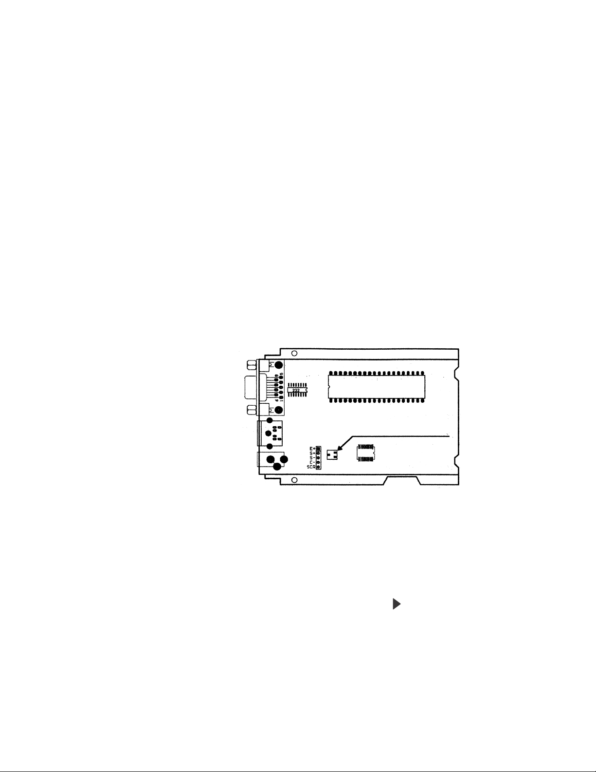
Dans ce mode, les données ADC adéquates au point zéro peuvent être consultées en
POTENTIOMÈTRE DU POINT ZÉRO
MCU
CELLULE DE PESÉE
ALIMENTATION
RS232
ADC
UR1
examinant les données A-D pour le poids chargé.
m Si l’augmentation ADC de la capacité totale est NFS, l’intervalle zéro au
démarrage est fixé à Zp % FS (réglage P12) et l’intervalle de la touche
zéro est fixé à Zk % FS (réglage P13). C’est que la valeur ADC
adéquate du point zéro est supérieure à (Zp %+ Zk %) x NFS.
1. Dans le mode de pesée, tenir enfoncées les touches [ON/OFF/ZERO] et
[HOLD/PRINT] (RETENIR/IMPRIMER) jusqu’à ce que Code s'affiche.
L’indicateur affichera la version du micrologiciel.
2. Une augmentation ADC à pleine capacité (NFS) peut être effectuée en
chargeant le poids (W) sur la plateforme et l’augmentation ADC de W est Nw.
L’augmentation ADC de la pleine capacité WFS est WFS is (NFS)=
(Nw)x (WFS)/W.
2a. Il est possible qu’une valeur négative soit affichée à cause d’une erreur de la
cellule de pesée ou à cause de la position du potentiomètre point zéro sur
PCB. Cependant, le logiciel ne traite que les valeurs positives. Dans ce cas,
la position du potentiomètre point zéro devra être ajusté pour que les données
ADC soient positives et supérieures à (Zp %+ Zk %) x NFS. Normalement,
l’indicateur est calibré en usine et ne requiert aucun ajustement. Pour savoir
où est situé le potentiomètre du point zéro, voir la Figure 5.1. Le chiffre ADC
diminue en faisant tourner le potentiomètre dans le sens horaire et aug men te
en faisant tourner le potentiomètre dans le sens antihoraire.
Figure 5.1 Emplacement du potentiomètre du point zéro
3. Appuye r sur la touc he [UNIT] (UNITÉ) pour cho isir le code in terne de po ids
ADC ou pour saisir la valeur de tension fonctionnelle interne. Les chiffres
affichés lorsque Ux.xx est affiché correspondent à la tension. La tension de
fonctionnement adéquate est située entre 5 et 8 V.
4. Pour afficher les données A-D de pesé e sans filtrage, appuyer sur la tou che
[TARE] (TARE). Les données sont filtrées si est allumé.
5. Pour quitter ce m ode et retou rner au mo de de pesé e normal, app uyer sur la
Mode d’emploi du MS140/300 27
touche [ON/OFF/ZERO].
Page 67
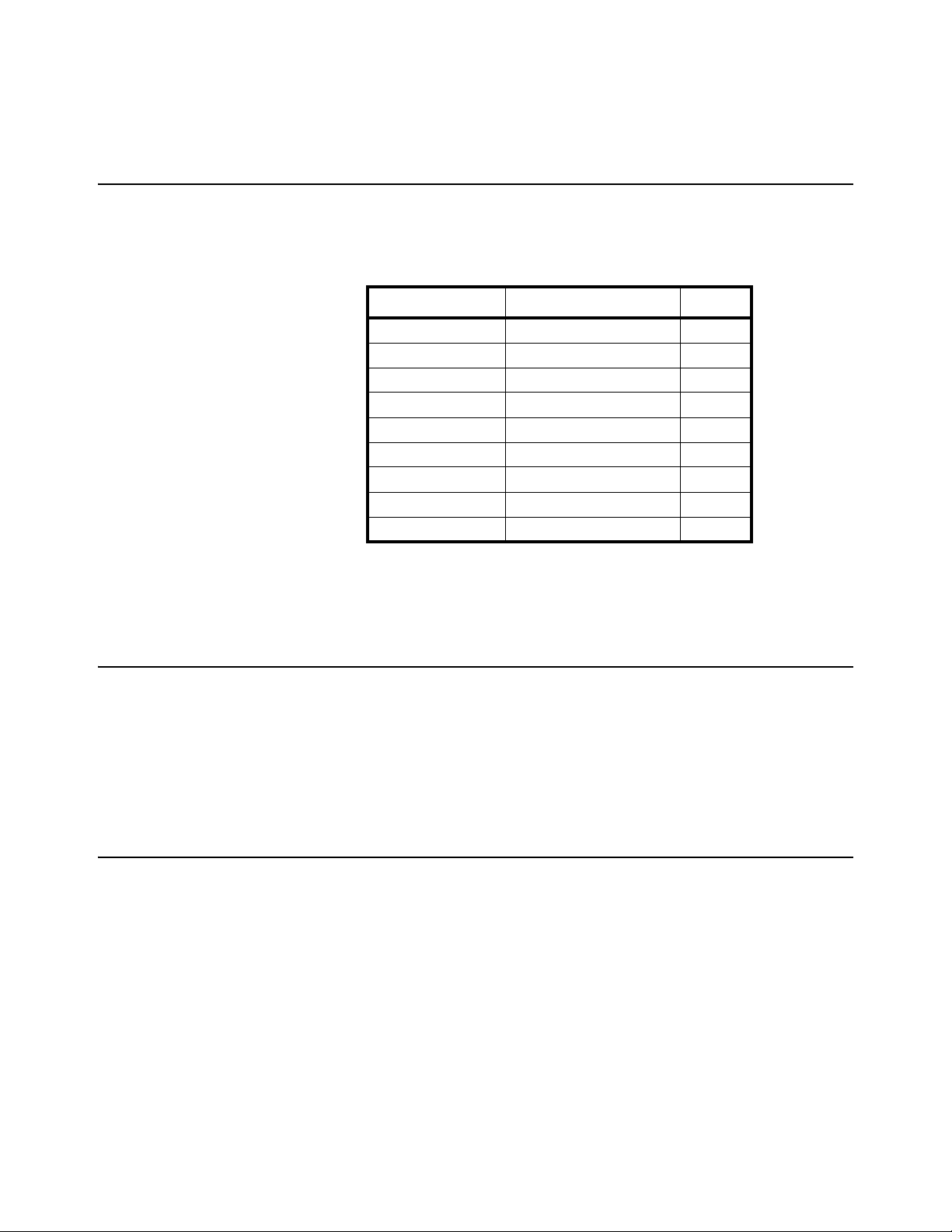
6 Communications de série
6.1 Port Com 1
COM1 est un port bidirectionnel RS-232. Les fils de communication sont bran chés au
connecteur RS-232 utilisant TXD1, RXD1 et GND
Table 6.1 Port PS-500 Com1
Désignation Description Broche
TXD Transmission 2
RXD Réception 3
GND Mise à la terre/commun 5
DSR Ensemble de données prêt 4
DTR Terminal de données prêt 6
CTS Prêt à transmettre 7
RTS Retour pour transmettre 8
Aucune connexion Aucune connexion 1
Aucune connexion Aucune connexion 9
NOT A : Les broches 4 et 6 du connecteur femelle de l’indicateur DB9 sont reliées.
Les broches 7 et 8 sont aussi reliées.
6.2 Protocole
La vitesse de transmission et le format d'octet sont déterminés p ar les p aramètr es P5
et P6.
Les réponses aux commandes série seront immédiates ou en moins d'un cycle de
pesée de la balance. Une valeur d’arrêt d’ une seconde devrait suffire pour l’appareil de
contrôle distant.
6.3 Séquence de transaction
La longueur du champ d'affiche de poids sera de 7 caractères. Un caractère pour le
signe moins, un pour le point décimal, 2 pour l'unité de mesure.
l Si l’unité est lb:oz, deux autres pour lb et un pour l’espace après lb. Les
abréviations des unités de mesure sont toujours en minuscules.
l Si le poids dépasse la capacité, la balance affichera 9 caractères « ^ »
(le champ du signe moins, le point décimal, et le champ de valeur de pesée
sont remplis de « ^ »).
l Si le poids est inférieur à la capacité, la balance affichera 9 caractères « _ »
(le champ du signe moins, le point décimal, et le champ de valeur de pesée
sont remplis de « _ »).
l Si le point zéro est erroné, neuf caractères « _ » seront affichés. Le
caractère sera un « - » si le poids est négatif ou une espace si le poids est
positif. Le signe de moins suit le premier caractère.
28 Mode d’emploi du MS140/300
Page 68
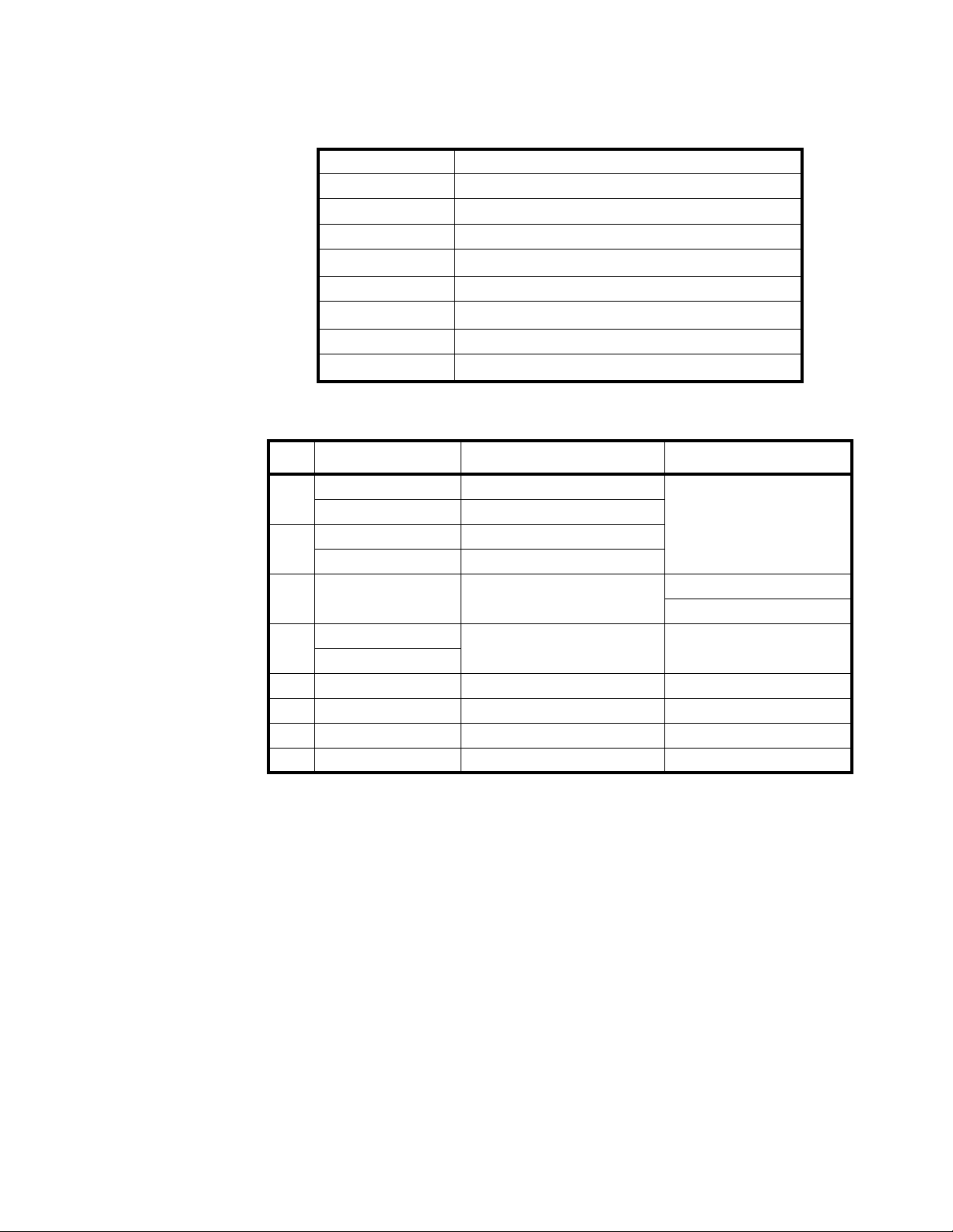
Le premier zéro avant les chiffres est supprimé.
Table 6.2 Symboles utilisés
<LF> Caractère d’alimentation (hex 0AH)
<CR> Caractère de retour de chariot (hex 0DH)
<ETX> Caractère de fin de texte (hex 03H)
<SP> Espace (hex 20H)
H
1H2H3
Quatre octets de l’état actuel
<P> Caractère de polarité : « ? » ou « »
---W
W
1
7
Données de lecture, 1-7 octets (sept caractères)
<DP> Point décimal
U
1U2
Unités de mesure units, kg, lb, lb:oz, % ou pcs; 2–5 octets
Bit
Octet 1 (H
Table 6.3 Définition d'un octet de H
) Octet 2 (H2) Octet 3 (H3)
1
1H2H3
0 0 = stable 0 = pas sous la capacité 00 = comparaison désactivée
1 = instable 1 = sous la capacité
1 0 = pas au point zéro 0 = pas au-dessus de la capacité
01 = limite inférieure
10 = ok
11= limite supérieure
1 = au point zéro 1 = au-dessus de la capacité
2 toujours 0 toujours 0 0 = poids brut
1 = poids net
3 0 = eeprom OK toujours 0 toujours 0
1 = erreur eeprom
4 toujours 1 toujours 1 toujours 1
5 toujours 1 toujours 1 toujours 1
6 toujours 0 toujours 1 toujours 0
7 parité parité parité
Mode d’emploi du MS140/300 29
Page 69
6.4 Commandes et réponses
Commande : W<CR> (57h 0dh), demander la lecture actuelle
Réponse
<LF>^^^^^^^^U
<LF>_ _ _ _ _ _ _ _ U
<LF> - - - - - - - - U
Nota : Si l’unité de pesée est lb:oz, U
<LF><P>W
<CR><LF> H1H2H3 <CR><ETX>---au-dessus de la capacité
1U2
<CR><LF> H1H2H3 <CR><ETX>---sous la capacité
1U2
<CR><LF> H1H2H3 <CR><ETX>---erreur de point zéro
1U2
oz dans les réponses ci-dessus
1U2
1W2W3W4W5W6
<DP>W7 U1U2<CR><LF> H1H2H3 <CR><ETX>---la balance est stable et l’unité
de pesée actuelle est kg ou lb. Avec ou sans point décimal et la position est conforme au réglage P9.
<LF><P>W
<LF><P>W
lb<SP>W4W5lb<SP>W6W7oz<CR> H1H2H3<CR><ETX>
1W2W3
lb<SP>W4lb<SP>W5W6<DP>W7oz<CR> H1H2H3<CR><ETX>
1W2W3
Commande : S<CR> (53h 0dh), demande l'état actuel
Réponse
<LF> H
1H2H3
<CR><ETX>
Commande : Z<CR> (5ah 0dh)
Réponse
La fonction Zéro est activée (simule la touche ZERO) et retour à l’état actuel de la balance.
<LF> H
1H2H3
<CR><ETX>
Si la fonction ZERO (ZERO) ne peut être activée, retour à l’état actuel de la balance.
Commande : T<CR> (54h 0dh)
Réponse
La fonction TARE (TARE) est activée (simule la touche TARE), et retour à l’état actuel de
la balance.
<LF> H
<CR><ETX>
1H2H3
Si la fonction TARE (TARE) ne p eut être activée, retour à l’état actuel de la balance.
30 Mode d’emploi du MS140/300
Page 70
Commande : U<CR> (55h 0dh)
Réponse
Change l’unité de mesure (simule la touche UNIT (UNITÉ)) et retour à l’état actuel de la balance, avec la nouvelle unité.
La nouvelle unité de mesure devrait être disponible
<LF> U
<CR><LF> H1H2H3<CR><ETX>
1U2
Commande : L<CR> (4ch 0dh)
Réponse
Si la fonction Hold (Retenir) peut être activée, elle activera ou désactivera la fonction Hold (simulation de la touche HOLD
(RETENIR)) et retour à l’état de la balance.
<LF> H
1H2H3
<CR><ETX>
Commande : X<CR> (58h 0dh)
Réponse
Éteint la balance, (simule l’action de la touche ON/OFF pour éteindre la balance).
Commande : Toutes les autres
Réponse
Commande inconnue
<LF>? <CR><ETX>
Table 6.4 Sommaire des commandes et des réponses :
Commande Réponse
ASCII HEX
W<CR> 57 0d Lecture du poids de la balance :
<LF>^^^^^^^^U1U2 U3U4U5<CR><LF> H1H2H3 H4<CR><ETX>--- hors
capacité
?<LF>________U1U2U3U4U5<CR><LF> H1H2H3 H4<CR><ETX>---sous
capacité
?<LF>-------- U1U2 U3 U4U5<CR><LF> H1H2H3 H4<CR><ETX>---erreur de
point zéro
?<LF><p>W1W2W3W4W5<dp>W6U1U2U3U4U5<CR><LF>H1H2H3H4<CR
><ETX>---données normales
S<CR> 53 0d <LF> H1H2H3H4<CR><ETX>; lecture de l’état de la balance
Z<CR> 5a 0d <LF> H1H2H3H4<CR><ETX>; simule la touche ZERO
T<CR> 54 0d <LF> H1H2H3H4<CR><ETX>; simule la touche TARE (TARE)
U<CR> 55 0d <LF> U1U2 U3 U4U5<CR><LF> H1H2H3H4<CR><ETX>; simule la touche
UNIT (UNITÉ)
L<CR> 4c 0d <LF> H1H2H3H4<CR><ETX>; simule la touche HOLD (RETENIR)
X<CR> 58 0d éteint la balance, simule la touche OFF
autres <LF>? <CR><ETX>
Mode d’emploi du MS140/300 31
Page 71
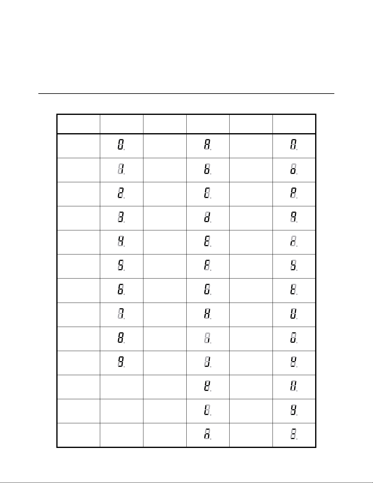
7 Dépannage
Ce chapitre fournit des explications sur les erreurs fréquentes, les caractères et les
symboles affichés.
7.1 Caractères d’affichage
ASCII
0AN
1BO
2CP
3DQ
4ER
5FS
6GT
Caractères
d’affichage
ASCII
Caractères
d’affichage
ASCII
Caractères
d’affichage
7HU
8IV
9JW
KX
LY
MZ
32 Mode d’emploi du MS140/300
Page 72
7.2 Symboles affichés
Symbole Description
0-----0_______
Ad-----Ad______
-------________
eep.e0
EEP.E1
EEP.E2
Lo.bAt
CAP.- CAL.Px
CAL.Er
d.-px.y
Le zéro est au-dessus de l’intervalle du paramètre
Le point zéro est sous l’intervalle du paramètre
Le signal à ADC est au-delà de l’intervalle
Le signal à ADC est en-deçà de l'intervalle
Le poids dépasse la limite maximale ou les données d’affichage dépassent les limites
Le poids est inférieur à la limite minimale
EEPROM est inaccessible
Les paramètres ne sont pas les mêmes que les données de sauvegarde
Le(s) paramètre(s) du réglage n'est (ne sont) pas à l'intérieur de l'intervalle normal
La tension de la batterie est inférieure à 4,7 V
La capacité du réglage sera affichée
Calibrage au point (x)
Erreur de calibrage, peut-être que les données saisies ou le poids chargé sont inexacts,
instables ou non linéaires
La division sera affichée
Le choix entre x=paramètre et y=paramètre
7.3 Messages d’erreur et dépannage
Symptôme Cause probable Solution
Ad-----Ad______
0------
0______
--------
________
EEP.E2
CAL.Er
Impossible d’allumer la
balance.
Impossible de remettre
à zéro l’affichage ou
ne se remet pas à zéro
à l’allumage.
Les fils de la cellule de charge à l'indicateur ne sont pas
correctement branchés, sont court-circuités, ouverts,
l'ADC ou la cellule de charge sont endommagés.
La lecture de poids dépasse la limite de démarrage à
zéro.
La lecture de poids est inférieure à la limite de démarrage
à zéro.
La lecture du poids dépasse la limite de surcharge ou la
valeur de poids ne peut être affichée dans l’unité de
mesure actuelle car elle dépasse les 6 chiffres.
Lecture de poids sous la limite de charge. Poser la plateforme sur la balance. Effectuer le
Le paramètre n’est pas correctement réglé. Régler le paramètre.
Erreur de calibrage. Les données saisies ou la charge
sont trop petites, trop importantes, instables ou non
linéaires.
Le cordon d’alimentation n’est pas branché ou
incorrectement branché. La prise électrique n’est pas
alimentée. La batterie est à plat. Autre défaut.
La charge sur la balance dépasse la limite. La charge sur
la balance n’est pas stable. La cellule de charge est
endommagée.
S’assurer que les fils sont en bon état et bien
branchés. Remplacer la cellule de charge ou la
puce ADC; entretien nécessaire.
S’assurer que la plateforme de la balance est
vide. Effectuer le calibrage à zéro.
Poser la plateforme sur la balance. Effectuer le
calibrage à zéro.
Réduire la charge sur la balance jusqu’à ce que
la valeur puisse être affichée. Utiliser une unité
de mesure plus appropriée.
calibrage à zéro.
Saisir les données correctement, charger le
poids correctement sur la plateforme, entretien
requis.
Vérifier les raccords du cordon d'alimentation.
Vérifier que le cordon d’alimentation est branché
à la prise électrique. Vérifier la source
d’alimentation. Remplacer les batteries.
Entretien requis.
Retirer la charge de la balance. Attendre que la
charge se stabilise. Entretien requis.
Mode d’emploi du MS140/300 33
Page 73

34 Mode d’emploi du MS140/300
Page 74

Page 75

Page 76

Brecknell USA
1000 Armstrong Dr.
Fairmont MN 56031
Tél. : 507-238-8702
Téléc. : 507-238-8271
Courriel : [email protected]
http://www.brecknellscales.com
Brecknell UK
Foundry Lane
Smethwick, West Midlands,
England B66 2LP
Tél. : +44 (0) 8452 46 6717
Téléc. : +44 (0) 8452 46 6718
Courriel : [email protected]
http://www.brecknellscales.com
 Loading...