

Page 1

Service Manual PV 501/501-2
Table of contents
1 INTRODUCTION ....................................................................................................... 1
1.1 The scope of this manual ............................................................................ 1
1.2 Intended use of the ventilator ...................................................................... 1
1.3 Design and function of the ventilator ........................................................... 1
1.4 Intended audience ....................................................................................... 1
1.5 Service personnel's training requirements .................................................. 2
2 OPERATING MANUAL
3 MAINTENANCE SERVICE INSTRUCTIONS ........................................................... 1
3.1 Verifying the components and software installed ........................................ 1
3.2 Maintenance Service Schedule................................................................... 1
3.3 Special safety precautions .......................................................................... 2
3.4 Equipment required ..................................................................................... 3
3.5 Replacement parts required ........................................................................ 3
3.6 Maintenance instructions ............................................................................. 3
3.6.1 Registration ................................................................................. 3
3.6.2 Information from the user ............................................................ 3
3.6.3 Validity of documentation ............................................................ 3
3.7 External checks ........................................................................................... 4
3.7.1 External damage and wear ......................................................... 4
3.7.2 Power cables and plugs.............................................................. 4
3.7.3 Minimum function check ............................................................. 4
3.8 Internal Checks ........................................................................................... 4
3.8.1 Open hood and rear panel .......................................................... 4
3.8.2 Cleaning...................................................................................... 4
3.8.3 Cables and connectors ............................................................... 4
3.8.4 Component fastening.................................................................. 4
3.8.5 Mains supply ............................................................................... 5
3.8.6 Remove and check / replace the motor unit. .............................. 5
3.8.7 Grease the ball screw ................................................................. 5
3.8.8 Replace the membranes in the check valves ............................. 5
3.8.9 Leakage check of hoses and bellows ......................................... 5
3.8.10 Reassemble the motor unit ......................................................... 5
3.8.11 Checking the offset and gain of the pressure transducer ........... 5
3.8.12 Checking the instrument accuracy.............................................. 5
3.8.13 Internal battery test ..................................................................... 5
3.8.14 Reassemble the casing .............................................................. 6
3.9 Electrical safety ........................................................................................... 6
3.10 Final checks before delivery........................................................................ 6
3.10.1 Function check/leakage .............................................................. 6
3.10.2 Check the tidal volume/frequency ............................................... 6
3.10.3 Calculating the tidal volume/patient pressure ............................. 7
3.10.4 Checking the pressure limit ........................................................ 7
3.10.5 Checking low pressure alarm/alarm mute .................................. 8
3.10.6 Trigger ........................................................................................ 8
Doc. No.: 1523EN Issue: N-1 BREAS MEDICAL 1 – 0
Page 2

Service Manual PV 501/501-2
3.10.7 Battery operation ........................................................................ 8
3.10.8 Checking accessories ................................................................. 8
3.10.9 Cleaning the PEEP adapter ........................................................ 9
3.10.10 Set the correct values for the patient ........................................ 10
4 REPLACEMENT PARTS .......................................................................................... 1
4.1 OVERVIEW DIAGRAM ............................................................................... 1
4.2 Exploded drawing, Base Plate Assembly PV 501 ....................................... 2
4.3 Exploded drawing, Base Plate Assembly PV 501-2 .................................... 3
4.4 Exploded drawing, Motor Unit Assembly PV 501........................................ 4
4.5 Exploded drawing, Motor Unit Assembly PV 501-2 ..................................... 5
4.6 Exploded drawing, Rear Panel Assembly PV 501 ...................................... 6
4.7 Exploded drawing, Rear Panel Assembly PV 501-2 ................................... 7
4.8 Exploded drawing, Hood Assembly 501 ...................................................... 8
4.9 Exploded drawing, Hood Assembly 501-2 .................................................. 9
4.10 Part Number List ....................................................................................... 10
5 FUNCTIONAL DIAGRAMS ....................................................................................... 1
5.1 Pneumatic diagram ..................................................................................... 1
5.2 Functional block diagram ............................................................................ 2
6 DISMANTLING AND ASSEMBLING THE PV 501/PV501-2 ..................................... 1
6.1 Opening the hood ........................................................................................ 1
6.2 Replacing pushbutton boards ...................................................................... 2
6.3 Replacing the CPU board ............................................................................ 3
6.4 Replacing the potentiometer board ............................................................. 4
6.5 Opening the rear panel................................................................................ 5
6.6 Replacing the MDA board ........................................................................... 5
6.7 Removing the motor unit ............................................................................. 6
6.8 Reassembling the motor unit ....................................................................... 7
6.9 Assembling the hood and rear panel ........................................................... 7
7 MOTOR UNIT ............................................................................................................ 1
7.1 Construction ................................................................................................ 1
7.2 Lubricating the ball screw ............................................................................ 2
7.3 Replacing the membranes in the check valves ........................................... 3
7.4 Hoses and bellows, leakage check ............................................................. 3
7.5 Wiring diagram, Motor unit .......................................................................... 4
8 ELECTRONICS ......................................................................................................... 1
8.1 Function, Construction ................................................................................ 1
8.2 PV 501/PV 501-2's circuit boards ................................................................ 2
8.3 Pushbutton board ........................................................................................ 3
8.4 Potentiometer board .................................................................................... 3
8.5 MDA board .................................................................................................. 4
8.5.1 Checking the pressure transducer offset and gain ..................... 5
8.5.2 Checking the instrument accuracy .............................................. 5
8.6 CPU board ................................................................................................... 6
8.7 Terminal diagram, test points ....................................................................... 7
8.8 Measuring points on the motor unit ........................................................... 10
1 – 1 BREAS MEDICAL Doc. No.: 1523EN Issue:N-1
Page 3

Service Manual PV 501/501-2
8.9 Internal Battery test ................................................................................... 11
8.10 Replacing the internal power batteries (lead acid cells) ............................ 11
8.11 Replacing the alarm batteries (Ni-Cd) ....................................................... 12
8.12 Electrical safety ......................................................................................... 13
8.12.1 Mains ........................................................................................ 13
8.12.2 Isolation .................................................................................... 13
8.12.3 Leakage current ........................................................................ 13
8.12.4 Leakage current from the cabinet ............................................. 13
8.12.5 Patient leakage ......................................................................... 13
8.12.6 Leakage current at mains voltage at patient connected part .... 13
8.13 Wiring Diagrams PV 501/501-2 ................................................................. 14
8.14 Functional block diagram PV6 T1 ............................................................. 30
8.15 COMPONENT LOCATION DRAWINGS PV 501 ...................................... 31
8.15.1 Pushbutton Boards PV 501, Versions B & E ............................ 31
8.15.2 Potentiometer Board PV 501 ................................................... 31
8.15.3 CPU Boards PV 501, Version B & E ......................................... 32
8.15.4 MDA Boards PV 501 ................................................................. 33
8.16 COMPONENT LOCATION DRAWINGS PV 501-2 ................................... 35
8.16.1 Pushbutton Boards PV 501-2 ................................................... 35
8.16.2 Potentiometer Board PV 501-2 ................................................. 36
8.16.3 CPU Boards PV 501-2 .............................................................. 37
8.16.4 MDA Boards PV 501-2 XA ........................................................ 38
8.17 List of components PV 501 ....................................................................... 39
8.18 List of components PV 501-2, Rev. XD ..................................................... 44
9 FAULT TRACING...................................................................................................... 1
9.1 Fault tracing guide ....................................................................................... 1
9.2 Error codes .................................................................................................. 3
9.3 Recalling error codes .................................................................................. 3
9.4 Erasing the error code memory ................................................................... 3
9.5 ERROR CODE TABLE................................................................................ 4
9.6 Fault tracing using the error codes .............................................................. 5
10 ENGINEERING CHANGE HISTORY PV501 AND PV501-2 .................................... 1
10.1 Service record for BREAS PV501/PV501-2
Doc. No.: 1523EN Issue: N-1 BREAS MEDICAL 1 – 2
Page 4

Service Manual PV 501/501-2 INTRODUCTION
1 INTRODUCTION
1.1 The scope of this manual
This manual provides information for the maintenance and service of both the PV 501
and PV 501-2 ventilators. The PV 501-2 is a further development of the PV 501. The
main differences are that the PV 501-2 delivers a maximum patient pressure of 60 mbar
(compared to the PV 501’s 50 mbar) and that theTrigger setting is adjustable between -
-2 to 6 mbar (compared to the PV 501’s -4 to 6 mbar).
The PV 501and PV 501-2 are designed to give many years of trouble-free breathing
assistance to the user provided that preventative maintenance is done at the specified
intervals described in this manual. Correctly performed maintenance will increase the
ventilator's service life considerably.
All points to be checked and service instructions for the PV 501 and the PV 501-2 are
described in this manual. Where information is only relevant to one of the models it is
clearly marked which model the text/figure refers to, otherwise all information is valid for
both models.
It is also important that any peripheral equipment is checked at the same time as the
maintenance service is done.
Also included is a reference copy of the Operation Manual.
1.2 Intended use of the ventilator
PV 501 and the PV 501-2 are volume-controlled, pressure-limited ventilators, specially
designed for long term ventilator assistance at home.
The internal batteries are connected automatically should the mains supply fail or is disconnected. Fully-charged batteries will give a running time of 4 hours.
Thanks to its design, the PV 501 and the PV 501-2 are easy to operate. It does not
require any gas, and together with its low weight, it is ideal for breathing therapy both in
hospital and while travelling.
The PV 501and the PV 501-2 are not intended for intensive care and are aimed for
adults and children weighing about 30 kg or more.
1.3 Design and function of the ventilator
The PV 501and the PV 501-2 are built around a bellows that is compressed and drawn
out by a ball screw driven by an electronically controlled servo motor. The micro-processor controlled electronics calculate the correct speed and running time for the motor by
reading the settings for tidal volume, frequency and the I/E-relationship. The setting limits for pressures and the trigger level are monitored. If the mains supply or the external
battery supply should fail during operation, the internal batteries are automatically connected and an indication of this is given on the front panel. If the battery supply voltage
drops too low, both audible and visual alarms are given. The ventilator's modular design
makes maintenance easy.
1.4 Intended audience
This Service Manual is intended for technicians who have medical/technical training and
knowledge about the construction and function of the ventilator.
It is not intended for clinic personnel or patients.
Doc. No.: 1523EN Issue: N-1 BREAS MEDICAL 1 – 1
Page 5

INTRODUCTION Service Manual PV 501/501-2
Breas Medical reserves the right to make changes to the product and the contents of
this manual without prior notice.
1.5 Service personnel's training requirements
Thanks to their simple construction using a modular system, no special competence is
required other than general medical technical training on ventilators.
Always contact BREAS MEDICAL if there are any questions or if training is required.
All service must, however, be performed according to the instructions in this manual.
1 – 2 BREAS MEDICAL Doc. No.: 1523EN Issue:N-1
Page 6

Service Manual PV 501/501-2 MAINTENANCE SERVICE INSTRUCTIONS
3 MAINTENANCE SERVICE INSTRUCTIONS
All routine maintenance checks and additional se rvice instructions for the PV
501and PV 501-2 are described in this chapter. For information about fault-tracing, detailed drawings, board schematics, spare parts etc, please refer to the
respective chapters in this Service Manual.
The checks described in the Patient Instruction delivered with the ventilator
should be followed by the patient and/or care provi ders.
3.1 Verifying the components and software installed
Check the Engineering Change History document in the Appendices section
(Chapter 10) for a history of all the changes made and at which serial No they
were introduced.
If in any doubt, read the component designation on the motor unit, circuit boards
and PROMs as upgrades can have been made but not recorded.
3.2 Maintenance Service Schedule
IMPORTANT!
A complete maintenance service (as described in this chapter) must be done
every 12th month. If the ventilator is used for continuous operation (24 hours
per day) a complete maintenance service must be done every 6th month.
Interval Action
At every 500th operation hour or more frequent if
necessary (especially in town environments).
Every 6 months if the ventilator is used for continuous operation i.e. 24 hours per day, otherwise
every 12th month.
Additional service action (when required)
At 20.000 running hours Replace motor unit and hoses.
The internal batteries should be replaced every 24
months.
• Replace the alarm batteries every 5th year
counted from date of delivery or when
required.
Replace the patient air inlet filter.
Done by the patient/care provider.
Replace during maintenance service.
Complete maintenance service according to this instruction.
Replace the internal batteries
Replace the alarm batteries.
Doc. No.: 1523EN Issue: N-1 BREAS MEDICAL 3 – 1
Page 7

MAINTENANCE SERVICE INSTRUCTIONS Service Manual PV 501/501-2
Every 12th month or every 6th month if the ventilator is used
for continuous operation (24 hours per day)
Replace the patient air inlet filter. 2
Clean the ventilator air intake filter 2
Motor Unit
Lubricate the ball screw 7.2
Replace the check valve membranes in bellows end cover 7.3
Leakage test of motor unit and tubes 7.4
Electronics
Checking the pressure sensor offset and gain. 8.5.1
Check operation using internal battery 8.9
Check operation using external battery 2
Check electrical safety levels 8.13
Internal Batteries (lead-ac id)
The internal batteries should be replaced every 24 months or when necessary.
Section No.
8.10
See Ch./
Alarm Batteries
Replace every 5th year counted from date of delivery or when last
replaced.
Accessories (where applicable)
Inspect patient circuit 2
Replace membrane in exhalation valve 2
Clean PEEP adapter, replace O-ring 2
Every 20000 operation hours
Replace the complete Motor unit 6.6
3.3 Special safety precautions
• Avoid working with the mains c onnect ed when the casi ng is r emoved. Always tes t
run using internal battery power.
• Insulate the wires for the inter nal batte ri es when they are di sconne cted to prev ent
short circuits.
• Explosive gases or liquids must not be kept or used close to the ventilator.
8.11
• Always follow good ESD practices when working with the ventilator.
3 – 2 BREAS MEDICAL Doc. No.: 1523EN Issue: N-1
Page 8

Service Manual PV 501/501-2 MAINTENANCE SERVICE INSTRUCTIONS
3.4 Equipment required
• Test lung (1L) with exhalation valve.
• Measuring equipment for tidal vol ume and minut e volume/frequency. (Timeter,
Spirometeor or equivalent).
• Voltmeter.
3.5 Replacement parts required
Have the following spare parts at hand:
Part No.
000 139 Internal battery (lead)
000 036 Alarm battery (Ni-Cd)
001 141 Motor unit, BEI
000 557 Grease (BREAS 283 AZ)
000 004 Motor unit, Maxon
000 248 Filter, patient air
002 123 Service kit, check valves
002 178 Membrane kit, exhalation valve
Description
3.6 Maintenance instructions
3.6.1 Registration
• Fill out the registration part of the Service Record. Check that the following markings can be read:
• Make, model designation and serial number.
• All warning texts on labels.
• Any inventory control markings.
• Document the current patient settings.
• Note the number of running hours. Does the motor unit need to be replaced?
• Check any comments or events made on the previous service record.
3.6.2 Information from the user
• Before starting the service request the following information from the patient:
• Has the ventilator functioned problem-free, such as running failure?
• How does the patient check the function of the ventilator? How often?
• How often is the filter changed?
• What is the patient's need of filters unt il the next service point?
3.6.3 Validity of documentation
• Check that the patient instructions are up-to-date.
• Check if any modification or update of the ventilator is to be performed during the
service.
Doc. No.: 1523EN Issue: N-1 BREAS MEDICAL 3 – 3
Page 9

MAINTENANCE SERVICE INSTRUCTIONS Service Manual PV 501/501-2
3.7 External checks
3.7.1 External damage and wear
• Clean the surface with a mild detergent.
• Clean the filter for the machine ventila tor air inlet. Use a vacuum cleaner or wash
and dry the filter before fitting.
• Check that there is no visible damage on the surfaces and other components.
• Check that all texts for controls etc. are readable.
• Turn all knobs and check that their operation feels OK.
• Check that nothing is loose, (including the handles).
• Check that the cover for the adjustment panel is secu red properly.
3.7.2 Power cables and plugs
• Check the power cable and its plugs, and the power socket in the rear panel.
• Check that the cable securing clamp is undamaged.
• Check other external battery cables, where applicable.
3.7.3 Minimum function check
• Connect the ventilator to the mains and check that the LED for Mains/Charging is
lit.
• Start the ventilator and check that it oper ates normally and no abnormal noise is
heard. Check that the lighting for the press u re gauge is on.
• Check the condition of the internal batteries. They should, when fully charged, be
able to run the PV 501 for at least 2 hours. If not they must be replaced.
3.8 Internal Checks
3.8.1 Open hood and rear panel
• Remove the mains power cable.
• Open the hood and rear panel. Remove stabiliser bar, see chapter 6.
3.8.2 Cleaning
• Remove any dirt or dust that has collected in the ventil ator, also from the folds in
the bellows.
3.8.3 Cables and connectors
• Check all cables and thei r connectors for an y damage. Check at the fr ont and rear
panels where cables can be pinched.
3.8.4 Component fastening
• Check that the batteries are properly fastened.
• Check that the motor unit is properly fastened.
• Check that all parts on the front and rear panels are properly fastened.
3 – 4 BREAS MEDICAL Doc. No.: 1523EN Issue: N-1
Page 10

Service Manual PV 501/501-2 MAINTENANCE SERVICE INSTRUCTIONS
3.8.5 Mains supply
• Check that the power inlet socket is undamaged and that it is properly fastened.
• Check that the touch protection cover is undamaged and that it is properly fastened over the power inlet socket.
• Check that the transformer is properly fastened.
• Check the wiring to the transformer.
3.8.6 Remove and check / replace the motor unit.
The motor unit must be checked at each service. At 20.000 running hours the
entire motor unit assembly must be replaced. See Chapter 6 for removing the
motor unit.
Checking the motor unit
• Check that the motor is properly fastened.
• Check that the shaft coupling screws are properly tightened.
• Check that the encoders are undamaged and properly fastened.
3.8.7 Grease the ball screw
Use only BREAS grease type 283 AZ. See chapter 7.
3.8.8 Replace the membranes in the check valves
• The membranes must be changed at each maintenance service. See chapter 7.
3.8.9 Leakage check of hoses and bellows
• Check the function of the outlet check valves. See chapter 7.
3.8.10 Reassemble the motor unit
Before reassembling the motor unit, check if the internal batteries need to be
replaced as this is best done with the motor unit removed, see 3.8.6.
• Reassemble the motor unit. See Chapter 6.
3.8.11 Checking the offset and gain of the pressure transducer
• See Chapter 8, Section 8.5.1 for detail ed inf o rmation.
3.8.12 Checking the instrument accuracy
• Check using a manometer conne cted to the exh. valve connec tion t hat the i ndic ating instrument gives the correct indicati on and that the needle moves "softly".
See Chapter 8, Section 8.5.1.1.
NOTE! Make small pressure changes, the indicating instrument should be
"slower" compared with the manometer.
3.8.13 Internal battery test
The internal batteries should be fully charged or charged for at l east 12 hours with
the ventilator turned off before this test is carried out. The batteries, when fully
charged, should operate the PV 501 for at least 2 hours, if not t he batteries must
be replaced. See Chapter 8, Section 10.
Doc. No.: 1523EN Issue: N-1 BREAS MEDICAL 3 – 5
Page 11
MAINTENANCE SERVICE INSTRUCTIONS Service Manual PV 501/501-2
3.8.14 Reassemble the casing
See Chapter 6 for information.
3.9 Electrical safety
Follow the instructions for the following checks in Chapter 8.
• Check mains supply value
• Check isolation against the value obtained at the delivery inspection
• Check leakage current. Do not forget to reverse the polarity.
• Check patient leakage current.
• Leakage current at mains voltage at patient connected part
3.10 Final checks before delivery
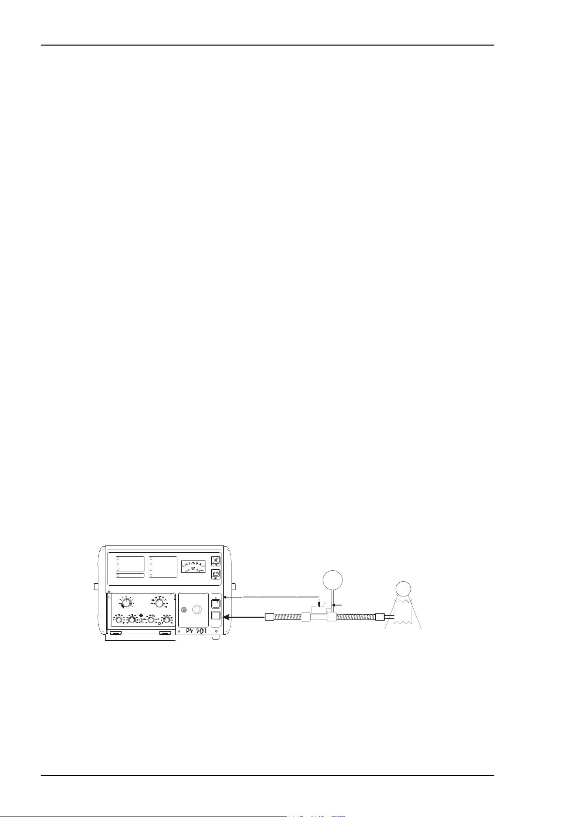
3.10.1 Function check/leakage
• Start the ventilator with the pat ient circuit and reservoir bag connected as shown
in the figure below. Check that everything seems normal. Create a pressure of
approximately 30 cm H
0 and listen for any leakage.
2
3.10.2 Check the tidal volume/frequency
Set: Tidal vol ume: 1L
Frequency: 12
I/E: 1:2
• Measure the tidal volume and that the volume per minute is cor rect.
(Accuracy ± 10%).
When checking using a volume monitor, an exhalation valve with a peep valve
connector can be required. The volume monitor is then connected to the peep
valve outlet on the exhalation valve.
LOW PRESSURE
HIGH PRESSURE
LOW BATTERY
FUNCTION FAIL URE
TIDAL VOLUME
Litre
Setting error
Setting error
Setting errorSetting error
PATIENT PRESSUREALARMS
Peep valve connector
EXHALATION
VALVE
BPM
BPMcm HO
BPMBPM
POWER
PATIEN T
AIR
ON
OFF
LOW PRESSURE
cm HO
cm HOcm HO
POWER
AC/CHARGING
EXTERNAL BATTERY
INTERNAL BATTERY
TRIGGER
Off
Off
OffOff
TRIGGER
cm HO
2
HIGH PRESSURE
2222
Signal
Signal
SignalSignal
I/E BREATH RATE
cm HO
cm HO
Ratio
Ratio
cm HOcm HO
RatioRatio
2222
mbar
Volume monitor
Test lung / Reservoir bag
Fig. 3-1 Tidal volume check
3 – 6 BREAS MEDICAL Doc. No.: 1523EN Issue: N-1
Page 12
Service Manual PV 501/501-2 MAINTENANCE SERVICE INSTRUCTIONS
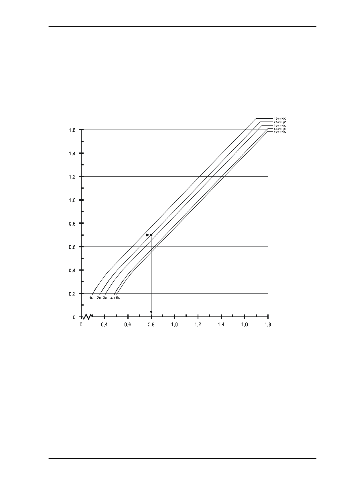
3.10.3 Calculating the tidal volume/patient pressure
The tidal volume delivered is always slightly less than the tidal volume setting.
This difference is due to the effect of the patient pressure on the compliance of
the bellows.
The diagram below shows these differences at different patient pressures.
Settings: I/E = 1:2, Breath rate = 15 breaths/min. with the patient circuit con-
nected.
Set volume/l itr e s
Fig. 3-2 Volume/Patient pressure diagramme
Example:
A patient needs a tidal volume of 0,7 litres and has an airway pressure of 20 cm
O. Start from 0.7 on the axis for “ Delivered volume”. Draw a horizont al line unti l
H
2
it crosses the line for 20 cm H
O patient pressure. From this point, go straight
2
down and read off the value the tidal vol ume setti ng should be. In this case the
ventilator setting is 0.8 litres.
Doc. No.: 1523EN Issue: N-1 BREAS MEDICAL 3 – 7
Page 13
MAINTENANCE SERVICE INSTRUCTIONS Service Manual PV 501/501-2
1
3.10.4 Checking the pressure limit
Set: Low pressure 10 cmH2O
High pressure 40 cmH
• Check the accuracy (±10%). Check that LED indicati on is given as well as an
audible alarm.
• Also check that the solenoid valve for high pressure "clicks". You can clearly hear
the solenoid valve activate at the following inhalation.
O
2
3.10.5 Checking low pressure alarm/alarm mute
• Turn the vent ilator on without anything connected to the patient air outlet. Wait 15
sec until the alarm for "Low pressure" is activated. Press the alarm mute button
and check that the alarm is heard again after approx. 2 min.
3.10.6 Trigger
• Set the trigger knob to -1 c m H20. Create a negative pressure an d check that ther e
is a triggered inhalation. The green LED should light.
3.10.7 Battery operation
• Disconnect the mains cable while the ventilat or is running. Check that the ventilator automatically changes over to internal battery and an alarm is given.
• Reconnect the mains power and check that indication "MAINS" comes on.
3.10.8 Checking accessories Patient circuit
• Inspect the patient circuit and replace it if necessary.
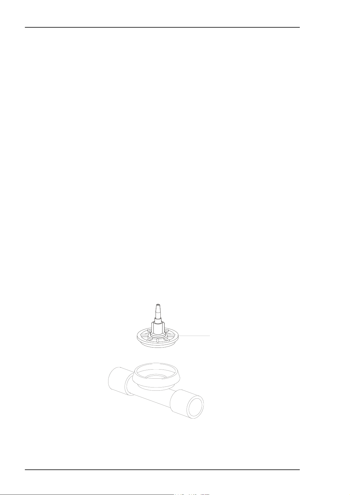
Replacing the membrane assembly in the exhalation valve
This instruction applies to BREAS exhalation valves, see figure below.
Fig. 3-3 Mounting the exhalation valve
• Remove the PEEP adapter , if installed. See "Cleaning the PEEP adapter".
3 – 8 BREAS MEDICAL Doc. No.: 1523EN Issue: N-1
Page 14
Service Manual PV 501/501-2 MAINTENANCE SERVICE INSTRUCTIONS
• Unscrew and remove the complete membrane assembly (1).
• Clean the inside of the exhalation valve using a moist rag or wash in hot water
using a washing-up liquid. Let it air dry.
• Screw on the new membrane assembly
• If a PEEP valve is to be used, fit the O-ring seal for the PEEP valve as shown in
fig. 3-5.
• Connect the exhalation valve to a test lung. Check that no leakage occurs during
the exhalation phase.
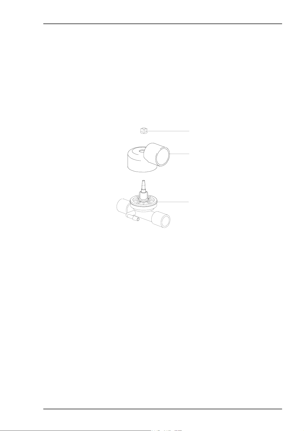
3.10.9 Cleaning the PEEP adapter
1
2
3
Fig. 3-4 Mounting the exhalation valve with PEEP adapter
• Remove the plastic nut (1) holding the PEEP adapter.
• Pull the adapter (2) up from the exhalation valve.
• Clean using a moist rag or wash in hot water using a washing-up l iqui d. Let the
adapter air dry.
• Check that the O-ring seal (3) is properly in place on the exhalation valve (under
the edge of the membrane assembly cover as shown in the figure below).
Note! Do not fit the O-r ing to the membrane assembly before screwing it on.
Doc. No.: 1523EN Issue: N-1 BREAS MEDICAL 3 – 9
Page 15
MAINTENANCE SERVICE INSTRUCTIONS Service Manual PV 501/501-2
Fig. 3-5 Mounting the O-ring for the PEEP adapter
• Fit the PEEP adapter to the exhalation valve and screw on the plastic nut
• Check any other accessories.
3.10.10Set the correct values for the patient
• Adjust the settings to the prescribed values for the patient.
• Change the air filter. Check that the patient has enough filters to last until the next
service.
The patient settings should be checked by a physician at least once a year.
3 – 10 BREAS MEDICAL Doc. No.: 1523EN Issue: N-1
Page 16
Service Manual PV 501/501-2 REPLACEMENT PARTS
4 REPLACEMENT PARTS
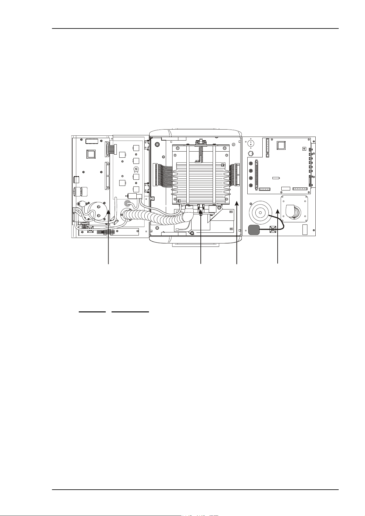
4.1 OV ERVIEW DIAGRAM
The illustration belo w shows the PV501/PV501-2, seen f rom above, with the ho od
and rear panel unscrewed and laid flat against the work surface.
The figure below shows the main units making up the PV501/PV501-2. The following pages contain detailed exploded drawings for each of the main units and
model. Last in this chapter is a complete list of part numbers.
1
Pos. No.
1 Hood assembly
2 Motor unit
3 Base plate assembly
4 Rear panel assembly
Component
2
3
4
Doc. No.: 1523EN Issue: N-1 BREAS MEDICAL 4 – 1
Page 17
REPLACEMENT PARTS Service Manual PV 501/501-2
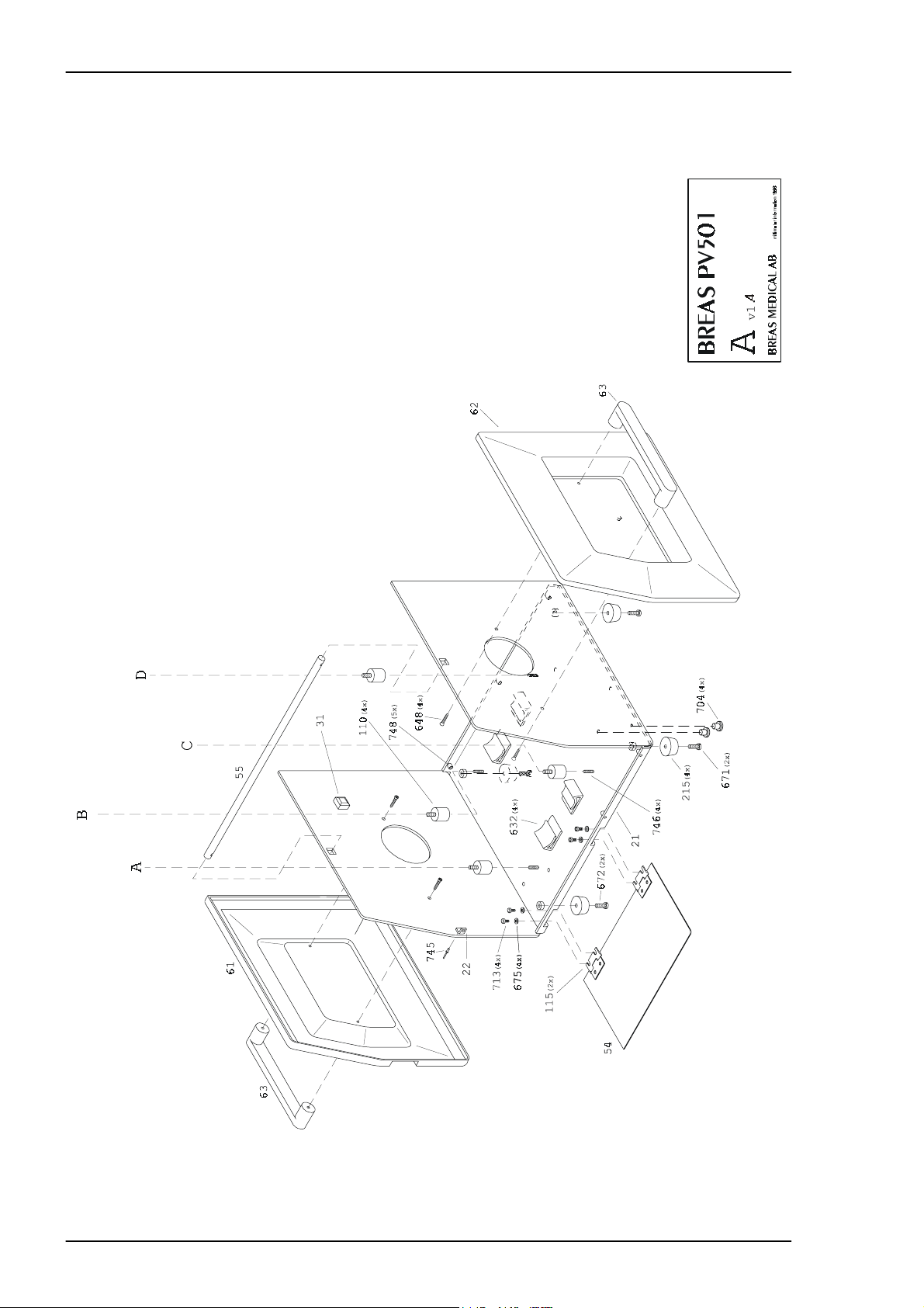
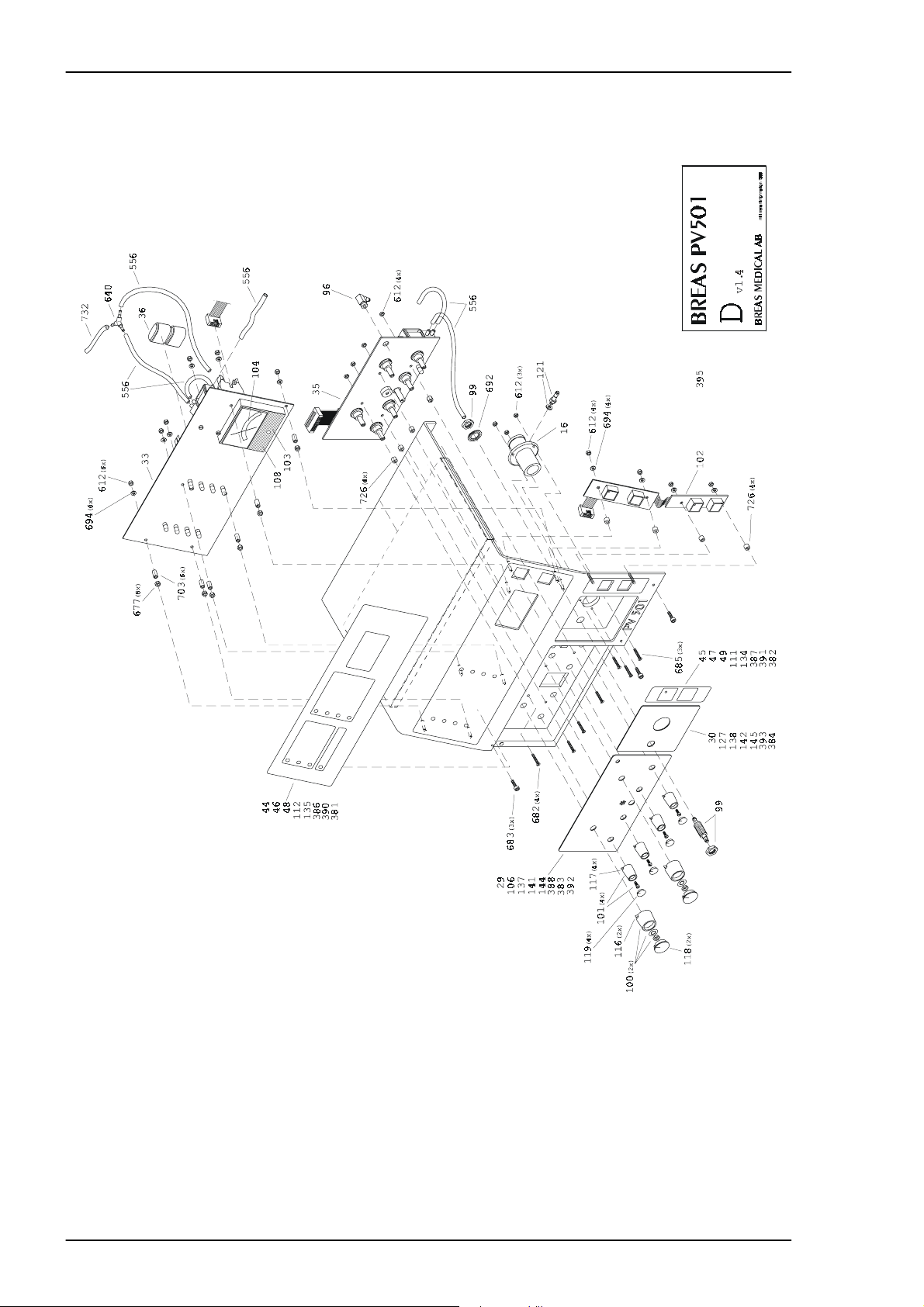
4.2 Exploded drawing, Base Plate Assembly PV 501
4 – 2 BREAS MEDICAL Doc. No.: 1523EN Issue: N-1
Page 18
Service Manual PV 501/501-2 REPLACEMENT PARTS
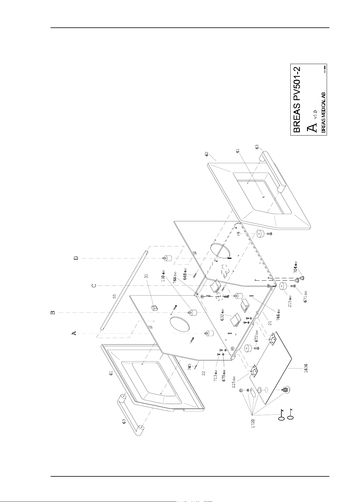
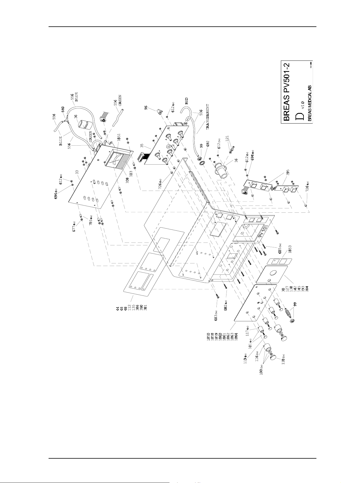
4.3 Exploded drawing, Base Plate Assembly PV 501-2
Doc. No.: 1523EN Issue: N-1 BREAS MEDICAL 4 – 3
Page 19
REPLACEMENT PARTS Service Manual PV 501/501-2
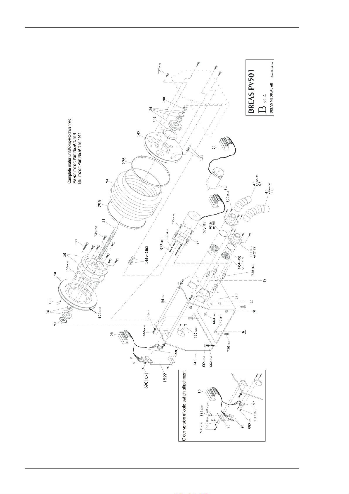
4.4 Exploded drawing, Motor Unit Assembly PV 501
4 – 4 BREAS MEDICAL Doc. No.: 1523EN Issue: N-1
Page 20
Service Manual PV 501/501-2 REPLACEMENT PARTS
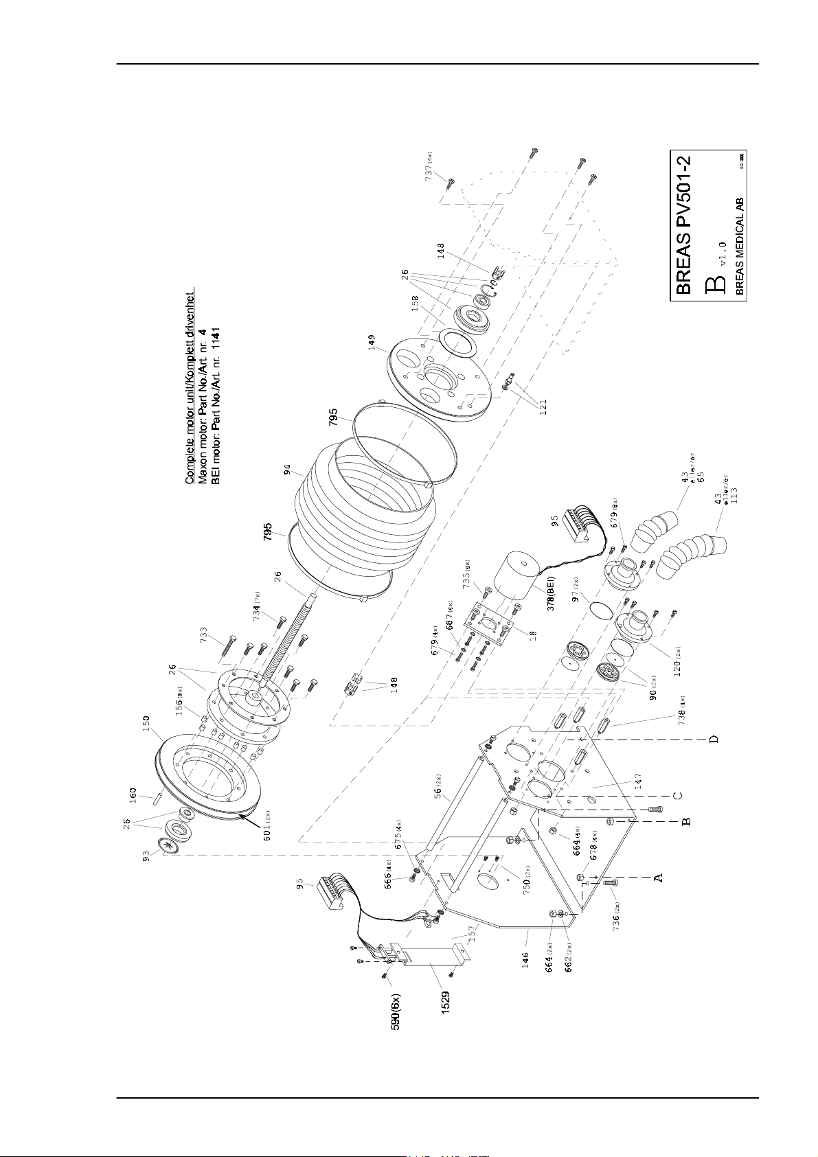
4.5 Exploded drawing, Motor Unit Assembly PV 501-2
Doc. No.: 1523EN Issue: N-1 BREAS MEDICAL 4 – 5
Page 21
REPLACEMENT PARTS Service Manual PV 501/501-2
4.6 Exploded drawing, Rear Panel Assembly PV 501
4 – 6 BREAS MEDICAL Doc. No.: 1523EN Issue: N-1
Page 22
Service Manual PV 501/501-2 REPLACEMENT PARTS
4.7 Exploded drawing, Rear Panel Assembly PV 501-2
Doc. No.: 1523EN Issue: N-1 BREAS MEDICAL 4 – 7
Page 23
REPLACEMENT PARTS Service Manual PV 501/501-2
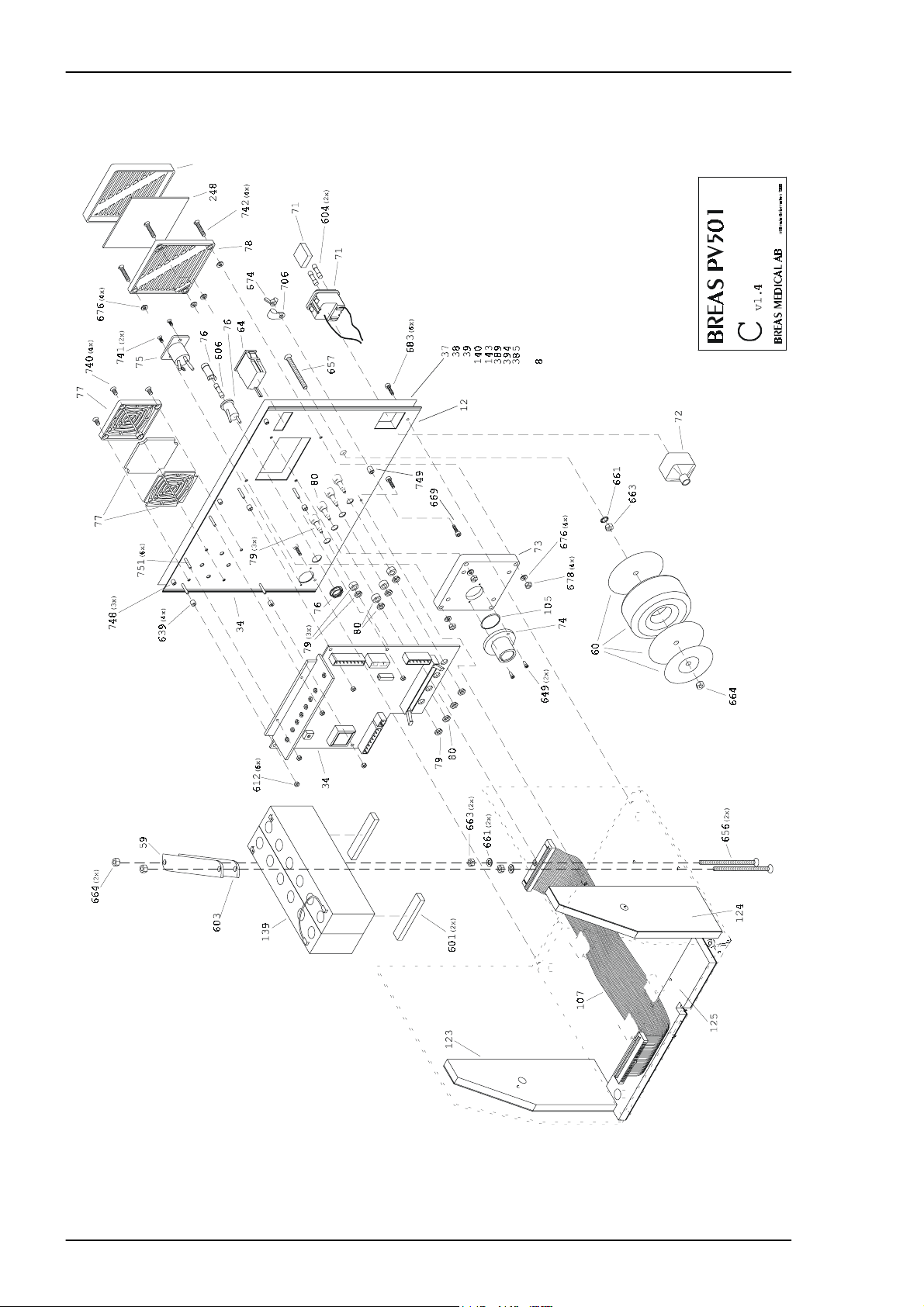
4.8 Exploded drawing, Hood Assembly 501
∂ρ#ελλερ
4 – 8 BREAS MEDICAL Doc. No.: 1523EN Issue: N-1
Page 24
Service Manual PV 501/501-2 REPLACEMENT PARTS
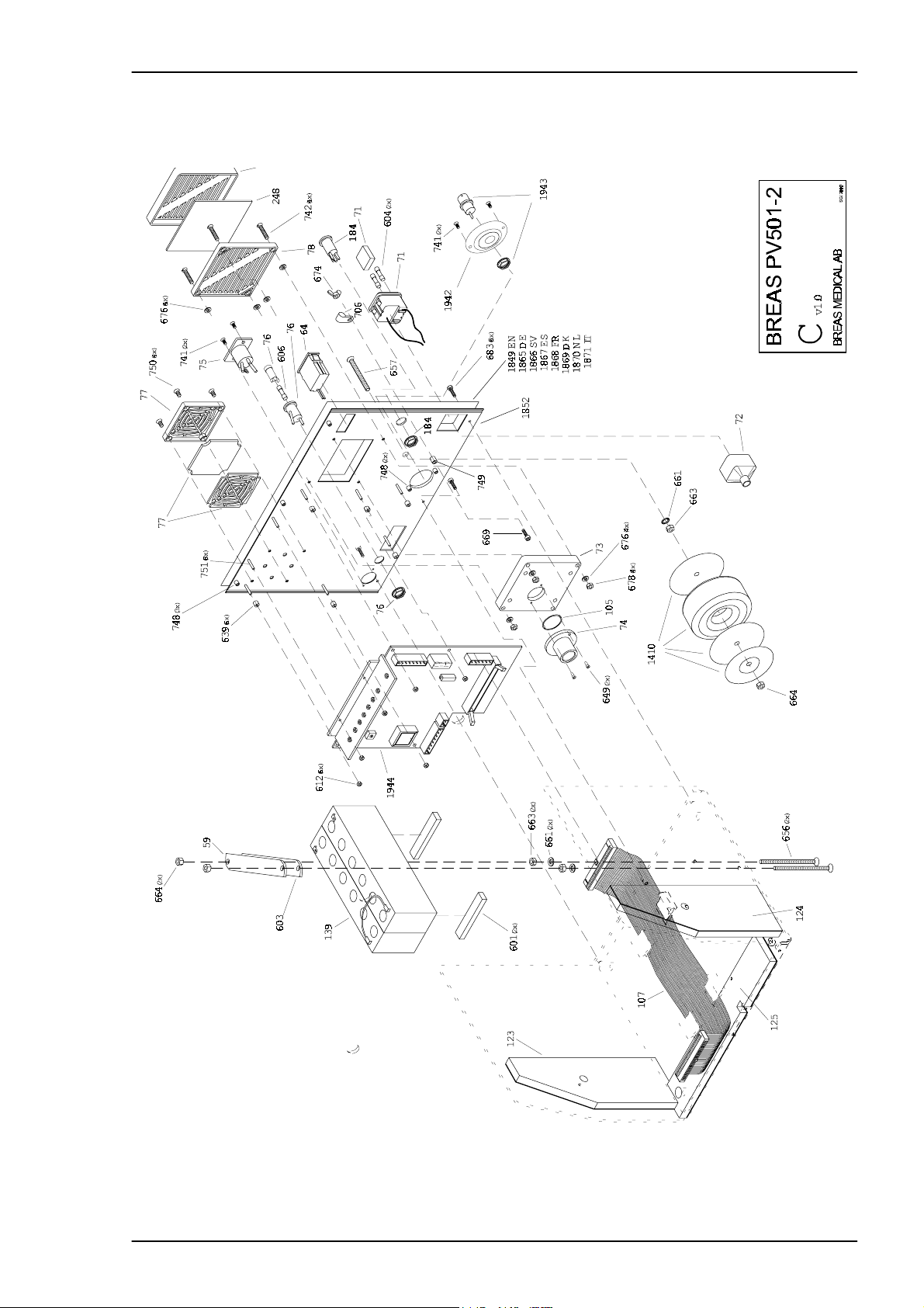
4.9 Exploded drawing, Hood Assembly 501-2
Doc. No.: 1523EN Issue: N-1 BREAS MEDICAL 4 – 9
Page 25

REPLACEMENT PARTS Service Manual PV 501/501-2
4.10 Part Number List
Part No. DescriptionNotes
2 Base plate, complete
4 Motor unit, Maxon - complete
5 Hood, complete, SE
6 Complete, Eng
7 Complete, Ger
8 Rear panel, complete, Eng
9 Rear panel, complete, Ger
10 Hood, complete, Eng
11 Hood, complete, Ger
12 Rear panel, blank
13 Potentiometer box
14 Magnet - potentiometer box
15 Air-hose connection - patient exhale
17 Side unit - motor bracket
18 Motor plate
19 Rear panel - Swedish text
20 Hood
21 Bottom plate
22 Angle bracket - front / hood
24 Cooler angle element
25 Angle bracket - reading prong (l imit position)
26 Ball screw - complete
27 Motor bracket
29 Panel - potentiometer panel Swedish text
30 Panel - patient air Swedish text
31 Rubber mount, shock absorbing (opto-switch)
32 Pressure sensor
33 Circuit board - CPU, PV501
34 Circuit board- MDA, PV501
35 Circuit board- potentiometer board
36 Battery Ni/Cd or Ni/Mh alarm back-up
44 Decal - "PATIENT PRESSURE"
45 Decal - "ON / OFF"
50 Cylomer - G12
51 Cable marking - plus
52 Cable marking - minus
53 Transf ormer - 115V
54 Opening - front
55 Cross bar
56 Spacing- motor bracket
57 Software
4 – 10 BREAS MEDICAL Doc. No.: 1523EN Issue: N-1
Page 26

Service Manual PV 501/501-2 REPLACEMENT PARTS
58 Battery - large 24 V lead
64 Hour counter - 24V
65 Flexible tube - inlet (2.5")
66 WAGO - 6-pole angled
67 WAGO - 2-pole angled
68 Reference pressure - valve
70 Reference pressure - reducer sleeve
71 Mains inlet
72 Touch protection
73 Air-filter box
74 Air-hose connection - inhale
75 Chassis pinning device XLR
76 Fuse holder
77 Screen guard - 60x60
78 Filter holder
79 Contact housing - black
80 Contact housing - red
82 Marking point - black
83 Marking point - red
84 Motor
85 Motor connection
86 Angle bracket- reading prong (column plate)
87 Air-hose connection - drive pack
88 Bellows side unit - fixed
89 Angle element - limit position (plastic)
90 Non-return valve
91 Opto switch - limit position
92 Opto switch - column plate
93 Column plate
94 Bellows
95 WAGO - 8-pole angled
96 Nipple - LCN-M5-PK3
97 O-ring - air-hose connection drive pack
98 Bellows side unit - moveable
99 Nipple - SCN-M10-PK4
100 Guide - large
101 Guide - small
102 Push-button board - on / off
103 Push-button board - battery test
104 Scale - graduated
105 O-ring - air-hose connection inlet
106 Panel - potentiometer panel English text
107 Ribbon cable
108 Instrument
Doc. No.: 1523EN Issue: N-1 BREAS MEDICAL 4 – 11
Page 27

REPLACEMENT PARTS Service Manual PV 501/501-2
109 Magnetic valve
110 Cyl, isolator
111 Decal - "ON / OFF"
112 Decal - "PATIENT PRESSURE"
113 Flexible tube - out (5")
114 Angle pipe - out
115 Pivot
116 Arrow - large guide
117 Arrow - small guide
118 Cover - large guide
119 Cover - small guide
121 Nipple - CN-M5-PK3
122 Rear panel - English text
123 Insulation - side unit left
124 Insulation - side unit right
125 Insulation - bottom
126 Insulation - hood
127 Panel - patient air English text
128 Mains cable
130 Packing - bellows side unit
134 Decal - "EIN / AUS"
135 Decal - "BEATMUNGSDRÜCK"
136 Rear panel - German text
137 Panel - potentiometer panel German text
138 Panel - patient air German text
139 Battery pack, complete
140 Text plate (IT)
141 Panel, pot. panel (IT)
142 Panel, patient air (IT)
143 Text plate (SP)
144 Panel, pot. panel (SP)
145 Panel, patient air (SP)
146 End cover for motor console, new version
147 Motor console, new version
148 Motor coupling, Rotex
149 Bellows end cover fixed, new version
150 Bellows end cover moving, new version
156 Spacer sleeve, moving end cover
157 Opto-switch, Optek
158 Seal
160 Shrink tubing - end position
184 115/230 switch, PV501-2
215 Rubber foot
220 Hook - WAGO-terminal block
4 – 12 BREAS MEDICAL Doc. No.: 1523EN Issue: N-1
Page 28

Service Manual PV 501/501-2 REPLACEMENT PARTS
248 Filter, air (5 pcs/packet)
287 Patient circuit (L-C)
378 Motor (BEI)
381 Decal "Pression de service" Fr
382 Decal "Reglage/Arret" Fr
383 Panel, pot. panel (Fr)
384 Panel, patient air (Fr)
385 Text plate (Fr)
386 Decal "PATIENTTRYK" DK
387 Decal "TIL/FRA" DK
388 Panel, pot. panel (Dk)
389 Text plate (DK)
390 Decal "PATIENT DRUK" NL
391 Decal "TIL/FRA" NL
392 Panel, pot. panel (NL)
393 Panel, patient air (NL)
394 Text plate (NL)
395 Bearing sleeve (PUR drive screw)
396 Bearing sleeve for bearing (drive screw)
397 Flange (PUR drive package)'
398 Flange (drive package)
458 Membrane, check valve
515 Serial No. decal with EAN code
516 Filter for machine ventilation
600 Tape - potentiometer box
601 Cellular rubber border
602 Air-hose 4 x 6 - frosted
604 Fuse TT 315mA
605 Fuse - T160mA
606 Fuse - F3,15A
611 M3 x 8 with washer
612 M3 - tooth nut
613 Heat conducting paste - HTC10S
614 Shrink tubing - 6.4 mm
615 Shrink tubing- 3.2 mm
616 Shrink tubing - 2.4 mm
617 Shrink tubing - 12.7 mm
618 Shrink tubing- 1.6 mm
632 Clips for ribbon cable
633 Strain relief - 4 mm
634 Strain relief - 3.5 mm
635 Cable tie brace
636 Cable tie- 8"
637 Cable tie- 4"
Doc. No.: 1523EN Issue: N-1 BREAS MEDICAL 4 – 13
Page 29

REPLACEMENT PARTS Service Manual PV 501/501-2
638 Cable tie- 14"
639 5 mm plate spacing
640 Y-connection
641 Blue Festo tubing
642 Mains cable straps
643 Black screw 201 - RXS 3.5 x 19
644 Clear tubing 9 x 12
645 Clear tubing 4 x 7
646 Clear tubing 3 x 6
647 Clear tubing 3 x 5
648 SPAX 4 x 20
649 SPAX 3 x 12
650 SGA 22
651 Seeger - AK-26 , or Sgh 32
652 M6 x 25 - bolt
653 M6 x 22 - washer
654 M6 - flat washer
655 M6 - locking nut
656 M5 x 80 F
657 M5 x 50 F
658 M5 x 20 socket head cap screw
659 M5 x 16 F
660 M5 x 16
661 M5 - toothed plate connector
662 M5 - flat washer
663 M5 - nut
664 M5 - locking nut
665 M4 x 8 F
666 M4 x 8
667 M4 x 45
668 M4 x 30
669 M4 x 20
670 M4 x 16 F
671 M4 x 16
672 M4 x 12
673 M4 x 10 F
674 M4 - wing nut
675 M4 - toothed plate connector
676 M4 - flat washer
677 M4 - nut
678 M4 - locking nut
679 M3 x 8
680 M3 x 6 F
681 M3 x 6
4 – 14 BREAS MEDICAL Doc. No.: 1523EN Issue: N-1
Page 30

Service Manual PV 501/501-2 REPLACEMENT PARTS
682 M3 x 16 F
683 M3 x 12 black socket head cap screw
684 M3 x 12
685 M3 x 10 F
686 M3 x 10
687 M3 - toothed plate connector
688 M3 - flat plate
689 M3 - nut
690 M3 - threaded bar
691 M2 x 10
692 M10 - toothed plate connector
693 KFXS 2.9 x 9.5 F
694 Fibre washer
699 Hook - for WAGO-terminal block
700 Packing - battery base
701 Plastic spacing - 4 x 15
702 Plastic spacing - 4 x 10
703 Plastic spacing - 3 x 10
704 Blind plug - angle bracket hole
705 Double-sided tape
706 Mains cable discharger
708 O-ring - potentiometer board
709 Fuse - 1.25 A
711 Cable tie - mini
713 M4 x 6 socket head cap screw
714 IC - MDA
716 Pressure sensor
723 Magnetic strip (0.01 m)
727 Cable tie, driller
740 Screw MFZ steel M4*10 Black, chrome Poz
741 M3 x 6 F - black, PV501-2
753 O-ring, check valve
795 Metal cable tie
796 Washer, support washer (drive unit)
797 Sliding bearing sleeve (drive unit)
798 Sliding bearing sleeve (PUR drive unit)
799 Spacer sleeve (drive unit)
800 Seal (drive unit)
1141 Drive unit complete (BEI)
1145 Rubber washer for transformer
1146 Metal washer for transformer
1410 Transformer, PV501-2
1636 Opening front, PV501-2
1720 Lock/keys, PV501-2
Doc. No.: 1523EN Issue: N-1 BREAS MEDICAL 4 – 15
Page 31

REPLACEMENT PARTS Service Manual PV 501/501-2
1850 Panel - potentiometer panel English text, PV501-2
1851 Scale for manometer 0-60mbar, PV501-2
1852 Rear panel plate, PV501-2
1858 Panel - potentiometer panel German text, PV501-2
1859 Panel - potentiometer panel Swedish text, PV501-2
1860 Panel - potentiometer panel Spanish text, PV501-2
1861 Panel - potentiometer panel French text, PV501-2
1862 Panel - potentiometer panel Danish text, PV501-2
1863 Panel - potentiometer panel Dutch text, PV501-2
1864 Panel - potentiometer panel Italian text, PV501-2
1865 Text plate German, PV501-2
1866 Text plate Swedish, PV501-2
1867 Text plate Spanish, PV501-2
1868 Text plate French, PV501-2
1869 Text plate Danish, PV501-2
1870 Text plate Dutch, PV501-2
1871 Text plate Italian, PV501-2
1942 Mount for BNC, PV501-2
1943 BNC connector, PV501-2
1944 Circuit board - MDA, PV501-2
2220 Circuit board - CPU, PV501-2
4 – 16 BREAS MEDICAL Doc. No.: 1523EN Issue: N-1
Page 32

Service Manual PV 501/501-2 FUNCTIONAL DIAGRAMS
5 FUNCTIONAL DIAGRAMS
5.1 Pneumatic diagram
1
2
RED
3
BLUE
GREEN
1. Check valves
2. Air intake for patient air
3. Magnetic valve: normally powered, see fig. 1.
4. Control pressure for the exhalation valve
5. Patient air outlet
6. Air intake for ambient air pressure
TRANSPARENT
4
5
6
7
8
7. Magnetic valve: normally not powered see fig. 2.
8. Pressure sensor
Doc. No.: 1523EN Issue: N-1 BREAS MEDICAL 5 – 1
Page 33

FUNCTIONAL DIAGRAMS Service Manual PV 501/501-2
5.2 Functional block diagram
5 – 2 BREAS MEDICAL Doc. No.: 1523EN Issue: N-1
Page 34

Service Manual PV 501/501-2 DISMANTLING AND ASSEMBLING THE PV 501/PV501-2
6 DISMANTLING AND ASSEMBLING THE PV 501/PV501-2
6.1 Opening the hood
• Remove the mains power cable.
• Loosen the three screws at the top of the rear panel and the three screws at the
front, see figure below.
ENTREE AIR PATIENTTEMPS UTILISATION
Changer après 500 heures de
fonctionnement ou quand nécess aire.
Afin d'autoriser la ch arge des batteries int ernes,
le PV 501 doit rester branché sur courant secteur au
moins 24 heures par mois.
NÄT
SÄKRING
T 315 mAL
PERSONVENTILATOR
NC
MAX 24 V. 1A
TRYCKALARM
0,1V/cm H O
REFROIDISSEMENT MACHINE
SÄKRING
F3.15 AL
2
EXT.BATTERI
24 VDC
DRIFT
NÄT/LADDNING
EXTERNT BATTERI
INTERNT BATTERI
TRIGGER
Från
Från
FrånFrån
TRIGGER
cm HO
2
LÅGT TRYCK
HÖGT TRYCK I/ E FREKVENS
cm HO
cm HO
cm HO
cm HOcm HO
2222
cm HOcm HO
2222
Förhållande
Förhållande
FörhållandeFörhållande
LÅGT TRYCK
HÖGT TRYCK
LÅG BATTERINIVÅ
FUNKTIONSFEL
TIDALVOLYM
Liter
Andetag/minut
Andetag/minutcm HO
Andetag/minutAndetag/minut
Felinställd
Felinställd
FelinställdFelinställd
PATIEN TTRY CKALARM
PATIENT-
DRIFT
LUFT
TILL
FRÅN
EXP.-
VENTIL
Fig. 6-1 The screw positions that hold the hood
• Lift the hood slightl y upwards at t he rear so that t he a ngled par t of the hood cle ars
the rear panel. Move the hood forward approx. 20 mm and angle the hood up. Disconnect the hose from the patient air outlet.
Fig. 6-2 Opening the hood
• Lay the hood down flat against the work surf ace. It is not necessary to loosen the
other tubes and cables to the front panel.
• Disconnect the white patient inlet air hose from the end cover of the bellows.
Doc. No.: 1523EN Issue: N-1 BREAS MEDICAL 6 – 1
Page 35

DISMANTLING AND ASSEMBLING THE PV 501/PV501-2 Service Manual PV 501/501-2
6.2 Replacing pushbutton boards
• Disconnect the ribbon cable (1) from the CPU board.
• Cut the cable tie (2) holding the green air tube (see figur e).
• Remove the four nuts that hold the t wo boards (indicated by ar rows) and move the
black ground wire terminal (3) to one side.
• Install the new boards in the reverse order.
1
J1
2
3
Fig. 6-3 Removing the On/Off board
Installing a new ON/OFF board with 2 sec delay in units with a Serial No.
lower than 5925
Connect a wire from new board to J1.
Place “ON/OFF 2 sec delay” sticker above on/off switches on PV501.
NOTE! Disregard the text "CUT WIRE WHEN USING CABLE WITH CPU-CARD
REV.B OR OLDER" on the On/Off board. Do not cut any wire on the On/Off
board if it is Rev C.
6 – 2 BREAS MEDICAL Doc. No.: 1523EN Issue: N-1
Page 36

Service Manual PV 501/501-2 DISMANTLING AND ASSEMBLING THE PV 501/PV501-2
6.3 Replacing the CPU board
• Disconnect the three ribbon cable connectors (indicated by arrows in the figure
below).
Fig. 6-4 Removing the CPU board
• Disconnect the air hose from the magnetic val ve. NOTE! Exercise care. Do not
pull too hard towards the valve without providing a counterhold for the valve. It
may be better to cut the hose.
• Disconnect the lower hose from the Y-connector.
Fig. 6-5 Removing the CPU board
• Unscrew the 6 nuts that hold the board.
Doc. No.: 1523EN Issue: N-1 BREAS MEDICAL 6 – 3
Page 37

DISMANTLING AND ASSEMBLING THE PV 501/PV501-2 Service Manual PV 501/501-2
Fig. 6-6 Removing the CPU board
• Lift out the board.
• Reassemble in reverse order.
6.4 Replacing the potentiometer board
• Remove the six setting knobs by first removing the plastic cap for the knob and
then, for the two large knobs unscrew their retaining nuts, and for the smaller
knobs unscrew the screws.
AC/CHARGING
EXTERNAL BATTERY
INTERNAL BATTERY
TRIGGER
Off
Off
OffOff
LOW PRESSURE
cm HO
cm HOcm HO
2222
POWER
TRIGGER
cm H O
2
HIGH PRESSURE
cm HO
cm HO
cm HOcm HO
LOW PRESSURE
HIGH PRESSURE
LOW BATTERY
FUNCTION FAILURE
TIDAL VOLU ME
Signal
Signal
SignalSignal
2222
Litre
I/E BREATH RATE
Ratio
Ratio
RatioRatio
Setting error
Setting error
Setting errorSetting error
BPM
BPMcm HO
BPMBPM
PATIENT PRESSUREALARMS
EXHALATION
VALVE
PATIEN T
AIR
Fig. 6-7 Removing the setting knobs
• Disconnect the ribbon cable from the CPU board.
• Disconnect both the air tubes from the magnetic valve.
POWER
ON
OFF
Fig. 6-8 Removing the Potentiometer board
• Unscrew the 4 nuts holding the board.
6 – 4 BREAS MEDICAL Doc. No.: 1523EN Issue: N-1
Page 38

Service Manual PV 501/501-2 DISMANTLING AND ASSEMBLING THE PV 501/PV501-2
Fig. 6-9 Removing the Potentiometer board
• Lift out the board.
• Reassemble in the reverse order.
6.5 Opening the rear panel
• Open the hood, if not already opened.
• Remove the three screws at the bottom of the rear panel and carefully lower it
down onto the work surface.
• Release the two securing locks for the ribbon cable connector and disconnect it.
• Disconnect the air inlet h ose from the motor unit.
Fig. 6-10 Opening the rear panel
• To remove the cross bar for the side panel s, first pull it up a little and then turn it so
that the slots disengage. Loosen the rod from one side panel at a time.
6.6 Replacing the MDA board
• Open the hood and rear panel.
• Disconnect the CN6, CN7, CN8, CN9, CN10 connectors.
Doc. No.: 1523EN Issue: N-1 BREAS MEDICAL 6 – 5
Page 39

DISMANTLING AND ASSEMBLING THE PV 501/PV501-2 Service Manual PV 501/501-2
Fig. 6-11 Removing the MDA board
• Unscrew the 6 M3 and the 4 M8(on PV501) nuts while holding the board.
Fig. 6-12 Removing the MDA board
• Lift out the board.
• Reassemble in reverse order.
6.7 Removing the motor unit
• Open the hood and rear panel.
(only PV501)
6 – 6 BREAS MEDICAL Doc. No.: 1523EN Issue: N-1
Page 40

Service Manual PV 501/501-2 DISMANTLING AND ASSEMBLING THE PV 501/PV501-2
12
Fig. 6-13 Removing the motor unit
• Remove the cross bar (1 in figure).
• Disconnect the air hoses from the bellows end cover.
• Loosen the encoder c able connecto r (2) from the MDA circuit board inside the rear
panel.
• Loosen the motor cable connector (3) from the MDA circu it board inside the rear
panel.
• Disconnect the red tube (4) to the exhalation valve on the motor unit.
• Loosen the four nuts (M4) ( indicated by the four bol d arrows in the figu re) from th e
motor unit's base plate.
• Lift the motor unit straight up.
6.8 Reassembling the motor unit
• Before reassembling the motor unit, check if the internal batteries need to be
replaced as this is best done with the motor unit removed, see 3.8. 13.
• Mount the motor unit and fasten it with the four nuts (M4) at the bottom of the
motor unit.
4
3
• Connect the encoder cable connector to the MDA circuit board.
• Connect the motor cable connector to the MDA circuit board.
• Connect the red tube to the exhalation valve on the motor unit.
• Start the ventilator.
• Check that everything functions normally.
6.9 Assembling the hood and rear panel
• Fit the cross bar between the side panels.
Doc. No.: 1523EN Issue: N-1 BREAS MEDICAL 6 – 7
Page 41

DISMANTLING AND ASSEMBLING THE PV 501/PV501-2 Service Manual PV 501/501-2
• Raise the rear panel and fasten it with the lower screws. Check that no cables or
hoses are pinched. Do not forget to connect the ribbon cable.
• Fit the air inlet hose between the rear panel and motor unit.
• Move the hood up so that the patient outlet ai r hose can be fit ted to the motor unit .
• Check that the ribbon cable does not lay against the bellows. If necessary , press
the ribbon cable down at the back and front.
• Insert the screws in the front panel but do not tighten yet.
• Tighten the top screws for the rear panel.
• Tighten the screws on the front panel at the same time as the hood is pressed
downwards.
• Check that everything is assembled correctly.
6 – 8 BREAS MEDICAL Doc. No.: 1523EN Issue: N-1
Page 42

Service Manual PV 501/501-2 MOTOR UNIT
7 MOTOR UNIT
7.1 Construction
123 4 5,6 7
18
17
16
15
14
13
8
9
12
Fig. 7-1 Main parts of the motor unit
Pos. No.
(1) Motor bracket spacer bar
(2) Angle element-limit position
(3) Bellows clamp (steel hose clamp)
(4) Bellows
(5) Patient air inlet, and check valve
(6) Patient air outlet, and check valve
(7) Motor
(8) Motor connection
(9) Air nipple
(10) Rubber suspension for ball bearings
(11) Ball bearings
(12) Motor bracket
(13) Ball screw complete with bearing
(14) Oil bronze bearing with rubber suspension
(15) Slotted disc
(16) Opto-switch (encoder)
(17) Opto-switch (limit position sensor)
(18) Side plate
Description
10,11
See also exploded diagrams in Chapter 4.
Doc. No.: 1523EN Issue: N-1 BREAS MEDICAL 7 – 1
Page 43

MOTOR UNIT Service Manual PV 501/501-2
7.2 Lubricating the ball screw
• Turn the ball screw with the fingers, this is easiest done at the screw/motor connection(1 in figure). Keep turning until the bellows is completely compressed.
• Wipe off the old grease from the ball screw (2) if necessary e.g. if it is dirty.
2
1
Fig. 7-2 Lubricating the ball screw
• Apply a thin layer of grease over the entire length of the screw. Use only BREAS
grease type 283 AZ, part no. 000 557.
• Run the motor a couple of cycles to work the grease into the unit. Remove any
excess grease.
• If necessary, repeat greasing once more.
7 – 2 BREAS MEDICAL Doc. No.: 1523EN Issue: N-1
Page 44

Service Manual PV 501/501-2 MOTOR UNIT
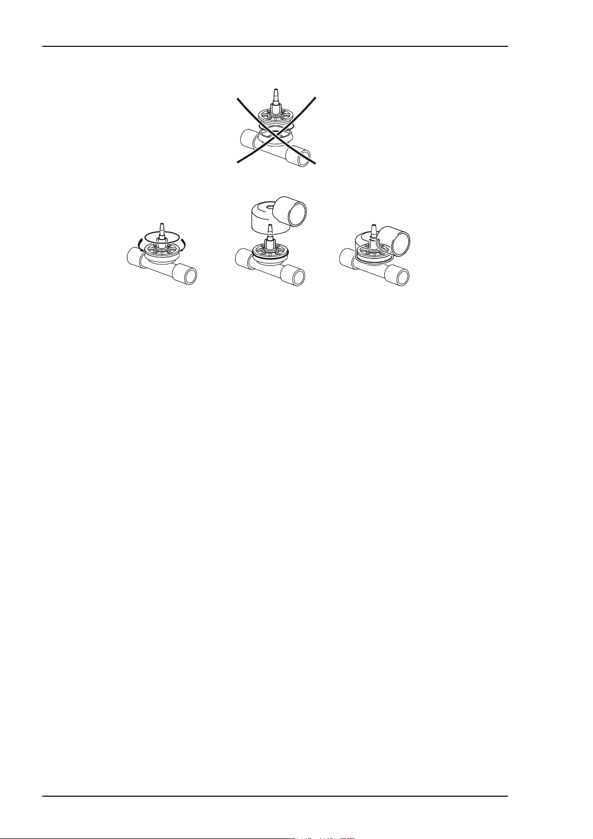
7.3 Replacing the membranes in the check valves
• The membranes must be changed at each maintenance service.
Material required:
Service kit for check valves part. no: 002 123, which contains: 2 membranes and
2 O-rings.
3
3
(8x)
2
1
1
Fig. 7-3 Replacing the check valves
• Remove the hoses (1).
• Remove the four screws (2) (M3x8) holding each hose connection.
• Remove the old membranes together with the valve seats and O-rings (3).
• Wipe the valve seats in the end cover clean using a damp cloth.
• Carefully assemble the new membranes.
• Make sure that the new membranes lay flat against their seats.
• Fit new O-rings.
• Fit the hose connections.
• Check the function of the check valves by creating a negative pressure in the inlet
hose and a positive pressure in the outlet hose. No air should be able to pass. (Do
not forget to plug the tube connector for the exh. valve).
7.4 Hoses and bellows, leakage check
Check the function of the outlet check valves by creating a positive pressure in
the exhalation hose (do not forget to block the tube nipple).
Plug the hose for air outlet and the small tube connector. Create a pressure in the
inlet hose, approx. 40 cm H
for the pressure to drop from 40 to 20 cm H
not, check for leakage or replace the motor unit.
Doc. No.: 1523EN Issue: N-1 BREAS MEDICAL 7 – 3
O. Check that no leakage is heard. Measure the time
2
O, it should take at least 10 sec. If
2
Page 45

MOTOR UNIT Service Manual PV 501/501-2
7.5 Wiring diagram, Motor unit
8 POLE WAGO CONNECTOR
RED
BLACK
WHITE
BLACK
GP1L03
TO CN7 ON MDA BOARD
8-POLE WAGO CONNECTOR
OPB930W51
WHITE
BLUE
RED
BLACK
GREEN
MOTOR BEI
YELLOW
GRAY
ORANGE
BLUE
BROWN
GREEN
BLACK
RED
MOTOR MAXON
TO CN10 ON THE MDA BOARD
GREEN
BLUE
RED/GRAY
BLACK/GRAY
WHITE/GRAY
RED
BLACK
WHITE
8-POLIG WAGOKONTAKT
TILL CN10 PÅ MDA-KORTET
7 – 4 BREAS MEDICAL Doc. No.: 1523EN Issue: N-1
Page 46

Service Manual PV 501/501-2 MOTOR UNIT
Doc. No.: 1523EN Issue: N-1 BREAS MEDICAL 7 – 5
Page 47

MOTOR UNIT Service Manual PV 501/501-2
7 – 6 BREAS MEDICAL Doc. No.: 1523EN Issue: N-1
Page 48

Service Manual PV 501/501-2 MOTOR UNIT
Doc. No.: 1523EN Issue: N-1 BREAS MEDICAL 7 – 7
Page 49

Service Manual PV 501/501-2 ELECTRONICS
8 ELECTRONICS
8.1 Function, Construction
The electronics, mechanics, pneumatics and opto-electronics are fully integrated in the
PV 501/PV 501-2 ventilators.
To understand the function of the electronics included in the Breas PV 501 you must be
able to operate the ventilator, have studied the air flow diagram and acquainted yourself
with its mechanical construction.
The following block diagram (PV6T1) outlines how the electronic system is constructed
and how it is connected to the other components.
Fig. 8-1 Functional Diagram
Doc. No.: 1523EN Issue: N-1 BREAS MEDICAL 8 – 1
Page 50

ELECTRONICS Service Manual PV 501/501-2
8.2 PV 501/PV 501-2's circuit boards
The PV 501/PV 501-2’s electronics comprises 5 circuit boards:
2
3
4
1
Fig. 8-2 Location of the ciruit boards
Pos. No.
1 Pushbutton board “On/Off buttons”
1 Pushbutton board “Mute/Battery test buttons”
2 CPU board “front panel”
3 Pot. board “front inside opening”
4 MDA-board “rear panel”
Location:
8 – 2 BREAS MEDICAL Doc. No.: 1523EN Issue: N-1
Page 51

Service Manual PV 501/501-2 ELECTRONICS
8.3 Pushbutton board
Fig. 8-3 Pushbutton board
The membrane switches for ON, OFF, Alarm mute and Battery test are located on the
pushbutton board together with LEDs that indicate that the ventilator is switched ON and
that Alarm mute has been activated.
8.4 Potentiometer board
PZ1
Front view Rear view
Fig. 8-4 Potentiometer board
The potentiometers (P1 - P6) are located here. They are used for setting the volume, I/
E, frequency, trigger, high pressure, low pressure and alarm volume. The alarm buzzer
PZ1 is also located here, along with the MV2 magnet valve which is normally powered,
but switches if the high pressure alarm is activated. The exhalation valve then opens as
a safety precaution. See the air flow diagram.
MV2
Doc. No.: 1523EN Issue: N-1 BREAS MEDICAL 8 – 3
Page 52

ELECTRONICS Service Manual PV 501/501-2
8.5 MDA board
The MDA board handles the voltage supply, motor control and the charging of the internal battery.
R 120
U 32
F 1
R 127
Fig. 8-5 MDA board
The MDA board is supplied with 24 V AC via CN5 from the toroidal core transformer.
The current is rectified in B1 and supplies the voltage regulators U36 and U39 with voltage. At power on, the other regulators are supplied via the K2 relay.
The motor is a brushless DC motor. The U34 and U35 circuits produce current and voltage for the motor’s three windings causing it to rotate. The maximum motor current is
limited by R120. To keep track of the number of rotations and how fast the motor is running, a pulse sensor has been mounted on the ball screw, which is an extension of the
motor shaft. (The pulse sensor consists of a slotted disk with 96 slots and an optoswitch).
The U32 microprocessor receives information from the pulse sensor, and regulates the
velocity and the number of rotations the motor is running at. The home position of the
moving end of the bellows unit is also registered by U32 with the help of an opto-switch.
The internal batteries are connected to the MDA board. Fuse F1 protects these batter-
8 – 4 BREAS MEDICAL Doc. No.: 1523EN Issue: N-1
Page 53

Service Manual PV 501/501-2 ELECTRONICS
ies.
The internal battery (lead) charger consists of a voltage regulator U36, where the
charge voltage is regulated by R127 and a current limiter equipped with transistors Q25
and Q27. When the battery voltage drops below 22.7 V during operation, the low battery
level alarm is activated. If the battery level reaches 30 VDC, a thyristor connects the battery to ground until fuse F1 blows. This prevents the battery from creating explosive gas.
The ventilator stops and sounds an alarm when the voltage drops below 22.0 V and the
bi-stable relay K5 cuts out. The ventilator must then be connected to the mains in order
for K5 to switch back again, and for the batteries to recharge.
When the external battery voltage drops below 22.5 V during operation, the ventilator
switches over to internal battery power and gives a short warning alarm.
8.5.1 Checking the pressure transducer offset and gain
Connect a voltmeter to the pressure outlet on the rear panel, see Op. manual. Range: 02 VDC. Set the frequency to 9 breaths/min and start the ventilator. Wait approx. 10 min
for the pressure to stabilise. Adjust the offset between inhalations to 1,00-1,01 volt with
the trim pot R21 marked OFFS. Do not connect a "counter pressure" to the patient air
outlet. The trigger's offset reference automatically follows the adjustment of the pressure
transducers offset level in order to always calculate the adjustment of the trigger setting.
The R24 potentiometer is used to adjust the gain which should be 4.0 V at 30 mbar.
Note! If it was necessary to adjust the gain, then re-check the offset again.
R 21
R 24
Fig. 8-6 Adjusting the offset and gain
8.5.2 Checking the instrument accuracy
Check, using a manometer connected to the exh. valve connection, that the indicating
instrument gives the correct indication and that the needle moves "softly".
NOTE! Make small pressure changes, the indicating instrument should be
"slower" compared with the manometer.
Doc. No.: 1523EN Issue: N-1 BREAS MEDICAL 8 – 5
Page 54

ELECTRONICS Service Manual PV 501/501-2
8.6 CPU board
MV1
G1
BT1
BT2
R 21
R 24
U 3
U 6
Fig. 8-7 CPU board
The “master” microprocessor U3 and its software capsule EPROM U6 are located on
the CPU board together with the pressure gauge, the pressure sensor, the LEDs indicating the voltage source as well as the alarm, alarm battery and magnetic valve MV1.
U3 takes a reading from the potentiometers on the potentiometer board for frequency,
volume, I/E, trigger and alarm limits. It also reads the “alarm mute” button, patient pressure and the voltages for internal battery DC, external DC, alarm battery DC and the DC
generated by the mains voltage.
U3 then controls and monitors the ventilator including the LEDs at the front, the form of
breathing cycle and all the alarms. Besides the pressure and voltage monitoring alarms,
there is also a system for monitoring communication between U3 and U32, e.g. that
inhalation occurs within a specified time, and that failure to do so causes an alarm.
Many of these alarms come in the form of a combination of the LEDs in the front panel
lighting. For more information, see Chapter 9 Fault tracing.
The display instrument for patient pressure is a moving coil instrument. It operates quite
slowly (having a certain inertia) which means the display is slow to react when very fast
changes in pressure occur. When servicing and fault tracing it is advisable to use an
analogue manometer.
The G1 pressure sensor is a semiconductor and the signal emitted is amplified by U14.
The R24 potentiometer adjusts the amplification and R21 adjusts the offset.
The magnetic valve MV1 is used to connect the two outlets on the pressure sensor with
reference pressure outlet on the rear panel(or front panel from serial no 5204). When
the trigger is activated, a zero pressure calibration is implemented between each inhalation for the first five minutes, and then once every minute with the help of MV1. See the
pneumatic diagram.
The BT1 & BT2 alarm batteries are of the Ni/CD or Ni/Mh type and are monitored by U3.
If are dead or out of function, the ventilator would not start without sounding an alarm
and displaying an error code, see Chapter 9. The batteries are charged as soon as the
ventilator is connected to mains supply.
8 – 6 BREAS MEDICAL Doc. No.: 1523EN Issue: N-1
Page 55

Service Manual PV 501/501-2 ELECTRONICS
8.7 Terminal diagram, test points
Fig. 8-8 Test points
Doc. No.: 1523EN Issue: N-1 BREAS MEDICAL 8 – 7
Page 56

ELECTRONICS Service Manual PV 501/501-2
MDA board, PV 501
Tes t p oint Vo l t a g e n am e Status Measured value Adj. pot.
TP 1 GND
TP 2 Unregulated on 24-38 VDC –
TP 3 Int. Pb battery charge off, mains 28.2 VDC R127
TP 4 24 V on 24 VDC –
TP 5 12 V on 12 VDC –
TP 6 5 V on 5 VDC –
MDA board, PV 501-2
Tes t p oint Vo l t a g e n am e Status Measured value Adj. pot.
TC 1:1 Internal battery raw 28V –
TC 1:2 Int. Pb battery charge off, mains 28.2 VDC –
TC 1:3 DC transf. after relay K6 on 30-40 VDC –
TC 1:4 DC transf. before relay K6 on 30-40 VDC –
TC 1:5 Over current limit on 0-7 VDC –
TC 1:6 24 V stab (+24) on 24 VDC –
TC 1:7 Ground via 10k pressure - on 0 VDC –
TC 1:8 Pressure + on 0-8 VDC –
TC 1:9 Direction motor on 0-5 VDC –
TC 1:10 Alarm relay on 0-24 VDC –
TC 1:11 Encoder signal (count) on 0-5 VDC –
TC 1:12 Homeposition motorunit on 0-5 VDC –
TC 1:13 5 V stab (+5s) on 5 VDC –
TC 1:14 External battery (Extdc) on 24 VDC –
TC 1:15 Gnd – – –
TC 1:16 Gnd – – –
8 – 8 BREAS MEDICAL Doc. No.: 1523EN Issue: N-1
Page 57

Service Manual PV 501/501-2 ELECTRONICS
CPU board, PV 501/PV501-2
Test point Vo ltage nam e Status Measured value Adj. pot.
TP 7 GND
TP 8 9 V on 9 VDC –
TP 9 Alarm battery off,mains 8.2 VDC –
off, no mains 7 –
TP 10 5 V on 5 VDC –
TP 11 Pressure amplifier on P=0 mbar 1.0 VDC R21, (R24)
P=30 mbar 4.0 VDC
Doc. No.: 1523EN Issue: N-1 BREAS MEDICAL 8 – 9
Page 58

ELECTRONICS Service Manual PV 501/501-2
8.8 Measuring points on the motor unit
The motor unit’s electronic components consists of a motor and two opto-switches.
OPB930W51
Fig. 8-9 Measuring points on the motor unit
The above diagram shows how the function of the opto-switch can be measured.
Opto-switch limit Connect a DMM (digital multi meter) between pins 3 &
4.
Start the ventilator.
At limit position: approx. 5 V
Non limit position: approx. 0.7 V
Opto-switch pulse sensor Connect an oscilloscope between pins 6 & 8 on PV 501
or on TC1 between pin 11 & 16 on PV 501-2.
Set the ventilator as follows:
Tidal volume: 1.2 l
Frequency: 12
I/E 1:2
Trigger -1
Set the oscilloscope to 1 V/div. and 0.2 ms/div.
Start the ventilator.
8 – 10 BREAS MEDICAL Doc. No.: 1523EN Issue: N-1
Page 59

Service Manual PV 501/501-2 ELECTRONICS
8.9 Internal Battery test
The batteries should be fully charged or charged for at least 12 hours with the ventilator
turned off before this test is carried out. The batteries, when fully charged, should operate the PV 501/501-2 for at least 2 hours, if not the batteries must be replaced.
Adjust the settings to: Tidal volume: 0,8L
Frequency: 14
I/E: 1:2
Connect a 1 litre test lung to the exhalation valve.
Note the time on the running time meter.
Turn the ventilator on, check that the LED for "Internal battery" is flashing.
If necessary adjust the tidal volume to allow the patient pressure to reach approx.
20 cm H
Let the ventilator run until the battery charge drops too low. Check that alarm for "Low
battery level" is given for 15 minutes before the ventilator switches off.
Check that the alarm continues to sound 5 minutes after the ventilator has switched off.
O.
2
With the ventilator turned off, charge the battery for at least 12 hours. Check that the
batteries are fully charged by pressing "Batt. test" (with the ventilator running and the
mains disconnected). The needle should indicate in the upper part of the green sector.
8.10 Replacing the internal power batteries (lead acid cells)
The internal power batteries must be replaced:
– If the ventilator is often run from the internal batteries, they should be replaced
every 24 months or when required.
– If the batteries, when fully charged, fail to run the ventilator for at least 2 hours.
• Remove the motor unit by loosening the four nuts holding the base plate.
• Disconnect the connector to the encoders on the rear panel.
• Loosen the motor cable connector.
• Loosen the thin red tube for the exhalation valve.
• Lift the motor unit straight up.
• Remove the two nuts for the battery fastening bar. Only disconnect the two cables
from the battery that are connected to the circuit board.
• Lift out the batteries.
• Install the new batteries in place and the fastening bar.
• Connect the wires from the circuit board.
• Install the motor unit.
• Make a test start and check that everything appears to function normally. Turn off
the ventilator.
• Charge the batteries for at least 12 hours and then perform a battery test, see
Section 8.9.
Doc. No.: 1523EN Issue: N-1 BREAS MEDICAL 8 – 11
Page 60

ELECTRONICS Service Manual PV 501/501-2
8.11 Replacing the alarm batteries (Ni-Cd)
The alarm batteries are contained on the CPU board in the hood (see figure). The internal batteries normally provide power for the alarm function, but should they become discharged, the alarm battery will provide back-up power. The alarm battery must be
replaced every 5th year counted from date of delivery or when it was last replaced.
Alarm batteries
BT1
BT2
Fig. 8-10 Replacing the alarm batteries
To replace the alarm batteries:
• Open the connector locks and disconnect the three ribbon cables from the CPU
board.
• Mark the hoses A, B and C using a marker pen, then disconnect these.
• Remove the five nuts that hold the board.
• Remove the board.
• Cut the two "pins" on battery marked "Y", closest to the edge board. Unsolder the
"Y"-battery from the minus pole.
• Cut the other battery pin.
• Remove the old battery pins.
• Assemble the new batteries and solder these in place.
• Reassemble the circuit board, hoses, cable ties and ribbon cables.
• Make a test start. PV 501 checks at each start cycle the condition of the alarm batteries. If there is a fault with the alarm battery, the ventilator will not start and the
LEDs for "FUNCTION FAULT" and "TRIGGER" will light. If this happens after
replacing the battery, let the ventilator remain connected to the mains for a few
hours for the battery to be charged. Thereafter, make a new test start.
8 – 12 BREAS MEDICAL Doc. No.: 1523EN Issue: N-1
Page 61

Service Manual PV 501/501-2 ELECTRONICS
8.12 Electrical safety
Electrical safety measurements should be performed according to IEC 601, but the isolation resistance can be measured instead of the current test as according to the stipulated requirements in the standard.
The measurements can be performed with an automatic electricity safety tester. All tests
shall be performed according to class II type BF.
8.12.1 Mains
Register the mains value. As the current is directly dependant of the mains outlet being
used it is necessary to register the mains at each maintenance. This allows values registered from the same machine to be compared at different occasions.
8.12.2 Isolation
The isolation resistance is measured with 500 VDC current source. Preferably, the plus
is connected to both mains pins and minus to the exterior or patient connections. The
measurement performed at the delivery check gives the reference value that maintenance measurements are compared with. If this has not be done, the value of the isolation resistance should be > 20M .
8.12.3 Leakage current
Leakage current is registered from various parts of the machine through a RC-circuit to
earth. Measurements are made in normal cases (NC) and at single fault condition
(SFC). Reverse voltage polarity mains and note the lowest value.
Leakage to the earth should not exceed the stated limit value.
8.12.4 Leakage current from the cabinet
Leakage current from the cabinet.
Measure at an unvarnished part, i.e. a screw head.
Limit value: NC < 0,1mA
SFC < 0,5mA
Break neutral for SFC.
8.12.5 Patient leakage
Measured between patient connection and earth.
Limit value: NC. < 0,1mA
SFC. < 0,5mA
Break neutral for SFC.
8.12.6 Leakage current at mains voltage at patient connected part
This test should only be performed with the automatic electrical safety tester. See the
testing security instruction.
Limit value: SFC. < 5mA
Doc. No.: 1523EN Issue: N-1 BREAS MEDICAL 8 – 13
Page 62

ELECTRONICS Service Manual PV 501/501-2
8.13 Wiring Diagrams PV 501/501-2
8 – 14 BREAS MEDICAL Doc. No.: 1523EN Issue: N-1
Page 63

Service Manual PV 501/501-2 ELECTRONICS
Doc. No.: 1523EN Issue: N-1 BREAS MEDICAL 8 – 15
Page 64

ELECTRONICS Service Manual PV 501/501-2
8 – 16 BREAS MEDICAL Doc. No.: 1523EN Issue: N-1
Page 65

Service Manual PV 501/501-2 ELECTRONICS
Doc. No.: 1523EN Issue: N-1 BREAS MEDICAL 8 – 17
Page 66

ELECTRONICS Service Manual PV 501/501-2
8 – 18 BREAS MEDICAL Doc. No.: 1523EN Issue: N-1
Page 67

Service Manual PV 501/501-2 ELECTRONICS
Doc. No.: 1523EN Issue: N-1 BREAS MEDICAL 8 – 19
Page 68

ELECTRONICS Service Manual PV 501/501-2
8 – 20 BREAS MEDICAL Doc. No.: 1523EN Issue: N-1
Page 69

Service Manual PV 501/501-2 ELECTRONICS
PV 501-2
Doc. No.: 1523EN Issue: N-1 BREAS MEDICAL 8 – 21
Page 70

ELECTRONICS Service Manual PV 501/501-2
8 – 22 BREAS MEDICAL Doc. No.: 1523EN Issue: N-1
Page 71

Service Manual PV 501/501-2 ELECTRONICS
Doc. No.: 1523EN Issue: N-1 BREAS MEDICAL 8 – 23
Page 72

ELECTRONICS Service Manual PV 501/501-2
8 – 24 BREAS MEDICAL Doc. No.: 1523EN Issue: N-1
Page 73

Service Manual PV 501/501-2 ELECTRONICS
Doc. No.: 1523EN Issue: N-1 BREAS MEDICAL 8 – 25
Page 74

ELECTRONICS Service Manual PV 501/501-2
8 – 26 BREAS MEDICAL Doc. No.: 1523EN Issue: N-1
Page 75

Service Manual PV 501/501-2 ELECTRONICS
Doc. No.: 1523EN Issue: N-1 BREAS MEDICAL 8 – 27
Page 76

ELECTRONICS Service Manual PV 501/501-2
8 – 28 BREAS MEDICAL Doc. No.: 1523EN Issue: N-1
Page 77

Service Manual PV 501/501-2 ELECTRONICS
Doc. No.: 1523EN Issue: N-1 BREAS MEDICAL 8 – 29
Page 78

ELECTRONICS Service Manual PV 501/501-2
8.14 Functional block diagram PV6 T1
8 – 30 BREAS MEDICAL Doc. No.: 1523EN Issue: N-1
Page 79

Service Manual PV 501/501-2 ELECTRONICS
8.15 COMPONENT LOCATION DRAWINGS PV 501
8.15.1 Pushbutton Boards PV 501, Versions B & E
8.15.2 Potentiometer Board PV 501
Doc. No.: 1523EN Issue: N-1 BREAS MEDICAL 8 – 31
Page 80

ELECTRONICS Service Manual PV 501/501-2
8.15.3 CPU Boards PV 501, Version B & E
8 – 32 BREAS MEDICAL Doc. No.: 1523EN Issue: N-1
Page 81

Service Manual PV 501/501-2 ELECTRONICS
8.15.4 MDA Boards PV 501
Doc. No.: 1523EN Issue: N-1 BREAS MEDICAL 8 – 33
Page 82

ELECTRONICS Service Manual PV 501/501-2
8 – 34 BREAS MEDICAL Doc. No.: 1523EN Issue: N-1
Page 83

Service Manual PV 501/501-2 ELECTRONICS
8.16 COMPONENT LOCATION DRAWINGS PV 501-2
8.16.1 Pushbutton Boards PV 501-2
SW Rev. F
Doc. No.: 1523EN Issue: N-1 BREAS MEDICAL 8 – 35
Page 84

ELECTRONICS Service Manual PV 501/501-2
8.16.2 Potentiometer Board PV 501-2
Rev. XA
Rev F
8 – 36 BREAS MEDICAL Doc. No.: 1523EN Issue: N-1
Page 85

Service Manual PV 501/501-2 ELECTRONICS
8.16.3 CPU Boards PV 501-2
Rev. XA
Rev. F
Doc. No.: 1523EN Issue: N-1 BREAS MEDICAL 8 – 37
Page 86

ELECTRONICS Service Manual PV 501/501-2
8.16.4 MDA Boards PV 501-2 XA
8 – 38 BREAS MEDICAL Doc. No.: 1523EN Issue: N-1
Page 87

Service Manual PV 501/501-2 ELECTRONICS
8.17 List of components PV 501
R1,R70 3M9 0.25W
R2 8x10k SIL 9PIN/BRESISTOR
R3 1k 0.25W
R4 100 0.25W
R5 27k 0.25W
R6 2k2 0.25W
R7-R13,R15 1k8 0.25W
R14 2k2 0.25W
R16 4k7 0.4W
R17,R19 180 0.25W
R18 390 0.25W
R20 4x33k SIL 8PIN/4RESISTOR
R21,R28,R33 100k 15T TRIMBOURNS 3006P
R22,R23 1M 0.25W
R24 20k 15T TRIMBOURNS 3006P
R25,R36 4x100k SIL 8PIN/4RESISTOR
R26,R27 10k 1% 0.25W
R29 4x10k SIL 8PIN/4RESISTOR
R30,R32 180 0.25W
R31 390 0.25W
R34,R35 1M 0.25W
R37-R43 10k 0.25W
R44 100 0.25W
R45,R53 100k 0.25W
R46,R59 1M 0.25W
R47 1k 0.25W
R48,R49,R52 4x10k SIL 8PIN/4RESISTOR
R50,R60 10k 0.25W
R51 220 0.25W
R54 27k 0.25W
R55 1k8 0.25W
R56,R150 470 0.25W
R57 3M9 0.25W
R58 47k 0.25W
R61,R62 100 0.5W
R63 47 0.5W
R64-R68 *
R69,R97-R10020k 1%0.25W
R71,R82,R83 2k2 0.25W
R72 500 1T TRIMPIHER PN18EZA
R73-R80 *
R81 3M9 0.25W
R84 8x10k SIL 9PIN/BRESISTOR
R85 1k 0.25W
R86,R87 10k 1% 0.25W
R88 100k 0.25W
R89 10k 0.25W
R90 100 0.25W
R91-R96 4x10k 2%SIL8PIN/4RESISTOR
R101 4k7 0.25W
R102-R104 1k 0.5W
R105-R107 1k5 0.5W
Doc. No.: 1523EN Issue: N-1 BREAS MEDICAL 8 – 39
Page 88

ELECTRONICS Service Manual PV 501/501-2
R108-R110 470 0.5W
R111 220 0.25W
R112,R113,R115100k 0.25W
R114 1M 0.25W
R116 0.1 OHM4W
R117 47k 0.25W
R118 3k3 0.25W
R119 27k 0.25W
R120 10k 1T TRIMBOURNS 3386P
R121 0 OHM (JUMPER)
R122,R128,R129220 0.25W
R123 2k2 0.25W
R124-R126 *
R127 5k 15T TRIMBOURNS 3006P
R130 3.3 OHM0.5W
R131,R135,R14810k 0.25W
R132-R134 82k 1%0.25W
R136,R141,R1494x10kSIL 8PIN/4RESISTOR
R137 39 1W
R138,R142 220 0.25W
R139 51k 1%0.25W
R140 100 9W
R143-R145 10k 1%0.25W
R146 125mAF 4MODPICOFUSE
R147 15k 0.25W
R151 180k 0.25W
R153-R164 150 0.25W
(RESISTORS 5% TOLERANCE UNLESS OTHERWISE STATED)
CT1 NTC PHILIPS 640/3977-10k
C1,C2 15p/63 1MOD CERAMIC
C3,C4 10n/63 1MOD CERAMIC
C5-C11,C20 1u/35 1MODTANTAL
C12 10u/16 1MOD TANTAL
C13 1u/35 1MOD TANTAL
C14-C19 1n/63 1MOD CERAMIC
C21 150p/63 1MOD CERAMIC
C22 10n/63 2MOD POLYESTER
C23 4u7/16 1MOD TANTAL
C24,C73,C74 1u/35 1MOD TANTAL
C25 150p/631MOD CERAMIC
C26 27p/63 1MOD CERAMIC
C27 10u/16 1MOD TANTAL
C28,C29 1u/35 1MOD TANTAL
C30 10n/63 1MOD CERAMIC PHILIPS TYPE 62908
C31-C34 1u/35 1MOD TANTAL
C35,C36 10u/16 1MOD TANTAL
C37-C43,C61,C621u/351MOD TANTAL
C44-C45 10u/16 1MOD TANTAL
C46 10u/35 1MOD TANTAL
C47 u1/63 2MOD POLYESTER
C48,C49 1n/63 1MOD CERAMIC
C50,C52,C53 u1/63 2MOD POLYESTER
8 – 40 BREAS MEDICAL Doc. No.: 1523EN Issue: N-1
Page 89

Service Manual PV 501/501-2 ELECTRONICS
C51 10n/63 2MOD POLYESTER
C54 u22/63 2MOD POLYESTER
C55 220u/6310MOD AXIAL ELLYT
C56 22n/63 2MOD POLYESTER
C57,C58 10n/63 1MOD CERAMIC
C59,C60 15p/63 1MOD CERAMIC
C63 27p/63 1MOD CERAMIC
C64 100u/408MOD AXIAL ELLLYT PHILIPS TYPE 031
C65 2200/63AXIELL ELLYT PHILIPS TYPE 021
C66,C68 1u/50 1MOD ELLYT
C67,C69-C71 1u/35 1MOD TANTAL
C72 1u/250 11MOD POLYESTER
D1,D10 IN4002 DIODE
D2,D25,D27 SLH56VRLED RED
D3,D4 SLH56YYLED YELLOW
D5-D8 SLH56MGLED GREEN
D9 4V3/0.5WZENERDIODE
D11,D12,D59 5V6/0.5WZENERDIODE
D13-D23 IN4148 DIODE
D24,D28 BAS45 DIODE
D26,D27 IN4148 DIODE
D29 BAT42 DIODE
D30 IN4148 DIODE
D31,D32 IN4148 DIODE
D33-D37 BYW29F200DIODE INSULATED
D38 BAS 45DIODE
D39,D40 IN4148 DIODE
D41 60S1/6A1DIODE
D42 IN4002 DIODE
D43-D47 IN4148 DIODE
D48 3.0V/0.5WZENERDIODE
D49-D54 IN4148 DIODE
D55 30V/0.5WZENERDIODE
D56 18V/0.5WZENERDIODE
D57,D58 IN5822 DIODE
D60,D61 12V/5WZENERDIODE
B1 BR64 RECTIFIER
SC1,SC2 S4010LS2THYRISTOR
Q1-Q15,Q21-Q23BC547BTRANSISTOR
Q16-Q20 *
Q24 *
Q25,Q26 BC557BTRANSISTOR
Q27 BD136”
Q28 BC547B”
U1,U2 MC34064P-5IC
U3 MC68HC11A1FN
U4 REF02”
U5 74HC573”
U6 27C256”
U7 74HC00”
U8 74HC138”
U9,U10 74HC574”
U11 CD4053”
U12,U13 ULN2003A
Doc. No.: 1523EN Issue: N-1 BREAS MEDICAL 8 – 41
Page 90

ELECTRONICS Service Manual PV 501/501-2
U14-U16 LM324N”
U17,U18 CD4093”
U19 CD40106”
U20 CD4060”
U21 C4040 ”
U22 7805UC”
U23 7809UC”
U24 CD4060”
U25 78L05 ”
U26-U30 * ”
U32 MC68HC811E2FN”
U33 LM324N”
U34 MC33035P”
U35 MPM3003DRIVERMODULE MOTOROLA
U36 LM317TIC
U37 7824UC”
U38,U39 78L12 ”
X1,X3 8.0 MHz PARCRYSTAL
X2,X4 32.768 kHz”
L1-L3 100uH/3AFILTER CHOKE
P1-P6 10k LIN POTBOURNS TYPE 91
LR1 HLMP-2550/HPLEDBAR GREEN
PZ1 QFP-03ABUZZER STAR MICRONICS
SW1 RF15-AG YELRAFI-SWITCH WITH LED
SW3 RF15-AG GREEN”
K1 *
K2-K4 M4-24HRELAY
K5 ST1-L2-24VRELAY
K6 SGR282-24VDCRELAY ELESTA
CN1 10-POL IDC
CN2 *
CN3,CN6 50-POL IDC
CN4 20-POL IDC
CN5 *
CN7,CN10 8-POL TERMINAL(WAGO 231-368/001-000)
CN8 2-POL TERMINAL(WAGO 231-362/001-000)
CN9 6-POL TERMINAL(WAGO 231-366/001-000)
CN11-CN14 4MM-FEMALEINSULATED TERMINAL
CM1-CM3 10-POLTRANSITION CONNECTOR
CM4 20-POLTRANSITION CONNECTOR
FC1 10-POL IDC
W STRAIN RELIEF
FC2-FC3 *
FC4 20-POL IDC
W STRAIN RELIEF
RF1-RF5 10nF EMI-FILTERMURATA DSS306-91FZ103N100
BT1,BT2 3.6V/110mAhNiCd VARTA 3/V100R-LP1+2
G1,G2 MPX10DPPRESSURESENSOR MOTOROLA
TP1-TP11 TESTPOINTMOLEX
J1,J2 JUMPER (1/18)
F1 3.15A FAST FUSE 5x20mm
SOCKET FOR LR1(8/20)
SOCKET FOR G1,G2(8/20)
SOCKET FOR U3,U32 52-POL PLCC
8 – 42 BREAS MEDICAL Doc. No.: 1523EN Issue: N-1
Page 91

Service Manual PV 501/501-2 ELECTRONICS
SOCKET FOR F1 WITH CAP
RIBBON CABLE 10-POL FOR CM1-CM3
RIBBON CABLE 20-POL FOR CM4
M1KM66/100uAINSTRUMENT
HEATSINK FOR U22,U23,U36AAVID 576802B03100
SCREWS, WASHERS, NUTS FOR G1,U31,U35,U37,D33-D37
Doc. No.: 1523EN Issue: N-1 BREAS MEDICAL 8 – 43
Page 92

ELECTRONICS Service Manual PV 501/501-2
8.18 List of components PV 501-2, Rev. XD
R1,R70 3M9 0.25W
R2 8x10k SIL 9PIN/8RESISTOR
R3 1k 0.25W
R4 100 0.25W
R5 27k 0.25W
R6 2k2 0.25W
R7-R13,R15 1k8 0.25W
R14 2k2 0.25W
R16 4k7 0.4W
R17,R19 180 0.25W
R18 390 0.25W
R20 4x33k SIL 8PIN/4RESISTOR
R21 50k 15T TRIM BOURNS 3006P
R28 100k 15T TRIM BOURNS 3006P
R22,R23 1M 0.25W
R24 20 15T TRIM BOURNS 3006P
R25,R36 4x100k SIL 8PIN/4RESISTOR
R26,R27 10k 1% 0.25W
R29 4x10k SIL 8PIN/4RESISTOR
R30-R35 *
R37-R43 10 0.25W
R44 100 0.25W
R45,R53 100k 0.25W
R46,R59 1M 0.25W
R47 1k 0.25W
R48,R49,R52 4x10k SIL 8PIN/4RESISTOR
R50 10k 0.25W
R51 220 0.25W
R54 27k 0.25W
R55 1k8 0.25W
R56,R150 470 0.25W
R57,R81 3M9 0.25W
R58 47k 0.25W
R60 *
R61,R62 1k 0.5W
R63 47 0.5W
R64-R69 *
R97-R99 20k 1%0.25W
R71,R82,R83 2k2 0.25W
R72 500 1T TRIMPIHER PN18EZA
R73 56k 0.25W
R74-R80 *
R84 8x10k SIL 9PIN/8RESISTOR
R85 1k 0.25W
R86,R87 10k 1% 0.25W
R88 100k 0.25W
R89 10k 0.25W
R90 100 0.25W
R91-R96 4x10k 2%SIL 8PIN/4RESISTOR
R100 20k 0.25W
R101 4k7 0.25W
R102-R104 1k 0.5W
8 – 44 BREAS MEDICAL Doc. No.: 1523EN Issue: N-1
Page 93

Service Manual PV 501/501-2 ELECTRONICS
R105-R107 1k5 0.5W
R108-R110 470 0.5W
R111 220 0.25W
R112,R113,R115100k 0.25W
R114 1M 0.25W
R116 0.1 OHM 4W
R117 47k 0.25W
R118 3k3 0.25W
R119 15k 0.25W
R120 10k 1T TRIMBOURNS 3386P
R121 *
R122,R128,R129 2200.25W
R123 2k2 0.25W
R124 10k 0.25W
R125 0 ohm
R126 10k 0.25W
R127 5k 15T TRIM BECKMAN 67Y
R130 3.3 OHM 0.5W
R131,R135,R14810k 0.25W
R132-R134 82k 1% 0.25W
R136,R141,R1494x10kSIL 8PIN/4RESISTOR
R137 39 1W
R138,R142 220 0.25W
R139 51k 1% 0.25W
R140 100 9W
R143-R145 10k 1% 0.25W
R146 125mAF 4MOD PICOFUSE (ELFANR 33-034-19)
R147 15k 0.25W
R151 180k 0.25W
R153-R162 150 0.25W
R163 270 1%0.25W
R164 150 1%0.25W
R165 10k 0.6W
R166-R167 10k 0.6W
R168-R169 220k 0.6W
R170,R171 4x10k SIL 8PIN/4RESISTOR
R172 100 0.6W
R173 *
R174 2k2 0.5W
R175 2k2 0.5W
CT NTC PHILIPS 640/3977-10k (ELFANR 60-260-41)
C1,C2 15p/63 1MODCERAMIC
C3,C4 10n/63 1MODCERAMIC
C5,C28 1u/50 1MOD ELLYT
C6-C11,C20 1u/35 1MODTANTAL
C12 10u/16 1MODTANTAL
C13 1u/35 1MODTANTAL
C14-C17 1n/63 1MODCERAMIC
C18-C19 *
C21 150p/63 1MODCERAMIC
C22 10n/63 2MOD POLYESTER
C23 4u7/16 1MODTANTAL
C24,C73 1u/35 1MODTANTAL
C25 150p/63 1MODCERAMIC
Doc. No.: 1523EN Issue: N-1 BREAS MEDICAL 8 – 45
Page 94

ELECTRONICS Service Manual PV 501/501-2
C26 27p/63 1MOD CERAMIC
C27 10u/16 1MOD TANTAL
C29 1u/35 1MOD TANTAL
C30 10n/63 1MOD CERAMIC PHILIPS TYPE 62908
C31-C34 1u/35 1MOD TANTAL
C35,C36 10u/16 1MOD TANTAL
C37-C40,C42,C43 1u/35 1MOD TANTAL
C41 1u/50 1MOD ELLYT
C44-C45 10u/16 1MOD TANTAL
C46 10u/50 1MOD ELLYT
C47 u1/63 2MOD POLYESTER
C48,C49 1n/63 1MOD CERAMIC
C50,C52,C53 u1/63 2MOD POLYESTER
C51 10n/63 2MOD POLYESTER
C54 u22/63 2MOD POLYESTER
C55 220u/63 10MOD AXIAL ELLYT
C56 22n/63 2MOD POLYESTER
C57,C58 10n/63 1MOD CERAMIC
C59,C60 15p/63 1MOD CERAMIC
C61,C62,C66-C701u/50 1MOD ELLYT
C63 27p/63 1MOD CERAMIC
C64 100u/40 8MOD AXIAL ELLYT PHILIPS TYPE 031
C65 2200/63 AXIELL ELLYT PHILIPS TYPE 021
C71 1u/35 1MOD TANTAL
C72 1u/250 11MOD POLYESTER (ELFANR 65-236-66)
C74 100u/16 1MOD ELLYT
C75 100u/25 6MOD AXIAL ELLYT
C76-C77 10u/16 1MOD TANTAL
C78 10n/63 1MOD CERAMIC PHILIPS TYPE 62908
C79 u1/63 2MOD POLYESTER
D1,D10 1N4002 DIODE
D2,D25,D27 SLH56VR LED RED
D3,D4 SLH56YY LED YELLOW
D5-D8 SLH56MG LED GREEN
D9 4V3/0.5W ZENERDIODE
D11,D59 5V6/0.5W ZENERDIODE
D12,D26 *
D13-D23 1N4148 DIODE
D24,D28 BAS45 DIODE (ELFANR 70-100-10)
D27 12V/1.3W ZENERDIODE
D29 BAT42 DIODE
D30 1N4148 DIODE
D31,D32 1N4148 DIODE
D33-D37 BYW29F200 DIODE INSULATED
D38 BAS45 DIODE
D39,D40 1N4148 DIODE
D41 60S1/6A1 DIODE
D42 1N4002 DIODE
D43-D47 1N4148 DIODE
D48 3.0V/0.5W ZENERDIODE
D49-D54 1N4148 DIODE
D55 30V/0.5W ZENERDIODE
D56 18V/0.5W ZENERDIODE
D57 BYV143F-45 DUAL SCHOTTKY
8 – 46 BREAS MEDICAL Doc. No.: 1523EN Issue: N-1
Page 95

Service Manual PV 501/501-2 ELECTRONICS
D58 60S1/6A1 DIODE
D60,D61 12V/5W ZENERDIODE
D62-D65 1N4148 DIODE AXIAL 4MOD
D66 3V0/1.3W ZENERDIODE
DF1-DF3 UF4004 DIODE SCHOTTKY
B1 BR64 RECTIFIER
SC1,SC2 BT151 THYRISTOR
Q1-Q15,Q21-Q23BC547B TRANSISTOR
Q16-Q20 *
Q24 *
Q25,Q26 BC557B TRANSISTOR
Q27 BD136 TRANSISTOR
Q28 BC547B TRANSISTOR
Q29,Q30 BC547B TRANSISTOR TO92
U1,U2 MC34064P-5 TO92
U3 MC68HC11A1FN PLCC52
U4 REF02 DIP8
U5 74HC573 DIP20
U6 27C256 DIP28
U7 74HC00 DIP14
U8 74HC138 DIP16
U9,U10 74HC574 DIP20
U11 CD4053 DIP16
U12,U13 ULN2003A DIP16
U14 LM224 DIP14 CERAMIC
U15 *
U16 LM324N DIP14
U17,U18 CD4093 DIP14
U19 CD40106 DIP14
U20 CD4060 DIP16
U21 CD4040 DIP16
U22 7805UC TO220
U23 7812UC TO220
U24 CD4060 DIP16
U25 78L05 TO92
U26-U30 *
U31 7805UC TO220
U32 MC68HC811E2FN PLCC52
U33 LM324N DIP14
U34 MC33035P TO92
U35 *
U36 LM317T TO220
U37 7824UC TO220
U38,U39 78L12 TO92
U40 CD4093 DIP14
U41 4040 DIP16
MF1-MF3 BDX34C TRANSISTOR TO220
MF4-MF6 MTP5N20 MOSFET TO220
DF1-DF3 UF4004 DIODE SCHOTTKY
X1,X3 8.0 MHz PAR CHRYSTAL HC49
X2,X4 32.768 kHz CHRYSTAL RADIAL 1MOD
L1-L3 100uH/3A FILTER CHOKE (ELFANR 58-690-29)
L4 20uH/2A SIEMENS B82134-A5202M
P1-P6 10k LIN POT BOURNS TYPE 91
Doc. No.: 1523EN Issue: N-1 BREAS MEDICAL 8 – 47
Page 96

ELECTRONICS Service Manual PV 501/501-2
LR1 HLMP-2550/HP LEDBAR GREEN (ELFANR 75-523-67)
PZ1 QFP-03A BUZZER STAR MICRONICS(ELMETRIC AB)
SW1 RF15-AG YEL RAFI-SWITCH WITH LED
SW3 RF15-AG GREEN "
SW2,SW4 RF15-OBEL-AG RAFI-SWITCH W/O LED
SW5 2-POL SWITCH FUJISOKU ATE2D-6M3-10
SW6 2-POL SWITCH FUJISOKU ATE2D-6M3-10
K*
K2-K3 RELAY M4-24H (ELFANR 37-043-76)
K4 RELAY CLARE CUPV 10302
K5 RELAY ST1-L2-24V (ELFANR 37-064-62)
K6 RELAY ELESTA SGR282-24VDC
CN1 10-POL IDC (ELFANR 43-650-03)
CN2 *
CN3,CN6 50-POL IDC (ELFANR 43-650-78)
CN4 20-POL IDC (ELFANR 43-650-37)
CN5 *
CN7,CN10 8-POL TERMINAL (WAGO 231-368/001-000)
CN8 2-POL TERMINAL (WAGO 231-362/001-000)
CN9A 4-POL TERMINAL (WAGO 231-364/001-000)
CN9B 2-POL TERMINAL (WAGO 231-362/001-000)
CN11 -POL CAGECLAMP (WAGO 233-202)
CN12 9-POL DSUB FEM. (ELFANR 44-056-01)
CM1-CM3 10-POL TRANSITION CONNECTOR(ELFANR 43-654-09)
CM4 20-POL TRANSITION CONNECTOR (ELFANR 43-654-33)
FC1 10-POL IDC (ELFANR 43-646-00)WITH STRAIN RELIEF (ELFANR
43-647-09)
FC2-FC3 *
FC4 20-POL IDC (ELFANR 43-646-34)WITH STRAIN RELIEF (ELFANR
43-647-33)
RF1-RF5 10nF EMI-FILTER MURATA DSS306-91FZ103N100 (ELFANR 65-640-
74)
RF6-RF7 FERRITE MURATA BL01RN1-A62
VR1 60V VARISTOR SIEMENS S10K60
VR2 60V VARISTOR SIEMENS S10K60
BT1,BT2 3.6V/110mAh NiCd VARTA 3/V100R-LP1+2 (ELFANR 69-379-24)
G1 MPX10DP PRESSURESENSOR MOTOROLA
TP1-TP6 *
TP7-TP11 TESTPOINT MOLEX (ELFANR 48-415-65)
TC1 IDC16 MALE (ELFANR 43-666-47)
J1,J2 JUMPER (1/18) (ELFANR 43-709-04)
J3 *
F1 3.15A FAST FUSE 5x20mm
F2 3.5A SLOW PICOFUSE
SOCKET FOR LR1 (8/20) (ELFANR 48-155-36)
SOCKET FOR G1 (8/20) (ELFANR 48-157-91)
SOCKET FOR U3,U32 52-POL PLCC (ELFANR 48-109-41)
SOCKET FOR U14 DIP14 CLOSED FRAME
SOCKET FOR F1 WITH CAP (ELFANR 33-150-17, 33-150-25)
RIBBONCABLE 10-POL FOR CM1-CM3
RIBBONCABLE 20-POL FOR CM4
M1 KM66/100uA (ELFANR 76-210-30)
SCALE FOR M1
MV1,MV2 MAGNETVALVE PNEUTRONICS TYPE 11-18-3-BV-24P
8 – 48 BREAS MEDICAL Doc. No.: 1523EN Issue: N-1
Page 97

Service Manual PV 501/501-2 ELECTRONICS
HEATSINK FOR U22,U23,U36 AAVID TYPE 576802B03100
SCREWS, WASHERS, NUTS FOR: G1,M1,SC1,SC2,D57,U31,U37,
U37,D33-D37,MF1-MF6
LOCKNUTS FOR CN12 4-40UNC
RESISTORS 5% TOLERANCE UNLESS OTHERWISE STATED.
ELFANR REFERENCES TO PARTNUMBER ELFA AB, SWEDEN.
* INDICATES COMPONENT DOES NOT EXIST.
Doc. No.: 1523EN Issue: N-1 BREAS MEDICAL 8 – 49
Page 98

Service Manual PV 501/501-2 FAULT TRACING
9 FAULT TRACING
9.1 Fault tracing guide
SYMPTOM PROBABLE CAUSE ACTION
The “internal battery”
LED flashes when running from mains power.
Does not operate from
internal battery.
Mains cable incorrectly connected.
Mains fuse blown.
Measure the voltage for contact CN5 (MDA board)
between pins 1 and 2.
Should be approx. 25 VAC.
Batteries dead.
Fuse F1 on MDA circuit
board blown.
Measure voltage between
TP1 and TP3 (charging voltage) Should be approx. 28.2
VDC.
Connect mains cable.
Replace fuse.
If no voltage is present replace
the transformer. If voltage is
present replace MDA circuit
board.
Connect PV 501 to mains supply to charge the batteries.
Replace fuse.
If charging voltage is present,
replace battery.
If charging voltage is not present
replace MDA circuit board.
SEE
CH.
2
2
8
2
8
8
8
Does not operate from
external battery.
Continued on next page.
External battery cable incorrectly connected/open circuit.
Ext.bat. fuse blown.
If the fuse blows immediately
when external battery cable
is connected.
Reconnect cable / measure and
repair the cable breakage.
Replace fuse.
Check the polarity of the connection contact battery cable.
2
2
2
Doc. No.: 1523EN Issue: N-1 BREAS MEDICAL 3 – 1
Page 99

FAULT TRACING Service Manual PV 501/501-2
Fault tracing guide (cont.)
SYMPTOM PROBABLE ERROR ACTION
Ventilator not providing
sufficient air pressure/
air volume.
Motor only runs the bellows towards the side
unit with opto-switches.
Pressure gauge does
not register any pressure.
Leakage in patient air-hose/
mask.
Internal leakage, air-hoses,
bellows, non-return valves.
Filter blocked.
The opto-switch is not registering home position.
Internal air-hose blocked.
Gauge broken.
Check the air-hose, mask and
exhalation valve for leakage.
Run a leakage check.
Replace filter.
Check the function of the optoswitch.
If the voltage levels are correct
replace MDA board.
If voltage for pins 1 & 2 in CN7 is
> 1.1 V replace the motor unit.
Check the air-hose and nipples.
Using a voltmeter connected
to pressure output in the rear
panel, check to see if a change
in pressure results in a change
in voltage.
P=0 cm H
30cm H
O gives 1V,
2
O gives 4V.
2
If OK, replace the gauge.
If not OK, replace CPU board.
SEE
CH.
2
3
3
8
5
8
3 – 2 BREAS MEDICAL Doc. No.: 1523EN Issue: N-1
Page 100

Service Manual PV 501/501-2 FAULT TRACING
9.2 Error codes
Should there be a fault in the function of the PV 501 an error code is created and
stored in the PV 501's memory. At the same time, the LED for ”Function failure ”
flashes and the cause of the error is indicated by a combination of LEDs lighting
as shown in the table below. Note! The LED for Charging is not used
bination.
The PV 501's memory allows a maximum of 5 error codes to be stored. Should a
sixth error occur, the earliest error code stored will be deleted.
in any com-
9.3 Recalling error codes
With the ventilator switched off, press and hold the Alarm mute button and start
the PV 501. This procedure will provide electrical power to the PV 501, but the
motor unit is disabled. All the LED indicators (except Mains/Charging) will briefly
flash.
Press the Alarm mute button again to see the first (latest) error code (an audible
signal will be heard consisting of one beep). Press again to see the second error
code (an audible signal consisting of two beeps is given to indicate the second
error code). As the contents of the memory is read the audible alarm will beep the
number of times corresponding to the error code number (1 through 5). When the
last error code is reached all the LED indicators (except Mains/Charging) will light
and the LED in the Alarm mute button will light.
To see the error codes again, the PV 501 must be switched off and then restarted
as described above.
9.4 Erasing the error code memory
Step through all the error codes stored, as described above, until the last code is
displayed. If there less than five errors stored, continue to press the alarm mute
button until five beeps are heard. The memory can then be erased by pressing
and holding the Alarm mute button.
All the LEDs will light to indicate the memory has been deleted.
Doc. No.: 1523EN Issue: N-1 BREAS MEDICAL 3 – 3
 Loading...