

Page 1
1
Betriebsanleitung/ Operating instructions
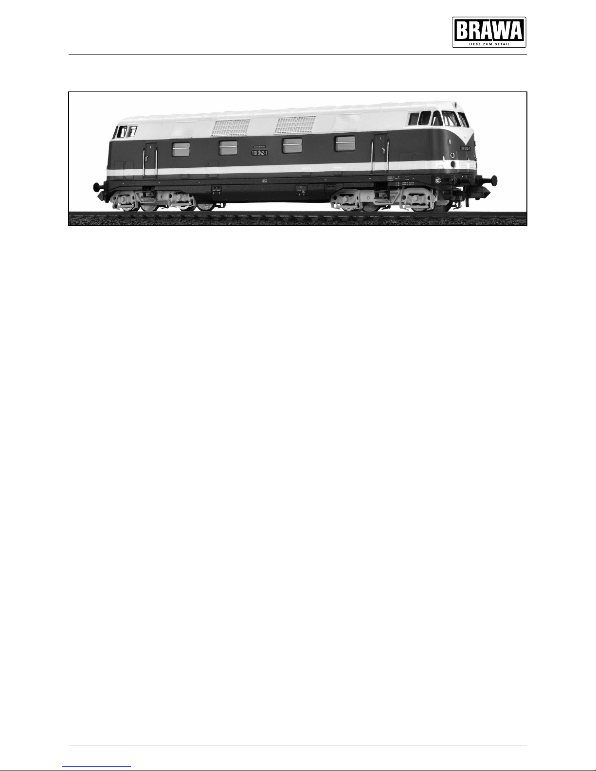
Bis 1970 beschaffte die Deutsche Reichsbahn
206 Exemplare der sechsachsigen BR 180. Ihre
Bauform basiert auf einer Entwicklung vom VEB
Lokomotivbau „Karl Marx“ in Babelsberg. Dort
wurde eine leistungsfähige Streckendiesellokomotive mit B’B’Drehgestellen und hydrodynamischer Leistungsübertragung gebaut. Mit fast
20 Tonnen Achslast eigneten sich diese Loks
nur für den Einsatz auf Hauptbahnen. Für den
Dienst auf Nebenbahnen mit geringer zulässiger
Achslast lieferte Babelsberg seit 1966 Maschinen
der gle ichen Konz eption mit zwe i C’ C’
Drehgestellen. Sie waren ab Werk mit 2 x 735
kW(1000 PS)Antriebsanlagen ausgerüstet,
bewährten sich aber in der Erprobung auch mit
einem Antrieb von jeweils 900 kW (1200 PS). Mit
dieser Leistung war die jetzt als BR 118 bezeichnete Lokomotive in Leistungsbereiche vorgedrungen,
die bisher der Dampftraktion vorbehalten blieben.
Diesellokomotive/Diesel locomotive BR V 180
Until 1970, the East German State Railways
obtained 206 specimen of the sixaxle BR 180.
Its structural shape is based on a design by VEB
Lokomotivbau ‚Karl Marx‘ in Babelsberg. There,
a powerful mainline diesel locomotive with
B’B’bogies and hydrodynamic power transfer
was being built. With almost 20 tons of weight on
the axle, these locomotives were only suitable for
the use on mainline railways. For the service on
secondary railways with a small permissible axle
load, Babelsberg since 1966 supplied engines of
the same design with two C’C’bogies. They were
equipped ex works with 2 x 735 kW (1000 hp) drive
systems, however, during trials they also proved
themselves with a drive of 900 kW (1200 hp) each.
With this performance, the locomotive engine
which was now called BR 118 had penetrated into
performance ranges which had previously been
reserved for steam traction.
Page 2

2
Benennung Seite
• Allgemeine Montage-
und Sicherheitshinweise ...............................3
• Wartungsarbeiten
1. Gehäuse demontieren ...............................4
2. Motor tauschen ........................................4
3. Platine tauschen, LED wechseln ...............4
4. Drehgestell ausbauen, Haftreifen erneuern
Kupplungsschacht tauschen .....................4
5. Ölen .........................................................6
6. Umrüsten auf Digitalbetrieb ......................6
• Ersatzteilliste .........................................7 – 8
• Bestellbeispiel ..............................................9
Inhaltsverzeichnis
Contents
Description Page
• General assembly and safety information .....3
• Maintenance works
1. Dismantling the body ................................4
2. Exchanging the motor ...............................4
3. Exchanging the pcboard, change LED......4
4. Dismantling the bogie, renewing the
adhesion tyres, exchanging the coupling
shaft ........................................................4
5. Lubrication ...............................................6
6. Converting to digital operation ..................6
• Spare parts list ......................................7 – 8
• Order example..............................................9
Page 3
3
Allgemeine Montage und Sicherheits hinweise
General assembly and safety information
• Diese Bedienungsanleitung beschreibt sämtliche Arbeitsvorgänge die zur Wartung
und Instandhaltung notwendig sind. Bitte lesen
Sie diese Bedienungsanleitung bevor Sie mit
den Arbeiten beginnen.
• Bei unsachgemäßem Umgang mit elektrischen
Bauteilen können diese zerstört werden. Für
entsprechende Arbeiten (z.B. Platinenwechsel)
können Sie sich an Ihren Fachhändler oder
den Hersteller wenden.
• Bei den folgenden Wartungsarbeiten ist die
jeweilige Demontage beschrieben, der
Zusammenbau ist in umgekehrter Reihenfolge auszuführen.
• Achten Sie beim Zerlegen der Lokomotive auf
die Einbaulage der entsprechenden Bauteile.
Wird ein Bauteil falsch eingebaut kann dieses
zertört werden oder es kommt zu Funktionsstörungen im Betrieb.
• Jegliche Kabel oder Verbindungsdrähte die
in diesem Produkt verbaut sind dürfen nicht
in eine Netzsteckdose eingeführt werden.
Lebensgefahr!
• These operating instructions describe all work
steps necessary for maintenance and repair.
Please read these operating instructions
carefully before you start with your work.
• In the case of incorrect handling of electrical
components, they may be destroyed. Please
ask your specialist dealer to help with the
necessary work (e.g. changing circuit boards).
• In the case of maintenance work, the
disassembly is described below, to reassemble the tractor reverse the work steps.
• When dismantling the engine make a note of
the mounted position of the individual parts.
An incorrectly mounted part can be destroyed
or operation can be disrupted.
• All cables and connection wires installed in
this product may not be inserted in a mains
socket. Danger!
Maßstabs und originalgetreue Kleinmodelle für erwachsene Sammler.
Zum Betrieb des vorliegenden Produkts
darf als Spannungsquelle nur ein
nach VDE 0551/EN 60742 gefertigter
SpielzeugTransformator verwendet
werden.
Elektro und Elektronikaltgeräte dürfen
nicht in den Hausmüll gelangen. Sie
müssen entsprechend der jeweils
gültigen Länderrichtlinien fachgerecht
entsorgt werden.
Scale and true to original smallsized model for
adult collectors.
Only a toy transformer produced compliant with
VDE 0551/EN 60742 may be used as a voltage
source to operate this product.
Electrical equipment may not reach to domestic
waste. According to the current terms of the
country reference the electrical eqipment must
professional disposed.
Page 4

4
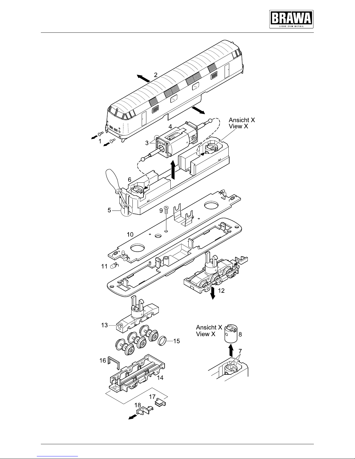
1. Gehäuse demontieren (Fig. 1)
Gehäuse (2) leicht spreizen und nach oben
abnehmen.
2. Motor tauschen (Fig. 1)
Gehäuse demontieren, siehe Punkt 1.
Snapin (3) beider Motorhalterungen nach innen
drücken, Motor (4) mit anhängender Kardanwelle nach oben herausziehen.
3. Platine tauschen, LED wechseln (Fig. 1)
Motor ausbauen, siehe Punkt 2.
Snapin (5) des Gewichtes mit kleinem Schraubenzieher lösen, Gewicht (6) abnehmen.
Snapin (7) beider Drehgestellhalterungen nach
innen drücken und Drehgestellhalterung (8) nach
oben abnehmen.
Achtung:
Nach Abnehmen der Drehgestellhalterung
fällt das Drehgestell nach unten heraus.
Befestigungsschraube (9) der Platine herausdrehen und Platine (10) abnehmen.
Jetzt kann die LED (11) an der Unterseite der
Platine abgelötet werden.
4. Drehgestell ausbauen, Haftreifen erneuern,
Kupplungsschacht tauschen (Fig. 1)
Drehgestell ausbauen
Gehäuse demontieren, siehe Punkt 1.
Snapin (7) der entsprechenden Drehgestellhalterungen nach innen drücken und Drehgestellhalterung (8) nach oben abnehmen. Das
Drehgestell (12) lässt sich jetzt nach unten
herausziehen.
Haftreifen erneuern
Snapin (13) lösen und Drehgestell umdrehen,
Räder müssen nach oben zeigen. Rahmen (14)
abnehmen, jetzt sind die Räder frei zugänglich
und die Haftreifen (15) können erneuert werden.
Kupplungsschacht tauschen
Haltebügel (16) ausclipsen, Kupplungsschacht
(17) mit Kupplung (18) entnehmen.
Kupplung aus Kupplungsschacht ausclipsen.
1. Dismantling the body (Fig. 1)
Spread the body (2) slightly apart and lift off.
2. Exchanging the motor (Fig. 1)
Dismantle the body (see point 1). Press in the
snapin catches (3) of the two motor holders. Lift
out the motor (4) with attached cardan shaft.
3. Exchanging the pcboard,
change LED (Fig. 1)
Dismantle the motor (see point 2).
Release the snapin catch (5) with a small
screwdriver. Remove the weight (6). Press in the
snapin catches (7) of both bogie holders and lift
out the bogie holder (8).
WARNING:
The bogie will fall out at the bottom when the
bogie holder is lifted out.
Unscrew the fastening screw (9) of the
pcboard (10).
The LED (11) underneath the pcboard can now
be unsoldered.
4. Dismantling the bogie Renewing the
adhesion tyres Exchanging the coupling
shaft (Fig. 1)
Dismantling the bogie
Dismantle the body (see point 1). Press in the
snapin catches (7) of the corresponding bogie
holders and liftout the bogie holder (8). The
bogie (12) can be easily pulled out downwards.
Renewing the adhesion tyres
Release the snapin catch (13) and turn over
the bogie; the wheels must be facing upwards.
Remove the frame (14). The wheels are now
freely accessible so that the adhesion tyres (15)
can be renewed.
Exchanging the coupling shaft
Unclip the retaining strap (18). Remove the
coupling shaft (17) with coupling (18). Unclip the
coupling from the coupling shaft.
Wartungsarbeiten
Maintenance works
Page 5
5
Fig. 1
Wartungsarbeiten
Maintenance works
Page 6
6
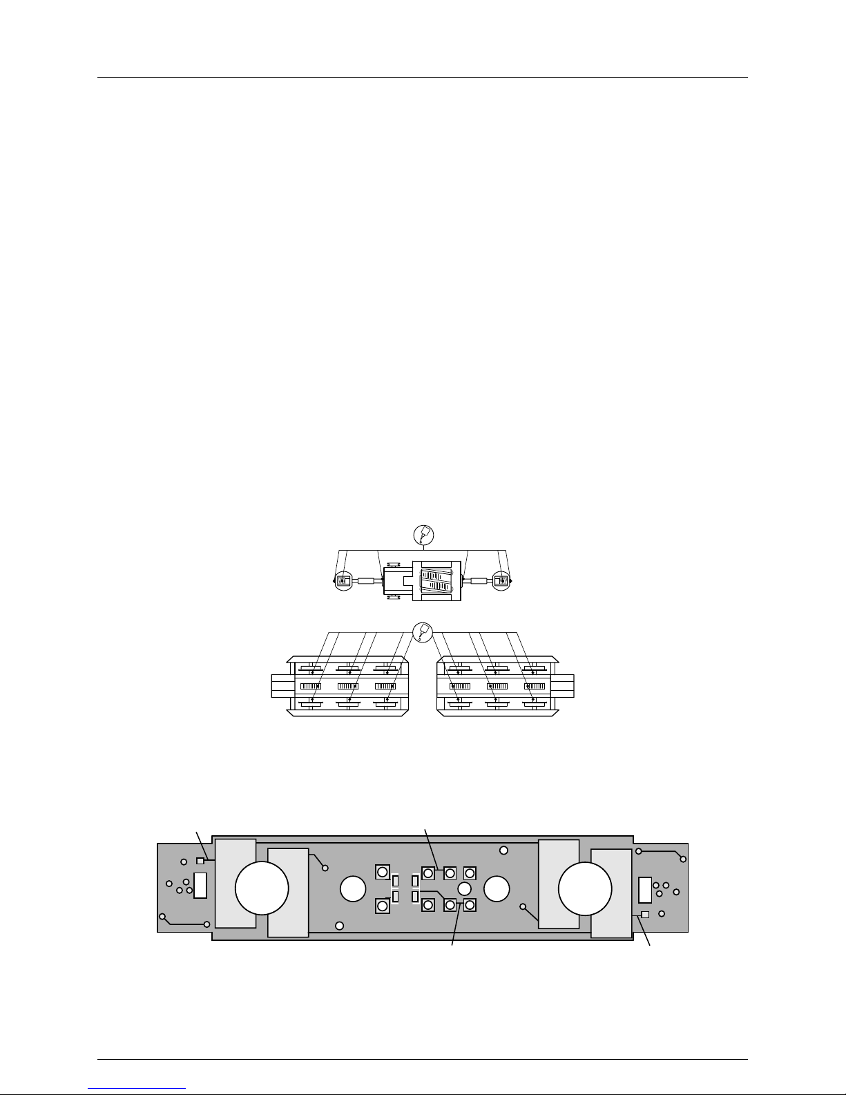
5. Ölen (Fig. 2)
Der Motor und die Lagerstellen der Radsätze
können an den gekennzeichneten Punkten
sparsam mit Öl der Modellbaubranche geölt
werden. Zum Ölen des Motors ist das Gehäuse
abzunehmen, siehe Seite 6 Punkt 1.
6. Umrüsten auf Digitalbetrieb (Fig. 1/3)
Die Lok wird für analogen Gleichstrombetrieb
geliefert.
Gehäuse abnehmen, siehe Punkt 1. Für Digitalbetrieb müssen die Leiterbahnen an den mit X
gekennzeichneten Stellen mit einem Skalpell
oder scharfen Messer sauber durchtrennt
werden, da sonst Kurzschlussgefahr besteht. Die
Kabelenden des Digitaldecoders entsprechend
der Norm NEM 651 bzw. der Nummerierung des
Decoders/Platine anlöten. Digitaldecoder nach
entfernen des Gewichtes (Pos. 6, Fig. 1) im
Rahmen (22) verstauen.
Fig. 2
Motor/Motor
Räder/Wheels
Wartungsarbeiten
Maintenance works
Fig. 3
Platine Unterseite/PCB lower side
X
5. Lubricating (Fig. 2)
The motor and the wheelset bearings may be
sparingly lubricated at the marked places with
oil used for model making purposes. In order
to lubricate the motor, remove the housing,
compare page 8, item 1.
6. Converting to digital operation (Fig. 1/3)
The Eloc is equipped for analogue
directcurrent traction.
Remove body (see (1)). For digital operation, the
strip conductors at the points marked with an
X have to be cleanly separated with a scalpel
or sharp knife, as there is otherwise a risk of
short circuiting. Solder the cable ends of the
digital decoder according to the Norm NEM 651
respectively the numbering of the decoder/pcb.
Pack away the digital decoder in the frame (22)
after removing the weight (Pos. 6, Fig. 1).
X
X X
Page 7
7
Gleichstrom / D.C.current
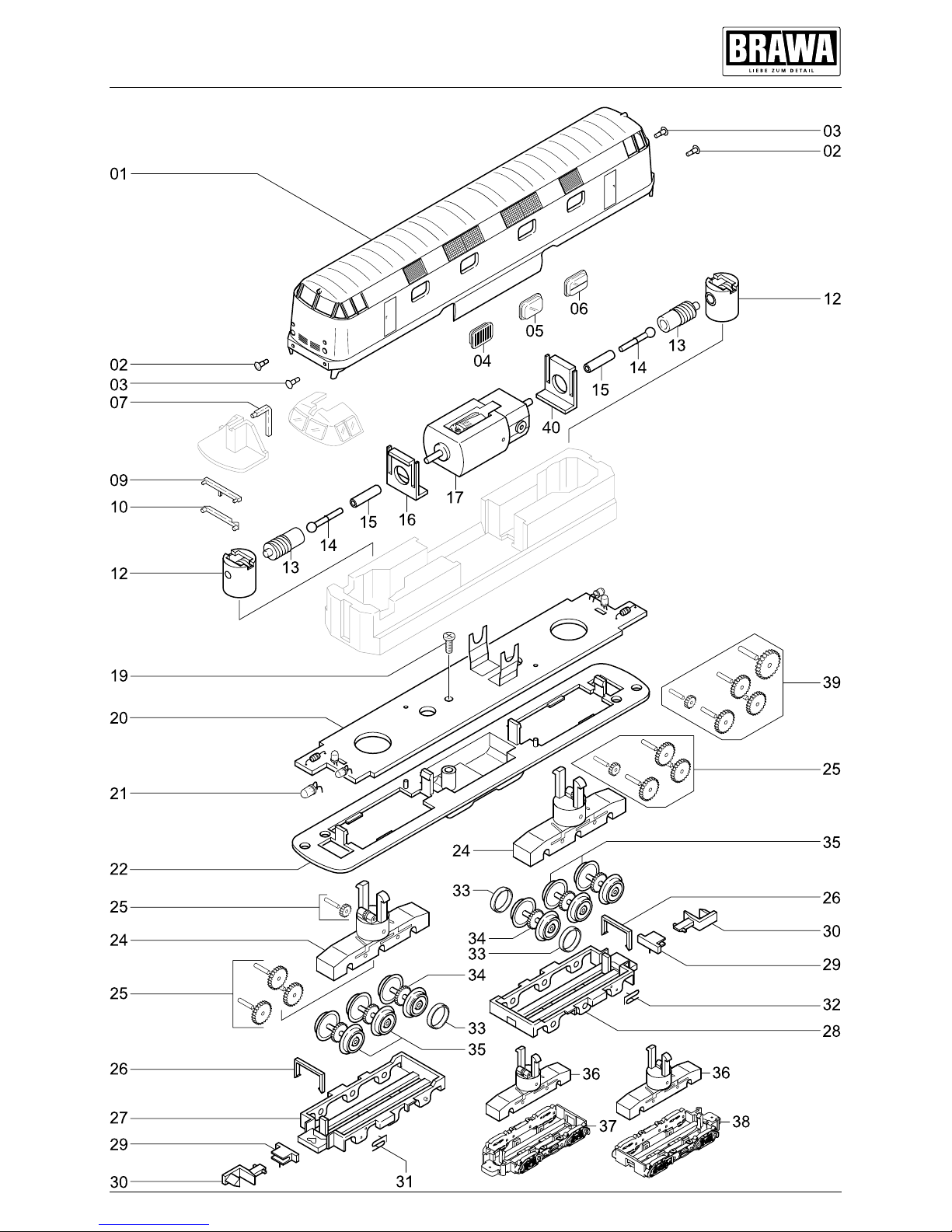
Ersatzteilliste Lokomotive BR V 180
Spare Parts List Locomotive BR V 180
Page 8
8
Ersatzteilliste Lokomotive BR V 180
Spare Parts List Locomotive BR V 180
Artikelnummer/
Article number
Pos. Bennenung Description
Bestell Nr.
Order no.
61186/
118 5487
61186/
118 5529
61187
01 Gehäuse kpl. Body cpl. 0008792.03 – – •
0008822.02 • – –
0008822.03 – • –
02 Puffer gewölbt Buffer round 0008793.00 • • •
Puffer flach Buffer plain 0008794.00 • • •
06 Fenster geteilt Window split 0008815.00 • • –
07 Lichtleiter oben Light bar top 0008797.00 • • •
09 Lichtleiter rot Light bar red 0008799.00 • • •
10 Lichtleiter Light bar 0008800.00 • • •
12 Drehgestellhalter kpl. Bogie holder cpl. 0008742.00 • • •
13 Schnecke mit Pin Worm gear with pin 0008741.00 • • •
14 Kardanwelle Cardan shaft 0008623.00 • • •
15 Silikonschlauch Supple 0008802.00 • • •
16 Motorhalterung dick Motor support thick 0010857.00 • • •
17 Motor Motor 0005028.00 • • •
19 Schraube Screw 0008748.00 • • •
20 Platine kpl. PCB cpl. 0010804.00 • • –
0010805.00 – – •
21 LED LED 0008749.00 • • •
22 Rahmen mit Batteriekasten Frame with battery box 0008807.00 • • •
24 Getriebegehäuse kpl. Gearbox cpl. 0008783.01 – – •
25 Zahnradsatz kpl. Gear wheel set cpl. 0008767.00 – – •
26 Haltebügel Support 0008808.00 • • •
27 Getriebeabdeckung mit Gear box cover with frame 1 0008817.00 – – •
Rahmen 1
28 Getriebeabdeckung mit Gear box cover with frame 2 0008818.00 – – •
Rahmen 2
29 Kupplungsaufnahme NEM 355 Coupler holder NEM 355 0008811.00 • • •
30 Steckkupplung Coupler hook 0004677.00 • • •
31 Kühlschlauch 1 Couling hose 1 0008812.00 – – •
32 Kühlschlauch 2 Couling hose 2 0008813.00 – – •
33 Haftreifen Traction tire 0008417.00 • • •
34 Radsatz mit Haftreifennut Wheelset preparet for traction 0008766.00 • • •
tires
35 Radsatz ohne Haftreifen Wheelset without traction tires 0008765.00 • • •
36 Getriebegehäuse kpl. Gearbox cpl. 0008823.01 • • –
37 Getriebeabdeckung 2 Achsen Gear box cover with frame 1 0008825.01 • • –
mit Rahmen 1
38 Getriebeabdeckung 2 Achsen Gear box cover with frame 2 0008826.01 • • –
mit Rahmen 2
39 Zahnradsatz kpl. Gear wheel set cpl. 0008827.00 • • –
40 Motorhalterung dünn Motor support thin 0010858.00 • • •
• = verfügbar / available
– = nicht verfügbar / not available
Page 9

9
Important notice!
When ordering spare parts you must always
state the order number and give the description. If you do not do this, the order cannot be
processed.
Order example:
Position (17), Motor = 0005028.00, Motor
Wichtiger Hinweis!
Bei der Bestellung von Ersatzteilen muss die
BestellNr. und die
Be nennung angegeben werden. Ist dies nicht
der Fall, kann die Bestellung nicht bearbeitet
werden.
Bestellbeispiel:
Position (17), Motor = 0005028.00, Motor
Page 10

61186.99.50 / 09 12 BRA
Brawa Artur Braun Modellspielwarenfabrik GmbH & Co.
Uferstraße 2628 · D73630 Remshalden
Hotline +49 (0)7151 979 35 68
Telefax +49 (0)7151 746 62
www.brawa.de
 Loading...