

Page 1
Betriebsanleitung
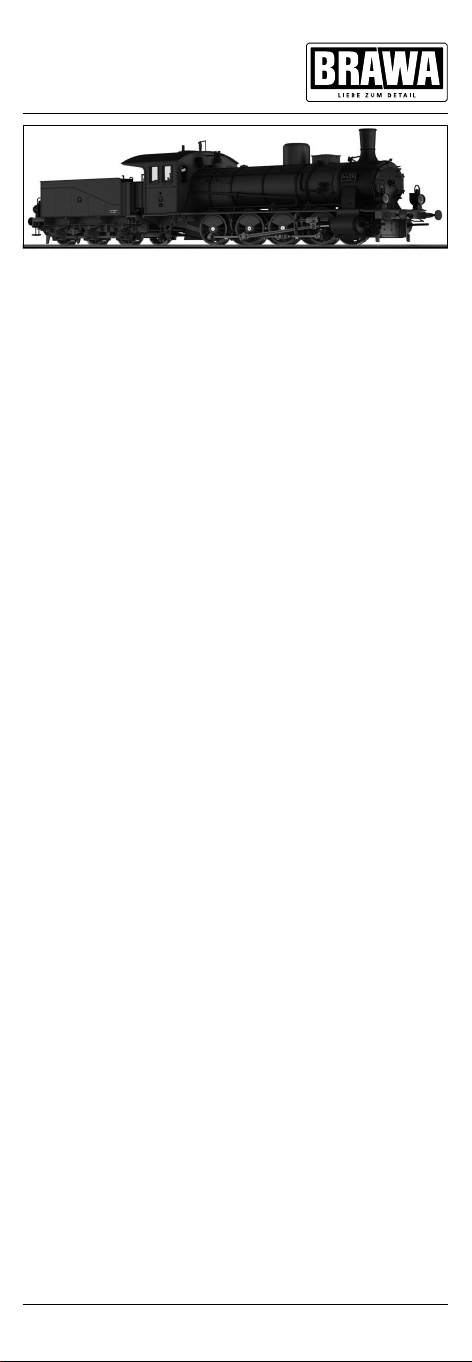
Dampflokomotive BR G7.1
Anfang der 90er-Jahre des vorletzten Jahrhunderts gelangten die 3-fach
gekuppelten Güterzuglokomotiven an ihre Leistungsgrenzen, sodass man
zu 4-fach gekuppelten Radsätzen übergehen musste. Der Betrieb forderte
insbesondere eine Lok, um auf starken und langen Steigungen auf zusätzliche Vorspann- und Schiebedienste verzichten zu können. Sekundär war
die Geschwindigkeit, sodass man glaubte mit einem Raddurchmesser von
1.250 mm auskommen zu können.
Die Konstruktionszeichnungen wurden bei Vulcan in Stettin ausgearbeitet und 1893 die ersten 4 Maschinen abgeliefert. Die Lokomotiven
bewährten sich und wurden unter der Musterblattbezeichnung III 3 d in
die Normalien für Betriebsmittel aufgenommen. Bis 1910 erfolgte an die
Direktionen der K.P.E.V. die Lieferung von über 1.000 G 7.1. Den größten
Anteil beschaffte die KED Essen mit 347 Stück, danach folgten die KED
Cöln mit 197 Maschinen und Breslau mit 84 Lokomotiven. Daran erkennt
man auch, dass das Haupteinsatzgebiet der schwere Güterverkehr in
den Industrierevieren an Rhein und Ruhr sowie in Schlesien war. Neben
der K.P.E.V. hatte im Deutschen Reich auch die LBE (3) und die Gutehoffnungshütte (7) Triebfahrzeuge nach dem Muster der K.P.E.V. beschafft.
Von 1916 bis 1918 ließen die K.P.E.V. nochmals 200 Maschinen bauen.
Auffälligste Änderungen waren die jetzt vorhandenen 2 Sandkästen
und der größere Tender 3T16,5. Diese Lokomotiven wurden nach ihrer
Ablieferung der Königlichen Militäreisenbahn zur Verfügung gestellt und
kamen im Ersten Weltkrieg zum Einsatz. Nach dessen Ende waren in den
Beständen der G 7.1 große Lücken zu beklagen. Viele Lokomotiven gingen
in den Kriegswirren verloren und blieben auf fremden Territorien stehen.
Operating Instructions
Steam locomotive BR G7.1
At the beginning of the 1890s, 3-fold coupled goods train locomotives had
reached the limits of their performance, and it was necessary to pass over
to 4 coupled wheel sets. The operation particularly called for a locomotive
in order to do without additional harnessing and pushing services on
intense and long slopes. Speed was secondary, and a wheel diameter
of 1,250 mm was thought to be sufficient. The design drawings were
prepared by Vulcan in Stettin, and the first 4 machines were delivered in
1893. The locomotives proved their worth, and they were included under
the master drawing designation III 3 d in the standards for uniform design
and construction („Normalien“) for operating equipment. Until 1910, more
than 1,000 G 71 locomotives were delivered to the directorates of the
Royal Prussian Railway Administration (K.P.E.V.). The KED Essen bought
the majority with 347 units, KED Cöln came in second with 197 machines,
and Breslau bought 84 locomotives. As this shows, the main application of
heavy goods traffic was in the industrial belt on the Rhine and the Ruhr, as
well as in Silesia. In addition to the K.P.E.V., LBE (3) and Gutehoffnungshütte
(7) had also purchased tractive units in the Deutsches Reich according to
the pattern of the K.P.E.V. From 1916 to 1918, the K.P.E.V. had about 200
more machines built. The most striking changes were the 2 sandboxes
that were now available, and the larger tender 3T16,5. These locomotives
were available to the royal military railway after their delivery, and came
into use in the First World War. Once the war ended, there were large
gaps in the G71 stocks. Many locomotives were lost in the chaos of war,
remaining in foreign territories.
1
Page 2

Inhaltsverzeichnis
Contents
Benennung Seite
Allgemeine Montage und Sicherheitshinweise .................................... 2
Arbeiten vor der Inbetriebnahme
• Entnahme der Lok aus der Verpackung ............................................ 4
• Zusatzbauteile montieren ................................................................ 4
• Bügelkupplung montieren................................................................ 5
Wartungsarbeiten
• 1. Ölen ........................................................................................... 5
• 2. Gehäuse demontieren ................................................................6
• 3. Tendergehäuse demontieren ...................................................... 6
• 4. Platine tauschen ........................................................................ 6
• 5. Motor tauschen .......................................................................... 6
• 6. Digitaldecoder tauschen ............................................................. 6
• 7. Haftreifen tauschen .................................................................... 6
• 8. Schleiferwechsel bei Wechselstromausführung .......................... 6
• 9. Wartungsarbeiten an Radsätzen und Getriebe ............................6
• 10. Umrüsten auf Digitalbetrieb ....................................................... 8
Funktionstastenbelegung für Soundmodelle ......................................... 9
Ersatzteilliste ............................................................................. 14 – 26
Bestellhinweis
• Bestellbeispiel ...............................................................................27
Allgemeine Montage und Sicherheitshinweise
• Diese Bedienungsanleitung beschreibt sämtliche Arbeitsvorgänge die
zur Wartung und Instandhaltung notwendig sind. Bitte lesen Sie diese
Bedienungsanleitung bevor Sie mit den Arbeiten beginnen.
• Bei unsachgemäßem Umgang mit elektrischen Bauteilen können
diese zerstört werden. Für entsprechende Arbeiten (z.B. Platinenwechsel) können Sie sich an Ihren Fachhändler oder den Hersteller
wenden.
• Bei den folgenden Wartungsarbeiten ist die jeweilige Demontage
beschrieben, der Zusammenbau ist in umgekehrter Reihenfolge
auszuführen.
• Die folgenden Wartungsarbeiten sind bei Gleich und
WechselstromAusführungen fast identisch. Im Ausnahmefall wird im
entsprechenden Textabschnitt Bezug genommen.
• Jegliche Kabel oder Verbindungsdrähte die in diesem Produkt verbaut
sind dürfen nicht in eine Netzsteckdose eingeführt werden. Lebensgefahr!
• Dieses Modell ist auf märklinMetallgleisen nur bedingt einsatzfähig.
märklin ist eingetragenes Warenzeichen der „Geb. Märklin & Cie. GmbH Göppingen“
2
Page 3

Description Page
General assembly and safty information............................................... 3
Work to be performed before starting up
• Removing the locomotive from the packaging ................................. 4
• Fitting additional parts ..................................................................... 4
• Fitting bow coupling ........................................................................ 5
Maintenance work
• 1. Lubricating ................................................................................. 5
• 2. Dismantling the locomotive casing ............................................. 7
• 3. Dismantling the tender casing .................................................... 7
• 4. Exchanging the motherboard ......................................................7
• 5. Exchanging the motor ................................................................7
• 6. Exchanging the digital decoder ...................................................7
• 7. Replace the traction wheels .......................................................7
• 8. Exchanging the pick-up in the AC version ...................................7
• 9. Maintenance work on the wheel sets and gears ......................... 7
• 10. Converting to digital operation .................................................... 8
Function keys for sound models ...........................................................9
Spare parts list ..........................................................................14 – 26
Order notice
• Order example............................................................................... 27
General assembly and safety information
• These operating instructions describe all work steps necessary for
maintenance and repair. Please read these operating instructions
carefully before you start with your work.
• In the case of incorrect handling of electrical components, they may
be destroyed. Please ask your specialist dealer to help with the
necessary work (e.g. changing circuit boards).
• In the case of maintenance work, the disassembly is described below,
to reassemble the tractor reverse the work steps.
• The maintenance work described below is virtually identical
for direct current and alternating current models. If there are
any differences these will be pointed out specifically.
• All cables and connection wires installed in this product may not be
inserted in a mains socket. Danger!
• This model fits conditionally to märklin metals.
märklin is a registered trademark of the „Geb. Märklin & Cie. GmbH Göppingen“
3
Page 4
Arbeiten vor der Inbetriebnahme
Work to be performed before starting up
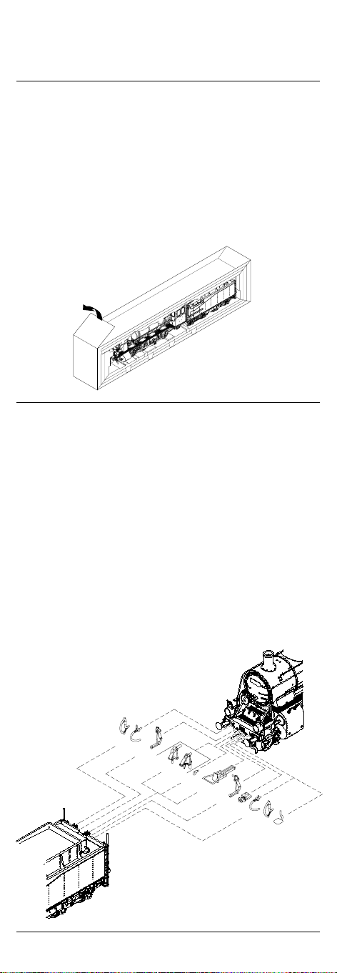
Entnahme der Lok aus der Verpackung (Fig. 1)
Deckel der Verpackung öffnen. KunststoffSchutzverpackung
mit Lok entnehmen und auf einen Tisch oder ähnliches abstellen.
Lasche (1) lösen, Deckel und Seitenteile der Schutzverpackung wegklappen, Lok entnehmen.
Removing the locomotive from packaging (Fig. 1)
Open package lid. Take out plastics protecting package with
engine and put it down on a table or similar item.
Loosen latch (1), fold away lid and side parts of protecting package,
take out engine and take out engine.
Fig. 1
1
Zusatzbauteile montieren (Fig. 2)
In der Verpackung sind zusätzliche Bauteile lose beigelegt. Siehe Seite
15, Pos. 240 und 241. Anzahl der Bauteile abhängig von Epoche.
• 5 = 2x Bügelkupplung (Montage siehe Seite 5)
Werden die Bauteile aus dem Zurüstbeutel für Vitrinenmodelle montiert,
ist die Lok nicht mehr für den Fahrbetrieb geeignet.
• 1 = Bremsschlauch
• 2 = Heizschlauch
• 3 = Zughaken
• 4 = Haken
• 6 = Ventil
• 7 = Stirntritt
Fitting additional parts (Fig. 2)
Accessory parts have been loosely enclosed in the packaging. See page
15, position 240 and 241. Amount of parts depends on era.
• 5 = 2x Bow coupling (Fitting see page 5)
If the components from the addon bag for display models are mounted, then the engine will no longer be suitable for operation.
• 1 = Brake hose
• 2 = Heating hose
• 3 = Original coupling
• 4 = Hook
• 6 = Valve
• 7 = Step front
Fig. 2
1
2
3
4
5
2
6
1
7
4
Page 5

Wartungsarbeiten
Maintenance works
Bügelkupplung montieren (Fig. 5)
Bremsgestänge (77) abnehmen. Schrauben (66) herausdrehen und
Aschekasten (72) und Bodenplatte (107) abnehmen. Geschlossene
Kinematikabdeckung (108) herausziehen. Feder (44) ausclipsen und
Kinematik (42) herausnehmen. Kinematikverlängerung (43) in Kinematik (42) einclipsen. Bügelkupplung (233) in Kinematikverlängerung (43)
einclipsen.
Fitting bow coupling (Fig. 5)
Demount the brake linkage (77). Remove the screws (66) and remove
the ash box (72) and base plate (107). Remove the closed kinematic
cover (108). Unclip the spring (44) and remove kinematics (42). Clip
the kinematics extension (43) in kinematics (42). Clip the bow coupling
(233) in kinematic extension (43).
1. Ölen (Fig. 4)
Der Motor und die Lagerstellen der Radsätze können an den gekennzeichneten Punkten sparsam mit Öl der Modellbaubranche geölt
werden. Zum Ölen des Motors ist das Gehäuse abzunehmen, siehe
Seite 6, Punkt 2.
1. Lubricating (Fig. 4)
The engine and the wheelset bearings may be sparingly lubricated at
the marked places with oil used for model making purposes.
In order to lubricate the engine, remove the housing, compare page 10,
item 2.
Fig. 4
Motor
Engine
Räder
Wheels
5
Page 6

Wartungsarbeiten
Maintenance Work
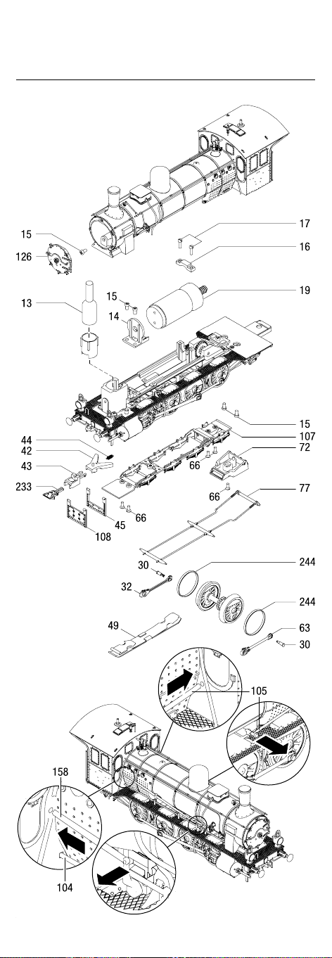
2. Gehäuse demontieren (Fig. 5)
Rauchkammertür (126) abnehmen und Schraube (15) herausdrehen.
Schrauben (15) an der Fahrgestellunterseite und herausdrehen und das
Lokomotivengehäuse vorsichtig nach oben abnehmen.
Achtung! (Fig. 5a)
Die Steuerstange (158) und die Hebel für Entwässerung (104, 105)
sind mit dem Fahrgestell verbunden und am Umsteuerungshebel
bzw. Führerhaus eingesteckt. Bei der Demontage des Lokomotivengehäuses muss die Steuerstange (158) und der Hebel (105) aus dem
Umsteuerungshebel herausgezogen werden. Beim Zusammenbau der
Lokomotive darauf achten, das die Steuerstange (158) und die Hebel
(104, 105) an den entsprechenden Bohrungen am Umsteuerungshebel
bzw. am Führerhaus montiert werden.
3. Tendergehäuse demontieren (Fig. 6)
Werkzeugkasten (185) entfernen. Schrauben (186) an der Gehäuseunterseite herausdrehen, Tendergehäuse (108) vorsichtig nach oben
abnehmen.
4. Platine tauschen (Fig. 6)
Tendergehäuse demontieren, siehe Punkt 3. Brückenstecker (170)
bei Gleichstrom-Ausführung DC oder Digitaldecoder (169) bei
Wechselstrom-Ausführung AC abziehen. Befestigungsschrauben (213)
herausdrehen. Sämtliche Kabel durch Abziehen der Kabelhalter (171)
entfernen. Bitte kennzeichnen Sie sich wo die einzelnen Kabel befestigt
waren. Platine (172) nach oben abnehmen.
5. Motor tauschen (Fig. 5)
Lokomotivengehäuse demontieren, siehe Punkt 2. Schrauben (15, 17)
der Motorhalter (14, 16) herausdrehen. Motorhalter entfernen, Motor (19)
vorsichtig anheben und Kabel am Motor ablöten.
6. Digitaldecoder tauschen (Fig. 6)
Tendergehäuse demontieren, siehe Punkt 3 . Digitaldecoder (169) abziehen
und neuen Decoder einstecken.
7. Haftreifen tauschen (Fig. 5)
Kurbelzapfen (30) ausclipsen. Kuppelstange (32 bzw. 63) zur Seite schieben
und Haftreifen (244) wechseln.
8. Schleifer tauschen bei Wechselstromausführung
(Fig. 5)
Schleifer (49) aus Halterung an Bodenplatte (243) ausclipsen.
9. Wartungsarbeiten an Radsätzen und Getriebe
(Fig. 5)
Bei Wartungsarbeiten an den Radsätzen, dem Kuppelgestänge und dem
Getriebe muss das gesamte Fahrgestell zerlegt werden. Wir bitten Sie
bei der Demontage des Fahrgestells genau darauf zu achten, wo und
wie jedes Einzelteil montiert war. Die Einbau lage können Sie auch aus
der Ersatzteilgrafik Seite 13 bis 16 ersehen. Für Beschädigungen, die
durch unsachgemäße Arbeiten an den Bauteilen entstehen, kann die
Firma BRAWA nicht haftbar gemacht werden.
6
Page 7

2. Dismantling the locomotive casing (Fig. 5)
Demount the smoke chamber door (126) and unscrew the screw (15).
Undo the screws (81) on the underside of the running gear and carefully
remove the locomotive housing from above.
Important! (Fig. 5a)
The reversing rod (158) and the lever drainage (104, 105) are connected to the running gear and are inserted into the reversing lever and
driver‘s cab respectively. When dismantling the locomotive housing the
reversing rod (158) and the lever (105) must be pulled out of the reversing lever. When assembling the locomotive, ensure that the reversing
rod (158) and the lever (104, 105) are mounted in the corresponding
holes in the reversing lever and driver‘s cab respectively.
3. Dismantling the tender casing (Fig. 6)
Remove toolbox (185). Unscrew the screws (186) on the underneath of
the tender casing and lift the tender casing (108) up carefully.
4. Exchanging the motherboard (Fig. 6)
Remove the tender casing, see point 3. Remove blind socket (170) for
direct current model DC or digital decoder (169) for alternating current
version. Unscrew attachment screws (213). Remove all cables by
pulling off the cabel lug (171). Please mark where the individual cables
were fixed. Lift out motherboard (172).
5. Exchanging the motor (Fig. 5)
Remove locomotive casing, see point 2. Unscrew the screws (15, 17) of
the motor holder (14, 16). Remove motor holders, lift motor (19) carefully and unsolder the cable to the motor.
6. Exchanging the digital decoder (Fig. 6)
Remove the tender casing, see point 3. Pull out digital decoder (169)
and insert new unit.
7. Exchanging traction wheels (Fig. 5)
Unclip the crankpin (30). Push the coupling rod (32 or 63) to the side
and replace the traction tyres (244).
8. Exchanging the pickup in the AC version (Fig. 5)
Unclip the pick-up shoe support (49) from the holder at the base plate
(243).
9. Maintenance work on the wheel sets and gears
(Fig. 5)
When performing maintenance work on the wheel sets, the coupling
rods and the gears, the whole chassis must be dismantled. We would
remind you to note exactly where and how each part was assembled
before dismantling the chassis. The installation position can be seen in
the spare parts chart on pages 13 to 16. BRAWA is not liable for damage which occurs due to improper work on construction parts.
7
Page 8

Wartungsarbeiten
Maintenance Work
10. Umrüsten auf Digitalbetrieb
GleichstromAusführung
Tendergehäuse (108) abnehmen, Brückenstecker (170) abziehen und
Digital-Decoder (169) einstecken.
Den richtigen Einbau des Digitaldecoders und dessen Einsteck
richtung entnehmen Sie der Einbauvorschrift des Decoderherstel
lers.
WechselstromAusführung
Lokomotiven in Wechselstrom-Ausführung AC werden serienmäßig mit
Premium-Digitaldecoder (169) ausge liefert. Der Decoder erkennt die
Betriebsart (analog/digital) selbstständig. Soll der Decoder umprogramiert werden, liegt die Einbau- und Betriebsanleitung PremiumDigitaldecoder bei.
Der Decoder ist werkseitig auf Adresse 03 eingestellt.
10. Converting to digital operation
DC version
Remove tender housing (108), pull off dummy connector (170) and
insert digital decoder (169).
Please consult the installation instructions issued by the decoder
manufacturer for correct installation of the digital decoder and its
insert direction.
AC version
The premium digital decoder (169) is standard for the alternating current (AC) locomotives models. The decoder independently identifies the
operation type (analog/digital). Please refer to the enclosed installation
and operation instructions “Premium Digital Decoder” in the event that
the decoder needs to be reprogrammed.
The decoder is set to address 03 in the factory.
8
Page 9

Funktionstastenbelegung für Soundmodelle/
Function keys for sound models
F0 Licht vorn, Light front,
Lichtmachine Generator
F1 Sound AN/AUS, Sound ON/OFF,
F2 Pfeife Whistle
F3 Injektor Injector
F4 Rauchgenerator (AUX 1) Smoke generator (AUX 1)
F5 Luftpumpe Air pump
F6 Beschleunigungs- Acceleration/deceleration,
/Bremszeit, Rangiergang shunting mode
F7 Kurvenquietschen AN/AUS Curve squeaking ON/OFF
F8 Kohle schaufeln (AUX 3/4) Coal shoveling (AUX 3/4)
F9 Zylinder ausblasen Cylinder blowing
F10 Schaffnerpfiff Conductor whistle
F11 Kupplungsgeräusch Coupling noise
F12 Sanden Sanding
F13 Bremse lösen/anlegen Release/Insert brake
F14 Kabinenlicht (AUX 2) Cabin light (AUX 2)
F15 Kurzpfiff Whistle short
F16 Sicherheitsventil Safety valve
F17 Schienenstöße AN/AUS Rail joints ON/OFF
F18 Aschenkasten rütteln Ash box shaking
F19 Wasserpumpe Water pump
F20 Lichtmaschine AN/AUS Generator ON/OFF
Achtung!
Bitte beachten Sie das unter M4/mfx nur Funktionen von F1 bis F15
abgerufen werden können. Alle anderen Funktionen darüber hinaus
können momentan nur mit einer RailComPlus
®
fähigen Zentrale abge-
rufen werden.
Important!
Please note that under M4/mfx only functions can be accessed from F1
to F15. All other functions can also currently be accessed only with a
RailComPlus® capable center.
RailComPlus® ist eingetragenes Warenzeichen der „Lenz Elektronik GmbH“
RailComPlus® is a registered trademark of the „Lenz Elektronik GmbH“
9
Page 10
Wartungsarbeiten
Maintenance Work
Fig. 5
Fig. 5a
10
Page 11
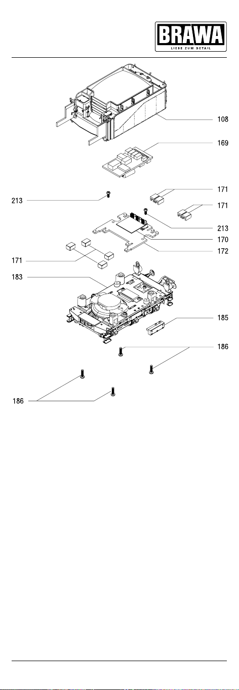
Fig. 6
11
Page 12
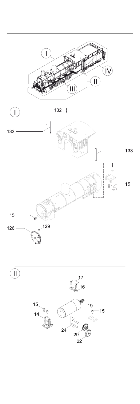
Ersatzteilliste
Spare Parts List
12
Page 13
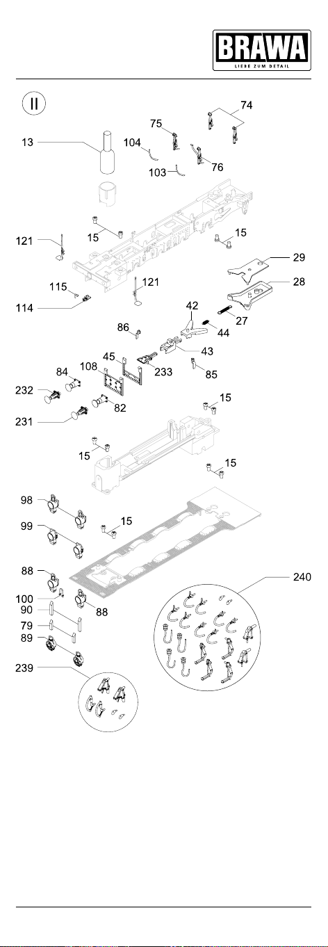
13
Page 14
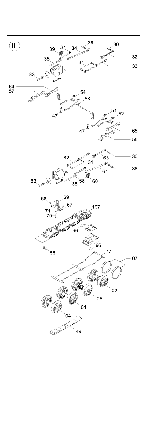
Ersatzteilliste
Spare Parts List
14
Page 15
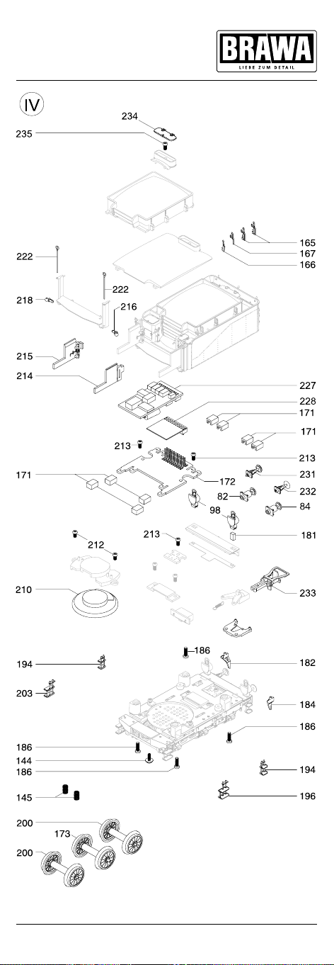
15
Page 16
Ersatzteilliste
Spare Parts List
40737 / 40739 AC
40736 / 40738 DC
40733 / 40735 AC
40732 / 40734 DC
40729 / 40731 AC
40728 / 40730 DC
40725 / 40727 AC
40724 / 40726 DC
40721 / 40723 AC
Artikelnummer/Article number
40720 / 40722 DC
40717 / 40719 AC
40716 / 40718 DC
40713 / 40715 AC
40712 / 40714 DC
40709 / 40711 AC
40708 / 40710 DC
40705 / 40707 AC
40704 / 40706 DC
40701 / 40703 AC
40700 / 40702 DC
0010944.01 – – – – – – – – – – • – – – – – – – – –
Bestell Nr.
Order no.
– – – – – – – – – –
0010954.01 – – • – – – – – • –
0010954.00 • – – – – – – – – – – – – – – – – – – –
0010949.01 – – – – – – – – – – – • – – – – – – – –
0010949.00 – – – – – • – • – – – – – – – – – – – –
0010948.01 – – – – – – – – – – • – – – – – – – – –
0010951.03 – – – – – – – – – – – – – – – – – • – –
0010951.02 – – – – – – – – – – – – – • – • – – – •
0010951.01 – – – • – – – – – • – – – – – – – – – –
0010951.00 – • – – – – – – – – – – – – – – – – – –
0010950.03 – – – – – – – – – – – – – – – – • – – –
0010950.02 – – – – – – – – – – – – • – • – – – • –
0010950.01 – – • – – – – – • – – – – – – – – – – –
0010950.00 • – – – – – – – – – – – – – – – – – – –
0010945.01 – – – – – – – – – – – • – – – – – – – –
0010945.00 – – – – – • – • – – – – – – – – – – – –
0010954.02 – – – – – – – – – – – – • – • – – – • –
Pos. Bennenung Description
2 Kuppelradsatz mit Haftreifennut Wheelset with traction tire 0010944.00 – – – – • – • – – – – – – – – – – – – –
4 Kuppelradsatz Wheelset 0010948.00 – – – – • – • – – – – – – – – – – – – –
16
Page 17

• • • • • • • •
0010953.03 – – – – – – – – – – – – – – – – – • – –
0010953.02 – – – – – – – – – – – – – • – • – – – •
0010953.01 – – – • – – – – – • – – – – – – – – – –
0010953.00 – • – – – – – – – – – – – – – – – – – –
0010952.03 – – – – – – – – – – – – – – – – • – – –
0010952.02 – – – – – – – – – – – – • – • – – – • –
0010952.01 – – • – – – – – • – – – – – – – – – – –
0010952.00 • – – – – – – – – – – – – – – – – – – –
0010947.01 – – – – – – – – – – – • – – – – – – – –
0010947.00 – – – – – • – • – – – – – – – – – – – –
0010946.01 – – – – – – – – – – • – – – – – – – – –
0010955.03 – – – – – – – – – – – – – – – – – • – –
0010955.02 – – – – – – – – – – – – – • – • – – – •
0010955.01 – – – • – – – – – • – – – – – – – – – –
0010955.00 – • – – – – – – – – – – – – – – – – – –
0010954.03 – – – – – – – – – – – – – – – – • – – –
13 Raucheinsatz Smoking box 0005069.00 • • • • • • • • • • • •
6 Treibradsatz Wheelset 0010946.00 – – – – • – • – – – – – – – – – – – – –
7 Haftreifen Traction tires 0007551.00 • • • • • • • • • • • • • • • • • • • •
14 Halterung Motor Motor mount 0007425.00 • • • • • • • • • • • • • • • • • • • •
19 Motor kpl. Motor cpl. 0010960.00 • • • • • • • • • • • • • • • • • • • •
17 Zylinderschraube Cylinder head screw 0007154.00 • • • • • • • • • • • • • • • • • • • •
16 Motorhalter vorn Motor holder 0007624.00 • • • • • • • • • • • • • • • • • • • •
15 Zylinderschraube mit Kreuzschlitz Cap screw 0007628.00 • • • • • • • • • • • • • • • • • • • •
17
Page 18
Ersatzteilliste
Spare Parts List
40737 / 40739 AC
40736 / 40738 DC
40733 / 40735 AC
40732 / 40734 DC
40729 / 40731 AC
40728 / 40730 DC
40725 / 40727 AC
40724 / 40726 DC
40721 / 40723 AC
40720 / 40722 DC
40717 / 40719 AC
40716 / 40718 DC
Artikelnummer/Article number
40713 / 40715 AC
40712 / 40714 DC
40709 / 40711 AC
40708 / 40710 DC
• • • – – – – – – – – – –
40705 / 40707 AC
40704 / 40706 DC
40701 / 40703 AC
40700 / 40702 DC
Bestell Nr.
Order no.
0007430.03 – – – – – – – – – – – – – – – – • • – –
0007430.02 – – • • • • • • – – – – – – – – – – – –
0007430.01 – – – – – – – – • • • • • • • • – – • •
0007429.03 – – – – – – – – – – – – – – – – • • – –
0007429.02 – – • • • • • • – – – – – – – – – – – –
0007429.01 – – – – – – – – • • • • • • • • – – • •
0007433.00 – – – – – – •
0007433.01 – – – – – – – – – – – – – – – – – – • •
22 Zahnrad Gear 0007443.00 • • • • • • • • • • • • • • • • • • • •
Pos. Bennenung Description
20 Zahnrad Reduction gear 0003424.00 • • • • • • • • • • • • • • • • • • • •
34 Treibstange rechts Blowing right rod 0007922.00 • • • • • • – – – – • • • • • • • • – –
32 Kuppelstange Dome rod 0007431.00 • • • • • • • • • • • • • • • • • • • •
31 Kurbelbolzen Valve gear pin 0003505.00 • • • • • • • • • • • • • • • • • • • •
28 Kinematik Unterteil Kinematics under some 0007429.00 • • – – – – – – – – – – – – – – – – – –
27 Feder Kinematik hinten Spring 0007625.00 • • • • • • • • • • • • • • • • • • • •
24 Zylinderstift Cylinder pin 0007631.00 • • • • • • • • • • • • • • • • • • • •
29 Kinematik Oberteil Kinematics 0007430.00 • • – – – – – – – – – – – – – – – – – –
30 Kurbelzapfen-1 Crankpin 1 0006938.00 • • • • • • • • • • • • • • • • • • • •
33 Kuppelstange vorn Dome rod forwars 0007432.00 • • • • • • • • • • • • • • • • • • • •
18
Page 19
0007442.03 – – – – – – – – – – – – – – – – • • – –
0007442.02 – – • • • • • • – – – – – – – – – – – –
0007442.01 – – – – – – – – • • • • • • • • – – • •
Hebel Steuerung Fahrwerk links Lever controll left 0007447.00 • • • • • • • • • • • • • • • • • • • •
56
54 Vorwertsexcenter rechts Stored value eccentric right 0007484.00 • • • • • • • • • • • • • • • • • • • •
53 Rückwertsexcenter rechts Return value eccentric right 0007483.00 • • • • • • • • • • • • • • • • • • • •
52 Vorwertsexcenter links Stored value eccentric left 0007449.00 • • • • • • • • • • • • • • • • • • • •
51 Rückwertsexcenter links Return value eccentric left 0007448.00 • • • • • • • • • • • • • • • • • • • •
49 Schleifer kpl. Pick-up cpl. 0008901.00 – • – • – • – • – • – • – • – • – • – •
45 Kinemaikabdeckung NEM Kinematics cover 0007442.00 • • – – – – – – – – – – – – – – – – – –
44 Zugfeder-Kinematik Spring coupler socket 0003589.00 • • • • • • • • • • • • • • • • • • • •
43 NEM Schacht NEM shaft 0007441.00 • • • • • • • • • • • • • • • • • • • •
42 Kinematik vorn Forward kinematics 0007440.00 • • • • • • • • • • • • • • • • • • • •
39 Kreuzkopf rechts Crosshead right 0007438.00 • • • • • • • • • • • • • • • • • • • •
38 Gegenkurbel Against crank 0007437.00 • • • • • • • • • • • • • • • • • • • •
37 Gleitbahn rechts Slipway right 0007436.00 • • • • • • • • • • • • • • • • • • • •
35 Kolbenstange Piston rod 0007434.00 • • • • • • • • • • • • • • • • • • • •
47 Schwingenkulisse Swinging backdrop 0007444.00 • • • • • • • • • • • • • • • • • • • •
58 Gleitbahn links Slipway left 0007450.00 • • • • • • • • • • • • • • • • • • • •
57 Hebel Steuerung Fahrwerk rechts Lever control right 0007456.00 • • • • • • • • • • • • • • • • • • • •
0007921.00 • • • • • • – – – – • • • • • • • • – –
0007453.01 – – – – – – – – – – – – – – – – – – • •
63 Kuppelstange links Dome rod left 0007455.00 • • • • • • • • • • • • • • • • • • • •
62 Kuppelstange A B C links Coupling rod ABC left 0007454.00 • • • • • • • • • • • • • • • • • • • •
61 Treibstange links Blowing rod left 0007453.00 – – – – – – • • • • – – – – – – – – – –
60 Kreuzkopf links Crosshead left 0007451.00 • • • • • • • • • • • • • • • • • • • •
19
Page 20
Ersatzteilliste
Spare Parts List
40737 / 40739 AC
40736 / 40738 DC
40733 / 40735 AC
40732 / 40734 DC
40729 / 40731 AC
40728 / 40730 DC
40725 / 40727 AC
40724 / 40726 DC
40721 / 40723 AC
40720 / 40722 DC
40717 / 40719 AC
40716 / 40718 DC
Artikelnummer/Article number
40713 / 40715 AC
40712 / 40714 DC
40709 / 40711 AC
40708 / 40710 DC
40705 / 40707 AC
40704 / 40706 DC
40701 / 40703 AC
40700 / 40702 DC
Bestell Nr.
Order no.
– – – – – – • • – – • • – – • • • •
0007494.01 – –
0007493.01 – – – – – – – – • • – – • • – – • • • •
0007558.01 – – – – – – – – • • • • – – • • – – • •
0007464.02 – – – – – – – – – – • • • • • • – – • •
0007464.01 – – • • • • • • – – – – – – – – – – – –
0007557.01 – – – – – – – – • • • • – – • • – – • •
65 Wippe hinten links Bouncing back left 0007458.00 • • • • • • • • • • • • • • • • • • • •
Pos. Bennenung Description
64 Wippe hinten Bouncing back 0007457.00 • • • • • • • • • • • • • • • • • • • •
Bremse mit Sandfallrohr rechts Brake with sand falling pipe right 0007493.00 • • – – – – – – – – – – – – – – – – – –
75 Bremse mit Sandfallrohr C rechts Brake with sand falling pipe C right 0007558.00 – – • • • • • • – – – – – – – – – – – –
74 Bremse Brake 0007464.00 • • – – – – – – – – – – – – – – – – – –
71 Kontak Schleifer Contact rail pickup 0007462.00 – • – • – • – • – • – • – • – • – • – •
70 Senkschraube Countersunk 0007627.00 • • • • • • • • • • • • • • • • • • • •
69 Abdeckung Radschleifer Caover rail pickup 0007461.00 • • • • • • • • • • • • • • • • • • • •
68 Radschleifer AB links Rail pickup AB left 0007460.00 • • • • • • • • • • • • • • • • • • • •
67 Radschleifer AB rechts Rail pickup AB right 0007459.00 • • • • • • • • • • • • • • • • • • • •
66 Senkschraube Countersunk 0007626.00 • • • • • • • • • • • • • • • • • • • •
Bremse mit Sandfallrohr C links Brake with sand falling pipe C left 0007557.00 – – • • • • • • – – – – – – – – – – – –
76 Brems mit Sandfallrohr links Brake with sand falling pipe left 0007494.00 • • – – – – – – – – – – – – – – – – – –
20
Page 21
– – • • • • – –
0007475.02 – – – – – – – – • • • • • • • • • • • •
0007475.01 – – • • • • • • – – – – – – – – – – – –
0007474.02 – – – – – – – – • • • • • • • • • • • •
0007474.01 – – • • • • • • – – – – – – – – – – – –
0010939.01 – – – – – – – – • • • • • • • • – – • •
0010940.01 – – – – – – – – • • • • • • • • – – • •
0007466.02 – – – – – – – – • • • • • • • • • • • •
0007466.01 – – • • • • • • – – – – – – – – – – – –
0007562.01 – – – – – – – – • • • • – – • • – – • •
82 Hülsenpuffer flach kpl. Buffer flad cpl. 0010940.00 – – • • • • • • – – – – – – – – – – – –
79 Lichtleiter kurz Fiber optics short 0007597.00 – – – – • • • • – – – – • • – – – – • •
77 Bremsgestänge Brake linkage 0007466.00 • • – – – – – – – – – – – – – – – – – –
103 Sandfallrohr C links Sand falling pipe C left 0007562.00 – – • • • • • • – – – – – – – – – – – –
100 Stirn Griff Frontal attack 0007491.00 • • • • – – • • – – – – • • • • – – • •
99 Einheitslampe kpl. Lamp new style 0010942.00 – – – – • • • • – – – – – – – – – – – –
98 Petroleumlampe kpl. Lamp old style 0010941.00 • • • • – – – – • • • • – – – – • • • •
90 Lichtleiter Fiber optics 0007479.00 • • • • – – – – • • • •
89 Lampe It. kpl. Lamp It. cpl. 0010943.00 – – – – – – – – – – – – – – • • – – – –
88 Lampe SNCF kpl. Lamp SNCF cpl. 0010943.01 – – – – – – – – – – – – • • – – – – – –
86 Schienenräumer rechts Obstructions remover right 0007475.00 • • – – – – – – – – – – – – – – – – – –
85 Schienenräumer links Obstructions removers left 0007474.00 • • – – – – – – – – – – – – – – – – – –
84 Hülsenpuffer gewölbt kpl. Buffer round cpl. 0010939.00 – – • • • • • • – – – – – – – – – – – –
83 Kolbenstangenschutzrohr Pistion rod protection tube 0007472.00 • • • • • • • • • • • • • • • • • • • •
21
Page 22
Ersatzteilliste
Spare Parts List
40737 / 40739 AC
40736 / 40738 DC
Artikelnummer/Article number
40733 / 40735 AC
40732 / 40734 DC
40729 / 40731 AC
40728 / 40730 DC
40725 / 40727 AC
40724 / 40726 DC
40721 / 40723 AC
40720 / 40722 DC
40717 / 40719 AC
40716 / 40718 DC
40713 / 40715 AC
40712 / 40714 DC
40709 / 40711 AC
40708 / 40710 DC
40705 / 40707 AC
40704 / 40706 DC
40701 / 40703 AC
40700 / 40702 DC
– – –
Bestell Nr.
Order no.
Pos. Bennenung Description
0007556.01 – – – – • – • – • – – – – – – – – – – –
0007563.01 – – – – – – – – • • • • – – • • – – • •
Bodenplatte 3 Leiter Bottom plate by three leaders 0007504.00 – • – – – – – – – – – – – – – – – – – –
107 Bodenplatte Bottom plate 0007556.00 • – • – – – – – – – – – – – – – – – – –
104 Sandfallrohr C rechts Sandfallinf pipe C right 0007563.00 – – • • • • • • – – – – – – – – – – – –
108 Kinematikabdeckung Kinematics cover 0007561.00 • • – – – – – – – – – – – – – – – – – –
114 Absperrgriff Control lever 0007044.00 – – – – • • • • • • • • • • • • • • • •
0007606.01 – – • • – – • • – – – – – – – – – – – –
115 Heizkupplungsaufnahme vorn Front pipe connector 0003509.02 – – – – – – – – • • • • – – • • –
115 Heizkupplungsaufnahme vorn Front pipe connector 0003509.01 – – – – • • • • – – – – – – – – – – – –
121 Stirntritt Front occurs 0007606.00 • • – – – – – – – – – – – – – – – – – –
0007561.03 – – – – – – – – – – – – – – – – • • – –
0007561.02 – – – – – – – – • • • • • • • • – – • •
0007561.01 – – • • • • • • – – – – – – – – – – – –
0007504.03 – – – – – – – – – – – – – – – – – • – –
0007504.02 – – – – – – – – – • – • – • – • – – – •
0007504.01 – – – • – • – • – – – – – – – – – – – –
0007556.03 – – – – – – – – – – – – – – – – • – – –
0007556.02 – – – – – – – – – – • – • – • – – – • –
22
Page 23
• • • • • – –
0010958.01 – – – – – – • • – – – – – – – – – – – –
0010958.00 – – – – • • – – – – – – – – – – – – – –
0010957.00 – – – – – – – – – – – – – – – – – – • •
0007606.02 – – – – – – – – – – – – • • • • – – • •
Halter 3 gerade Holder 3 0007659.00 • • • • – – • • • • • • • • • • • • • •
167 Halter 2 zum Stecken Holder 2 0007658.00 • • • • • • – – – – – – •
166 Halter 4 schräg Holder 4 0007660.00 • • • • – – • • • • • • • • • • • • • •
165 Halter 1 zum einhängen Holder 1 0007657.00 • • • • • • – – – – – – • • • • • • – –
145 Feder Spring 0007638.00 • • • • • • • • • • • • • • • • • • • •
144 Schraube Screw 0007632.00 • • • • • • • • • • • • • • • • • • • •
133 Griffstange Führerhaus Handle rod cab 0007510.00 • • • • • • • • • • • • • • • • • • • •
132 Pfeife Whistle 0003580.00 • • • • • • • • • • • • • • • • • • • •
126 Rauchkammertür kpl. Smoke box door cpl. 0010956.00 • • – – – – – – – – – – • • – – – – – –
129 Lampenhalter Kessel Lamp holder boiler 0007509.00 • • • • • • • • • • • • • • • • • • • •
0010933.01 – – • – • – • – • – – – – – – – – – – –
173 Radsatz Tender mittig Center wheelset tender 0010933.00 • – – – – – – – – – – – – – – – – – – –
172 Hauptplatine PCB 0007716.00 • • • • • • • • • • • • • • • • • • • •
171 Kabelhalter Holder for wire 0003998.00 • • • • • • • • • • • • • • • • • • • •
0010961.00 – – • • – – – – – – – – – – – – – – – –
0010959.00 – – – – – – – – – – – – – – • • • • – –
0010958.03 – – – – – – – – – – • • – – – – – – – –
0010958.02 – – – – – – – – • • – – – – – – – – – –
0010934.01 – – – • – • – • – • – – – – – – – – – –
0010934.00 – • – – – – – – – – – – – – – – – – – –
0010933.03 – – – – – – – – – – – – – – – – • – – –
0010933.02 – – – – – – – – – – • – • – • – – – • –
23
Page 24
Ersatzteilliste
Spare Parts List
40737 / 40739 AC
40736 / 40738 DC
40733 / 40735 AC
40732 / 40734 DC
40729 / 40731 AC
40728 / 40730 DC
Artikelnummer/Article number
40725 / 40727 AC
40724 / 40726 DC
40721 / 40723 AC
40720 / 40722 DC
40717 / 40719 AC
40716 / 40718 DC
40713 / 40715 AC
40712 / 40714 DC
40709 / 40711 AC
40708 / 40710 DC
40705 / 40707 AC
40704 / 40706 DC
40701 / 40703 AC
40700 / 40702 DC
0010934.03 – – – – – – – – – – – – – – – – – • – –
Bestell Nr.
Order no.
– – – – – – –
0007664.02 – – – – – – – – • • • • • • • • • • • •
0007664.01 – – • • • • • • – – – – – – – – – – – –
0007665.02 – – – – – – – – • • • • • • • • • • • •
0007665.01 – – • • • • • • – – – – – – – – – – – –
0007662.02 – – – – – – – – • • • • • • • • • • • •
0007662.01 – – • • • • • • – – – – – – – – – – – –
0007661.02 – – – – – – – – • • • • • • • • • • • •
0007661.01 – – • • • • • • – – – – – – – – – – – –
0010935.02 – – – – – – – – – – • – • – • – – – • –
0010935.01 – – • – • – • – • – – – – – – – – – – –
Pos. Bennenung Description
173 Radsatz Tender mittig Center wheelset tender 0010934.02 – – – – – – – – – – – • – • – • – – – •
200 Radsatz Tender Wheelset 0010935.00 • – – – – – – – – – – – –
196 Aufstieg Tender links Tender step left 0007664.00 • • – – – – – – – – – – – – – – – – – –
194 Treppe Tender hinten Step tender rear side 0007665.00 • • – – – – – – – – – – – – – – – – – –
186 Schraube Screw 0010930.00 • • • • • • • • • • • • • • • • • • • •
184 Schienenräumer hinten links Track cleaner rear left 0007662.00 • • – – – – – – – – – – – – – – – – – –
182 Schienenräumer hinten rechts Track cleaner rear right 0007661.00 • • – – – – – – – – – – – – – – – – – –
181 Lichtleiter hinten Light bar rear 0007694.00 • • • • • • • • • • • • • • • • • • • •
24
Page 25
• • • • •
0010932.01 – – • • • • • • • • • • • • • • • • • •
0007663.02 – – – – – – – – • • • • • • • • • • • •
0007663.01 – – • • • • • • – – – – – – – – – – – –
0010936.03 – – – – – – – – – – – – – – – – – • – –
0010936.02 – – – – – – – – – – – • – • – • – – – •
0010936.01 – – – • – • – • – • – – – – – – – – – –
0010936.00 – • – – – – – – – – – – – – – – – – – –
0010935.03 – – – – – – – – – – – – – – – – • – – –
210 Lautsprecher 23 mm rund 4 Ohm Speaker 23 mm round 4 Ohm 0005068.00 • • • • • • • • • • • • • • • • • • • •
203 Aufstieg Tender rechts Tender step right 0007663.00 • • – – – – – – – – – – – – – – – – – –
0010931.01 – – • • • • • • • • • • • • • • • • • •
222 Griffstange Handrail 0007687.00 • • • • • • • • • • • • • • •
218 Halter für Griffstange rechts Handle support right 0007688.00 • • • • • • • • • • • • • • • • • • • •
216 Halter für Griffstange links Handrail support left 0007689.00 • • • • • • • • • • • • • • • • • • • •
215 Türe rechts kpl. Door right cpl. 0010932.00 • • – – – – – – – – – – – – – – – – – –
214 Türe links kpl. Door left cpl. 0010931.00 • • – – – – – – – – – – – – – – – – – –
213 Schraube Screw 0007720.00 • • • • • • • • • • • • • • • • • • • •
212 Schraube Screw 0010929.00 • • • • • • • • • • • • • • • • • • • •
227 Universaldecoder 21-pol. V4 Universaldecoder 21-pol. V4 0005049.00 • • • • • • • • • • • • • • • • • • • •
0010938.01 – – – – – – – – – – – – – – – – • • – –
Sounddecoder 21-pol. V4 Sounddecoder 21-pol. V4 0005051.00 • • • • • • • • • • • • • • • • • • • •
231 Stangenpuffer flach kpl. Buffer flad cpl. 0010938.00 • • – – – – – – – – – – – – – – – – – –
228 Brückenstecker Blind plug 0010963.00 • – • – • – • – • – • – • – • – • – • –
25
Page 26
Artikelnummer/Article number
40737 / 40739 AC
40736 / 40738 DC
40733 / 40735 AC
40732 / 40734 DC
40729 / 40731 AC
40728 / 40730 DC
40725 / 40727 AC
40724 / 40726 DC
40721 / 40723 AC
40720 / 40722 DC
40717 / 40719 AC
40716 / 40718 DC
40713 / 40715 AC
40712 / 40714 DC
40709 / 40711 AC
40708 / 40710 DC
40705 / 40707 AC
40704 / 40706 DC
40701 / 40703 AC
40700 / 40702 DC
0010937.01 – – – – – – – – – – – – – – – – • • – –
Bestell Nr.
Order no.
Pos. Bennenung Description
232 Stangenpuffer gewölbt kpl. Buffer round cpl. 0010937.00 • • – – – – – – – – – – – – – – – – – –
Part not available
/
Part available
/
• Bauteil erhältlich
– Bauteil nicht erhältlich
240 Zurüsbeutel Epoche II-VI Add-on bag Era II-VI 0000751.00 – – • • • • • • • • • • • • • • • • • •
239 Zurüsbeutel Epoche I Add-on bag Era I 0000749.00 • • – – – – – – – – – – – – – – – – – –
235 Schraube Screw 0007720.00 – • • • • • • • • • • • • • • • • • • •
234 Deckel Cover 0007655.00 – • • • • • • • • • • • • • • • • • • •
233 Bügelkupplung Coupler 0000729.00 • • • • • • • • • • • • • • • • • • • •
26
Page 27

Bestellhinweis
Bei der Bestellung von Ersatzteilen muss die Ersatzteil BestellNr. und die Benennung angegeben werden. Ist dies nicht der Fall, kann die Bestellung nicht
bearbeitet werden.
Bestellbeispiel:
Position (19), Motor kpl. = 0010960.00, Motor kpl.
Order notice
When ordering spare parts you must always state the order number and give the
description. If you do not do this, the order cannot be processed.
Order example:
Position (19), Motor cpl. = 0010960.00, Motor cpl.
27
Page 28
Maßstabs und originalgetreue Kleinmodelle für erwachsene
Sammler.
Scale and true to original smallsized model for adult collectors.
Zum Betrieb des vorliegenden Produkts darf als Spannungsquelle nur ein nach VDE 0551/EN 60742 gefertigter
SpielzeugTransformator verwendet werden.
Only a toy transformer produced compliant with VDE 0551/
EN 60742 may be used as a voltage source to operate this
product.
Dieses Produkt entspricht den gültigen CE Normen.
This product conforms to the current CE standards.
Elektro und Elektronikaltgeräte dürfen nicht in den Hausmüll
gelangen. Sie müssen entsprechend der jeweils gültigen
Länderrichtlinien fachgerecht entsorgt werden.
Electrical equipment may not reach to domestic waste.
According to the current terms of the country reference the
electrical eqipment must professional disposed.
Brawa Artur Braun Modellspielwarenfabrik GmbH & Co
Uferstraße 2628 · D73630 Remshalden
Hotline +49 (0) 7151 979 35 68
Telefax +49 (0) 7151 746 62
www.brawa.de
.
40700.50.250 / 12 12 – BRA
 Loading...