

Page 1

Betriebsanleitung
Dampflokomotive mit
Schlepptender BR 06 001 – H0
Ausführung Gleichstrom 0636
Ausführung Wechselstrom 0637
Die Deutsche Reichsbahn Gesellschaft schrieb 1934 den Bau einer
vierfach gekuppelten Schnellzuglok aus. Den Auftrag für den Bau von
zunächst zwei Lokomotiven der Baureihe 06 erhielt die Firma Krupp
in Essen. Der Bau der Dampflok BR 06 001 dauerte von 1934 bis
1939. Diese lange Bauzeit lässt sich nur damit erklären, dass schon
bald nach der Auftragserteilung das Interesse der DR an dieser
„Riesenlokomotive“ schwand. Als die Dampflok 06 001 im März 1939
ausgeliefert wurde, war bereits die Realisierung der Baureihe 01.10
als neue Generation schwerer Schnellzugloks beschlossen worden.
Die Baureihe 06 hatte Treibräder von 2000 mm Durchmesser und je
ein vorderes und hinteres Drehgestell. Das Dreizylinder-Triebwerk
sollte Laufruhe bis zu einer Höchstgeschwindigkeit von 140 km/h
ermöglichen. Gekuppelt mit dem 5-achsigen Tender T38St hatte die
BR 06 eine LüP von 26520 mm und war so die größte deutsche
Schnellzuglok. Die Reibungslast betrug 80 t, die Dienstlast der Lok
141 t, das Gesamtgewicht von Lok und Tender 224 t. Sehr zufrieden
war man mit dem Fahrwerk der Baureihe 06, mehrere zeitgenössische Berichte heben ausdrücklich den ruhigen Lauf der Maschine
auch bei hohen Geschwindigkeiten hervor. Die hohe Zugkraft weckte
ebenfalls Begeisterung. Weniger zufriedenstellend war dagegen der
Betrieb mit dem Kessel, der mit 7,50 m Rohrlänge zum Problemkind
geworden war. Das von der Reichsbahn verfochtene Prinzip des Langrohrkessels mit kleiner Feuerbüchsheizfläche war in eine Sackgasse
geraten. Bis 1952 standen die Loks in Frankfurt und Hanau, dann
wurden sie in Darmstadt und Braunschweig verschrottet.
1
Page 2

Locomotive with trailing tender BR 06 001 – H0
Locomotive à vapeur à tender séparé BR 06 001 – H0
Operating Instructions
Direct current model 0636
Alternating current model 0637
In 1934, the Deutsche Reichsbahn Gesellschaft gave out an invitation
to tender for the construction of an express train with four
couplings.The initial construction order was for two locomotives from
the 06 series and was awarded to Krupp in Essen. The construction
of the steam locomotive BR 06 001 took from 1934 to 1939. This
long construction time can only be explained by the fact that shortly
after the order was given, DR’s interest in the “giant locomotive” faded.
When the locomotive was finally delivered in March 1939, the decision
to realise the 01.10 series, a new generation of heavy express train
locomotives, had been made. The 06 series had driving wheels with
a diameter of 2000 mm and both a front and rear bogie. The threecylinder valve gear and connecting rods was supposed to enable easy
running up to a top speed of 140 km/h. When coupled to the 5-axle
tender T38St, the BR 06 had an total length of 26 520 mm which
made it the largest German express train. The frictional load was 80t,
the locomotive’s service weight was 141t, the total weight of the
locomotive and tender was 224t. They were very pleased with the
chassis of the 06 series, several reports of the time expressly
complimented on the smooth running of the machine even at high
speed. The high level of pulling power was also cause for enthusiasm!
Less satisfactory however, was the tank which had become a problem
with its 7.5 m long pipe. The principle which the Reichsbahn favoured,
the long piped tank with small firebox heating surfaces, had come to
a dead end. Until 1952 the locomotives stood in Frankfurt and Hanau
and then they were scrapped in Darmstadt and Braunschweig.
Instructions de service
Modèle à courant continu 0636
Modèle à courant alternativ 0637
En 1934, la „Deutsche Reichsbahn“ (compagnie des chemins de fer
du Reich allemand) fit un appel d’offres pour la construction d’une
locomotive de train rapide à attelage quadruple. La société Krupp
d’Essen reçut, pour commencer, la commande de deux locomotives
de la série 06. La construction de la locomotive à vapeur BR 06 001
dura de 1934 à 1939. Cette longue durée de construction ne peut
s’expliquer que par le fait que pour la DR cette „locomotive
gigantesque“ perdit de son intérêt. Lorsqu’en mars 1939, la locomotive
à vapeur 06 001 fut livrée, la réalisation de la série 01.10 en tant que
nouvelle génération des locomotives lourdes des trains rapides, était
déjà décidée. La série 06 avait des roues motrices de 2000 mm de
diamètre et respectivement un bogie avant et arrière. Le mécanisme
moteur à trois cylindres devait permettre une marche silencieuse
jusqu’à une vitesse maximale de 140 km/h. Attelée au tender à 5
essieux T38St, avec une longueur hors tampons de 26 520 mm, la
BR 06 était la plus grande locomotive allemande. La charge de friction
était de 80 t, la charge de service de la locomotive de 141 t, le poids
total de la locomotive et du tender de 224 t. On était très satisfait du
mécanisme de roulement de la série 06, plusieurs rapports de l’époque
soulignent expressément la marche silencieuse de la machine, même
à grandes vitesses. La grande capacité de traction était aussi source
d’enthousiasme. Mais par contre, le service de la chaudière était moins
2
Page 3

Locomotiva a vapore con
tender BR 06 001 – H0
satisfaisant puisque avec une longueur de tuyauterie de 7.50 m, il
était devenu le problème n°1. Le principe de la chaudière à longue
tuyauterie et des petites surfaces de chauffe des boîtes à feu, soutenu
par la Reichbahn, était dans une impasse. Jusqu’en 1952, les
locomotives se trouvaient à Francfort et à Hanau, puis elles furent
mises à la ferraille à Darmstadt et à Brunswick.
Istruzioni sul funzionamento
Modello a corrente continua 0636
Modello a corrente alternata 0637
Nel 1934, la società delle Ferrovie Statali Tedesche bandì un concorso
per la costruzione di una locomotiva per treni rapidi con
accoppiamento quadruplo. La ditta Krupp di Essen ricevette la
commessa per la costruzione di, inizialmente, due locomotive della
serie 06. La realizzazione della locomotiva a vapore BR 06 001 durò
dal 1934 al 1939. Il lungo tempo richiesto per la costruzione può
essere spiegato solo dal fatto che, immediatamente dopo il
conferimento dell’ordine, l’interesse del Reich tedesco per questa
“Locomotiva gigante” svanì. Quando, nel marzo 1939, la locomotiva
a vapore 06 001 venne consegnata, era già stata decisa la realizzazione
della serie 01.10, come nuova generazione di grandi locomotive per
treni rapidi. La serie 06 aveva ruote motrici di 2000 mm di diametro
e un carrello anteriore e posteriore. Il meccanismo a tre cilindri doveva
garantire una silenziosità di funzionamento fino ad una velocità
massima di 140 km/h. Accoppiata con il tender a 5 assi T38St, la
BR 06 aveva una lunghezza, respingenti compresi, di 26520 mm ed
era quindi la locomotiva per treni rapidi più grande della Germania. Il
carico d’attrito era di 80 t, quello d’esercizio della locomotiva di 141 t,
il peso globale di locomotiva e tender di 224 t. Il carrello della serie
06 riscosse molto consenso, molte cronache dell’epoca evidenziavano
espressamente la silenziosità della corsa della macchina anche ad
alte velocità. Anche la grande forza di trazione scatenò molto
entusiasmo. Meno soddisfacente fu invece il funzionamento con la
caldaia che, con una lunghezza dei tubi di 7.50 m, creava problemi. Il
principio della caldaia con tubi lunghi e con una piccola superficie di
riscaldamento del focolaio, difeso dalle Ferrovie Statali, era finito in
un vicolo cieco. Fino al 1952 le locomotive si trovavano a Francoforte
e Hanau, in seguito furono rottamate a Darmstadt e Braunschweig.
3
Page 4

Inhaltsverzeichnis
Contents
Benennung Seite
Allgemeine Montage- und Sicherheitshinweise ............................. 5
Entnahme der Lok aus der Verpackung ......................................... 6
Wichtige Arbeiten vor der Inbetriebnahme .................................... 6
Zusatzbauteile montieren............................................................... 7
Wartungsarbeiten
• 1. Ölen....................................................................................... 8
• 2. Seuthe Raucheinsatz montieren ............................................ 8
• 3. Umrüsten auf Digitalbetrieb .................................................. 9
• 4. Lokomotivengehäuse demontieren ..................................... 10
• 5. Tendergehäuse demontieren ............................................... 10
• 6. Platine tauschen .................................................................. 10
• 7. Motor tauschen ................................................................... 10
• 8. Digitaldecoder tauschen ...................................................... 10
• 9. Haftreifen tauschen ............................................................. 10
• 10. Schleifer tauschen bei Wechselstromausführung ............. 10
• 11. Glühbirnen tauschen ......................................................... 10
• 12. Wartungsarbeiten an Radsätze und Getriebe..................... 10
Ersatzteilliste
Gleichstrom- und Wechselstrom-Ausführung ..... 14, 15, 16, 17, 18
Bestellbeispiel.............................................................................. 18
Description Page
General assembly and safety information ...................................... 5
Removing the locomotive from the packaging .............................. 6
Imortent work bevore starting ....................................................... 6
Fitting additional parts ................................................................... 7
Maintenance works
• 1. Lubricating ............................................................................ 8
• 2. Mounting the Seuthe smoke insert ....................................... 8
• 3. Conversion to digital operation ............................................. 9
• 4. Dismantling Locomotive housing ........................................ 12
• 5. Dismantling Tender housing................................................ 12
• 6. Exchanging the circuit board ............................................... 12
• 7. Exchanging motor ............................................................... 12
• 8. Exchanging digital decoder ................................................. 12
• 9. Exchanging traction tires..................................................... 12
• 10. Exchanging pick-up on alternating current version ........... 12
• 12. Exchanging bulbs .............................................................. 12
• 12. Maintenance work on wheel sets and gear ........................ 12
Spare parts list
direct current and alternating current .................. 14, 15, 18, 19, 20
Order example ............................................................................. 20
4
Page 5

Allgemeine Montage- und Sicherheitshinweise
• Diese Bedienungsanleitung beschreibt sämtliche Arbeitsvorgänge
die zur Wartung und Instandhaltung notwendig sind.
Bitte lesen Sie diese Bedienungsanleitung bevor Sie mit den
Arbeiten beginnen.
• Bei unsachgemäßem Umgang mit elektrischen Bauteilen können
diese zerstört werden. Für entsprechende Arbeiten
(z.B. Platinenwechsel) können Sie sich an Ihren Fachhändler
oder den Hersteller wenden.
• Bei den folgenden Wartungsarbeiten ist die jeweilige Demontage
beschrieben, der Zusammenbau ist in umgekehrter Reihenfolge
auszuführen.
• Die folgenden Wartungsarbeiten sind bei Gleich- und Wechselstrom-Ausführungen fast identisch. Im Ausnahmefall wird im
entsprechenden Textabschnitt Bezug genommen.
• Empfohlene Betriebsarten in Abhängigkeit vom Schienenradius:
Schienenradius Betrieb
300 mm nicht Zulässig
360 mm max. 50 % der Geschwindigkeit
420 mm empfolener Radius
General assembly and safety information
• These operating instructions describe all work steps necessary
for maintenance and repair. Please read these operating
instructions carefully before you start with your work.
• In the case of incorrect handling of electrical components, they
may be destroyed. Please ask your specialist dealer to help with
the necessary work (e.g. changing circuit boards).
• In the case of maintenance work, the disassembly is described
below, to re-assemble the tractor reverse the work steps.
• Recommend operating modes in dependency of the rail radius:
Rail radius Operation
300 mm not allowed
360 mm max. 50 % speed
420 mm Recommend one radius
5
Page 6

Arbeiten vor der Inbetriebnahme
Work to be performed before starting up
Entnahme der Lok aus der Verpackung (Fig. 1)
Verpackung öffnen. Kunststoff-Schutzverpackung
mit Lok entnehmen und auf einen Tisch oder ähnliches abstellen.
Lasche (1) lösen, Deckel und Seitenteile der Schutzverpackung
wegklappen, Lok entnehmen.
Removing the locomitive from the Packaging (Fig. 1)
Open package. Take out plastics protecting package with
engine and put it down on a table or similar item. Loosen latch (1),
fold away lid and side parts of protecting package, take out engine.
Fig. 1
1
Wichtige Arbeiten vor der Inbetriebnahme (Fig. 2)
Lösen Sie die Schrauben (1) an der Unterseite der Lokomotive, um
die Zylinderabdeckungen (2) und die Blenden (3) abzumontieren,
da diese für den Fahrbetrieb nicht geeignet sind.
Important work before starting (Fig. 2)
Remove the screws (1) from the underside of the locomotive in
order to dismantle the cylinder covers (2) and the panels (3),
because they are not suitable for the driving mode.
Fig. 2
3
1
3
1
2
1
2
1
6
Page 7

Zusatzbauteile montieren (Fig. 3)
In der Verpackung sind zusätzliche Bauteile lose beigelegt.
•1 = 2 x Bügelkupplung
•2 = Faltenbalg klein
•3 = Faltenbalg groß
•4 = 2 x Bügel für Faltenbalg klein
•5 = 2 x Bügel für Faltenbalg groß
•6 = 2 x Heizschlauch
•7 = 4 x Bremsschlauch
•8 = Lichtmaschiene
•9 = 2 x Originalkupplung
• 10 = 2 x Kolbenschutzrohr
Werden die Bauteile Pos 9 und 10 für Vitrinenmodelle
montiert, ist die Lok nicht mehr für den Fahrbetrieb geeignet.
Fitting additional parts (Fig. 3)
Accessory parts have been loosely enclosed in the packaging.
•1 = 2 x Bow coupling
•2 = Diaphragm open style
•3 = Diaphragm close style
•4 = 2 x Support for Diaphragm open style
•5 = 2 x Support for Diaphragm close style
•6 = 2 x Heating hose
•7 = 4 x Brake hose
•8 = Dynamo
•9 = 2 x Original coupling
• 10 = 2 x Piston rod cover pipe
If the components from the add-on bag for display models are
mounted, then the engine will no longer be suitable for operation.
Fig. 3
6
7
5
5
3
1
4
4
9
7
6
2
10
8
10
7
Page 8

Wartungsarbeiten
Maintenance works
1. Ölen (Fig. 4)
Der Motor und die Lagerstellen der Radsätze können an den
gekennzeichneten Punkten sparsam mit Öl der Modellbaubranche
geölt werden. Zum Ölen des Motors ist das Gehäuse abzunehmen,
siehe Seite 10 Punkt 4.
1. Lubricating (Fig. 4)
The engine and the wheelset bearings may be sparingly lubricated
at the marked places with oil used for model making purposes.
In order to lubricate the engine, remove the housing, compare page
12, item 4.
Fig. 4
Motor
Engine
Lokomotive
Locomotive
Tender
Tender
2. Seuthe Raucheinsatz montieren (Fig. 5)
Gehäuse abnehmen, siehe Seite 10 Punkt 4.
Raucheinsatz (1) in Hülse (2) einsetzen und Gehäuse montieren.
2. Mounting the Seuthe smoke insert (Fig. 5)
Remove housing, compare page 12, item 4.
Place the smoke insert (1) in the sleeve (2) and mount the housing.
Fig. 5
1
2
8
Page 9

Umrüsten auf Digitalbetrieb
Gleichstrom Ausführung 0636
Tendergehäuse abnehmen, Blindstecker (04) abziehen und DigitalDecoder (05) einstecken (siehe Seite 11).
Den richtigen Einbau des Digitaldecoders und dessen
Einsteckrichtung entnehmen Sie der Einbauvorschrift
des Decoderherstellers.
Nach Einstecken des Digitaldecoders ist die Funktion des Lichtes zu
prüfen. Wenn keine Lichtfunktion – Stecker um 180° drehen und
einstecken.
Wechselstrom-Ausführung 0637
Lokomotiven in Wechselstrom-Ausführung AC werden serienmäßig
mit Premium-Digitaldecoder (05) ausgeliefert. Der Decoder erkennt
die Betriebsart (analog / digital) selbstständig. Soll der Decoder
umprogramiert werden, liegt die Einbau- und Betriebsanleitung
Premium-Digitaldecoder bei.
Der Decoder ist Werkseitig auf Adresse 03 eingestellt.
Converting to digital operation
DC version 0636
Remove Tenderhousing, pull off dummy connector (04) and insert
digital decoder (13), (see page 13).
Please consult the installation instructions issued by the decoder
manufacturer for correct installation of the digital decoder and
its insert direction.
After inserting the digital decoder, check that the light functions. If
the light does not work, turn the connector through 180°.
AC version 0637
The premium digital decoder (05) is standard for the alternating
current (AC) locomotives models. The decoder independently
identifies the operation type (analogue/digital). Please refer to the
enclosed installation and operation instructions “Premium Digital
Decoder” in the event that the decoder needs to be reprogrammed.
The decoder is set to address 03 in the factory.
9
Page 10

Wartungsarbeiten
4. Lokomotivengehäuse demontieren (Fig. 6)
Schrauben (01) an der Gehäuseunterseite herausdrehen,
Lokomotivengehäuse (02) vorsichtig nach oben abnehmen.
5. Tendergehäuse demontieren (Fig. 6)
Schrauben (01) an der Gehäuseunterseite herausdrehen, Tendergehäuse (03) vorsichtig nach oben abnehmen.
6. Platine tauschen (Fig. 6)
Tendergehäuse abnehmen, siehe Punkt 5.
Blindstecker (04) bei Gleichstrom-Ausführung DC oder Digitaldecoder (05) bei Wechselstrom-Ausführung AC abziehen.
Befestigungsschraube (06) herausdrehen. Sämtliche Kabel, von der
Platine (07), durch abziehen der Kabelschuhe (08), ablösen.
Bitte kennzeichnen Sie sich wo die einzelnen Kabel angebracht
waren. Platine nach oben abnehmen.
7. Motor tauschen (Fig. 6)
Lokomotivengehäuse abnehmen, siehe Punkt 4.
Getriebeabdeckung (09) mit kleinem Schraubendreher ausclipsen.
Schnecke (10) und Kardanwelle (11) aus Halterung entfernen.
Motor mit Motorhalterung (12) mittels Schraubendreher am
Grundträger ausclipsen. Motor nach oben herausnehmen und Kabel
(13) ablöten.
Achtung: Bei Ausbau des Motors auf Einbaulage achten –
sonst falsche Fahrtrichtung.
8. Digitaldecoder tauschen (Fig. 6)
Tendergehäuse abnehmen, siehe Punkt 5 .
Digitaldecoder (05) abziehen und neuen einstecken.
9. Haftreifen tauschen (Fig. 6)
Lokomotivengehäuse abnehmen, siehe Punkt 4. Sechskantschrauben SW 2,5 (14) der Kuppelstange herausdrehen. Kuppelstange vorsichtig anheben und Haftreifen (15) wechseln.
10.Schleifer tauschen bei Wechselstrom-
ausführung (Fig. 6)
Befestigungsschraube (16) des Schleifers (17) herausdrehen,
Kabel ablöten und Schleifer abnehmen.
11. Glühbirnen tauschen (Fig. 6)
Gehäuse abnehmen, siehe Punkte 4 und 5.
Schraube (18) an Kontaktplatine (19 , 20) herausdrehen und
Kontaktplatine lösen. Kabel der defekten Glühbirne (21) an
Kontaktplatine ablöten. Glühbirne mit Lampenfassung aus
Lampengehäuse herausziehen. Einbau in umgekehrter Reihenfolge.
12.Wartungsarbeiten an Radsätze und Getriebe
(Fig. 6)
Bei Wartungsarbeiten an den Radsätzen (22), dem Kuppelgestänge
(23) und dem Getriebe muss das gesamte Fahrgestell zerlegt
werden. Wir bitten Sie bei der Demontage des Fahrgestells genau
darauf zu achten, wo und wie jedes Einzelteil montiert war.
Die Einbaulage können Sie auch aus der Ersatzteilgrafik Seite 14 und
15 ersehen. Vor dem Zerlegen des Fahrgestells muss das Gehäuse
demontiert werden (siehe Punkt 4 und 5). Für Beschädigungen, die
durch unsachgemäße Arbeiten an den Bauteilen entstehen, kann die
Firma BRAWA nicht haftbar gemacht werden.
10
Page 11

Fig. 6
9
0
5
4
3
3
02
09
10
21
20
0
1
11
1
12
11
03
21
19
07
18
18
22
01
1
1
2
01
06
04
05
08
01
01
17
16
11
Page 12

Maintenance works
4. Dismantling locomotive housing (Fig. 6)
Unscrew the screws (01) on the underside of housing, then remove
locomotive housing (02) carefully upwards.
5. Dismantling tender housing (Fig. 6)
Unscrew the screws (01) on the underside of housing, then remove
tender housing (03) carefully upwards.
6. Exchanging circuit board (Fig. 6)
Remove tender housing, see item 5.
Remove dummy plug (04) on direct-current type DC or digital
decoder (05) on alternating current type AC.
Unscrew mounting screw (06). Release all cables from circuit board
(07) by pulling off cable lug (08). Please make a note of where each
cable is connected. Remove circuit board upwards.
7. Exchanging motor (Fig. 6)
Remove locomotive housing, see item 4.
Using a small screwdriver, unclip gear cover (09), then remove
endless screw (10) and cardan shaft (11) from their holders. Unclip
motor with motor holder (12) from basic holder, using a screwdriver.
Remove motor upwards and unsold the cables (13).
Note: When removing the engine, please note the installation
position, otherwise direction may be wrong.
8. Exchanging digital decoder (Fig. 6)
Remove tender housing, see item 5.
Remove digital decoder (05) and plug in a new one.
9. Exchanging traction tires (Fig. 6)
Remove locomotive housing, see item 4. Unscrew hexagon bolt
SW 2,5 (14) from coupling rod. Lift coupling rod carefully and
exchange traction tires (15).
10. Exchanging pick-up on alternating current version
(Fig. 6)
Unscrew mounting screw (16) of pick-up (17), unsolder cables and
take off pick-up.
11. Exchanging bulbs (Fig. 6)
Remove housing, see item 4 and 5.
Unscrew the screw (18) on contact circuit board (19, 20) and remove
contact circuit board. Unsolder cable of the broken bulb (21) from
the contact circuit board. Take off bulb from its holder. Installation
in reverse order.
12. Maintenance work on wheel sets and gear
(Fig. 6)
When maintaining the wheel sets (22), coupler (23) and gear, the
whole bogie must be unscrewed. When dismantling the bogie, make
precise notes about where and how each single part is installed. For
the installation position please refer to the spare parts chart on page
14 and 15. Before dismantling the bogie the housing has to be
dismantled (see item 4 and 5). The BRAWA company cannot be
made liable for damage resulting from faulty maintenance work.
12
Page 13

Fig. 6
9
0
5
4
3
3
02
09
10
21
20
0
1
11
1
12
11
03
21
19
07
18
18
22
01
1
1
2
01
06
04
05
08
01
01
17
16
13
Page 14
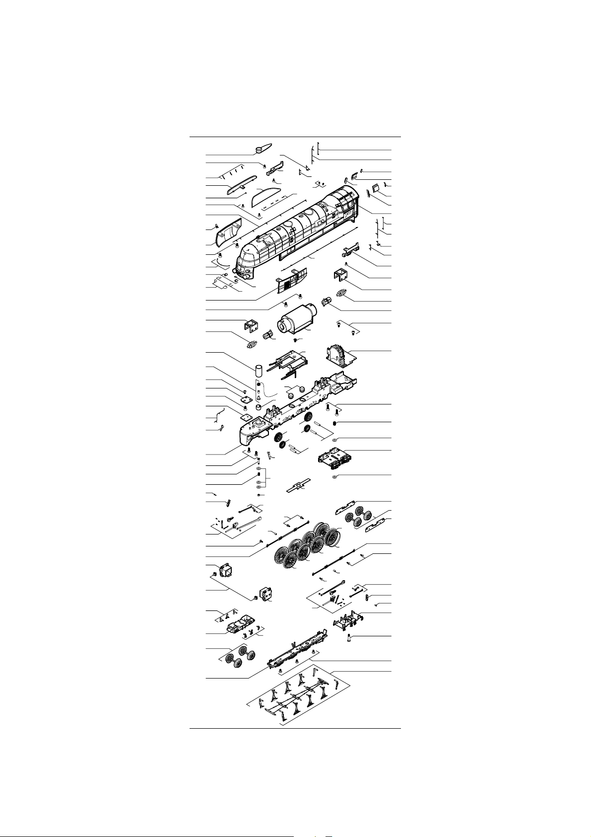
Ersatzteilliste
Spare Parts List
6
13
16
2
140
14
24
15
4
18
142
28
26
5
18
32
30
48
46
43
41
42
44
51
49
38
36
76
75
63
62
58
55
56
64
67
79
27
22
11
52
53
16
86
59
17
40
47
39
54
87
21
29
25
88
9
89
90
78
55
18
3
99
31
141
45
49
69
138
60
55
78
65
19
20
8
7
8
7
10
1
19
20
23
21
12
18
32
30
31
33
34
37
68
69
70
69
71
85
72
57
55
61
62
63
73
77
84
81
80
74
82
83
14
Page 15

95
143
96
99
101
27
100
102
94
93
92
91
124
97
98
107
108
114
115
118
119
121
120
123
125
139
129
137
129
131
110
111
112
109
113
117
116
117
122
139
126
127
128
136
128
132
130
133
134
135
144
15
Page 16

Ersatzteilliste
Pos. Bestell-Nr. Benennung
1 0636.50.01 Gehäuse kpl.
2 0636.50.02 Windleitblech rechts
3 0636.50.03 Windleitblech links
4 0636.50.04 Seitenteil rechts
5 0636.50.05 Seitenteil links
6 0636.50.06 Schornstein
7 0630.50.07 Seitenfenster
8 0630.50.08 Windabweiser
9 0630.50.09 Frontscheibe rechts
10 0630.50.10 Frontscheibe links
11 0630.50.11 Blende rechts Fahrgestell
12 0630.50.12 Blende links Fahrgestell
13 0630.50.13 Schraube für Schornstein
14 0630.50.14 Schraube für Windleitblech
15 0630.50.15 Pfeife
16 0630.50.16 Halter für Windleitblech
17 0630.50.17 Sicherheitsventil
18 0630.50.18 Schraube für Seitenteil
19 0630.50.19 Griffstange
20 0630.50.20 Griffstange lang
21 0630.50.21 Griffstange kurz
22 0630.50.22 Griffstange rechts gebogen
23 0630.50.23 Griffstange links gebogen
24 0630.50.24 Griffstange Kessel rechts
25 0630.50.25 Griffstange Kessel links
26 0630.50.26 Lampenglas links und rechts
27 3268.99.00 Glühlampen
28 0630.50.27 Hülsen für Glühlampen
29 0630.50.28 Motor kpl.
30 0630.50.29 Schnecke kpl.
31 0630.50.30 Kardan kpl.
32 0630.50.31 Halterung für Schnecke
33 0630.50.32 Schraube Inneneinrichtung
34 0630.50.33 Inneneinrichtung
36 0630.50.35 Gehäuseschraube vorn
37 0630.50.36 Gehäuseschraube hinten
38 0630.50.37 Rahmen kpl.
39 0630.50.38 Steuerungsträger kpl.
40 0630.50.39 Schraube für Steuerungsträger
41 0630.50.40 Lampenplatine
42 0630.50.41 Schraube für Platine
43 0630.50.42 Schraube für Kontaktplatine
44 0630.50.43 Kontaktplatine
45 0630.50.44 Hülse
46 0630.50.45 Kabel für Rauchgenerator kpl.
47 0630.50.46 Blattfeder
48 0630.50.47 Einsatz für Rauchgenerator
49 0630.50.48 Schienenräumer
51 0630.50.50 Leitung kpl.
52 0630.50.51 Zahnrad groß
53 0630.50.52 Zahnrad klein
54 0630.50.53 Achse
55 0630.50.54 Sechskantschraube
56 0630.50.55 Kuppelstange rechts
57 0630.50.56 Kuppelstange links
58 0630.50.57 Gestänge rechts
59 0630.50.58 Gestänge links
60 0630.50.59 Kurbelzapfen kpl. rechts
61 0630.50.60 Kurbelzapfen kpl. links
62 0630.50.61 Wipphebel
63 0630.50.62 Splint
64 0630.50.63 Zylinder rechts
65 0630.50.64 Zylinder links
67 0630.50.66 Abdeckung für Zylinder
16
Page 17

Pos. Bestell-Nr. Benennung
68 0630.50.67 Druckfeder hinten
69 0630.50.68 Scheibe
70 0630.50.69 Drehgestell hinten
71 0630.50.70 Stromabnahmeblech rechts DC
72 0630.50.71 Stromabnahmeblech links DC
73 0630.50.72 Bremseinheit kpl. hinten
74 0630.50.73 Distanzschraube hinten
75 0630.50.74 Druckfeder vorn
76 0630.50.75 Distanzschraube vorn
77 0630.50.76 Drehgestell kpl. vorn
78 0630.50.77 Distanzhülse
79 0630.50.78 Bremsbacken kpl. rechts
80 0630.50.79 Bremsbacken kpl. links
81 0630.50.80 Getriebeabdeckung kpl.
82 0630.50.81 Schraube Getriebeabdeckung
83 0630.50.82 Bremsgestänge kpl.
84 0630.50.83 Radsatz Vorlauf DC
0631.50.83 Radsatz Vorlauf AC
85 0630.50.84 Radsatz Nachlauf DC
0631.50.84 Radsatz Nachlauf AC
86 0630.50.85 1. Kuppelradsatz DC
0631.50.85 1. Kuppelradsatz AC
87 0630.50.86 2. Kuppelradsatz DC
0631.50.86 2. Kuppelradsatz AC
88 0630.50.87 3. Kuppelradsatz DC
0631.50.87 3. Kuppelradsatz AC
89 0630.50.88 4. Kuppelradsatz DC
0631.50.88 4. Kuppelradsatz AC
90 0630.50.89 Haftreifen
91 0636.50.90 Gehäuse Tender kpl.
92 0636.50.91 Blende Tender rechts
93 0636.50.92 Blende Tender links
94 0630.50.93 Griffstangen Tender
95 0636.50.94 Deckel Tender
96 0630.50.95 Lokschild (Tender)
97 0630.50.96 Puffer gewölbt
98 0630.50.97 Puffer gerade
99 0630.50.98 Griffstange klein
100 0630.50.99 Lampenglas
101 0630.50.100 Hülse für Lampe Tender
102 0630.50.101 Leiter
107 0630.50.106 Platine für Licht
108 0630.50.107 Schraube für Platine
109 0630.50.108 Platine
110 0630.50.109 Schraube
111 0630.50.110 Schraube für Transistor
112 0530.99.34 Blindstecker
113 0630.50.111 Gewicht Tender
114 0630.50.112 Abdeckung Kinematik
115 0630.50.113 Kinematik
116 0630.50.114 Deichsel kpl.
117 0630.50.115 Feder für Deichsel
118 0630.50.116 Schraube für Kinematik
119 0630.50.117 Abdeckung für Kurzkupplung
120 0630.50.118 Normschacht
121 0630.50.119 Feder für Normschacht
122 0630.50.120 Rahmen kpl. Tender
123 9952.50.03 Bügelkupplung
124 9750.50.00 Premium-Digitaldecoder- AC
125 0630.50.121 Schienenräumer
126 0630.50.122 Abdeckung
127 0630.50.123 Feder
128 0630.50.124 Stromabnehmer klein DC
129 0630.50.125 Stromabnehmer groß DC
17
Page 18

Ersatzteilliste
Spare Parts List
Pos. Bestell-Nr. Benennung
130 0630.50.126 Drehgestell klein
131 0630.50.127 Drehgestell groß
132 0630.50.128 Lagerschraube
133 0630.50.129 Lagerschraube
134 2225 Schleifer AC
135 0631.50.131 Schraube für Schleifer DC
136 0630.50.132 Tender-Radsatz DC
0631.50.132 Tender-Radsatz AC
137 0630.50.133 Tender-Radsatz DC
0631.50.133 Tender-Radsatz AC
138 0630.50.134 Mutter
139 0630.50.135 Schraube für Gehäuse
140 0630.50.136 Signalhalter
141 0630.50.137 Gummipuffer Motorhalter
142 0630.50.138 Griffstangen gebogen
143 0630.50.139 Signalhalter Tender
144 0630.50.140 Zurüstbeutel
Bestellbeispiel:
Pfeife mit Position 15 = 0630.50.15 Pfeife
Wichtiger Hinweis!
Bei der Bestellung von Ersatzteilen muss die Bestell-Nr.
und die Benennung angegeben werden. Ist dies nicht der Fall,
kann die Bestellung nicht bearbeitet werden.
Pos. Order no. Description
1 0636.50.01 Body cpl.
2 0636.50.02 Spoiler right
3 0636.50.03 Spoiler left
4 0636.50.04 Sidepart right
5 0636.50.05 Sidepart left
6 0636.50.06 Chemney
7 0630.50.07 Cabinside windowglas
8 0630.50.08 Windshield
9 0630.50.09 Window front right
10 0630.50.10 Window front left
11 0630.50.11 Cover right
12 0630.50.12 Cover left
13 0630.50.13 Screw for chemney
14 0630.50.14 Screw for Spoiler
15 0630.50.15 Whistle
16 0630.50.16 Holder for Spoiler
17 0630.50.17 Safety valve right
18 0630.50.18 Screw
19 0630.50.19 Handrail
20 0630.50.20 Handrail long
21 0630.50.21 Handrail short
22 0630.50.22 Handrail right Bended
23 0630.50.23 Handrail left Bended
24 0630.50.24 Handrail boiler right
25 0630.50.25 Handrail boiler left
26 0630.50.26 Lampglas
27 3268.99.00 Bulbs
28 0630.50.27 Cover for Bulb
29 0630.50.28 Motor cpl.
30 0630.50.29 Worm
31 0630.50.30 Cardan cpl.
32 0630.50.31 Worm cover
33 0630.50.32 Screw
34 0630.50.33 Interior
36 0630.50.35 Screw
18
Page 19

Pos. Order no. Description
37 0630.50.36 Screw
38 0630.50.37 Main frame
39 0630.50.38 Control support
40 0630.50.39 Screw
41 0630.50.40 PCB for bulbs
42 0630.50.41 Screw
43 0630.50.42 Screw
44 0630.50.43 PCB for Frontlight
45 0630.50.44 Washer
46 0630.50.45 Contact pin
47 0630.50.46 Axel spring
48 0630.50.47 Electric muff
49 0630.50.48 Rear right Side track
51 0630.50.50 Hose
52 0630.50.51 Gear wheel big
53 0630.50.52 Gear wheel small
54 0630.50.53 Axle
55 0630.50.54 Screw for wheel
56 0630.50.55 Couple rod right
57 0630.50.56 Couple rod left
58 0630.50.57 Rods right
59 0630.50.58 Rods left
60 0630.50.59 Rods right
61 0630.50.60 Rods left
62 0630.50.61 Expansion link
63 0630.50.62 Pin
64 0630.50.63 Cylinder right
65 0630.50.64 Cylinder left
67 0630.50.66 Separate part for cylinder
68 0630.50.67 Spring for rear bogie
69 0630.50.68 Washer
70 0630.50.69 Rear bogie
71 0630.50.70 Pick-up rear bogie right DC
72 0630.50.71 Pick-up rear bogie left DC
73 0630.50.72 Rear bogie brake block
74 0630.50.73 Screw for rear bogie
75 0630.50.74 Spring for front bogie
76 0630.50.75 Screw for front bogie
77 0630.50.76 Front bogie
78 0630.50.77 Washer
79 0630.50.78 Brake right Front bogie
80 0630.50.79 Brake left Front bogie
81 0630.50.80 Frame basic plate
82 0630.50.81 Screw
83 0630.50.82 Brake linkage
84 0630.50.83 Wheelset DC
0631.50.83 Wheelset AC
85 0630.50.84 Wheelset DC
0631.50.84 Wheelset AC
86 0630.50.85 1. Wheelset DC
0631.50.85 1. Wheelset AC
87 0630.50.86 2. Wheelset DC
0631.50.86 2. Wheelset AC
88 0630.50.87 3. Wheelset DC
0631.50.87 3. Wheelset AC
89 0630.50.88 4. Wheelset DC
0631.50.88 4. Wheelset AC
90 0630.50.89 Traction tire
91 0636.50.90 Body Tender
92 0636.50.91 Sliding flap right
93 0636.50.92 Sliding flap left
94 0630.50.93 Handrail tender
95 0636.50.94 Cover for tender
96 0630.50.95 Number plate
19
Page 20

Spare Parts List
Pos. Order no. Description
97 0630.50.96 Buffer round
98 0630.50.97 Buffer flat
99 0630.50.98 Handrail small
100 0630.50.99 Lamp glass
101 0630.50.100 Cover for bulb
102 0630.50.101 Backleather
107 0630.50.106 PCB for bulb
108 0630.50.107 Screw
109 0630.50.108 PCB
110 0630.50.109 Screw
111 0630.50.110 Screw
112 0530.99.34 Blind plug
113 0630.50.111 Weight for tender
114 0630.50.112 Cover for coupler pocket
115 0630.50.113 Coupler pocket
116 0630.50.114 Connecting plate
117 0630.50.115 Spring
118 0630.50.116 Screw
119 0630.50.117 Cover connecting plate
120 0630.50.118 Coupler pocket
121 0630.50.119 Spring for coupler pocket
122 0630.50.120 Main frame tender
123 9952.50.03 Coupler
124 9750.50.00 Premium digital decoder AC
125 0630.50.121 Front right side track cleaner
126 0630.50.122 Cover
127 0630.50.123 Spring
128 0630.50.124 Pick-up small DC
129 0630.50.125 Pick-up large DC
130 0630.50.126 Bogie tender small
131 0630.50.127 Bogie tender large
132 0630.50.128 Screw
133 0630.50.129 Screw
134 2225 Pick-up shoe
135 0631.50.131 Screw for pick-up shoe
136 0630.50.132 Wheelset Tender DC
0631.50.132 Wheelset Tender AC
137 0630.50.133 Wheelset Tender DC
0631.50.133 Wheelset Tender AC
138 0630.50.134 Nut
139 0630.50.135 Screw
140 0630.50.136 Signal holder
141 0630.50.137 Motor bearing
142 0630.50.138 Handrail bended
143 0630.50.139 Signal holder Tender
144 0630.50.140 Add-on bag
Order example:
Whistle with position 15 = 0630.50.15 Whistle
Important notice!
When ordering spare parts you must always state the order number
and give the description. If you do not do this, the order cannot be
processed.
Brawa Modellspielwarenfabrik GmbH + Co.
Uferstraße 26-28 · D-73630 Remshalden
Telefon +49 (0)7151 - 97 93 50
Telefax+49 (0)7151 - 7 46 62
http://www.brawa.de
20
0636.50.145 / 04 5 01 - WAN
 Loading...