

Page 1
Betriebsanleitung
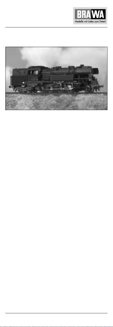
Dampflokomotive BR 6510 – H0
Ausführung Gleichstrom 0612
Ausführung Wechselstrom 0613
Die Deutsche Reichsbahn in der DDR plante ab 1951, ihren überalterten Lokpark langfristig zu erneuern. Dabei sollten auch Dampflokomotiven den alten Bestand ergänzen. 1952 wurde ein Bauprogramm
aufgestellt, das sieben verschiedene Loktypen enthielt.
Vier Typen des Programms wurden tatsächlich realisiert. In der Leistungsklasse der ehemals preußischen P 8 und T 18 entstand die
Tenderlok der Baureihe 6510.
1954 verließ die erste Lokomotive 65 1001 die Werkhallen von LEW
Hennigsdorf. Da ihre Konstruktion letztlich auf einem Entwurf der
Firma Borsig aus dem Jahr 1946 basierte, erhielt sie eine Borsig Fabriknummer. Parallel zu den Versuchsfahrten der ersten Prototypen lief
bereits der Serienbau bei Lokomotivbau „Karl Marx“ in Babelsberg.
Diese Situation erschwerte das Ausmerzen von konstruktionsbedingten „Kinderkrankheiten“ erheblich.
Bis 1957 wurden insgesamt 93 Lokomotiven gebaut. Dann begann
sich der Strukturwandel zur elektrischen – und Dieseltraktion auch in
der DDR abzuzeichnen.
Die Lokomotiven blieben bis auf wenige Ausnahmen bis 1975 im
Einsatz. Sie fuhren besonders häufig im Berufsverkehr mit kurzen
Haltestellenabständen, da sie hier mit ihrer guten Beschleunigung
überzeugten. Die maximale Höchstgeschwindigkeit betrug 90 km/h,
das Dienstgewicht 113 t. Nur drei Exemplare der Baureihe haben
bis heute überlebt. Das direkte Vorbild des Brawa-Modells ist die
BR 65 1016.
1
Page 2

Locomotive BR 6510 – H0
Locomotive BR 6510 – H0
Operating Instructions
Direct current model 0612
Alternating current model 0613
From 1951 onwards Deutsche Reichsbahn – the German State Railway
of the GDR (former East Germany) – planned the long-term renewal
of its stock of locomotives. The old stock was also to be complemented with steam engines. In 1952 a programme was set up that
envisaged seven different types of locomotives.
Four types from this programme were actually built. The 6510 series
tank locomotive was based on the former Prussian P 8 and T 18
performance class.
The first locomotive, the 65 1001, left the LEW Hennigsdorf works in
1954. It was given a Borsig factory number because its design was
based on a concept of the Borsig company dating back to 1946. Series
production at Lokomotivbau “Karl Marx” in Babelsberg proceeded
parallel with the trial runs of the first prototypes. This situation made
it more difficult to eradicate design-based “teething problems”.
A total of 93 locomotives were built up to 1957. At this point a structural change towards electrical and diesel traction became apparent
in the GDR.
With a few exceptions all locomotives remained in service right up to
1975. On account of their excellent acceleration characteristics, they
were often used on commuter routes where the distances between
the individual stations were short. The locomotive’s maximum speed
was 90 km/h, and it had a service weight of 113 t. Only three models
of this series have survived to this day. The Brawa version was directly
modelled on the basis of the BR 65 1016 concept.
Instructions de service
Modèle à courant continu 0612
Modèle à courant alternativ 0613
Les Chemins de fer allemands (Deutsche Reichsbahn) de l’ex-R.D.A.
avaient prévu à partir de 1951 le renouvellement à long terme de leur
parc de locomotives qui était vétuste. Ce faisant, on pensait compléter
également le vieux parc de locomotives à vapeur. Un programme de
construction a été élaboré en 1952. Il se composait de sept types de
locomotives différentes.
Quatre types du programme ont abouti et furent réalisés. Dans la
catégorie des anciennes locomotives prussiennes P 8 et T 18, on
créa la locomotive-tender de la série de fabrication 6510.
La première locomotive 65 1001 quitta en 1954 les halles d’usine de
LEW Hennigsdorf. Puisque sa construction partait d’un plan issu de
l’entreprise Borsig de l’année 1946, elle reçut un numéro d’usine
Borsig. Parallèlement aux essais effectués sur les premiers prototypes,
la construction en série commençait déjà dans l’usine de construction
de locomotives “Karl Marx” à Babelsberg. Cette situation compliqua
considérablement l’élimination des “défauts de jeunesse” dus à la
construction.
On construisit 93 locomotives au total jusque 1957. C’est alors que
le changement structurel s’annonça en R.D.A. aussi, on passa à la
traction électrique – et au moteur à diesel.
Les locomotives furent mobilisées, à part quelques exceptions, jusque
2
Page 3
Locomotiva BR 6510 – H0
1975. Elles circulaient assez souvent aux heures de pointe, s’arrêtant
à de courtes distances, car leur bonne capacité d’accélération était
convaincante dans ces cas-là. La vitesse maximale atteinte s’élevait
à 90 km/h, son poids de service était de 113 t. Trois exemplaires
seulement de cette série ont survécu jusque de nos jours. Le modèle
dont cette locomotive Brawa est directement inspirée, est la locomotive BR 65 1016.
Istruzioni sul funzionamento
Versione a corrente continua 0612
Versione a corrente alternata 0613
Nella Repubblica Democratica Tedesca, a partir e dal 1951 le Deutsche
Reichsbahn programmarono di rinnovare a lunga scadenza il loro
obsoleto parco locomotive. In questa occasione il vecchio parco
doveva essere integrato anche da locomotive a vapore. Nel 1952
venne stabilito un programma di produzione contenente sette diversi
tipi di locomotive.
Quattro modelli furono effettivamente costruiti. Nell’ordine delle
prestazioni delle ex prussiane P 8 e T 18, fu costruita la locomotivatender serie 6510.
Nel 1954, la prima locomotiva 65 1001 lasciò le officine della LEW
di Hennigsdorf. Poiché la sua struttura in fondo era basata su un
progetto della ditta Borsig dell’anno 1946, essa ricevette un numero
di costruzione della Borsig. Contemporaneamente alle corse di prova
dei primi prototipi, presso la fabbrica di locomotive “Karl Marx” di
Babelsberg era già in corso la produzione in serie. Questa situazione
rese notevolmente difficile l’eliminazione delle “malattie infantili”
dovute alla costruzione.
Fino al 1957 furono costruite in totale 93 locomotive. Successivamente anche nella RDT iniziò a delinearsi il passaggio alla trazione
elettrica e Diesel.
Escluse poche eccezioni, le locomotive rimasero in servizio fino al
1975. Vennero impiegate molto spesso nel trasporto dei pendolari
con brevi distanze tra le fermate, poiché convincevano per la loro
buona accelerazione. La velocità massima era di 90 km/h e il peso in
esercizio di 113 t. Solo 3 esemplari della serie sono sopravvissuti
fino ad oggi. Il modello Brawa ha preso direttamente spunto dalla
BR 65 1016.
3
Page 4

Inhaltsverzeichnis
Contents
Benennung Seite
Allgemeine Hinweise ..................................................................... 5
Entnahme der Lok aus der Verpackung ......................................... 6
Zusatzbauteile montieren............................................................... 7
Wartungsarbeiten
• 1. Ölen....................................................................................... 8
• 2. Seuthe Raucheinsatz montieren ............................................ 8
• 3. Umrüsten auf Digitalbetrieb .................................................. 9
• 4. Gehäuse demontieren ......................................................... 10
• 5. Platine tauschen.................................................................. 10
• 6. Motor tauschen ................................................................... 10
• 7. Umschaltrelais tauschen ..................................................... 10
• 8. Haftreifen tauschen ............................................................. 10
• 9. Schleifer tauschen bei Wechselstrom-Ausführung.............. 10
• 10. Glühbirne tauschen ........................................................... 10
• 11. Wartungsarbeiten am Kupplungsnormschacht ................. 10
• 12. Wartungsarbeiten an Radsätze und Getriebe..................... 10
Ersatzteilliste
Gleichstrom- und Wechselstrom-Ausführung ........... 14, 15, 16, 17
Bestellbeispiel........................................................................ 15, 17
Description Page
General information....................................................................... 5
Removing the locomotive from the packaging .............................. 6
Fitting additional parts ................................................................... 7
Maintenance works
• 1. Lubricating ............................................................................ 8
• 2. Mounting the Seuthe smoke insert ....................................... 8
• 3. Conversion to digital operating ............................................. 9
• 4. Dismantling the housing ..................................................... 12
• 5. Exchanging the circuit board............................................... 12
• 6. Exchanging the engine ........................................................ 12
• 7. Exchanging the change-over relay ...................................... 12
• 8. Exchanging the traction tires............................................... 12
• 9. Exchanging the sliding contact, alternating current............. 12
• 10. Exchanging the bulb.......................................................... 12
• 11. Maintenance work on the front
standard coupling shaft ..................................................... 12
• 12. Maintenance work on wheelsets and gear......................... 12
Spare parts list
direct current and alternating current ........................ 14, 15, 18, 19
Order example ....................................................................... 15, 19
4
Page 5
Allgemeine Montage- und Sicherheitshinweise
• Diese Bedienungsanleitung beschreibt sämtliche Arbeitsvorgänge
die zur Wartung und Instandhaltung notwendig sind.
Bitte lesen Sie diese Bedienungsanleitung bevor Sie
mit den Arbeiten beginnen.
• Bei unsachgemäßem Umgang mit elektrischen Bauteilen können
diese zerstört werden. Für entsprechende Arbeiten
(z.B. Platinenwechsel) können Sie sich an Ihren Fachhändler
oder den Hersteller wenden.
• Bei den folgenden Wartungsarbeiten ist die jeweilige Demontage
beschrieben, der Zusammenbau ist in umgekehrter Reihenfolge
auszuführen.
• Die folgenden Wartungsarbeiten sind bei Gleich- und Wechselstrom-Ausführungen fast identisch. Im Ausnahmefall wird im
entsprechenden Textabschnitt Bezug genommen.
General assembly and safety information
• These operating instructions describe all work steps necessary
for maintenance and repair. Please read these operating
instructions carefully before you start with your work.
• In the case of incorrect handling of electrical components, they
may be destroyed. Please ask your specialist dealer to help with
the necessary work (e.g. changing circuit boards).
• In the case of maintenance work, the disassembly is described
below, to re-assemble the tractor reverse the work steps.
• The maintenance work described below is virtually identical for
direct current and alternating current models. If there are any
differences these will be pointed out specifically.
5
Page 6
Arbeiten vor der Inbetriebnahme
Work to be performed before starting up
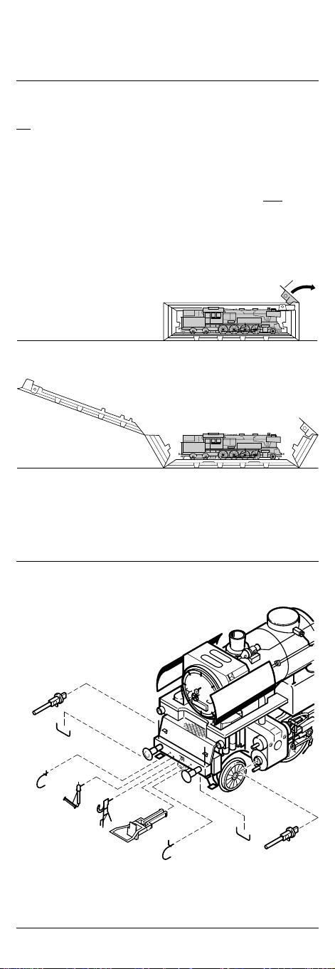
Entnahme der Lok aus der Verpackung (Fig. 1)
Deckel der Verpackung öffnen. Kunststoff-Schutzverpackung
mit Lok entnehmen und auf einen Tisch oder ähnliches abstellen.
Lasche (1) lösen, Deckel und Seitenteile der Schutzverpackung
wegklappen, Lok entnehmen.
Withdrawal of Engine from Packaging (Fig. 1)
Open package lid. Take out plastics protecting package with
engine and put it down on a table or similar item. Loosen latch (1),
fold away lid and side parts of protecting package, take out engine.
Fig. 1
1
Fig. 2
8
4
7
6
5
1
3
6
7
8
Page 7
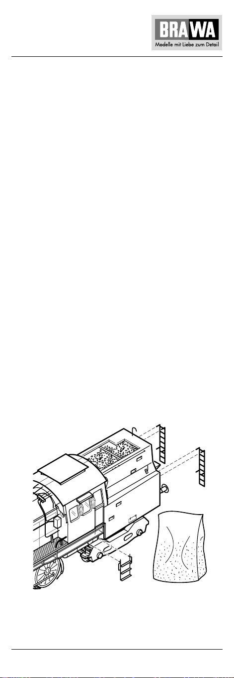
Zusatzbauteile montieren (Fig. 2)
In der Verpackung sind zusätzliche Bauteile lose beigelegt.
• 1 = 2 x Bügelkupplung
2 = 1 x Beutel mit echter Kohle zum Auffüllen des Kohletenders
• Werden die Bauteile aus dem Zurüstbeutel für Vitrinenmodelle
montiert, ist die Lok nicht mehr für den Fahrbetrieb geeignet.
3 = 2 x Bremsschlauch, links
4 = 2 x Bremsschlauch, rechts
5 = 2 x Kupplungsimitat
6 = 2 x Heizschlauch
7 = 4 x Griffstangen Pufferbohlen
8 = 2 x Kolbenstangenhülse
9 = 2 x Aufstiegsleiter seitlich
10 = 2 x Aufstiegsleiter hinten
Fitting additional parts (Fig. 2)
Accessory parts have been loosely enclosed in the packaging.
• 1 = 2 x bow coupling
2 = 1 x bag with real coal to fill the tender
• If the components from the add-on bag for display models are
mounted, then the engine will no longer be suitable for operation.
3 = 2 x Air-brake hose, left
4 = 2 x Air-brake hose, right
5 = 2 x Imitation coupling
6 = 2 x Heating hose
7 = 4 x Handrail buffer beams
8 = 2 x Piston rod sleeve
9 = 2 x Side ladder
10 = 2 x Rear ladder
Fig. 2
10
9
7
2
Page 8
Wartungsarbeiten
Maintenance works
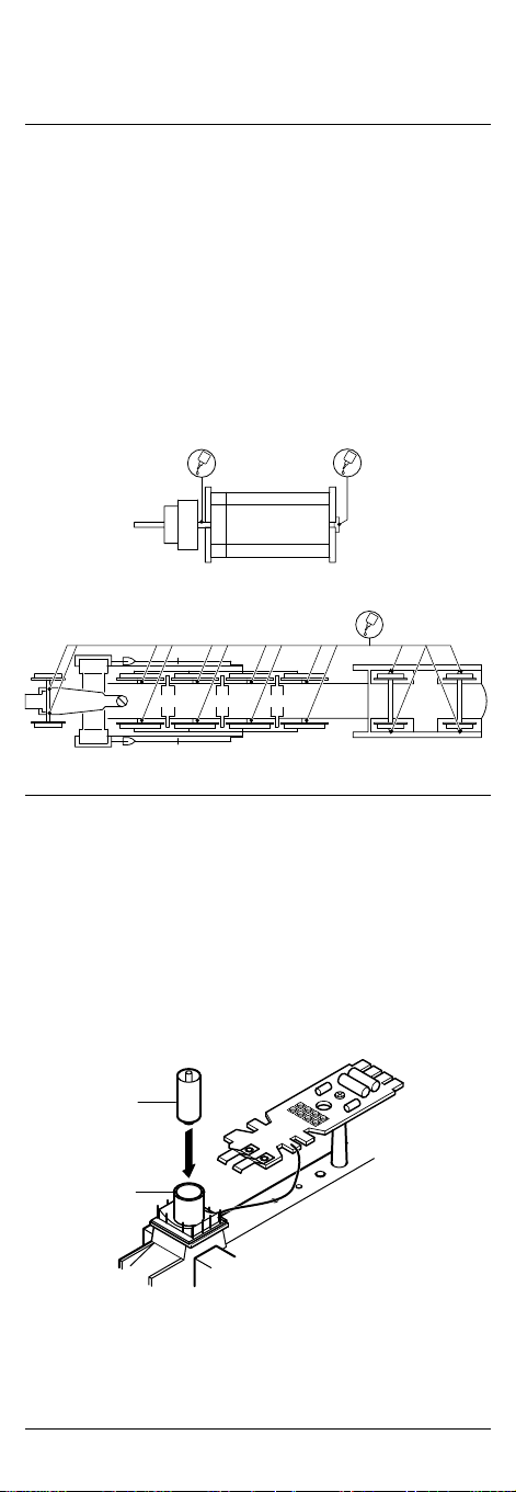
1. Ölen (Fig. 3)
Der Motor und die Lagerstellen der Radsätze können an den
gekennzeichneten Punkten sparsam mit Öl der Modellbaubranche
geölt werden. Zum Ölen des Motors ist das Gehäuse abzunehmen,
siehe Seite 10 Punkt 4.
1. Lubricating (Fig. 3)
The engine and the wheelset bearings may be sparingly lubricated
at the marked places with oil used for model making purposes.
In order to lubricate the engine, remove the housing, compare page
12, item 4.
Fig. 3
Motor
Engine
Räder
Wheels
2. Seuthe Raucheinsatz montieren (Fig. 4)
Gehäuse abnehmen, siehe Punkt 4 Seite 10.
Raucheinsatz (1) in Hülse (2) einsetzen und Gehäuse montieren.
2. Mounting the Seuthe smoke insert (Fig. 4)
Remove housing, compare item 4, page 12.
Place the smoke insert (1) in the sleeve (2) and mount the housing.
Fig. 4
1
2
8
Page 9
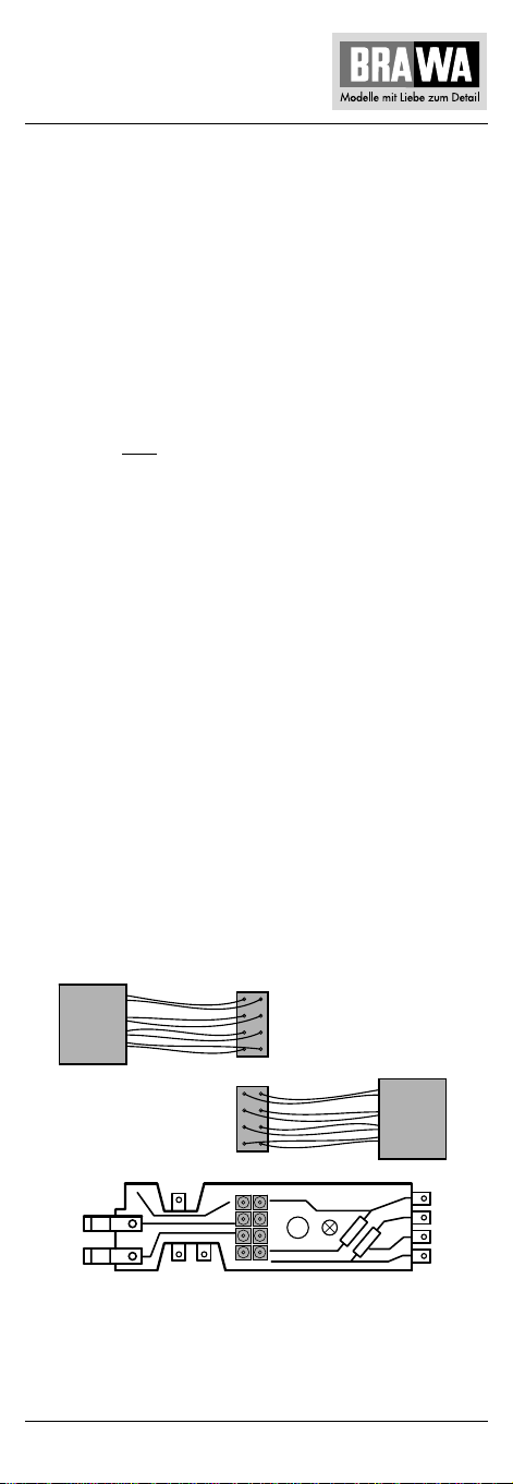
3. Umrüsten und Umprogrammieren
auf Digitalbetrieb (Fig. 5 und Seite 10 Fig.6)
Wechselstrom-Ausführung AC 0613
Lokomotiven in Wechselstrom-Ausführung AC werden serienmäßig
mit Digitaldecoder für den analogen Betrieb ausgeliefert. Wird die
Lokomotive digital betrieben, muss der Digitaldecoder anhand der
beiliegenden Betriebsanleitung „Digitaldecoder AnDi 75 3...“
umprogrammiert werden.
Gleichstrom-Ausführung DC 0612
Gehäuse demontieren, siehe Seite 10, Punkt 4. Blindstecker (3)
abziehen und Digitaldecoder einstecken. Den richtigen Einbau des
Digitaldecoders, dessen Einsteckrichtung und Programmierung
entnehmen Sie der Betriebsanleitung des Decoderherstellers.
Nach Einstecken des Digitaldecoders ist die Funktion des Lichtes zu
prüfen. Wenn keine Lichtfunktion – Stecker um 180° drehen.
3. Conversion and reprogramming
to digital operating (Fig. 5 and page 12, Fig. 6)
Alternating current version AC 0613
Engines of the alternating current version AC are supplied with
digital decoder for analog operation as a standard. If the engine is
operated in digital mode, the digital decoder has to be reprogrammed in accordance with the enclosed operating instructions
‘digital decoder AnDI 75 3...’.
Direct current version DC 0612
Remove housing, compare page 12, item 4. Pull off the dummy
plug (3) and plug in the digital decoder. For the correct installation
of the digital decoder, the direction in which to plug it in and how
to programme it, please refer to the mounting instructions of the
decoder manufacturer. Once the digital decoder has been plugged
in, it must be checked whether the light is working. If the light does
not function, turn the plug by 180°.
Fig. 5
Einsteckrichtung
Plug-in direction
AC
digital
AC = Wechselstrom
DC = Gleichstrom
AC = Alternating Current
DC = Directed Current
DC
digital
9
Page 10

Wartungsarbeiten
4. Gehäuse demontieren (Fig. 6)
Schraube (1) an der Gehäuseunterseite herausdrehen, Haltelaschen
(2) durch leichtes drücken in Pfeilrichtung ausclipsen, Gehäuse
vorsichtig nach oben abziehen.
5. Platine tauschen (Fig. 6)
Gehäuse abnehmen, siehe Punkt 4.
Blindstecker (3) bei DC-Ausführung oder Umschaltrelais (4) bei ACAusführung abziehen. Sämtliche Kabel an der Platine (5) ablöten.
Bitte kennzeichnen Sie sich wo die einzelnen Kabel angelötet waren.
Befestigungsschrauben (6) herausdrehen, Platine nach oben
abnehmen.
6. Motor tauschen (Fig. 6)
Gehäuse abnehmen, siehe Punkt 4.
Motor mit Motorhalterung (7) mittels Schraubendreher nach oben
anheben, dabei werden die Motorlagerungen (8) ausgeknöpft.
Kabel (9) ablöten.
Hinweis:
Beim Einbau des neuen Motors muss die Kardanwelle (10) in die
Schwungmasse (11) eingesetzt und die Gummitülle (12) über die
Lötstelle geschoben werden.
7. Umschaltrelais tauschen (Fig. 6)
Umschaltrelais (4) abziehen und neues einstecken.
8. Haftreifen tauschen (Fig. 6)
Sechskantschraube SW 2,5 (13) der Kuppelstange herausdrehen
und Haftreifen (14) wechseln.
9. Schleifer tauschen bei Wechselstrom-
Ausführung (Fig. 6)
Befestigungsschraube (15) des Schleifers (16) herausdrehen,
Kabel ablöten und Schleifer abnehmen.
10. Glühbirnen tauschen (Fig. 6)
Gehäuse abnehmen, siehe Punkt 4.
Kabel der defekten Glühbirne an Lichtplatine ablöten. Glühbirne mit
Lampenfassung aus Lampengehäuse herausziehen. Glühbirne mit
Kabel aus Lampenfassung (17) nach vorn herausziehen. Einbau in
umgekehrter Reihenfolge.
11. Wartungsarbeiten am Kupplungsnormschacht
(Fig. 6)
Kupplungsnormschacht vorn:
Befestigungsschraube (18) herausdrehen, Vorlaufachse mit
Kupplungsnormschacht (19) abnehmen.
Kupplungsnormschacht hinten:
Drehgestell (20) seitlich ausschwenken, Haltebügel (21) ausclipsen,
Kupplungsnormschacht (22) entnehmen.
12. Wartungsarbeiten an Radsätze, Getriebe
(Fig. 6)
Bei Wartungsarbeiten an den Radsätzen (23), dem Kuppelgestänge
(24) und dem Getriebe muss das gesamte Fahrgestell zerlegt
werden. Wir bitten Sie bei der Demontage des Fahrgestells genau
darauf zu achten, wo und wie jedes Einzelteil montiert war.
Die Einbaulage können Sie auch aus der Ersatzteilgrafik Seite 14, 16
ersehen. Vor dem Zerlegen des Fahrgestells müssen Gehäuse und
Platine demontiert werden (siehe Punkt 4 und 5).
10
Page 11
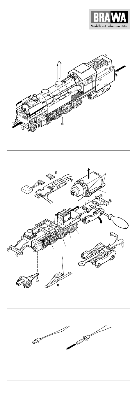
Fig. 6
2
2
1
19
6
3
4
5
24
16
18
15
23
11
14
10
7
8
13
17
9
12
20
21
22
11
Page 12

Maintenance works
4. Dismantling the housing (Fig. 6)
Remove the screw (1) on the underside of the housing. Unclip the
holding straps (2) by lightly pressing them in the direction of the
arrow. Carefully lift off the housing (3).
5. Exchanging the circuit board (Fig. 6)
Remove the housing; see 4.
Withdraw the blind plug (3) of the DC version or the change-over
relay (4) of the AC version. Unsolder all cables on the circuit board
(5). Please identify the points were the individual cables were
soldered. Unscrew the fastening screws (6). Lift out the circuit
board.
6. Exchanging the engine (Fig. 6)
Remove the housing; see 4.
Raise the engine with engine holder (7) with a screwdriver and
unclip the engine bearings (8). Unsolder the cable (9).
Note:
When mounting the new engine the cardan shaft (10) must be
inserted in the flywheel (11), and the rubber sleeve (12) must be
pushed over the soldered point.
7. Exchanging the change-over relay (Fig. 6)
Withdraw the change-over relay (4) and insert the new one.
8. Exchanging the traction tires (Fig. 6)
Unscrew the SW 2.5 hexagon screw (13) of the crank shaft and
exchange the traction tyres (14).
9. Exchanging the sliding contact of the alternatingcurrent version (Fig. 6)
Unscrew the fastening screw (15) of the sliding contact (16).
Unsolder the cable. Remove the sliding contact.
10. Exchanging the bulb (Fig. 6)
Remove the housing; see 4.
Unsolder the cable of the defective bulb on the circuit board.
Remove the bulb with bulb socket from the bulb housing. Lift the
bulb with cable out of the bulb socket (17). Reverse the sequence to
return the new bulb.
11. Maintenance work on the front standard
coupling shaft (Fig. 6)
Front standard coupling shaft:
Unscrew the fastening screw (18). Remove the lead axle with
standard coupling shaft (19).
Rear standard coupling shaft:
Swivel out the bogie (20) sideways. Unclip the holding strap (21).
Remove the standard coupling shaft (22).
12. Maintenance work on the wheelsets and gear
(Fig. 6)
The entire chassis must be dismantled for maintenance work on the
wheelsets (23), the coupling rods (24) and the transmission gear.
Please note exactly where each part was mounted when the chassis
is being dismantled.
The mounting position is also indicated on the spare parts graph
on page 14, 18. The housing and the circuit board (see section 4
and 5) must be removed before the chassis can be dismantled.
12
Page 13
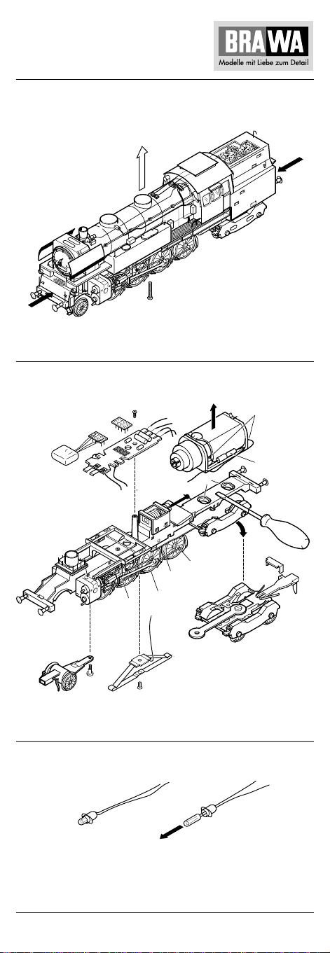
Fig. 6
2
2
1
19
6
3
4
5
24
16
18
15
23
11
14
10
7
8
13
17
9
12
20
21
22
13
Page 14
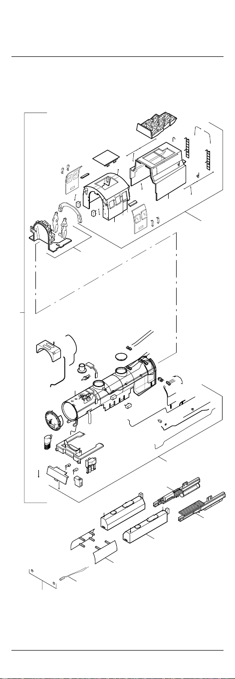
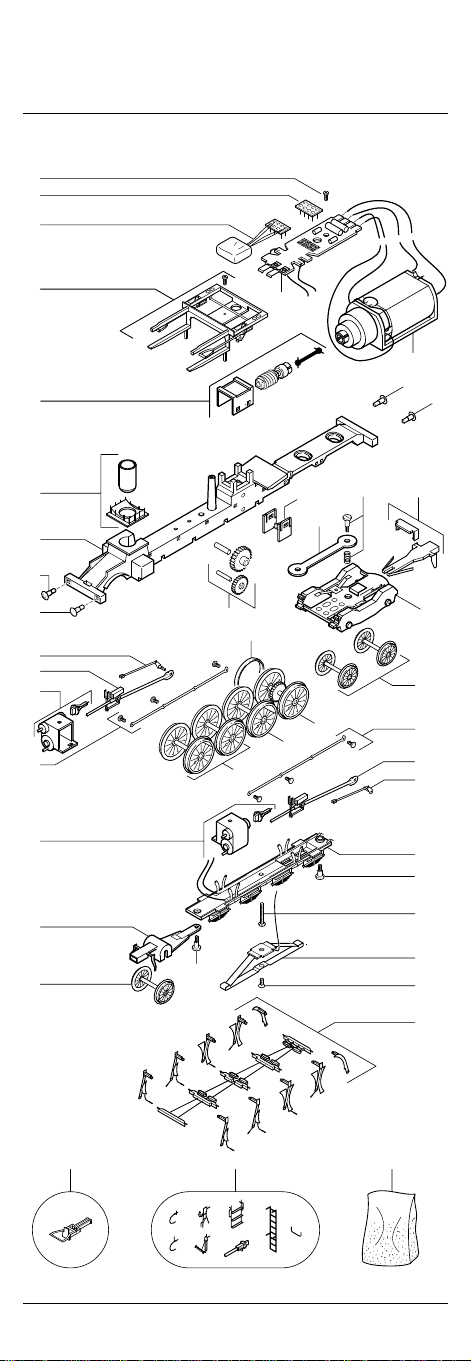
Ersatzteilliste Dampflokomotive BR 65
Spare Parts List locomotive BR 65
Gleichstrom / D.C.current
Wechselstrom / A.C.current
10
X
10
X
04
01
X
03
05
02
06
07
08
09
10
14
Page 15
Pos. Bestell Nr. Benennung
01 0612.99.01 Gehäuse komplett
02 0612.99.02 Ersatzteilbeutel Kleinteile Fahrerhaus und Tender
03 0612.99.03 Ersatzteilbeutel Kleinteile Vorbau
04 0610.99.04 Inneneinrichtung und Personal
05 0612.99.05 Umlauf rechts
06 0612.99.06 Umlauf links
07 0612.99.07 Wasserkasten links und rechts
08 0610.99.08 Windleitblech links und rechts
09 3268.99.00 Glühbirne
10 0610.99.10 Lampeneinsätze
X = Position X nicht im Ersatzteilbeutel enthalten
Bestellbeispiel:
Glühbirne mit Position 09 = 3268.99.00 Glühbirne
Pos. Order no. Description
01 0612.99.01 Complete housing
02 0612.99.02 Spare parts bag for small parts – Cab + tender
03 0612.99.03 Spare parts bag for small parts – Underframe
04 0610.99.04 Interior fittings + personnel
05 0612.99.05 Foot plate, right
06 0612.99.06 Foot plate, left
07 0612.99.07 Water tank, left + right
08 0610.99.08 Smoke-shield plate, left + right
09 3268.99.00 Bulb
10 0610.99.10 Lamp inserts
extension
X = Position X not contained in the spare parts bag
Order example:
Bulb with position 09 = 3268.99.00 Bulb
Wichtiger Hinweis!
Bei der Bestellung von Ersatzteilen muss die Bestell-Nr. und die Benennung angegeben werden. Ist dies nicht der Fall, kann die Bestellung nicht bearbeitet werden.
Important notice!
When ordering spare parts you must always state the order
number and give the description. If you do not do this, the order
cannot be processed.
15
Page 16
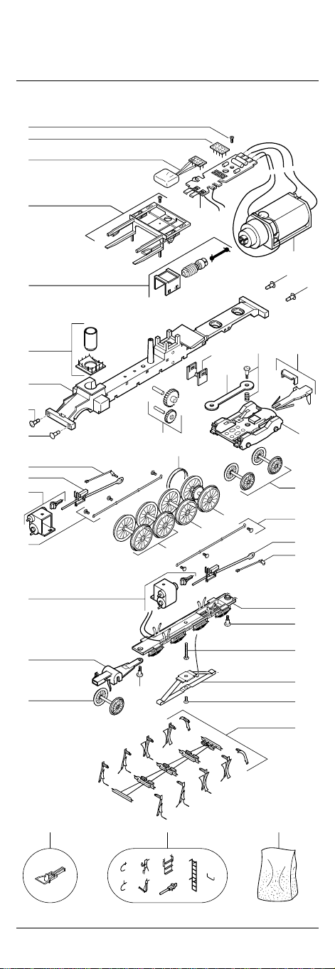
Ersatzteilliste Dampflokomotive BR 65
8
Gleichstrom / Wechselstrom
11
12
13
10
14
19
20
21
18
17
25
26
28
27
28
A
15
A
16
17
1
11
22
42
22
23
29
31
32
33
24
30
27
26
25
34
11
35
36
11
11
37
11
38
414039
16
Page 17
Pos. Bestell Nr. Benennung
11 0610.99.11 Schraubensatz
12 0530.99.34 Blindstecker
13 9957.10.20** Decoder AC
14 0610.99.14 Steuerungsträger Support
15 0610.99.15 Platine
16 0610.99.16 Motor mit Support und Gummilager
17 0610.99.17 Puffer gerade
18 0610.99.18 Puffer gewölbt
19 0610.99.19 Schnecke, Kardanwelle, Schneckenhalter
20 0610.99.20 Hülse für Raucheinsatz
21 0610.99.21 Fahrgestell
22 0610.99.22 Deichsel
23 0610.99.23 Zahnradsatz mit Achsen
24 0612.99.24 Drehgestell mit Begrenzer
25 0610.99.25 Gestänge links und rechts
26 0610.99.26 Gestänge links und rechts
27 0610.99.27 Kuppelstangen links und rechts mit Schrauben
28 0610.99.28 Zylinder links und rechts
29 0610.99.29 Haftreifen
30 0610.99.30* Radsatz Drehgestell – Gleichstrom
0611.99.30** Radsatz Drehgestell – Wechselstrom
31 0610.99.31* Radsatz mit Antriebsritzel und Haftreifen –
0611.99.31** Radsatz mit Antriebsritzel und Haftreifen –
32 0610.99.32* Radsatz mit großem Ausgleichsgewicht –
0611.99.32** Radsatz mit großem Ausgleichsgewicht –
33 0610.99.33* Radsatz mit kleinem Ausgleichsgewicht –
0611.99.33** Radsatz mit kleinem Ausgleichsgewicht –
34 0610.99.34 Abdeckung mit Radschleifer
35 0610.99.35 Vorlaufachse mit Feder
36 0610.99.36* Vorlaufrad – Gleichstrom
0611.99.36** Vorlaufrad – Wechselstrom
37 0611.99.37** Mittelschleifer – Wechselstrom
38 0612.99.38 Bremsbacken und Bremsgestänge
39 0550.01.39 Bügelkupplung
40 0610.99.40 Zurüstbeutel
41 0610.99.41 Zurüstbeutel mit Kohle
42 0612.99.42 Bremsansteuerung
* Bauteil wird nur bei Gleichstrom-Ausführung 0612 verwendet
** Bauteil wird nur bei Wechselstrom-Ausführung 0613 verwendet
Bestellbeispiel:
Platine mit Position 15 = 0610.99.15 Platine
Wichtiger Hinweis!
Bei der Bestellung von Ersatzteilen muss die Bestell-Nr. und die Benennung angegeben werden. Ist dies nicht der Fall, kann die Bestellung
nicht bearbeitet werden.
Abdeckung für Raucheinsatz
Normschacht Drehgestell
Normschacht-Abdeckung
Gleichstrom
Wechselstrom
Gleichstrom
Wechselstrom
Gleichstrom
Wechselstrom
- 2 x Bremsschlauch, links
- 2 x Bremsschlauch, rechts
- 2 x Heizschlauch
- 2 x Kupplungsimitat
- 2 x Kolbenstangenhülse
- 2 x Aufstiegsleiter hinten
- 2 x Aufstiegsleiter seitlich
- 4 x Griffstangen Pufferbohlen
17
Page 18
Spare Parts List locomotive BR 65
8
D.C.current / A.C.current
11
12
13
10
14
19
20
21
18
17
25
26
28
27
28
A
15
A
16
17
1
11
22
42
22
23
29
31
32
33
24
30
27
26
25
34
11
35
36
11
11
37
11
38
414039
18
Page 19
Pos. Order no. Description
11 0610.99.11 Set of screws
12 0530.99.34 Blind plug
13 9957.10.20** Decoder AC
14 0610.99.14 Control support
15 0610.99.15 Circuit board
16 0610.99.16 Engine with support and rubber bearing
17 0610.99.17 Straight buffer
18 0610.99.18 Curved buffer
19 0610.99.19 Auger, cardan shaft, auger holder
20 0610.99.20 Sleeve for smoke insert
21 0610.99.21 Chassis
22 0610.99.22 Draw-bar set
23 0610.99.23 Gearwheel set with axles
24 0612.99.24 Bogie with limiter
25 0610.99.25 Rods, left and right
26 0610.99.26 Rods, left and right
27 0610.99.27 Coupling rods, left and right, with screws
28 0610.99.28 Cylinder, left and right
29 0610.99.29 Traction tyres
30 0610.99.30* Wheelset bogie – direct current
0611.99.30** Wheelset bogie – alternating current
31 0610.99.31* Wheelset with driving pinion and traction tyres –
0611.99.31** Wheelset with driving pinion and traction tyres –
32 0610.99.32* Wheelset with large counterweight –
0611.99.32** Wheelset with large counterweight –
33 0610.99.33* Wheelset with small counterweight –
0611.99.33** Wheelset with small counterweight –
34 0610.99.34 Cover with wheel sliding contact
35 0610.99.35 Lead axle with spring
36 0610.99.36* Lead wheel – direct current
0611.99.36** Lead wheel – alternating current
37 0611.99.37** Middle sliding contact – alternating current
38 0612.99.38 Brake shoes and brake linkage
39 0550.01.39 Bow coupling
40 0610.99.40 Add-on bag
41 0610.99.41 Add-on bag with coal
42 0612.99.42 Brake linkage
* Part is only used for the DC version 0612
** Part only used for the AC version 0613
Order example:
Circuit board with position 15 = 0610.99.15 Circuit board
Important notice!
When ordering spare parts you must always state the order number and
give the description. If you do not do this, the order cannot be
processed.
Cover for smoke insert
Standard shaft bogie
Standard shaft cover
direct current
alternating current
direct current
alternating current
direct current
alternating current
- 2 x Air-brake hose, left
- 2 x Air-brake hose, right
- 2 x Heating hose
- 2 x Imitation coupling
- 2 x Piston rod sleeve
- 2 x Rear ladder
- 2 x Side ladder
- 4 x Handrail buffer beams
19
Page 20
Brawa Modellspielwarenfabrik GmbH + Co.
Uferstraße 26-28 · D-73630 Remshalden
Telefon 07151 - 97 93 50
Telefax 07151 - 7 46 62
http://www.brawa.de
20
0612.99.43 / 10 5 00 - WAN
 Loading...