

Page 1
Betriebsanleitung
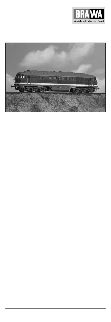
Diesellokomotive BR 232 – H0
Gleichstrom Artikel-Nr. 0310
Wechselstrom Artikel-Nr. 0311
In der dieselelektrischen Reisezuglokomotive 232 haben EisenbahnKonstrukteure aus der Sowjetunion und der ehemaligen DDR ihre
Schaffenskraft auf eindrucksvolle Weise vereint: Dieses Erlebnis
können Sie jetzt mit dem imposanten BRAWA-Modell der Baureihe
232 auf Ihrer Modellbahn-Anlage nachempfinden. Die EntwicklungsGeschichte dieser 2200 kW starken Diesellok beginnt mit der gründlichen Optimierung der russischen Vorstufen 130 und 131 im Auftrag der Deutschen Reichsbahn. Aufgabenstellung war die Bedarfsdeckung für den schweren Reisezugdienst auf den Hauptstrecken
der DR. Daher musste z.B. zwecks Einbau der elektrischen
Zugheizeinrichtung die Fahrzeuglänge auf LÜP = 20.820 mm vergrößert werden. Weitere Modifizierungen betrafen den Drehzahlregler des Dieselmotors, die Führerraumheizung, das Vorwärmgerät
sowie die Schaltung der elektropneumatischen Bremse. 1973 begann die erste Auslieferung der Baureihe 132, später in 232 umbenannt, von der sowjetischen Diesellokomotivfabrik „Oktoberrevolution“ in Woroschilowgrad mit anfangs 42 Fahrzeugen an die DR.
Am 22. Juli 1983 wurde die Beschaffung dieser ungemein einsatzbewährten, bis zu 140 km/h schnellen Baureihe mit der feierlichen
Lok-Übergabe an das Bw Reichenbach abgeschlossen. Mit dem
schweren Diesellokmodell der 232 von BRAWA haben Sie jetzt endlich die äußerst vorbildgerechte Gelegenheit, das Erneuerungsprogramm der DR auf Ihrem H0-Schienenverkehr perfekt zu
rekonstruieren.
1
Page 2

Diesel locomotive BR 232 – H0
Locomotive Diesel BR 232 – H0
Operating Instructions
Direct current model
Alternating current model
The diesel-electric passenger train locomotive 232 impressively
unites the creativity of railway designers from the Soviet Union
and the former German Democratic Republic. This experience you
can now relive on your model railroad with the imposing BRAWA
232 series model. The developmental history of these 2200 kW
strong diesel locomotives starts with the thorough optimization
of the Russian pre-stages 130 and 131 by order of the East German State Railways. The task was to satisfy the requirements of
the heavy passenger train service on the main lines of the East
German State Railways. For this reason it was e.g. necessary to
extend the vehicle length to LOB= 20.820 mm for the purpose of
installing the electric train heating facility. Further modifications
concerned the diesel engine’s speed governor, the driver’s cab
heating, the preheating device as well as the wiring of the
electropneumatic brake. In 1973, the first delivery of the 132
series, later renamed 232, by the Soviet diesel locomotive factory
„October Revolution“ in Woroschilowgrad to the East German
State Railways commenced with initially 42 vehicles.
On the 22nd of July 1983, the procurement of this up to 140 km/h
fast series which had proven immensely competent in the field,
was concluded with the ceremonial handing over of a locomotive
to the engine shed Reichenbach. With its exceptional
resemblence to the model, the BRAWA heavy diesel locomotive
model of the 232 now offers you the opportunity to perfectly
reconstruct the renewal programme of the East German State
Railways on your H0-model railroad.
Instructions de service
Modèle à courant continu
Modèle à courant alternativ
Les constructeurs des chemins de fer de l’Union soviétique et de
l’ancienne RDA ont conjugué leur énergie de création d’une façon
impressionnante dans les locomotives 232 électro-diesel des
trains de voyageurs : vous pouvez en constater le résultat sur le
modèle imposant BRAWA de la série 232 qui se trouve dans votre
installation miniature. L’histoire du développement de ces puissantes loco à moteur diesel de 2200 kW a commencé avec ‘optimisation systématique des modèles prédécesseurs russes 130 et
131, réalisés pour les Chemins de fer allemands. La mission était
de couvrir les besoins de l’important service de trains de voyageurs sur les lignes principales de la RDA. C’est ainsi que par ex.
En vue du montage du dispositif de chauffage électrique des
trains, il fallait que la longueur des véhicules soit augmentée à
LÜP = 20.820 mm. D’autres modifications concernèrent la régulation du régime du moteur diesel, le chauffage de la cabine du
conducteur, l’appareil de préchauffage ainsi que la commande du
frein électro-pneumatique. « Révolution d’Octobre », usine soviétique de fabrication de locomotives à moteur diesel se trouvant à
Woroschilowgrad, commença en 1973 par livrer à la RDA 42
premiers véhicules de la série 132 qui, plus tard, fut désignée par
232. Le 22 juillet 1983, l’approvisionnement de cette série d’une
2
Page 3
Locomotiva Diesel BR 232 – H0
vitesse allant jusqu’à 140 km/h, ayant fait ses preuves prodigieusement, se termina par la cérémonie de remise de loco à la Bw
Reichenbach. Ce lourd modèle de loco à moteur diesel de la série
232 de BRAWA vous donne enfin maintenant l’occasion extrêmement exemplaire de pouvoir reconstruire parfaitement le programme de renouveau de la RDA sur votre trafic ferroviaire H0.
Istruzioni sul funzionamento
Versione a corrente continua
Versione a corrente alternata
Nella locomotiva 232 per treni viaggiatori dieselelettrici, i
costruttori ferroviari dell’Unione Sovietica e della Germania
dell’Est hanno combinato la loro forza creativa realizzando una
locomotiva di grande effetto. Adesso potrete rivivere questa
esperienza sul vostro plastico con l’imponente modello della ditta
BRAWA della serie 232. La storia dello sviluppo di questa potente
locomotiva Diesel da 2200 kW, iniziò con l’ordine della Deutsche
Reichsbahn di ottimizzare radicalmente i modelli russi 130 e 131.
Il compito era di coprire il fabbisogno della DR nel servizio di
treni pesanti per viaggiatori sui tratti principali. Per esempio per
integrare l’impianto di riscaldamento elettrico si è dovuta
aumentare la lunghezza del veicolo – a lunghezza tra i respingenti
= 20.820 mm. Le altre modifiche hanno interessato il regolatore
di velocità del motore Diesel, il riscaldamento della cabina del
macchinista, l’apparecchio di preriscaldamento nonché l’integrazione del freno elettropneumatico. Nel 1973 iniziò la prima
fornitura alla DR con 42 veicoli della serie 132, più tardi
ribattezzata 232, da parte della fabbrica di locomotive Diesel
sovietica “Rivoluzione d’ottobre” a Woroschilowgrad. Il 22 luglio
1983 è stato concluso l’acquisto di questa serie estremamente
veloce 140 km/h, già comprovatissima, con la cerimoniosa
consegna della locomotiva alla Bw Reichenbach. Con il modello
di locomotiva Diesel pesante 232 della BRAWA avete finalmente
la possibilità di ricostruire perfettamente sul vostro plastico H0
il programma di rinnovo della Deutsche Reichsbahn.
3
Page 4

Inhaltsverzeichnis
Contents
Benennung Seite
Allgemeine Hinweise ..................................................................... 5
Entnahme der Lok aus der Verpackung ......................................... 6
Zusatzbauteile montieren............................................................... 6
Wartungsarbeiten
• 1. Ölen....................................................................................... 7
• 2. Umrüsten und Umprogrammieren auf Digitalbetrieb ............ 7
• 3. Gehäuse demontieren ....................................................... 8, 9
• 4. Platine tauschen ................................................................ 8, 9
• 5. Motor tauschen ................................................................. 8, 9
• 6. Digitaldecoder oder Umschaltrelais tauschen ................... 8, 9
• 7. Haftreifen und Radsätze tauschen ..................................... 8, 9
• 8. Kupplungsnormschacht tauschen ..................................... 8, 9
• 9. Schleifer tauschen bei Wechselstrom-Ausführung AC ...... 8, 9
Ersatzteilliste Gleichstrom-Ausführung DC ...................... 12, 14, 15
Ersatzteilliste Wechselstrom-Ausführung AC................... 13, 14, 15
Bestellbeispiel.............................................................................. 15
Description Page
General information ....................................................................... 5
Removing the locomotive from the packaging .............................. 6
Fitting additional parts ................................................................... 6
Maintenance works
• 1. Lubricating ............................................................................ 7
• 2. Conversion and reprogramming to digital operating ............. 7
• 3. Dismantling housing ..................................................... 10, 11
• 4. Exchanging the circuit board ......................................... 10, 11
• 5. Exchanging the engine .................................................. 10, 11
• 6. Exchanging the digital decoder or change-over relay .... 10, 11
• 7. Exchanging traction tires and wheelsets ....................... 10, 11
• 8. Exchanging coupler pocket ........................................... 10, 11
• 9. Exchanging the pick up, alternating current AC ............. 10, 11
Spare parts list direct current .......................................... 12, 14, 15
Spare parts list alternating current .................................. 13, 14, 15
Order example ............................................................................. 15
4
Page 5
Allgemeine Montage- und Sicherheitshinweise
• Diese Bedienungsanleitung beschreibt sämtliche Arbeitsvorgänge
die zur Wartung und Instandhaltung notwendig sind.
Bitte lesen Sie diese Bedienungsanleitung bevor Sie
mit den Arbeiten beginnen.
• Bei unsachgemäßem Umgang mit elektrischen Bauteilen können
diese zerstört werden. Für entsprechende Arbeiten
(z.B. Platinenwechsel) können Sie sich an Ihren Fachhändler
oder den Hersteller wenden.
• Bei den folgenden Wartungsarbeiten ist die jeweilige Demontage
beschrieben, der Zusammenbau ist in umgekehrter Reihenfolge
auszuführen.
• Die folgenden Wartungsarbeiten sind bei Gleich- und Wechselstrom-Ausführungen fast identisch. Im Ausnahmefall wird im
entsprechenden Textabschnitt Bezug genommen.
• Achten Sie beim Zerlegen der Lokomotive auf die Einbaulage der
entsprechenden Bauteile. Wird ein Bauteil falsch eingebaut
kann dieses zerstört werden oder es kommt zu Funktionsstörungen im Betrieb.
General assembly and safety information
• These operating instructions describe all work steps necessary
for maintenance and repair. Please read these operating
instructions carefully before you start with your work.
• In the case of incorrect handling of electrical components, they
may be destroyed. Please ask your specialist dealer to help with
the necessary work (e.g. changing circuit boards).
• In the case of maintenance work, the disassembly is described
below, to re-assemble the tractor reverse the work steps.
• The maintenance work described below is virtually identical for
direct current and alternating current models. If there are any
differences these will be pointed out specifically.
• When dismantling the engine make a note of the mounted
position of the individual parts. An incorrectly mounted part can
be destroyed or operation can be disrupted.
1
5
Page 6
Arbeiten vor der Inbetriebnahme
Work to be performed before starting up
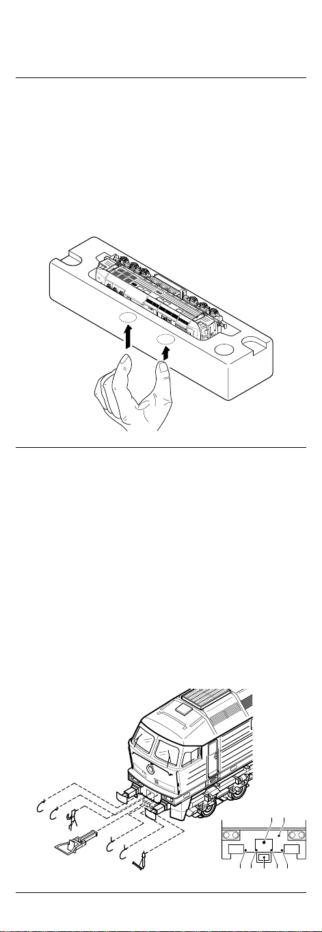
Entnahme der Lok aus der Verpackung (Fig. 1)
Verpackung öffnen, Styropor mit Lokomotive herausziehen.
Lokomotive über 2 Öffnungen an der Unterseite aus der Verpakkung drücken.
Removing the locomotive from the packaging
(Fig. 1)
Open the packaging, pull out polystyrene together with the
locomotive. Push locomotive from the packaging with the aid
of the two openings on the underside of the packaging.
Fig. 1
1
Zusatzbauteile montieren (Fig. 2)
In der Verpackung sind zusätzliche Bauteile lose beigelegt.
• 1 = 2 x Bügelkupplung
• Werden die Bauteile aus dem Zurüstbeutel für Vitrinenmodelle
montiert, ist die Lok nicht mehr für den Fahrbetrieb geeignet.
2 = 4 x Luftschlauch links 5 = 2 x Heizschlauch
3 = 4 x Luftschlauch rechts
4 = 2 x Kupplungsimitat
Fitting additional parts (Fig. 2)
Accessory parts have been loosely enclosed in the packaging.
• 1 = 2 x bow coupling
• If parts contained in the setting-up bag for showcase models are
fitted, the locomotive is no longer suitable for running on tracks.
2 = 4 x air hose right 5 = 2 x heating hose
3 = 4 x air hose left
4 = 2 x imitation coupling
Fig. 2
1
3
3
4
1
2
2
5
4
1
33
252
6
Page 7
Wartungsarbeiten
Maintenance works
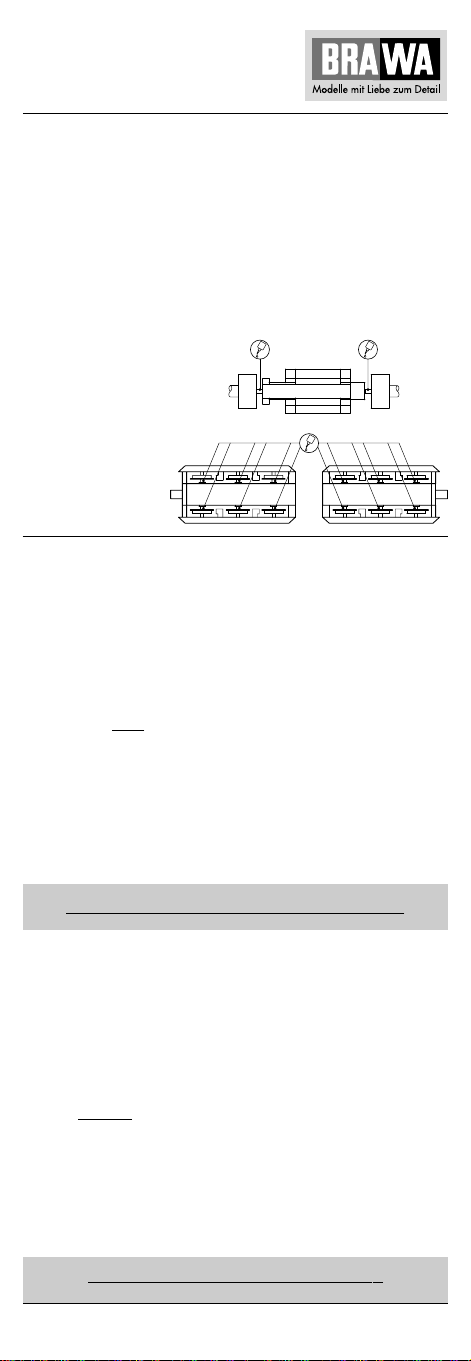
1. Ölen (Fig. 3)
Der Motor und die Lagerstellen der Radsätze können an den
gekennzeichneten Punkten sparsam mit Öl der Modellbaubranche
geölt werden. Zum Ölen des Motors ist das Gehäuse und die
Platine abzunehmen, siehe Seite 8 Punkt 3 und 4.
1. Lubricating (Fig. 3)
The engine and the wheelset bearings may be sparingly lubricated
at the marked places with oil used for model making purposes.
In order to lubricate the engine, remove the housing and the circuit
board, compare page 10, item 3 and 4.
Fig. 3
Motor
Engine
Räder
Wheels
Umrüsten auf Digitalbetrieb
Gleichstrom Ausführung 0310
Gehäuse abnehmen, Blindstecker (03) abziehen und Digital-Decoder (04) einstecken (siehe Seite 09).
Den richtigen Einbau des Digitaldecoders und dessen
Einsteckrichtung entnehmen Sie der Einbauvorschrift
des Decoderherstellers.
Nach Einstecken des Digitaldecoders ist die Funktion des Lichtes zu
prüfen. Wenn keine Lichtfunktion – Stecker um 180° drehen und
einstecken.
Wechselstrom-Ausführung 0311
Lokomotiven in Wechselstrom-Ausführung AC werden serienmäßig
mit Premium-Digitaldecoder (04) ausgeliefert. Der Decoder erkennt
die Betriebsart (analog / digital) selbstständig. Soll der Decoder
umprogramiert werden, liegt die Einbau- und Betriebsanleitung
Premium-Digitaldecoder bei.
Der Decoder ist Werkseitig auf Adresse 03 eingestellt.
Converting to digital operation
DC version 0310
Remove housing, pull off dummy connector (03) and insert digital
decoder (04), (see page 11).
Please consult the installation instructions issued by the decoder
manufacturer for correct installation of the digital decoder and
its insert direction.
After inserting the digital decoder, check that the light functions. If
the light does not work, turn the connector through 180°.
AC version 0311
The premium digital decoder (04) is standard for the alternating
current (AC) locomotives models. The decoder independently
identifies the operation type (analogue/digital). Please refer to the
enclosed installation and operation instructions “Premium Digital
Decoder” in the event that the decoder needs to be reprogrammed.
The decoder is set to address 03 in the factory.
7
Page 8

Wartungsarbeiten
3. Gehäuse demontieren (Fig. 5)
Puffer (1) an beiden Seiten der Lokomotive herausziehen, Gehäuse
(2) nach oben abnehmen.
4. Platine tauschen (Fig. 5)
Gehäuse abnehmen, siehe Punkt 3.
Blindstecker (3) bei Gleichstrom-Ausführung DC oder Digitaldecoder (4) bei Wechselstrom-Ausführung AC abziehen.
Befestigungsschrauben (5) herausdrehen. Sämtliche Kabel (6), von
der Platine (7) ablöten. Bitte kennzeichnen Sie sich wo die einzelnen
Kabel angelötet waren. Platine nach oben abnehmen.
5. Motor tauschen (Fig. 5)
Gehäuse abnehmen, siehe Punkt 3.
Tank (8) an der Unterseite abziehen (ist mit Klebeband fixiert).
Befestigungsschrauben (5) der Platine herausdrehen, Platine (7)
mit sämtlichen Kabeln zur Seite klappen. Gewichte (9) nach oben
abnehmen. Motorlagerungen (10) mit Schraubendreher nach oben
drücken, Motor (11) nach oben herausnehmen, Kabel (12) vom
Motor ablöten. Kardanwelle (13) und Motorlagerungen (10)
vom Motor entfernen.
Hinweis: Bei Wechselstrom-Ausführung wird nur das vordere
Drehgestell angetrieben, aus diesem Grund entfällt die hintere
Kardanwelle (13) wie in Fig. 5 dargestellt.
6. Digitaldecoder tauschen (Fig. 5)
Gehäuse abnehmen, siehe Punkt 3.
Digitaldecoder (4) abziehen und neuen einstecken.
7. Haftreifen und Radsätze tauschen (Fig. 5)
Achtung: Lokomotive umdrehen, Räder und Getriebeabdeckung
müssen nach oben zeigen.
Hinweis: Gleichstrom- und Wechselstrom-Ausführungen haben
unterschiedliche Drehgestelle. Bei der Gleichstrom-Ausführung DC
sind beide Drehgestelle gleich wie in Fig. 5 links (vorn) dargestellt.
Bei der Wechselstrom-Ausführung AC sind die Drehgestelle
unterschiedlich, da das hintere Drehgestell nicht angetrieben wird.
Wie in Fig. 5 links und rechts (vorn und hinten) dargestellt.
Je nach Ausführung der Lokomotive (DC / AC) kann sich die
Anzahl und Position der Haftreifen ändern.
Gleichstrom-, Wechselstrom-Ausführung DC:
Getriebeabdeckung (14) mit kleinem Schraubendreher anheben und
ausclipsen, Radsätze (15) entnehmen und Haftreifen (16) wechseln.
Wechselstrom-Ausführung AC:
Schrauben (17 und 18) herausdrehen, Schleifer (19) und Getriebeabdeckung (20) abnehmen, Radsätze (21) entnehmen.
8. Kupplungsnormschacht tauschen (Fig. 5)
Normschacht-Stecker (22) herausziehen, Kupplungsnormschacht
(23) mit Kupplung (24) entnehmen. Kupplung aus Kupplungsnormschacht herausziehen. Beim Zusammenbau ist darauf zu achten,
dass die Normschacht-Feder (25) richtig eingesetzt ist.
9. Schleifer tauschen bei Wechselstrom-
Ausführung AC (Fig. 5)
Befestigungsschraube (18) des Schleifers (19) herausdrehen,
Schleifer abnehmen.
8
Page 9
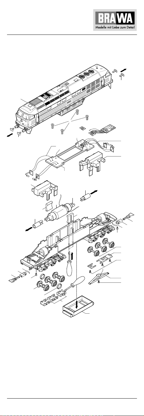
Fig. 5
4
vorn (1) hinten (2)
1
2
1
1
9
10
13
25
23
24
22
15
16
5
3 DC
6
7
13
11
12
10
Clip
14
4 AC
6
9
2
23
25
22
21
20
17
19
18
8
9
Page 10

Maintenance works
3. Dismantling housing (Fig. 5)
Pull out buffer (1) on both sides, remove housing (2) upwards.
4. Exchanging the circuit board (Fig. 5)
Remove housing, see item 3.
Pull off dummy plug (3) from the direct current DC model or digital
decoder (4) of the AC model. Unscrew mounting screws (5).
Unsolder all wires (6) from the circuit board. For your own benefit
please mark where the individual wires were connected.
Remove circuit board upwards.
5. Exchanging the engine (Fig. 5)
Remove housing, see item 3.
Pull tank (9) off the underside (fastened with adhesive tape).
Unscrew the circuit board mounting screws (5), fold the circuit
board (7) including all wires to the side. Remove weights (9)
upwards. Push engine bearings (10) upwards with a screwdriver,
remove engine (11) upwards, unsolder wires (12) from the engine.
Remove carden shaft (13) and engine bearings (10) from the
engine.
Note: In the AC model only the front truck is driven. For this reason,
there is no back cardan shaft (13) as shown in Fig. 5.
6. Exchanging the digital (Fig. 5)
Remove housing, see item 3.
Revove digital decoder (4) and plug in a new one.
7. Exchanging traction tires and wheelsets (Fig. 5)
Warning: Turn locomotive over, the wheels and gear covering must
be pointing upwards.
Note: Direct and alternating current models have different trucks.
In the DC model, both trucks are the same as shown in Fig. 5
(front). In the AC model the trucks are different because the back
truck is not driven as shown in Fig. 5 left and right (front and back).
Depending on the locomotive model (DC/AC), the number and
position of the traction tires may vary.
DC, AC model:
Lift the gear covering (14) with a small screw driver and unclip.
Remove wheelsets (15) and exchange traction tires (16).
AC model:
Unscrew screws (17 and 18) remove pick up (19) and gear
covering (20), remove wheelsets (21).
8. Exchanging coupler pocket (Fig. 5)
Pull out coupler pocket pin (22), remove coupler pocket (23) with
coupler (24). Pull out coupler from coupler pocket. Please ensure
when assembling that the coupler spring (25) is positioned
correctly.
9. Exchanging the pick up, alternating current AC
(Fig. 5)
Unscrew the pick up’s (19) mounting screws (18) and remove
pick up.
10
Page 11
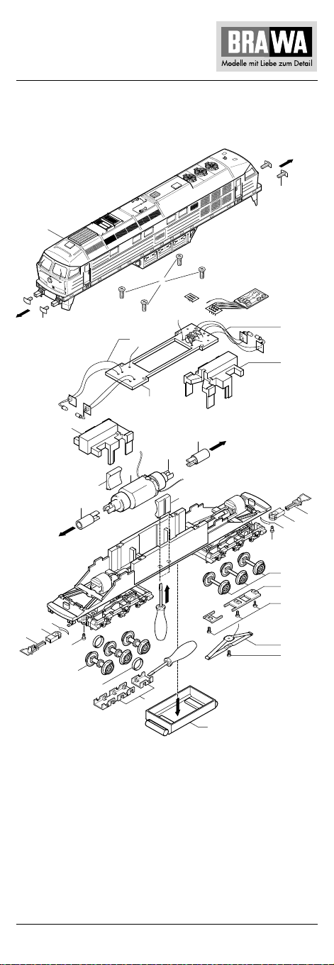
Fig. 5
4
front (1) back (2)
1
2
1
1
9
10
13
25
23
24
22
15
16
5
3 DC
6
7
13
11
12
10
Clip
14
4 AC
6
9
2
23
25
22
21
20
17
19
18
8
11
Page 12
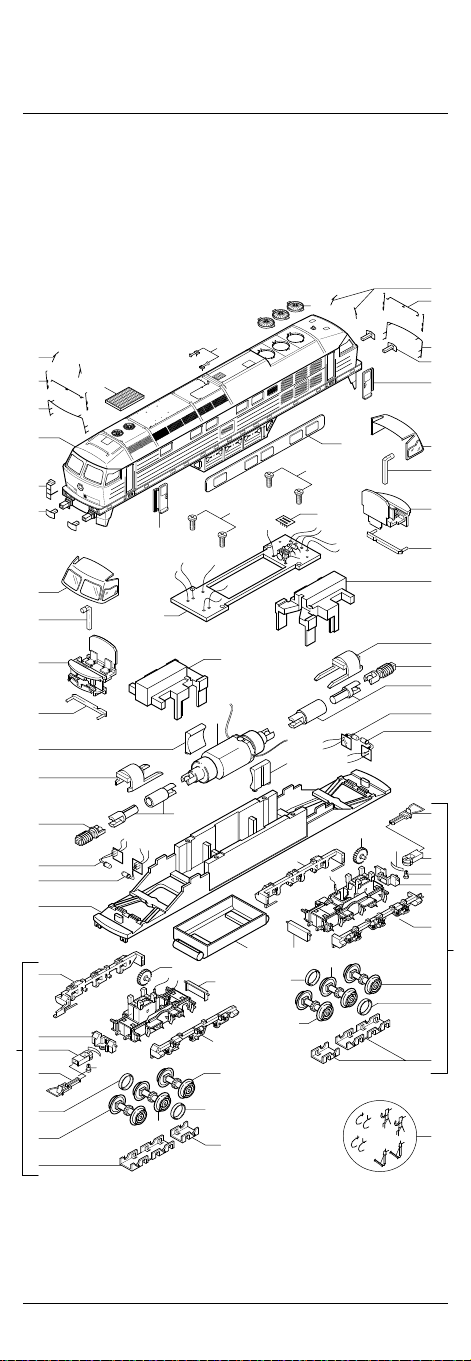
Ersatzteilliste Diesellokomotive BR 232
Spare Parts List Diesel locomotive BR 232
Gleichstrom / D.C.current
Ersatzteilliste siehe Seite 14 und 15.
Spare parts list see page 14 and 15.
vorn (1) hinten (2)
front (1) back (2)
26
23
21
23
21
51
31
22
20
32
38
34
38
46
45
08
24
25
44
33
33
17
05
02
29
1
37
01
18
27
40
41
41
43
03
04
48
47
33
33
09
42
46
48
33
33
11
14
09
51
20
35
32
38
34
38
43
45
08
04
25
24
02
19
17
18
33
33
05
09
14
16
14
09
16
14
11
16
30
12
Page 13
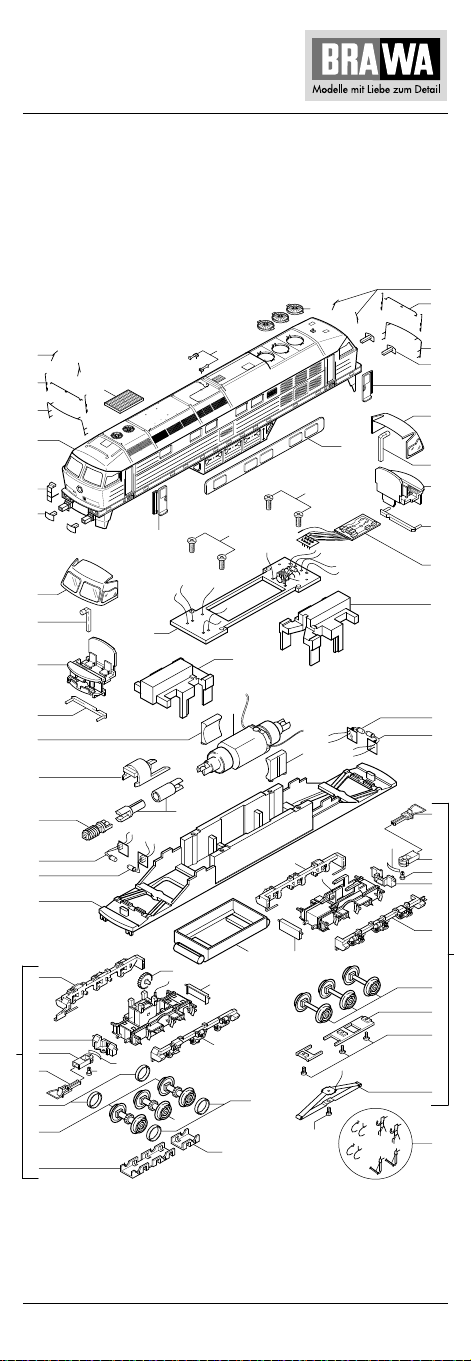
Wechselstrom / A.C.current
7
Ersatzteilliste siehe Seite 14 und 15.
Spare parts list see page 14 and 15.
vorn (1) hinten (2)
front (1) back (2)
26
23
21
23
21
51
31
22
20
32
38
34
38
46
45
08
24
25
44
33
33
17
06
02
14
12
16
29
1
37
01
19
18
27
40
41
41
43
03
46
04
33
33
48
10
47
33
33
14
50
16
51
20
35
32
38
34
38
36
43
03
25
24
02
19
17
18
33
33
0
13
49
50
15
30
13
Page 14

Ersatzteilliste Diesellokomotive BR 232
Spare Parts List Diesel locomotive BR 232
Pos. Bestell Nr. Benennung Description
Order no.
01 0410.50.01 Platine für AC/DC PCB for AC/DC
02 0550.01.39 Kupplungen (2 Stück) Coupler (2 pcs.)
03 0308.50.03 Motor Motor
04 0410.50.04 Kardanwelle kpl. Cardan shaft
05* 0304.50.05 Drehgestell Gleichstrom Truck complete DC
06** 0305.50.06 Drehgestell WechselstromTruck complete AC
07** 0305.50.07 Drehgestell WechselstromTruck complete AC
08 0410.50.08 Schnecke Worm gear
09* 0410.50.09 Radsatz Gleichstrom Wheel set DC with-
10** 0440.50.10 Radsatz Wechselstrom Wheel set AC with-
11* 0410.50.11 Radsatz Gleichstrom Wheel set DC
12** 0440.50.12 Radsatz Wechselstrom Wheel set AC
13** 0440.50.13 Radsatz Wechselstrom Wheel set AC with-
14 0410.50.14 Haftreifen Traction Tire
15** 0440.50.15 Wechselstrom Schleifer AC pick up
16 0304.50.16 Getriebeabdeckung Gear Box Cover
17 0304.50.17 Normschacht Coupler Pocket
18 0304.50.18 Normschacht Stecker Coupler Pocket Pin
19 0410.50.19 Normschacht Feder Coupler Spring
20 0304.50.20 Puffer eckig Buffer square
21 0308.50.21 Handgriffset Handrail set
22 0304.50.22 Leiter Stirnseite Front Ladder
23 0304.50.23 Scheibenwischer Wipers
24 0410.50.24 Glühbirne hell Clear Bulb
25 0410.50.25 Glühbirne rot Red Bulb
26 0308.50.26 Ventilator kpl. Fan complete
27 0308.50.27 Signalhorn Signal Horn
29 0308.50.29 Lüfterabdeckung Fan cover
30 0304.50.30 Zurüstteile Parts set
31 0310.50.31 Gehäuse kpl. Body complete
32 0410.50.32 Frontfenster Front Window
33 0304.50.33 Drehgestellrahmen Truck sideframe
34 0410.50.34 Führerstand kpl. Drivers cabin cpl.
35 0310.50.35 Türe rechts Door right
36** 9750.50.00 Premium- Premium
37 0310.50.37 Türe links Door left
38 0410.50.38 Lichtleiter-Satz Light Guide set
40 0410.50.40 Seitenfenster Window side
41 0410.50.41 Platinen Schraube Screw for PCB
(2-teilig) (2 pcs.)
mit Antrieb with gears
mit Schleifer with pick up
ohne Haftreifennut out Traction Tires
ohne Haftreifennut out Traction Tires
mit Haftreifennut preparet for
Traction Tires
mit Haftreifennut preparet for
Traction Tires
ohne Zahnrad out gear wheel
(2-teilig) (2 pcs.)
(3-teilig) (3 pcs.)
4 x Luftschlauch links 4 x air hose left
4 x Luftschlauch rechts 4 x air hose right
2 x Kupplungsimitat 2 x imitation coupl.
2 x Heizschlauch 2 x heating hose
(4-teilig) (4 pcs. Set)
Digitaldecoder- AC digital decoder AC
14
Page 15
42* 0530.99.34 Blindstecker Gleichstrom Blind Plug DC
43 0410.50.43 Gewicht Weight
44 0410.50.44 Rahmen Frame
45 0410.50.45 Drehgestellhalter Truck holder
46 0380.99.11 Motorlager Motor bearing
47 0304.50.47 Tank Tank
48 0410.50.48 Zahnrad Drehgestell Gear Wheel truck
49** 0304.50.49 Getriebeabdeckung AC Gear Box Cover
Wechselstrom, 2-teilig (2 pcs.)
50** 0410.50.50 Schraube Getriebeab- AC Screw
deckung Wechselstrom Gear Box Cover
51 0410.50.51 Handgriffset Handtail Set
(1-teilig) (1 pcs.)
* Bauteil wird nur bei Gleichstrom-Ausführung verwendet
** Bauteil wird nur bei Wechselstrom-Ausführung verwendet
* Part is only used for the DC version
** Part is only used for the AC version
Wichtiger Hinweis!
Bei der Bestellung von Ersatzteilen muss die Bestell-Nr. und die
Benennung angegeben werden.
Ist dies nicht der Fall, kann die Bestellung nicht bearbeitet werden.
Bestellbeispiel: 0308.50.03 Motor
Important notice!
When ordering spare parts you must always state the order
number and give the description.
If you do not do this, the order cannot be processed.
Order example: 0308.50.03 Motor
15
Page 16
Brawa Modellspielwarenfabrik GmbH & Co.
Uferstraße 26-28 · D-73630 Remshalden
Telefon 07151 - 97 93 50
Telefax 07151 - 7 46 62
www.brawa.de
16
0410.50.52 / 02 5 02 – WAN
 Loading...