

Page 1
Betriebsanleitung
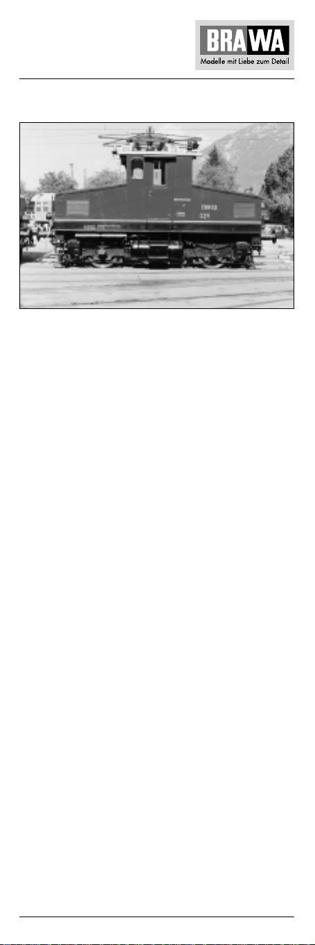
E-Lok E 69 03 – H0
Ausführung Gleichstrom 0220
Ausführung Wechselstrom 0221
Nach Beenden ihres langen Arbeitslebens ist die E 69 03 seit
1982 ein Prunkstück im Garmischer Lokschuppen. Ihre Stammstrecke, auf der sie 1913 ihren Dienst antrat, führte von Murnau
nach Oberammergau.
Die Strecke von Murnau nach Oberammergau der Lokalbahn AG
LAG war die erste mit einphasigem Wechselstrom (5000 V, Frequenz 16 Hertz) betriebene Eisenbahnstrecke Deutschlands. Der
Personenverkehr wurde mit Triebwagen abgewickelt, für den
Güterverkehr wurde eine Lokomotive, die LAG 1 verwendet. Aufgrund der guten Verkehrsabwicklung wurden 1909 und 1912
zusätzlich die LAG 2 bzw. LAG 3 in Dienst gestellt. Als 1938 die
Deutsche Reichsbahn die LAG übernahm, erhielten die beiden
Loks die Betriebsnummern E 69 02 und E 69 03.
Die E 69 03 wurde von Siemens und Kraus gebaut. Bei einem
Dienstgewicht von 24 t hatte die Lok zwei Motoren von je 126
kW Leistung. Wegen des enorm zunehmenden Verkehrs erhielt
die E 69 03 später stärkere Motoren von je 176 kW. Um Platz für
die entsprechende elektrische Ausrüstung zu erhalten und die
Lok zu versteifen, wurden zwischen dem Lokrahmen und den
Aufbauten ein Hilfsrahmen eingezogen. Bis 1953 befuhr sie ausschließlich ihre Stammstrecke, später kam sie auch in Rosenheim und Heidelberg zum Einsatz.
1
Page 2

Locomotive E 69 03 – H0
Operating Instructions
Direct current model 0220
Alternating current model 0221
At the end of its long working life, E 69 03 has been a showpiece
in the Garmisch engine shed. Its regular route where it started
service in 1913 was from Murnau to Oberammergau.
The line from Murnau to Oberammergau of the local railway AG
LAG was the first railway line in Germany to operate with single
phase AC current (5000 V at a frequency of 16 Hz). Passenger
traffic was handled by motor coaches, but a locomotive, LAG 1,
was responsible for goods traffic. Thanks to the positive traffic
development, locomotives LAG 2 and LAG 3 were also taken
into service in 1909 and 1912. In 1938 when the Deutsche
Reichsbahn took over LAG, the two locomotives were given the
operation numbers E 69 02 and E 69 03.
E 69 03 was built by Siemens and Krauss. With a service weight
of 24 tons, the locomotive had two motors with an output of
126 kW each. On account of the huge increase in traffic, E 69 03
later was fitted with stronger motors of 176 kW each. In order to
make space for the corresponding electric equipment and to
reinforce the locomotive, a supplementary frame was inserted
between the locomotive frame and the superstructure. Up until
1953, it operated just on its regular route, and was then later
also used in Rosenheim and Heidelberg.
Instructions de service
Modèle à courant continu 0220
Modèle à courant alternativ 0221
Après avoir terminé sa longue vie de travail, la motrice E 69 03
est une sensation dans le hangar des locomotives de Garmisch.
Sa ligne initiale depuis 1913 allait de Murnau à Oberammergau.
La ligne de Murnau à Oberammergau de Lokalbahn AG LAG fut
le premier tronçon d’Allemagne à courant alternatif (5000 V pour
une fréquence de 16 Hz). Le transport de personnes a été réalisé
par motrice, une locomotive LAG 1 a tété utilisée pour le trafic
marchandises. En raison du bon développement de transport, la
LAG 2 resp. la LAG 3 ont été mises en service en 1909 et en
1912. Lorsqu’en 1938, la Deutsche Reichsbahn a repris la LAG,
les numéros de service E 69 02 et E 69 03 ont été attribués aux
deux locomotives.
La E 69 03 a été construite par Siemens et Krauss. Pour un poids
de service de 24 t, la locomotive était équipée de deux moteurs
d’une puissance de 126 kW. C’est en raison du trafic accru que
la E 69 03 a été pourvue ultérieurement de moteurs plus puissants
de 174 kW chacun. Afin de gagner de la place pour l’équipement
électrique correspondant et de raidir la locomotive, un châssis
auxiliaire a été monté entre le châssis de la locomotive et la
superstructure. Jusqu’en 1953, la motrice a uniquement
fréquenté sa ligne initiale ; plus tard, elle a également été mise
en service à Rosenheim et à Heidelberg.
2
Page 3

Locomotiva E 69 03 – H0
Istruzioni sul funzionamento
Versione a corrente continua 0220
Versione a corrente alternata 0221
Dopo la sua lunga vita di duro lavoro, la E 69 03, dal 1982 è un
pezzo di lusso nella rimessa delle locomotive. Il tipico tratto su
cui entro in servizio nel 1913 andava da Murnau a Oberammergau.
Il tratto da Murnau a Oberammergau delle Lokalbahn AG LAG
(ferrovie locali) è stato il primo tratto ferroviario in Germania ad
impiegare corrente alternata ad una fase (5000 V con una
frequenza di 16 Hertz). Il trasporto passeggeri era affidato ad
una automotrice e il trasporto merci a una locomotiva, la LAG 1.
Visto il buono sviluppo della situazione del traffico nel 1909
e nel 1912 sono entrate in servizio rispettivamente la LAG 2 e
LAG 3. Quando nel 1938, le ferrovie del Reich si impossessarono
delle LAG, le due locomotive vennero ribattezzate E 69 02 e
E 69 03.
La E 69 03 veniva costruita dalla Siemens e dalla Krauss. Con un
peso di servizio di 24 t le due locomotive erano dotate di due
motori, ciascuno con 126 kW di potenza. Visto l’enorme aumento
del traffico, la E 69 03 più tardi venne equipaggiata con motori
ancora più potenti, da 176 kW ciascuno. Per creare uno spazio
sufficiente all’equipaggiamento elettrico e per irrigidire la
locomotiva, tra il telaio della locomotiva e la sovrastruttura si è
integrato un telaio ausiliario. Fino al 1953 viaggiava solo sul suo
tratto originario, più tardi entrò in servizio anche a Rosenheim e
a Heidelberg.
3
Page 4

Inhaltsverzeichnis
Contents
Benennung Seite
Allgemeine Hinweise .............................................................. 5
Entnahme der Lok aus der Verpackung .................................. 6
Zusatzbauteile montieren........................................................ 6
Wartungsarbeiten
• 1. Ölen................................................................................ 7
• 2. Umschalten von Unter- auf Oberleitung ......................... 7
• 3. Gehäuse demontieren ................................................ 8, 9
• 4. Motor tauschen .......................................................... 8, 9
• 5. Platine tauschen......................................................... 8, 9
• 6. Glühbirnenwechsel..................................................... 8, 9
• 7. Digitaldecoder tauschen............................................. 8, 9
• 8. Schleifer tauschen bei Wechselstrom-Ausführung..... 8, 9
• 9. Wartungsarbeiten an Radsätzen, Getriebe
und Kupplungsnormschacht ...................................... 8, 9
• 10. Pantograph tauschen ............................................... 8, 9
• 11. Umrüsten auf Digitalbetrieb ..................... 12, 13, 14, 15
Ersatzteilliste
Gleichstrom- und Wechselstrom-Ausführung .......... 20, 21, 22
Bestellbeispiel....................................................................... 22
Description Page
General information................................................................ 5
Removing the locomotive from the packaging ....................... 6
Fitting additional parts ............................................................ 6
Maintenance works
• 1. Lubricating ..................................................................... 7
• 2. Switch from cat wire to sub-line .................................... 7
• 3. Dismantling the housing ........................................ 10, 11
• 4. Exchanging the motor ............................................ 10, 11
• 5. Exchanging the circuit board.................................. 10, 11
• 6. Exchanging the bulb............................................... 10, 11
• 7. Exchanging the digital decoder .............................. 10, 11
• 8. Exchanging the sliding contact of the Alternating
• 7. Current Version ...................................................... 10, 11
• 9. Maintenance work on wheel sets, gearing
• 7. and standard coupling shaft................................... 10, 11
• 10. Exchanging the pantograph.................................. 10, 11
• 11. Converting for digital operation................ 16, 17, 18, 19
Spare parts list
direct current and alternating current ....................... 20, 21, 22
Order example ...................................................................... 22
4
Page 5

Allgemeine Montage- und Sicherheitshinweise
• Diese Bedienungsanleitung beschreibt sämtliche
Arbeitsvorgänge die zur Wartung und Instandhaltung
notwendig sind. Bitte lesen Sie diese Bedienungsanleitung
bevor Sie mit den Arbeiten beginnen.
• Bei unsachgemäßem Umgang mit elektrischen Bauteilen
können diese zerstört werden. Für entsprechende Arbeiten
(z.B. Platinenwechsel) können Sie sich an Ihren Fachhändler
oder den Hersteller wenden.
• Bei den folgenden Wartungsarbeiten ist die jeweilige
Demontage beschrieben, der Zusammenbau ist in
umgekehrter Reihenfolge auszuführen.
• Die folgenden Wartungsarbeiten sind bei Gleich- und
Wechselstrom-Ausführungen fast identisch.
Im Ausnahmefall wird im entsprechenden Textabschnitt
Bezug genommen.
General assembly and safety information
• These operating instructions describe all work steps
necessary for maintenance and repair. Please read these
operating instructions carefully before you start with your
work.
• In the case of incorrect handling of electrical components,
they may be destroyed. Please ask your specialist dealer to
help with the necessary work (e.g. changing circuit boards).
• In the case of maintenance work, the disassembly is
described below, to re-assemble the tractor reverse the work
steps.
• The maintenance work described below is virtually identical
for direct current and alternating current models. If there are
any differences these will be pointed out specifically.
5
Page 6
Arbeiten vor der Inbetriebnahme
Work to be performed before starting up
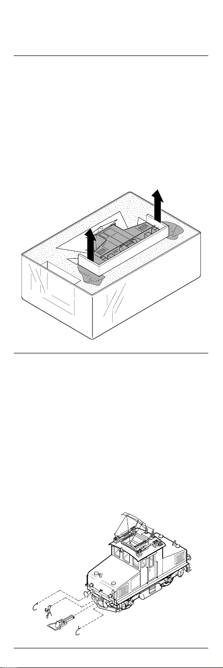
Entnahme der Lok aus der Verpackung (Fig. 1)
Deckel der Verpackung öffnen.
Schaumstoff an den Transportsicherungen (1) nach unten
drücken, Transportsicherungen mit der Lokomotive aus der
Verpackung ziehen.
Removing the engine from the packaging (Fig. 1)
Open the lid of the packaging.
Press the foam down using the tabs (1) securing the engine
during transport, then pull the engine out with these tabs.
Fig. 1
1
1
Zusatzbauteile montieren (Fig. 2)
In der Verpackung sind zusätzliche Bauteile lose beigelegt.
1 = 2 x Bügelkupplung
Werden die Bauteile aus dem Zurüstbeutel für Vitrinenmodelle
montiert, ist die Lok nicht mehr für den Fahrbetrieb geeignet.
2 = 2 x Luftschlauch links
3 = 2 x Luftschlauch rechts
4 = 2 x Kupplungsimitat
Fitting additional parts (Fig. 2)
Accessory parts have been loosely enclosed in the packaging.
1 = 2 x Coupling
If parts contained in the setting-up bag for showcase models
are fitted, the locomotive is no longer suitable for running on
tracks.
2 = 2 x air hose right
3 = 2 x air hose left
4 = 2 x imitation coupling
Fig. 2
3
4
1
2
6
Page 7
Wartungsarbeiten
Maintenance works
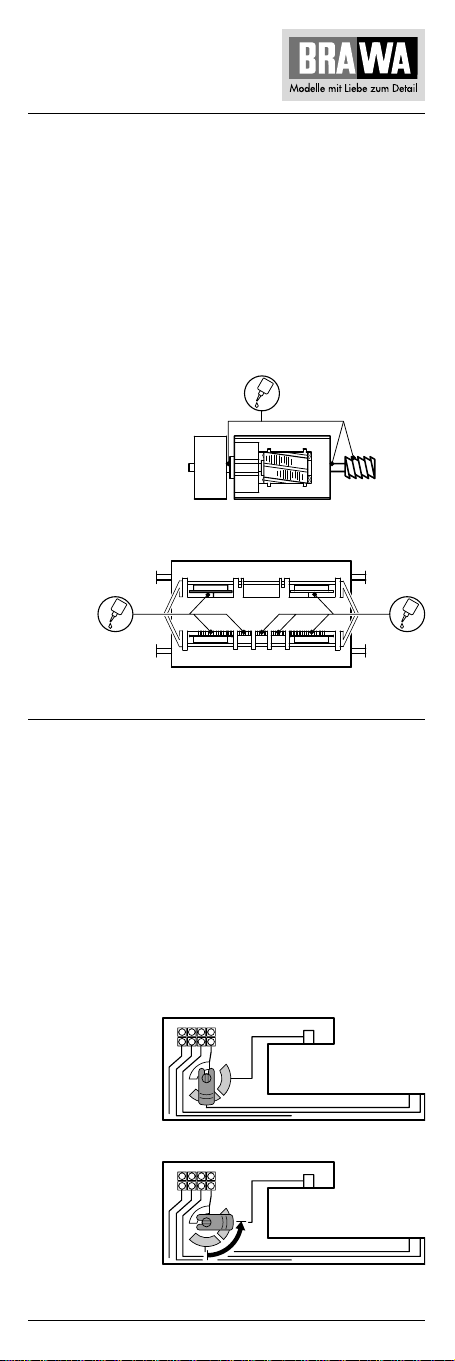
1. Ölen (Fig. 3)
Der Motor und die Lagerstellen der Radsätze können an den
gekennzeichneten Punkten sparsam mit Öl der Modellbaubranche geölt werden. Zum Ölen des Motors ist das Gehäuse
und die Getriebeabdeckung abzunehmen, siehe Seite 8 Punkt 3
und 4.
1. Lubricating (Fig. 3)
The motor and the wheelset bearings may be sparingly
lubricated at the marked places with oil used for model making
purposes. In order to lubricate the motor, remove the housing
and the gearbox cover, compare page 10, item 3 and 4.
Fig. 3
Motor
Motor
Räder
Wheels
2. Umschalten von Unter- auf Oberleitung (Fig. 4)
Die E-Lok wird für Unterleitungsbetrieb geliefert.
Für Oberleitungsbetrieb muß der Schalter (auf der Platine)
nach Abnehmen des Gehäuses (siehe Seite 8 Punkt 3) um 90°
gedreht werden.
2. Switching from subline to cat wire (Fig. 4)
The Engine is delivered for subline operation.
For cat wire operation, the switch (on the circuit board)
must be turned by 90 degrees after taking off body (compare
page 10, item 3).
Fig. 4
Unterleitung
Subline
Oberleitung
Cat wire
7
Page 8

Wartungsarbeiten
3. Gehäuse demontieren (Fig. 5)
2 Schrauben (1) an der Gehäuseunterseite herausdrehen
und Gehäuse (2) nach oben abnehmen.
4. Motor tauschen (Fig. 5)
Gehäuse abnehmen, siehe Punkt 3.
Befestigungsschrauben (3) herausdrehen, Getriebeabdeckung
(4) nach oben abnehmen. Kontaktbleche (5) vom Motor
abziehen. Motor (6) herausnehmen.
Hinweis:
Beim Ausbau des Motors muss auf die Einbaulage geachtet
werden – sonst falsche Fahrtrichtung.
5. Platine tauschen (Fig. 5)
Gehäuse abnehmen, siehe Punkt 3.
Rahmen (7) abnehmen, Blindstecker (8) bei DC-Ausführung
oder Digitaldecoder (9) bei AC-Ausführung abziehen.
Befestigungsschraube (10) herausdrehen, Platine (11) nach
oben abnehmen. Kabel (24) an der Platine ablöten, X nur bei
Wechselstrom AC.
Hinweis:
Die Kontaktbleche (12) der Platine müssen beim Einbau
auf den Radsätzen aufliegen.
6. Glühbirnenwechsel (Fig. 5)
Gehäuse abnehmen, siehe Punkt 3.
Glühbirne (13) an der Oberseite der Platine ablöten,
neue Glühbirne entsprechend anlöten.
7. Digitaldecoder tauschen (Fig. 5)
Gehäuse abnehmen, siehe Punkt 3.
Digitaldecoder (9) abziehen und neuen Digitaldecoder
einstecken.
8. Schleifer tauschen bei Wechselstrom-
Ausführung 0221 (Fig. 5)
Befestigungsschraube (14) des Schleifers (15) herausdrehen,
Schleifer abnehmen.
9. Wartungsarbeiten an Radsätzen, Getriebe
und Kupplungsnormschacht (Fig. 5)
Lokomotive umdrehen, Räder und Getriebeplatte müssen nach
oben zeigen. Schrauben (14 und 16) herausdrehen, Getriebeplatte (17) abnehmen. Radsätze (18) und Zahnräder (19) entnehmen. Kupplungsnormschacht (20) entnehmen.
Schneckenrad (21) ausbauen:
Gehäuse und Motor demontieren, siehe Punkt 3 und 4.
Das Schneckenrad (21) kann von oben entnommen werden.
10. Pantograph tauschen (Fig. 5)
Gehäuse abnehmen, siehe Punkt 3.
Schraube (22) im Gehäuseinneren herausdrehen und Pantograph (23) abnehmen.
8
Page 9
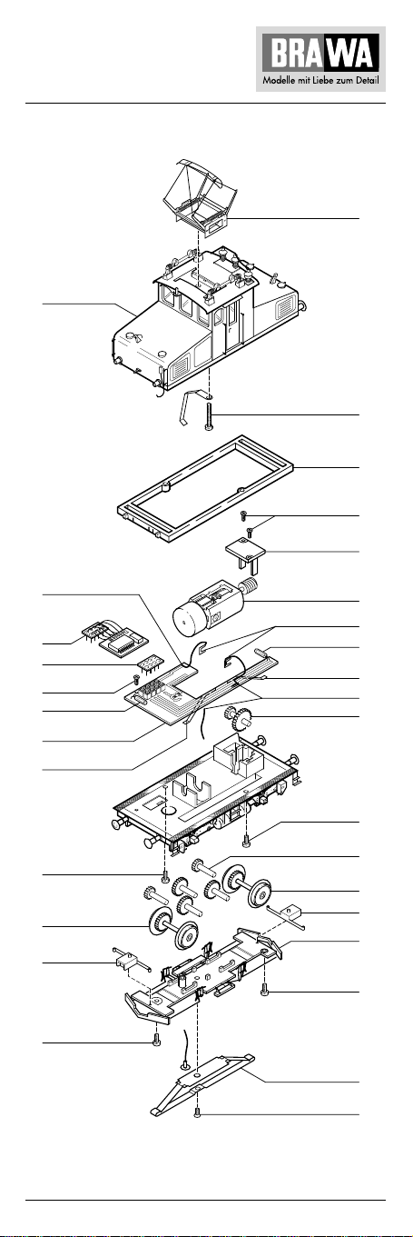
Fig. 5
02
23
22
07
03
04
24
09
08
10
13
11
12
01
18
20
16
AC
06
05
13
12
24
AC
21
X
01
19
18
20
17
16
X
15
14
9
Page 10

Maintenance works
3. Dismantle housing (fig. 5)
Unscrew 2 screws (1) on the bottom of the housing and lift
housing (2) off.
4. Replace motor (fig. 5)
Remove housing, see point 3.
Unscrew fastening screws (3), lift off gear cover (4). Remove
contact plates (5) from motor. Remove motor (6).
Note:
When removing the motor, pay attention to the installation
position, otherwise wrong direction of travel.
5. Replace the printed circuit board (fig. 5)
Remove housing, see point 3.
Remove frame (7), pull off dummy connector (8) for DC
version or digital decoder (9) for AC version. Unscrew
fastening screw (10), lift off printed circuit board (11),
unsolder cable (24) on the top of the printed circuit board.
Note:
The contact plates (12) of the printed circuit board must lie on
the wheelsets during assembly.
6. Replace the light bulbs (fig. 5)
Remove housing, see point 3.
Unsolder light bulb (13) from the upper side of the printed
circuit board, solder on new light bulb accordingly.
7. Replacing the digital decoder (fig. 5)
Remove housing, see point 3.
Pull off digital decoder (9) and insert new digital decoder.
8. Replace the trailer for AC version 0221 (fig. 5)
Unscrew fastening screw (14) of trailer (15), take off trailer.
9. Maintenance work on wheelsets, gear
and coupling norm shaft (fig. 5)
Turn the locomotive over so that the wheels and gear plate
point upwards. Unscrew the screws (14 and 16), remove gear
plate (17), remove wheelsets (18) and gear wheels (19).
Remove coupling norm shaft.
Remove worm wheel:
Dismantle housing and motor, see points 3 and 4.
The worm wheel (21) can be lifted out.
10. Change the pantograph (fig. 5)
Remove housing, see point 3.
Unscrew the screw (22) inside the housing and remove
pantograph (23).
10
Page 11
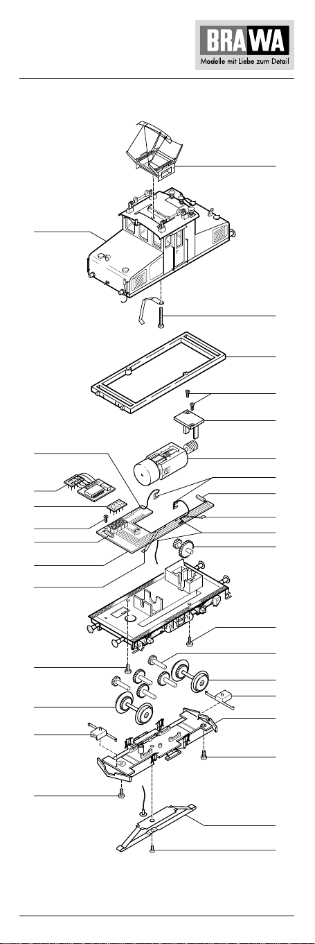
Fig. 5
02
23
22
07
03
04
24
09
08
10
13
11
12
01
18
20
16
AC
06
05
13
12
24
AC
21
X
01
19
18
20
17
16
X
15
14
11
Page 12

Wartungsarbeiten
11. Umrüsten und Umprogrammieren
auf Digitalbetrieb mit Uhlenbrock
Ausführung Gleichstrom 0220
Gehäuse (2) abnehmen, Blindstecker (8) abziehen und Digitaldecoder (9) einstecken (siehe Seite 8, 9).
Den richtigen Einbau des Digitaldecoders und dessen
Einsteckrichtung entnehmen Sie der Einbauvorschrift
des Decoderherstellers.
Nach Einstecken des Digitaldecoders ist die Funktion des Lichtes
zu prüfen. Wenn
und einstecken.
Ausführung Wechselstrom 0221
Diese Lok wird mit einem Digitaldecoder DGL 750 der
Fa. Uhlenbrock ausgeliefert. Deshalb muss die Lok nicht
umgerüstet, sondern nur umprogrammiert werden.
Im Auslieferungszustand ist der Decoder für den Analogbetrieb
programmiert.
Umprogrammieren von Analog- auf Digitalbetrieb
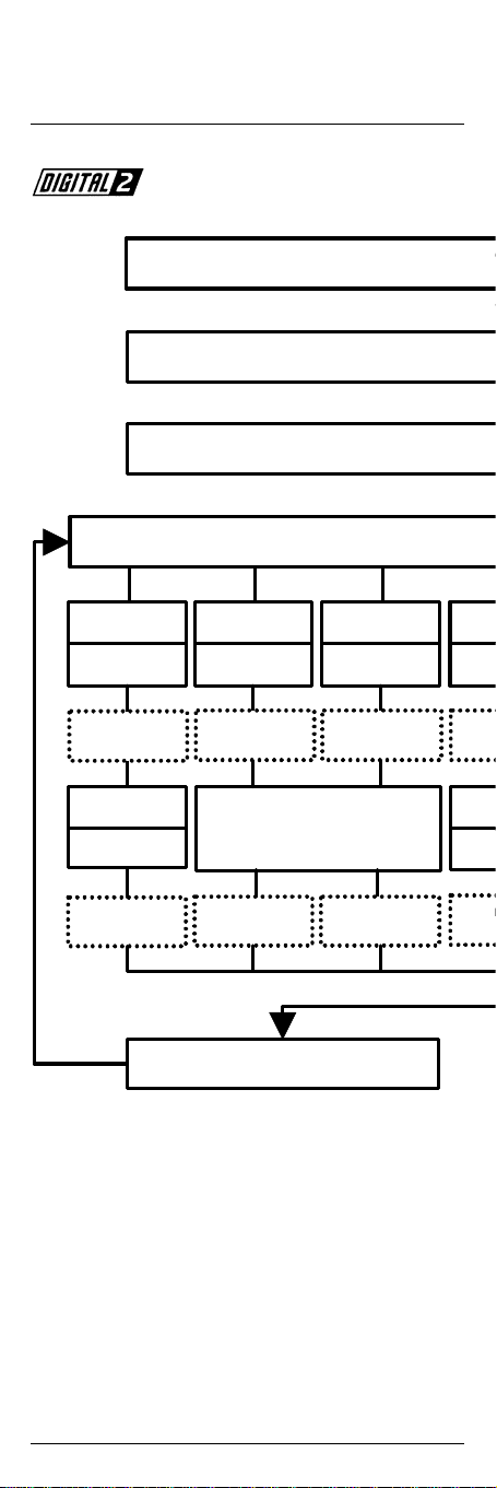
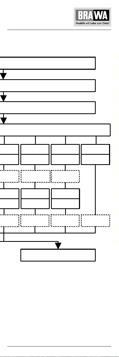
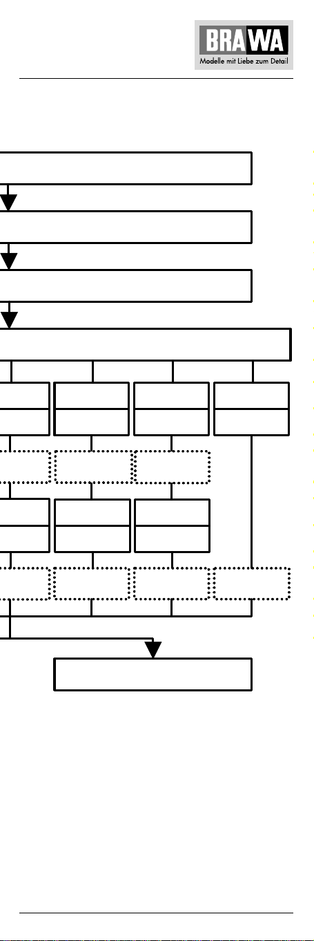
Eine Umprogrammierung muss anhand des Ablaufplanes
(siehe Seite 14/15) durchgeführt werden.
Hinweis:
Reagiert die Lok nach einem Programmiervorgang nicht mehr,
so ist wahrscheinlich die Lokadresse umprogrammiert worden.
Fehlerhafte Eingaben können korrigiert werden, indem Sie die
Werte mit der Funktion 10 (Reset) auf die Grundeinstellung
Digital, d.h. Lokadresse 01, Anfahren und Bremsen 01,
zurücksetzen.
keine Lichtfunktion – Stecker um 180° drehen
Eigenschaften
Lokdecoder mit zwei fahrtrichtungsabhängigen Funktionsausgängen für Gleichstrommotoren im Märklin-Motorola-Format.
• Programmierbar über Intellibox oder Control 80
• Zusammen mit der Intellibox sind 255 Adressen, mit anderen
Digitalgeräten 80 Adressen ansprechbar
• Pro Decoder 2 verschiedene Adressen möglich
• Lokadressen, Mindestfahrspannung, Beschleunigung,
Höchstgeschwindigkeit und Verzögerung können nach eigenen
Vorstellungen eingegeben werden
• Alle Werte bleiben dauerhaft gespeichert
• Voreingestellt auf die Adresse 01 und Digitalbetrieb
Digitalbetrieb
Im Digitalbetrieb fährt die Lok mit den von Ihnen eingegebenen
Parametern. Diese sind genauso wie Fahrtrichtung und Geschwindigkeit dauerhaft gespeichert. Das bedeutet, dass eine Lok
nach Wiedereinschalten der Anlage mit der letzten eingestellten
Geschwindigkeit weiterfährt. Damit kann die Lok auch im Blocksystem eingesetzt werden. Fährt die Lok im Digitalbetrieb auf
einen analogen Abschnitt, so behält Sie, solange eine ausreichende Spannung vorhanden ist, die digital eingestellte Geschwindigkeit bei. Ein Umschalten der Fahrtrichtung und die Erhöhung der
Fahrgeschwindigkeit sind in analogen Abschnitten nicht möglich.
Analogbetrieb
Im Analogbetrieb verhält sich der Decoder wie ein Fahrtrichtungsumschalter. Auf einem Digitalabschnitt bleibt die Lok stehen.
Auswahl der Betriebsart
Es gibt verschiedene Methoden, um zwischen der digitalen und
der analogen Betriebsart des Decoders zu wechseln. Stellen Sie
die Lok mit dem Digitaldecoder auf ein analoges Gleis und
12
Page 13

bringen Sie den Fahrtregler des Trafos in die Umschaltposition.
Nach kurzer Zeit schaltet der Decoder in den jeweils anderen
Betriebsmodus: von digital auf analog nach 4 Sekunden, von
analog auf digital nach 8 Sekunden.
Das Fahrzeug meldet die erfolgte Umschaltung mit blinken der
hinteren Beleuchtung. Alternativ kann der Decoder über die
Funktion 08 auf Analog (Wert = 01) oder Digital (Wert = 02)
programmiert werden. (Der Decoder kann auch im analogen
Betriebsmodus programmiert werden, weil er die Digitalspannung auf dem Gleis erkennt.)
Hinweis:
Der Zustand der Fahrzeugbeleuchtung, der im Digitalbetrieb
eingestellt wurde, bleibt im Analogbetrieb erhalten. Das heißt,
wurden im Digitalbetrieb die Fahrlichter ausgeschaltet, so
leuchten sie auch im Analogbetrieb nicht.
Kompatibilität
Der Baustein ist kompatibel mit der Anfahr-Bremsschaltung
für den C90 von Märklin.
Technische Daten
Adressen: 1-255, alle erreichbar über die Intellibox
Max. Motorstrom: 700 mA, wenn der Baustein lose in die
Motoranlaufstrom: kurzzeitig bis 2 A
Funktionsausgänge: je 900 mA
Größe: 19 x 16 x 5 mm
1-80, wenn mit einer anderen Zentrale
gefahren wird
Lok gelegt oder mit einem Klebepad
befestigt wird;
1 A, wenn der Baustein mit Heiß- oder
Wärmeleitkleber auf das Chassis geklebt
wird
Programmierung über die Intellibox
Die komfortabelste Art Uhlenbrock Decoder zu programmieren
bietet Ihnen die Intellibox. Im Programmiermodus erfolgt die
menügesteuerte Benutzerführung im Klartext. Die genaue Vorgehensweise bei der Programmierung wird im Intellibox-Handbuch
im Kapitel 9 beschrieben.
Programmierung über Loktool
Mit unserem Programm „Loktool“ für Windows können Sie mit
einem PC ab 386-25MHz mit angeschlossenem Interface 6050/
6051 unter Windows 3.x, 95 oder NT die Decoder sehr komfortabel programmieren.
Programmierung über die Märklin-Zentrale
Schließen Sie Ihr Control 80/80f mit Central-Unit (6035/6036 +
6020) oder die Control-Unit (6021) an ein Gleisstück an, auf dem
nur die zu programmierende Lok steht.
Zur Programmierung des Bausteins gehen Sie unbedingt in
der rechts beschriebenen Reihenfolge vor. Betätigen Sie keine
weiteren Tasten.
Reagiert die Lok nach einem Programmiervorgang nicht mehr,
so ist wahrscheinlich die Lokadresse umprogrammiert worden.
Entweder Sie probieren nacheinander alle Adressen aus, um zu
sehen, auf welche Ihr Fahrzeug jetzt reagiert oder Sie benutzen
die Suchfunktion der Intellibox oder des Lok-Tool-Pr ogramms
(siehe letzte Seite). Fehlerhafte Eingaben können korrigiert
werden, indem Sie die Werte mit der Funktion 10 auf den Auslieferzustand, d.h. Lokadresse 01, Anfahren und Bremsen 01,
zurücksetzen.
13
Page 14
Am Fahrregler gewünschte
Geschwindigkeit einstellen.
Die Lok fährt. Funktionstaste und
danach die Off-Taste betätigen
Lokadresse V min V max Besc
Trafo für 10 S ekunden aussc
Es sind keine störenden Digita
Lokadre
Bei jedem neuen
Weitere Funktionen programmieren
Fahrtrichtungsumschal
Die Lok ist jetzt im Programmiermodus. Zur Bestä
01 eingeben
Umschalter
01-80 eingeben
Umschalter
Loklampe blinkt
4mal langsam
02 eingeben
Umschalter
03 eingeben
Umschalter
Loklampe blinkt
4mal langsam
Loklampe blink t
4mal schnell
Loklampe blinkt
4mal langsam
06 e
Um
01-79
Um
Loklam
4ma
Loklampe blinkt
4mal schnell
Loklampe blinkt
4mal schnell
Lokla
4ma
Die zu programmie
Programmierung von Uhlenbrock-Decodern
Decoder-Handbuch
Eine umfassende technische Information zu unseren Digitaldecodern, einschließlich erweiterter Programmieranleitung
(Geschwindigkeitskennlinien, Belegung der Funktionstasten,
3. Lokadresse), ist im Fachhandel erhältlich.
14
Page 15
c
halten, dann wieder einschalten
linformationen mehr auf dem Gleis
sse wählen
Decoder ist das di e 01
lttaste 8 Sekunden drücken
tigung blinkt eine Lampe an der Lok 4mal langsam auf
rende Funktion aufrufen
hleunigen Bremsen Analog/Digital Reset
ingeben
schalter
mpe blinkt
l schnell
eingeben
schalter
mpe blinkt
l langsam
07 eingeben
Umschalter
Loklampe blinkt
4mal schnell
01-79 eingeben
Umschalter
Loklampe blinkt
4mal langsam
Programmierung beenden
80 eingeben, Umschalttaste betätigen
08 eingeben
Umschalter
Loklampe blinkt
4mal schnell
01 Analog
02 Digital
Umschalter
Loklampe blinkt
4mal langsam
10 eingeben
Umschalter
Loklampe blinkt
4mal langsam
15
Page 16

Maintenance works
11. Converting and reprogramming
for digital operation
Version: Direct Current 0220
Remove housing (2), pull off dummy plug (8) and plug in
digital decoder (9) (see page 10, 11).
Please consult the decoder manufacturer’s mounting
instructions for the correct installation of the digital decoder
and its plug-in direction.
After the digital decoder has been plugged in, check whether
the light is functioning. If there is no light function – turn plug
by 180° and plug-in again.
Version: Alternating Current 0221
This locomotive is supplied with the DGL 750 digital decoder
made by Uhlenbrock. Consequently, the locomotive does not
have to be converted, only reprogrammed. When delivered,
the decoder is programmed for analog operation.
Reprogramming from analog to digital operation
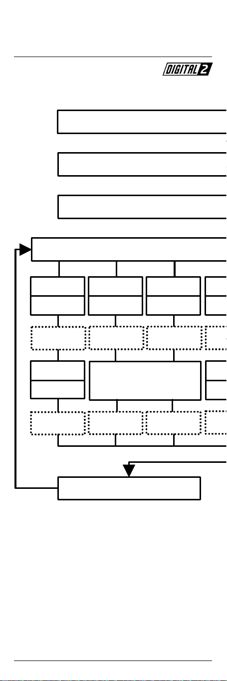
Reprogramming must be completed according to the flow
chart (see page 18/19).
Note:
If the locomotive no longer reacts after reprogramming, then
the locomotive address has probably been reprogrammed.
Incorrect entries can be corrected by resetting the values with
the function 10 (Reset) to the original digital position, i.e.
locomotive address 01, starting and braking 01.
Properties
Locomotive decoder with two direction-dependent function
outputs for DC motors in the Märklin-Motorola format.
• Can be programmed by Intellibox of Control 80.
• The Intellibox can access 255 addresses, other digital
devices 80 addresses.
• 2 different addresses per decoder possible.
• Locomotive addresses, minimum travel voltage, acceleration,
maximum speed and delay can be entered as required.
• All values are saved permanently.
• Pre-set to address 01 and digital operation.
Digital operation
In digital operation, the locomotive runs with the parameters
you have entered. These are permanently saved together with
direction of travel and speed. This means that when the system
is switched on again, a locomotive continues to travel at the
last set speed. In this way, the locomotive can also be used in
block system. If the locomotive in digital operation travels on
an analogue section, you keep the digitally set speed as long as
sufficient voltage is available. It is not possible to change the
direction of travel or increase the travel speed in analogue
sections.
Analogue operation
In analogue operation, the decoder behaves like a direction
switch. The locomotive stops on a digital section.
Selecting the operating mode
There are various methods of changing over between digital
and analogue mode of the decoder.
You can bring the locomotive with the digital decoder to an
16
Page 17

analogue piece of track and put the drive switch of the transformer in the change-over position. After a short time the
decoder then changes over to the other mode: from digital
to analogue after 4 seconds, from analogue to digital after
8 seconds.
The vehicle flashes the rear lights to indicate that the
changeover has taken place. Alternatively, the decoder can be
programmed with function 08 to analogue (value = 01) or
digital (value = 02). (The decoder can also be programmed in
the analogue operating mode, because it recognises the digital
voltage on the piece of track).
Note:
The lighting status adjusted in digital mode is retained in
analogue mode. In other words, if the travelling lights are
switched off in digital mode, they remain off in the analogue
mode.
Compatibility
The module is compatible with the approach braking circuit
for the C90 by Märklin.
Technical data
Addresses: 1 – 255, all accessible via the Intellibox
Max. engine current: 700 mA when the module is placed
Motor starting current: briefly up to 2 A
Function outputs: 900 mA each
Size: 19 x 16 x 5 mm
1 – 80 when another central unit
is being used
loosely in the locomotive or fastened
with an adhesive pad;
1 A when the module is adhered to the
chassis with hot or thermal adhesive
Programming using the Intellibox
The easiest way of programming Uhlenbrock decoders is to
use the Intellibox. The programming mode provides plain text
user guidance through the menu. The exact programming
procedure is described in chapter 9 of the Intellibox manual.
Programming using Loktool
You can programme the decoders in an extremely easy and
convenient manner using our program “Loktool” for Windows
on a PC from 386-25 MHz with connected interface 6050/6051
under Windows 3.x, 95 or NT.
Programming using the Märklin central unit
Connect your control 80/80f to the central unit (6035/6036 +
6020) or connect the control unit (6021) to a section of track
which has only the locomotive being programmed standing
on it.
To program the module, always proceed in the sequence
described on the right. Do not press any other keys.
If the locomotive fails to react after a programming sequence,
then the locomotive address has probably been reprogrammed. Try out all addresses in succession to see when
your vehicle reacts, or use the search function of the Intellibox
or the Loktool program (see the last page). Mistakes can be
corrected by using function 10 to restore the delivered status,
i.e. locomotive address 01, starting and braking 01.
17
Page 18
0
m
v
d
r
c
g
g
m
h
4
m
e
4
Programming Uhlenbrock decoders
Switch transformer off for 1
There is no more interfering
Select loco
This is 01 for e
Press the direction changeover key for 8 secon
Locomotive address
Enter 01
Changeover key
Locomotive lamp
flashes quickly
4 times
Enter 01 – 80
Changeover key Chan
Locomotive lamp
flashes slowly
4 times
Changeover key Changeover key Chan
Locomotive lamp
flashes quickly
The locomotive moves, then confirm
Locomotive lamp
flashes slowly
Programme other functions
This is confirmed by a lamp on t
V min
Enter 02 Enter 03
4 times
Adjust required speed
on drive controller.
Changeover key the Off-key
4 times
V max A
Locomotive lamp
flashes quickly
4 times
Locomotive lamp
flashes slowly
4 times
Call the prog
Loco
flash
Ent
Loco
flas
E
Decoder manual
Comprehensive technical information about our digital decoders
is available from your retailer, including extended programming
instructions (speed curves, possibilities for function keys,
3rd locomotive address).
18
Page 19
seconds, then switch on again.
v
digital information on the track.
otive address.
ery new decoder.
s. The locomotive is now in the programming mode.
he locomotive flashing slowly 4 times.
amming functions
celerate
eover key Changeover key Changeover key Changeover key
otive lamp
es quickly
times
er 01-79 Enter 01-79
eover key Changeover key Changeover key
otive lamp
es slowly
times
Brake
Enter 07 Enter 08
Locomotive lamp
flashes quickly
4 times
Locomotive lamp
flashes slowly
4 times
Enter 80, confirm changeover key
Analogue/Digital
Locomotive lamp
flashes quickly
4 times
01 analogue
02 digital
Locomotive lamp
flashes slowly
4 times
End programming
Reset
Enter 10
Locomotive lamp
flashes slowly
4 times
19
Page 20
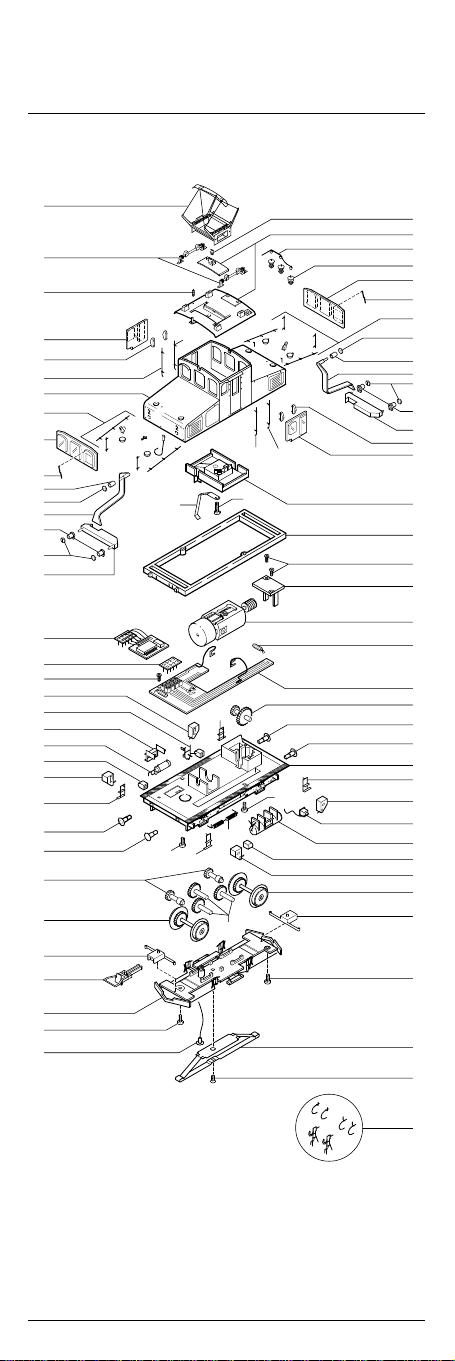
Ersatzteilliste Lokomotive E 69 03
Spare Parts List locomotive E 69 03
Gleichstrom / Wechselstrom D.C. current / A.C. current
01
45
04
06
05
56
57
36
46
42
07
08
39
09
08
40
47
48
18
25
49
11
12
51
52
26
27
28
17
21
15
16
19
18
58
37
56
37
10
14
50
34
50
14
22
20
02
43
44
03
41
42
36
08
07
39
08
09
40
05
38
35
33
18
32
31
55
30
29
28
27
13
26
52
24
23
51
25
21
15
18
53
54
59
20
Page 21

Pos. Bestell Nr. Benennung Description
Order no.
01 0220.02.35 Pantograph Pantograph
02 0220.50.52 Isolator mitte Insulator middle
03 0220.50.53 Isolator Insulator
04 0220.02.30 Signal Pfeife Whistle
05 0220.50.54 Windabweiser Wind Shield
06 0220.50.55 Scheibe links Window left
07 0220.50.22 Stirnlampe head lamp
08 0220.50.56 Lampenglas Lamp glass
09 0220.50.21 Lampe Vorbau Lamp front
10 0220.02.47 Pantograph Kontakt Pick-up pantograph
11 0220.50.12 Aufstieg Step
12 0220.50.13 Kessel klein Tank small
13 0220.50.42 Fahrgestell Chassis
14 0220.02.27 Schraube Gehäuse Screw body
15 0220.50.57 Kupplungsschacht Coupler shaft
16 0550.01.39 Kupplung 2x Coupler 2x
17 0220.50.58 Zwischenrad klein Gear wheel small
18 9955.06.01 Schraube Getriebeabd. Screw gearbox
19 0220.50.02 Getriebeabdeckung kpl. Gearbox cover complete
20 0550.99.22 Zwischenrad groß Gearwheel large
21 0220.50.51 Radsatz DC Wheelstet DC
21* 0221.50.01 Radsatz AC Wheelstet AC
22 0220.50.59 Kühlschlange Cooling
23 0220.50.08 Kessel mit Tritt Tank with step
24 0220.50.03 Tachoantrieb Drive for speedometer
25 0220.50.06 Sandkasten links Sandbox left
26 0220.50.11 Treppe rechts Step right
27 0550.99.20 Puffer rund Buffer round
28 0550.99.21 Puffer flach Buffer flat
29 0470.99.30 Schneckenrad Motor Gearwheel motor
30 0220.50.31 Platine DC PCB DC
30* 0221.50.02 Platine AC PCB AC
31 0220.50.60 Motor komplett Motor complete
32 0220.50.74 Motorhalterung Motor holder
33 0220.50.61 Zwischenrahmen Frame
34 9955.05.03 Schraube Pantograph Screw pantograph
35 0220.50.62 Inneneinrichtung Interior
36 0220.50.63 Anbauteile Vorbau 1+2 Extension parts 1+2
37 0220.50.19 Griffstange Führerhaus Handle cabin left
38 0220.50.64 Scheibe rechts Window right
39 0220.50.65 Lichtleiter Stirnlampe Light bar top
40 0220.50.66 Lichtleiter Vorbau Light bar front
41 0220.50.67 Fenster stirn 1 Window front 1
42 0220.02.34 Wischer Wiper
43 0220.50.50 Dach und Einsatz Roof and cover
44 0220.50.68 Dachleitung klein Roof lead small
45 0220.50.69 Dachleitung groß Roof lead large
46 0220.50.70 Fenster stirn 2 Window front 2
47* 0601.01.70 Digital-Decoder Digitaldecoder
48 0530.99.34 Blindstecker Blind Plug
49 0220.50.04 Radlager Bearing
50 0220.50.10 Treppe links Step left
51 0220.50.05 Radlager Bearing
52 0220.50.07 Sandkasten rechts Sandbox right
53* 0221.50.71 Schleifer AC Pick up AC
54* 9955.06.02 Schraube Schleifer AC Screw pick-up AC
55 3371.99.00 Glühbirne Bulb
56 0220.50.20 Griffstange Führerhaus Handle cabin right
57 0220.50.72 Gehäuse Body
58* 0470.99.31 Pick-up AC Pick up AC
komplett complete
links
rechts
* Bauteil wird nur bei Wechselstrom-Ausführung 0221 verwendet.
This part is only used for AC version 0221.
21
Page 22

Ersatzteilliste Lokomotive E 69 03
Spare Parts List locomotive E 69 03
Pos. Bestell Nr. Benennung Description
Order no.
59 0220.50.01 Zurüstbeutel Extra parts
60 0220.50.73 Fahrgestell komplett Chassis complete
Bestellbeispiel:
Motor komplett mit Position 31 = 0220.50.60 Motor komplett
Order example:
Motor complete with position 31 = 0220.50.60 Motor complete
2x Kupplungsimitat 2x imitation coupling
4x Luftschlauch 4x air hose
22
Page 23
23
Page 24

Brawa Modellspielwarenfabrik GmbH + Co.
Uferstraße 26-28 · D-73630 Remshalden
Telefon 07151 - 97 93 50
Telefax 07151 - 7 46 62
http://www.brawa.de
24
9955.01.86 / 12 5 99 - WAN
 Loading...