

Braun VMAX-MIPI User Manual

2015
BARUN Technology Co.,Ltd.
LEE BYUNG-KWON
[VMAX-MIPI USER'S MANUAL]
This document is provided to whom bought VMAX-MIPI of BARUN Technology..

VMAX-MIPI User’s Manual Ver 1.20
BARUN Technology
Corporation
http://www.baruntechnik.com
VMAX-MIPI User’s Manual Ver 1.20
BARUN Technology
Corporation
http://www.baruntechnik.com
Ver sion 1. 20
May 15, 2015
BARUN Technology Corporation.
http://www.baruntechnik.com

VMAX-MIPI User’s Manual Ver 1.20
BARUN Technology
Corporation
http://www.baruntechnik.com

VMAX-MIPI User’s Manual Ver 1.20
BARUN Technology
Corporation
http://www.baruntechnik.com
Revision History
December 28, 2012 Initial release of the manual
January 2, 2013 Revision 1.1
January 16, 2013 Revison 1.2
MIPI P2BL Pin Assign change
character miss bpio to gpio modify
image.name command add, Chapter 3. Command Set
February 18,2013 Revision 1.3
Output Signal & Power Model VMAX-MIPI-P3BL Add
May 22,2013 Revision 1.3
beep.on bee.off command add, Chapter3.
mipi.write.var1 command add, Chapter3
var1.init, var1.up, var1.down command add, Chapter3
var1.print.on, var1.print, var1.print.off command add
dm600 auto detection(internal function)
May 25,2013 Revision 1.4
dm600.dsoc.x command add, Chapter3
dm600.dsic command add, Chapter3
rgb.dclk / rgb.vsync / rgb.hsync command add, Chapter 3
var1.writer command add, Chapter 3
SSD2828 Register table add, Chapter appendix
July 6, 2013 Revision 1.5
auto convert ELECS initial code to VMAX code
Any error check in initial codes, Chapter 3.1.7
July 18, 2013 Revision 1.6
power.off, mipi.timing.[lp/data/clk] command add, Chapter 3
gpio.link.level convert add, Chapter 3
August 7, 2013 Revision 1.7
mipi.read.show command add, Chapter 3
September 27, 2013 Revision 1.8
mipi.read.iif command add, Chapter 3
December 17, 2013 Revision 1.9
KeyOff, KeyUp, KeyDown, KeyDemo, KeyDemo, KeyF1~F4 control, Ch 3
image command add, Chapter 3
Formal pattern PT84 add

VMAX-MIPI User’s Manual Ver 1.20
BARUN Technology
Corporation
http://www.baruntechnik.com
December 19, 2013 Revision 1.10
Terminal Image OverView window update, Image wait time filed.
May 15, 2015 Revsion 1.20
Commands add of Chapter 3 :
dvm.measure.set.[1/2]
voutcalibration.[1/2]
pwr.current.span.[1/2]
gpio.mode.[4/5/6], SectionGPIO [4/5/6], EndOfSectionGPIO[4/5/6]
var1.mipi.write
mipi.sleep.[enable/disable]
KeyOn.run
KeyOff.run
KeyUp.run
KeyDown.run
KeyF1.run
KeyF2.run
KeyF3.run
KeyF4.run

VMAX-MIPI User’s Manual Ver 1.20
BARUN Technology
Corporation
http://www.baruntechnik.com
TABLE OF CONTENTS
1. Product introduction ............................................................................................................. 1
1.1. Outline ........................................................................................................................................ 1
1.2. VMAX-MIPI block diagram ......................................................................................................... 1
1.3. VMAX-MIPI Specification ........................................................................................................... 2
1.4. Equipment overview ................................................................................................................... 3
1.4.1. Power Jack, USB Jack, MIPI-FHD Port side ....................................................................... 3
1.4.2. Top side ................................................................................................................................ 4
2. Windows VMAX-Terminal .................................................................................................... 5
2.1. Installation .................................................................................................................................. 6
2.2. Composition of window .............................................................................................................. 7
3. Command SET .................................................................................................................. 15
3.1. Commands List ........................................................................................................................ 15
3.1.1. MIPI-FHD Bridge (HS-Video) Example .............................................................................. 40
3.1.2. MIPI-FHD Bridge (HS-Command) Example ...................................................................... 41
3.1.3. MIPI-FHD Bridge (LP-Command) Example ....................................................................... 42
3.1.4. MIPI-FHD Bridge (Read Operation) Example (Command mode) ..................................... 43
3.1.5. SPI Bridge (Read Operation) Example .............................................................................. 44
3.1.6. MIPI-FHD Image types ...................................................................................................... 44
3.1.7. Auto convert ELECS initial code & error check. ................................................................. 46
3.1.8. MIPI Read (mipi.read.iif) Example ..................................................................................... 50
3.1.9. MIPI Read(mipi.read.iif) SubRoutine Example .................................................................. 51
3.1.10. MIPI Read (mipi.read.iif) Example ................................................................................... 51
3.1.11. GPIO Input(gpio.mode.[4/5/6/) SubRoutine Example ...................................................... 53
4. Output Signals & Power..................................................................................................... 54
4.1. MIPI-FHD Output signal ........................................................................................................... 54
5. Appendix ............................................................................................................................ 55
5.1. MIPI-DCS (Display Command Set).......................................................................................... 55
5.2. Typical Patterns ....................................................................................................................... 58
5.3. SSD2828 MIPI bridge Register Summary ............................................................................... 73
5.4. Technical Notes ........................................................................................................................ 75
5.4.1. Command script text limitations. ........................................................................................ 75
5.4.2. UPLS Support .................................................................................................................... 76

VMAX-MIPI User’s Manual Ver 1.20
BARUN Technology
Corporation
http://www.baruntechnik.com
VMAX-MIPI User’s Manual 1 Ver 1.20
BARUN Technology
Corporation
http://www.baruntechnik.com
1. Product introduction
1.1. Outline
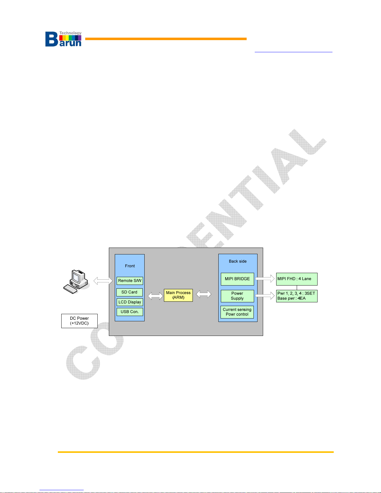
VMAX-MIPI is a pattern generator which supports Full-HD resolution. VMAX-MIPI has one MIPI
connector (29pin), 4 programmable power outputs.All power channels are measured in real time.
Bundle software which provided is proper with Windows XP or Windows 8. That software
called“VMAX_Terminal”. VMAX_Terminal can control VMAX’s every function. User can download
model information, instructions and images for module test by VMAX_Terminal. Several status
information and voltage values of VMAX are displayed on PC’s monitor in real time.
1.2. VMAX-MIPI block diagram
VMAX-MIPI User’s Manual 2 Ver 1.20
BARUN Technology
Corporation
http://www.baruntechnik.com
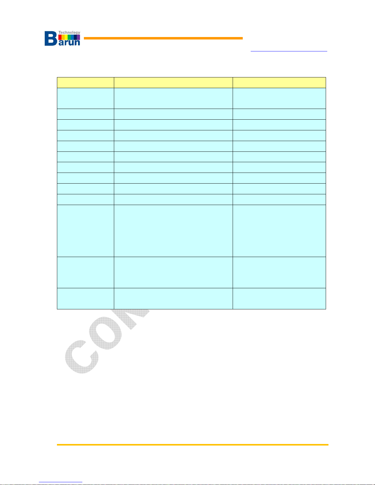
1.3. VMAX-MIPI Specification
Items Specification Remark
Input power +12VDC/1.5A
Current Consumption :
Type : 350mA, Max : 1.5A
PC Interface USB 2.0
SDRAM 256MB SDRAM
SD Card 2GB
NAND Flash 256MB
Compatibility Max, 24bit(16M color)
Signal interface MIPI Full HD interface (RGB Port used) MIPI FHD : 1GBPS
Connector MIPI Full HD : HDMI 29Pin con. Max 1Gbps 4 Lane
Model change USB download USB 2.0
Moving picture Available H264(ES) Format support
Output Power Power 1 : 1.2V ~ 9V / 0.1V step
Power 2 : 1.2V ~ 9V / 0.1V step
*Power 3 : 1.2V ~ 9V / 0.1V step (LED-)
*Power 4 : 1.2V ~ 9V / 0.1V step (LED+)
**Power 5 : 1.2V ~ 9V / 0.1V step
6Watt / MAX
6Watt / MAX
*6Watt / MAX (Cathode)
*6Watt / MAX (Anode)
**6Watt / MAX
RGB interface
(MIPI Bridge)
Max. 15 model selectable
Max 4000 images (based on 128 X 128)
Max 840 images (based on 240 X 320)
Current
measuring
Channel 4 x 1 block
* Note : VMAX-MIPI-P2BL model support in Back Light power(20mA). (LED+,LED-)
** Note : Only VMAX-MIPI-P3FBL model support.
VMAX-MIPI User’s Manual 3 Ver 1.20
BARUN Technology
Corporation
http://www.baruntechnik.com
1.4. Equipment overview
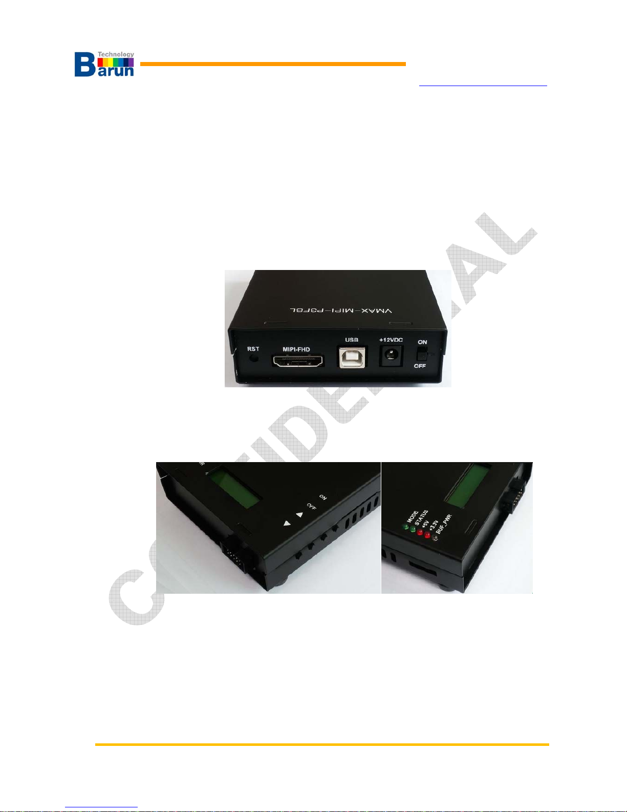
1.4.1. Power Jack, USB Jack, MIPI-FHD Port side
Reset button, MIPI-FHD connector, USB connector, DC power input and Power ON/OFF
switch are placed at front panel.
There are four buttons: ON / OFF / Image up / Image Down
VMAX-MIPI User’s Manual 4 Ver 1.20
BARUN Technology
Corporation
http://www.baruntechnik.com
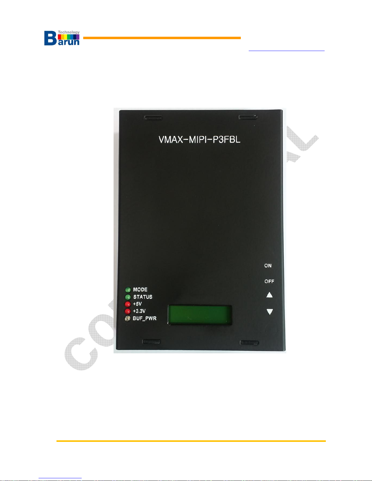
1.4.2. Top s id e
There are two line character LCD and 5 color LED. VMAX’s status displayed at line
character.

VMAX-MIPI User’s Manual 5 Ver 1.20
BARUN Technology
Corporation
http://www.baruntechnik.com
2. Windows VMAX-Terminal
VMAX-Terminal is software to control and manage data ofVMAX. VMAX-Terminal can control
whole VMAX function and edit module data.
Features summary :
z Manage mode data, edit / make / delete / rename / copy / save.
z uSD Card Memory Check function.
z Remote power monitoring.
z Windows editor software define.
z A fixed typical pattern support.
z Display Firmware Version / Serial Number / Model Name
z Display Image Overview.
z Support for real-time command to transfer
z Monitor Current sensing activate when module turn on.
z Stored for real-time command and VMAX response message.
z Video file download and delete.
z VMAX in four buttons, and the DEMO button.
z Operation status is displayed as a message.

VMAX-MIPI User’s Manual 6 Ver 1.20
BARUN Technology
Corporation
http://www.baruntechnik.com
2.1. Installation
VMAX installation is very easy. Just click VMAX_Term_Setup.exe in CD-ROM.
When user click VMAX_Terminal_Setup.exe ,setup program make directory
“C:\VMAX\VMAX_MIPI” and every data copied under the directory..
VMAX-MIPI User’s Manual 7 Ver 1.20
BARUN Technology
Corporation
http://www.baruntechnik.com
2.2. Composition of window
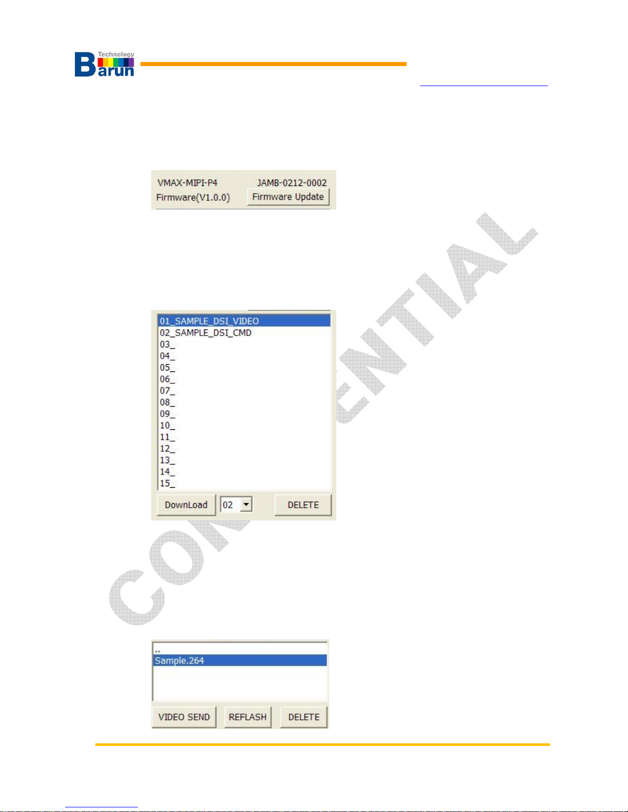
VMAX Information
This window is VMAX model, serial number, firmware version.
Button for Firmware Update to firmware change.
Model catalog / Download / Delete
Model of this window within the VMAX
DownLoad button a list of the desired model is available for download.
Want to DELETE button to delete the list of models.
Video file transfer and delete
VMAX-MIPI User’s Manual 8 Ver 1.20
BARUN Technology
Corporation
http://www.baruntechnik.com
uSD memory card VMAX in the window showing the video file
VIDEO SEND button, you can transfer the video files you want.
VIDEO directory REFLASH button, check again.
Want to DELETE button to delete the video file.
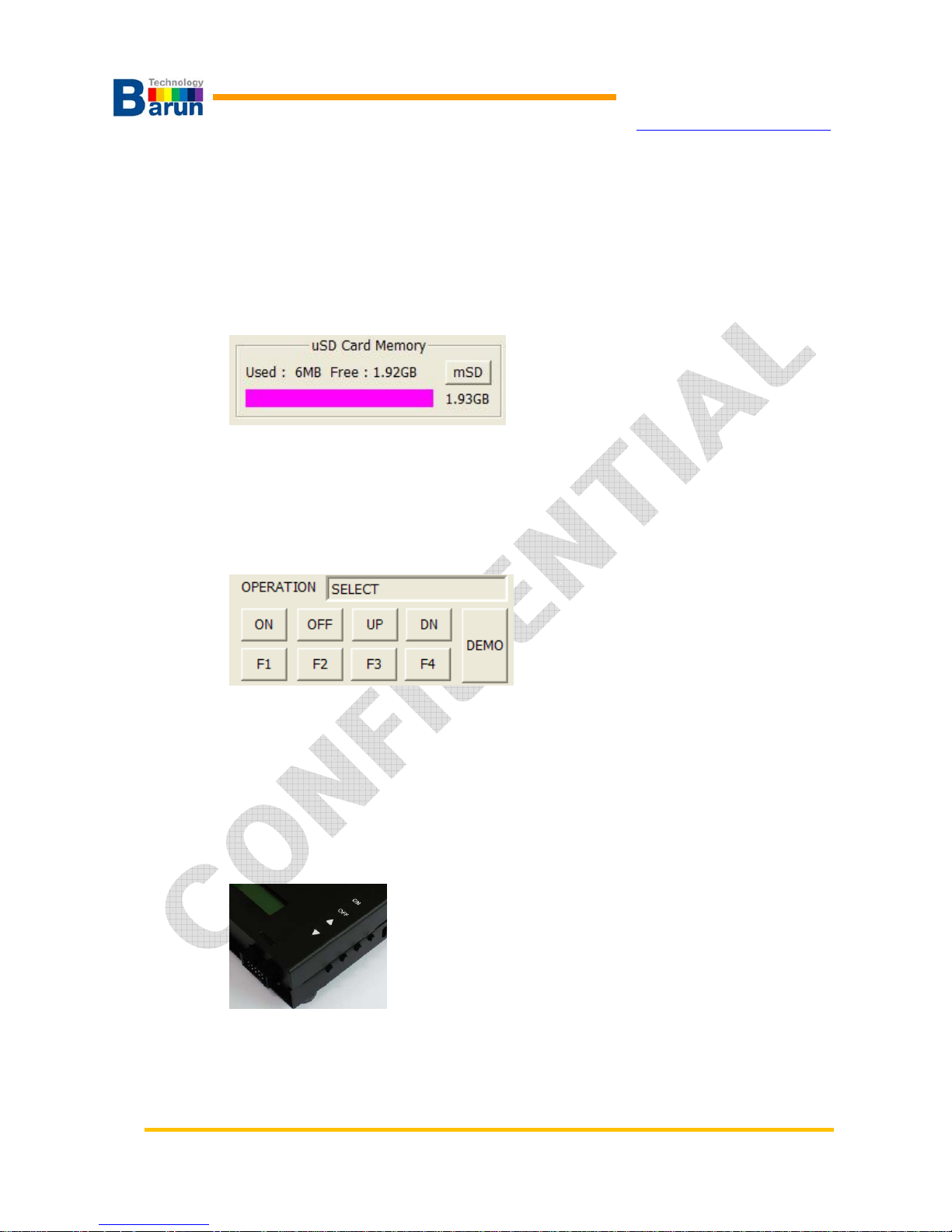
SD Card memory Check
uSD memory capacity in the part of the VMAX is a window showing.
mSD button is pressed, this information can be confirmed.
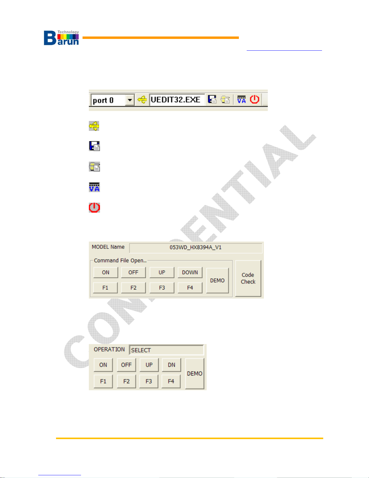
Remote Keypad / Operation message
OPERATION is 3 status of READY / ON / SELECT.
When the READY state VMAX ON key is pressed once, ME(measure)mode indicates that.
VMAX’s ON key is pressed two times, ME-ON mode ON state indicates that.
VMAX of the state OFF select key is pressed, SE(Select model)mode indicates that.
Five remote USB port using virtual key pads.
This button is the same function with the keys on the side of the VMAX
DEMO button that runs in the ME-ON state should run the command key DEMO.txt
VMAX-MIPI User’s Manual 9 Ver 1.20
BARUN Technology
Corporation
http://www.baruntechnik.com
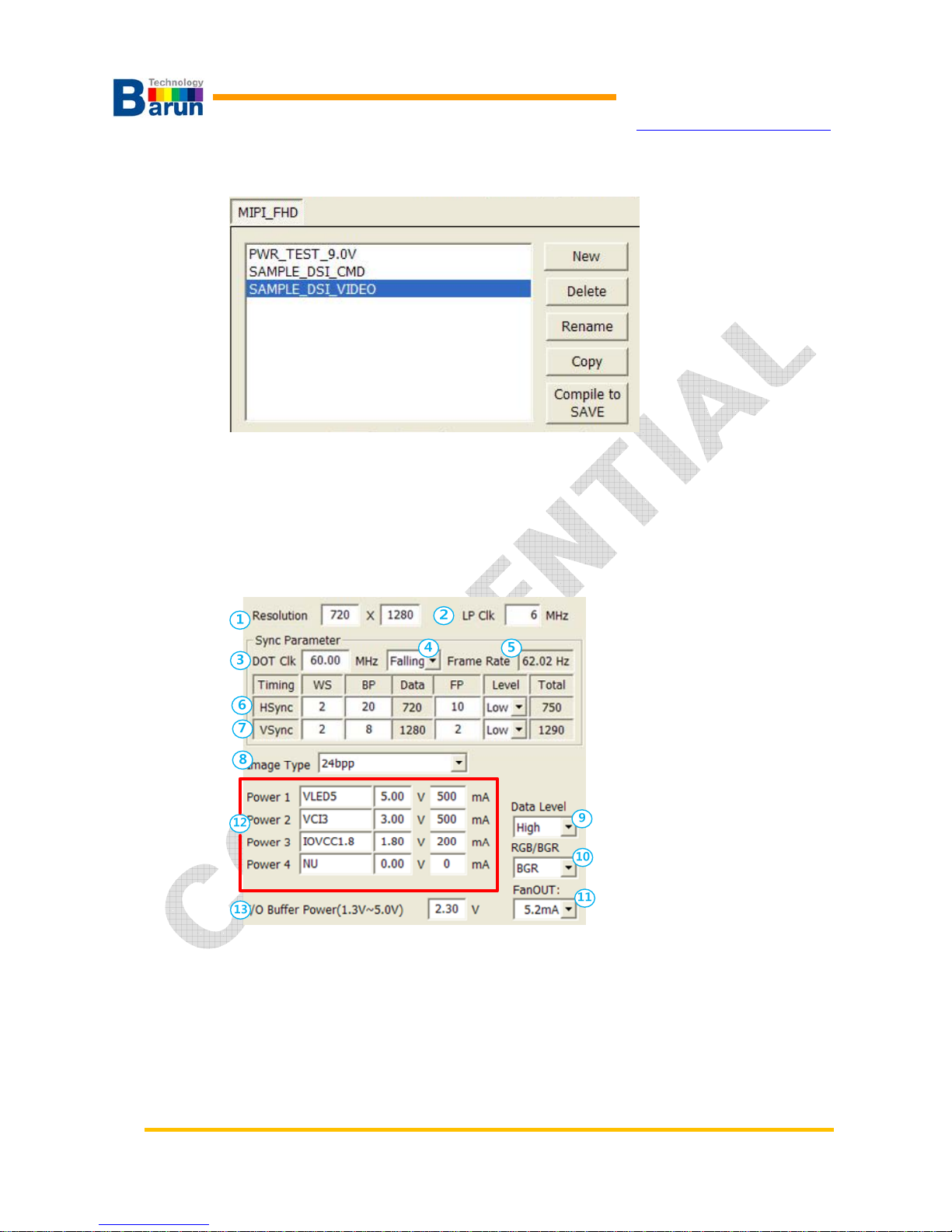
Display Model data Create / Delete / Rename / Copy / Compile to SAVE
Display model data, part of the delete, rename, copy, and save(interpretation).
(*After the change, or created or copied the “Compile to SAVE” to.)
Data can be read by double-clicking on the list.
Sync Parameters
○
1
Resolution
○
2
LP Clk: Low power mode clock for commend sending
○
3
DOT Clk:base clock frequency for display image.
○
4
Data Latch Timing: rising edge or falling edge to latch data.
○
5
Frame Rate: How many frame image display per second
○
6
Set HWS, BP(Back Porch),FP(Front Porch)and Level of Hsync.
○
7
SetVWS, BP(Back Porch),FP(Front Porch)and Level of Vsync.
VMAX-MIPI User’s Manual 10 Ver 1.20
BARUN Technology
Corporation
http://www.baruntechnik.com
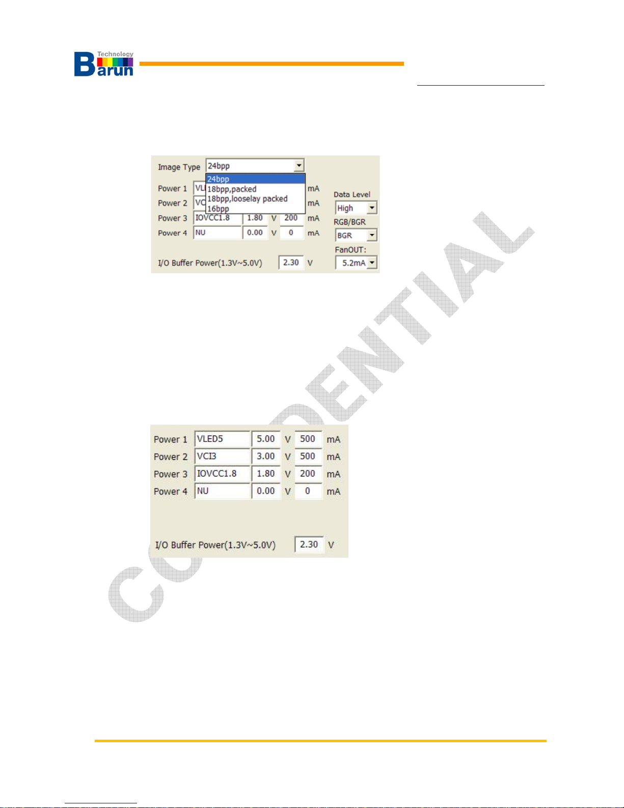
○
8
Image Type: Select image Type
User can select one image type. Click pull-down button of “Image Type”, 4 image
format show as following picture. See Chapter 3 for detail of “Image Type”.
○
9
Set Data Level: High or Low
○
10
Set pixel sequence: RGB or GRB
○
11
Fan Out: Set “Fan out” of RGB data line of the processor.
○
12
Set power channel: Set channel name, voltage, currnet.
○
13
Set voltage of general purpose I/O.
Power settings
This section to set the power output to the display module.
*VMAX products, depending on the model, you can receive each of the 2-channel /
4-channel / 6-channel.
Range of voltages and currents set also can vary depending on the model VMAX
product. Therefore specifications required.
I/O Buffer Power part of the MIPI-GIPIO pin to set the output voltage.
VMAX-MIPI User’s Manual 11 Ver 1.20
BARUN Technology
Corporation
http://www.baruntechnik.com
Command file edit
Editor in the EDITOR field, as shown in the figure below are links to.
. :
USB Port Reconnection ICON.
Save information the editor software.
Browse editor software ICON.
Power Monitor window open ICON.
Terminal program quit ICON.
Gives five command editor to open the linked file.
Each of the five Key Remote key corresponding to the command file.
In other words, ON Key file is executed by pressing the ON key file is executed by
pressing the OFF key.
Image Over-View
VMAX-MIPI User’s Manual 12 Ver 1.20
BARUN Technology
Corporation
http://www.baruntechnik.com
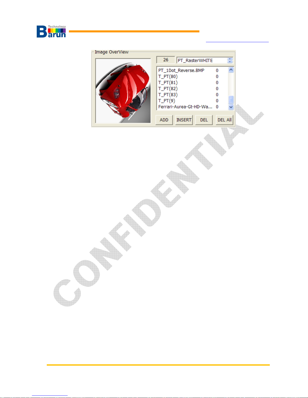
○
1
Image list: Show image list what you select to download.
○
2
Image Number: Display selected image and it’s number.
○
3
Add: Add test image.
○
4
Insert: Insert test image between exist images.
○
5
Remove: Remove selected image.
○
6
Remove All: Remove all images in the list.
○
7
List Mouse Right click the Wait time set.
** Test Patters add: Double click.
Image List window shows registered test images. When you select any test image name,
the selected pattern displayed at left pattern view window.
There are several function keys to help easy editing.
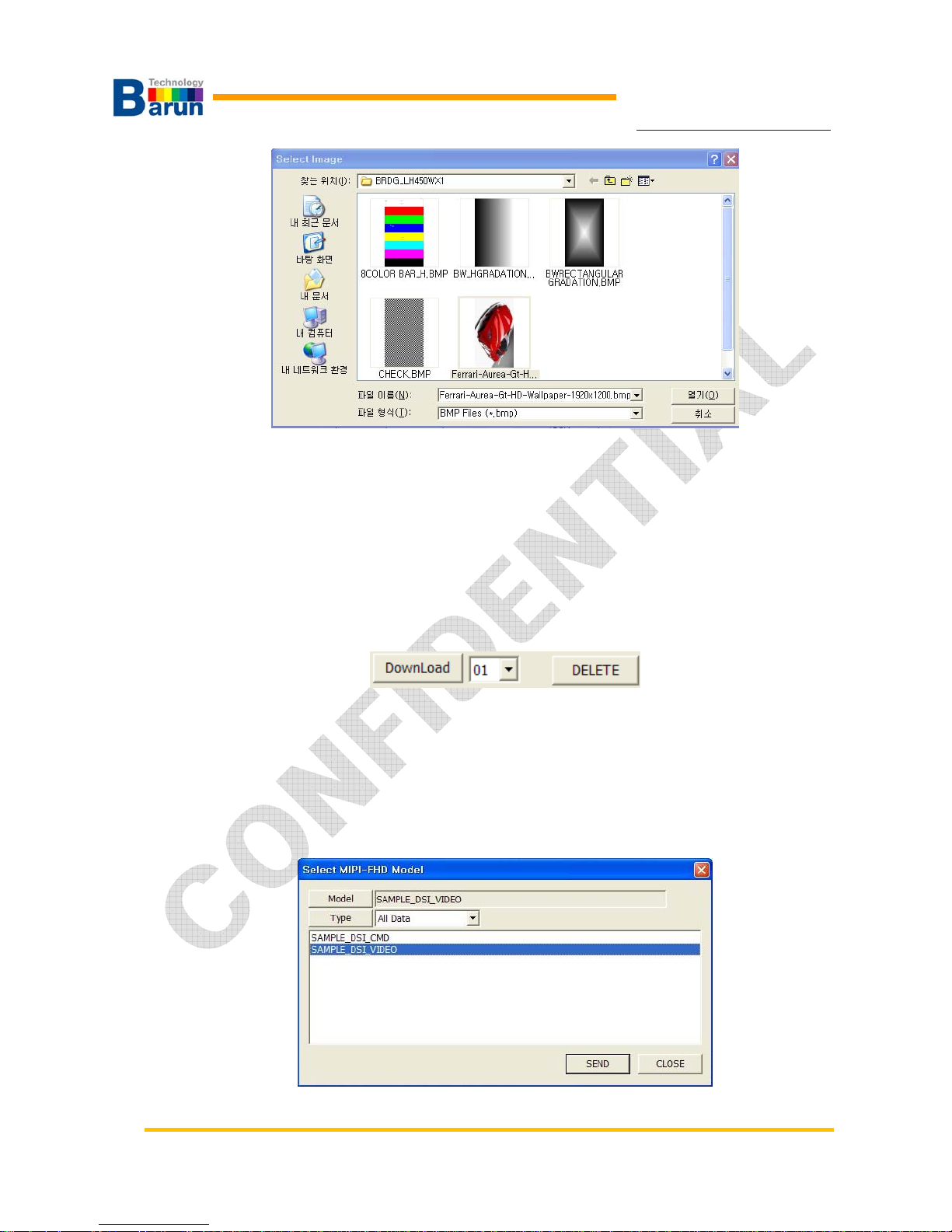
“Select Image” window appeared when you click “Add”.
If you already saved test patterns under test model directory, you can see whole
patterns. And just select what you want and select “Open”.
VMAX-MIPI User’s Manual 13 Ver 1.20
BARUN Technology
Corporation
http://www.baruntechnik.com
Download and Delete
User can download model data to SD card of VMAX-MIPI.15 model data could be store
to SD card. Select number from 1 to 15 and click “DownLoad”.
Now a window popped titled “Select MIPI-FHD Mode”. User select can select model and
type. There are three types: (1) All Data, (2) Information, Instruction, (3) Image.
Check USB cable before download model data.

VMAX-MIPI User’s Manual 14 Ver 1.20
BARUN Technology
Corporation
http://www.baruntechnik.com
A. Select main module data and click “Model” button
B. Select data type among ALL DATA, Image, Information/Instruction
C. Chose main model data what you want to download
D. OK: Start download.
E. Cancel: Exit without download.

VMAX-MIPI User’s Manual 15 Ver 1.20
BARUN Technology
Corporation
http://www.baruntechnik.com
3. Command SET
3.1. Commands List
MIPI bridge circuit connected to RGB data lines and HS, VS, DE, CLK.
Several instructions are ready. Following table shows MIPI instructions which support MIPI
bridge board.
No. Type Description Para.
1 mipi.board.on Bridge board active. Non
2 mipi.board.off Bridge board shutdown. Non
3 mipi.board.reset Bridge board reset. Non
4 board.reset Bridge board reset Non
5 mipi.gpio0 Set module connector pin 16 ON(1) or OFF(0) 1
6 mipi.gpio1 Set module connector pin 18 ON(1) or OFF(0) 1
7 mipi.gpio2 Set module connector pin 19 ON(1) or OFF(0) 1
8 mipi.gpio3 Set module connector pin 21 ON(1) or OFF(0) 1
9 mipi.gpio4 Set module connector pin 24 ON(1) or OFF(0) 1
10 mipi.gpio5 Set module connector pin 25 ON(1) or OFF(0) 1
11 mipi.gpio6 Set module connector pin 26 ON(1) or OFF(0) 1
12 mipi.write Send MIPI packet.
13 mipi.read Read MIPI module register access. 3
14 mipi.dsi Set MIPI dsi configuration 3
15 mipi.clock.enable Enable MIPI clock output. Non
16 mipi.clock.disable Disable MIPI clock output. Non
17 mipi.video.enable Enter the MIPI video mode Non
18 mipi.video.disable Exit the MIPI video mode. Non
19 mipi.hs.enable Enable MIPI HS mode. Non
20 mipi.hs.disable Disable MIPI HS mode. Non
21 pwrport.on Set module power on the VMAX-MIPI 1~6
22 pwrport.off Set module power off the VMAX-MIPI 1~6
23 pwrbase.on Set Bridge board control signal buffer power ON. Non
24 pwrbase.off Set Bridge board control signal buffer power OFF. Non
25 rgb.sync.enable Enable RGB data output and sync on. Non
26 rgb.sync.disable Disable RGB data output and sync off. Non

VMAX-MIPI User’s Manual 16 Ver 1.20
BARUN Technology
Corporation
http://www.baruntechnik.com
27 image.display
number
Display specific image number 1
28 image.first Display first image NON
29 image.next Display next image NON
30 image.prev Display previous image NON
31 image.repeat
sec
Display image repeatedly 1
32 board.power.on led Set module Back-light on(VMAX-MIPI-P2BL only) Non
33 board.power.off led Set module Back-light off(VMAX-MIPI-P2BL only) Non
34 mipi.lane.enable Lane Enable : Hi-Z -> STOP state(LP11) Non
35 spi.bridge.write Bridge chip Register write command
36 spi.bridge.read Bridge chip Register read command
37 wait Delay time 1
38 loop Repeat command from loop to loopend n times 1
39 loopend Terminate loop command Non
40 image.name.on Image file name display on Non
41 image.neme.off Image file name display off Non
42 image.name Image file name display option 5
43 beep.on Buzzer beep on Non
44 beep.off Buzzer beep off Non
45 mipi.write.var1 Send MIPI packet with variable data field set
46 var1.init Variable mipi data field initilize 3
47 var1.up Variable increase value 1
48 var1.down Variable decrease value 1
49 var1.print.on Variable mipi data display enable command Non
50 var1.print.off Variable mipi data display disable command Non
51 var1.print Variable mipi data display position 5
52 dm600.dsoc.1 dm600 Card slot#1, skew control command 7
53 dm600.dsoc.2 dm600 Card slot#2, skew control command 7
54 dm600.dsoc.3 dm600 Card slot#3, skew control command 7
55 dm600.dsoc.4 dm600 Card slot#4, skew control command 7
56 dm600.dsoc.5 dm600 Card slot#5, skew control command 7
57 dm600.dsoc.6 dm600 Card slot#6, skew control command 7
58 dm600.dsic dm600 DVI Input, reg control command 4
59 rgb.dclk rgb dot clock change command 1
60 rgb.hsync rgb vsync parameter change command 3
61 rgb.vsync rgb hsync parameter change command 3
62 var1.write Variable mipi data send the latest variable. Non

VMAX-MIPI User’s Manual 17 Ver 1.20
BARUN Technology
Corporation
http://www.baruntechnik.com
63 power.off all Set module power off all the VMAX-MIPI Non
64 gpio.link.level VMAX Terminal, I/O Buffer power voltage level 1
65 mipi.timing.lp LP Clock Timing control command 4
66 mipi.timing.data HS Data Timing control command 4
67 mipi.timing.clk HS Clk Timing control command 4
68 mipi.read.show Read MIPI module register data display. 6
69 mipi.read.show.set Read data display position, Font, set command 5
70 mipi.read.show.off Read data display disable command Non
71 mipi.read.iif Read MIPI module register data display function 2 9
72 SectionTRUE Compare routine start of mipi.read.iif read data 1
73 EndOfSectionTRUE Compare routine end of mipi.read.iif read data 1
74 SectionFALSE Compare routine start of mipi.read.iif read data 1
75 EndOfSectionFALSE Compare routine end of mipi.read.iif read data 1
76 beep Buzzer control on and beep sound 1
77 KeyOff.enable OFF Key press enable control Non
78 KeyOff.disable OFF Key press disable control. Non
79 KeyDown.enable DOWN/PREV Key press enable control Non
80 KeyUp.disable UP/NEXT Key press disable control Non
81 KeyDown.enable DOWN Key press enable control Non
82 KeyDown.disable DOWN Key press disable control Non
83 KeyDemo.enable DEMO Key press enable control Non
84 KeyDemo.disable DEMO Key press disable control Non
85 KeyF1.enable F1 Key press enable control Non
86 KeyF1.disable F1 Key press disable control Non
87 KeyF2.enable F2 Key press enable control Non
88 KeyF2.disable F2 Key press disable control Non
89 KeyF3.enable F3 Key press enable control Non
90 KeyF3.disable F3 Key press disable control Non
91 KeyF4.enable F4 Key press enable control Non
92 KeyF4.disable F4 Key press disable control Non
93 image Fill pattern <R0~255>, <G0~255>, <B0~255> Non
94 dvm.measure.set.1 power port1 output volt offset input command 1
95 dvm.measure.set.2 power port2 output volt offset input command 1
96 voutcalibration.1 power port1 output volt auto calibration command Non
97 voutcalibration.2 power port2 output volt auto calibration command Non
98 pwr.current.span.1 power port1 output current span offset command 1

VMAX-MIPI User’s Manual 18 Ver 1.20
BARUN Technology
Corporation
http://www.baruntechnik.com
99 pwr.current.span.2 power port2 output current span offset command 1
100 gpio.mode.4 mipi.gpio4 port input/output set command 1
101 gpio.mode5 mipi.gpio5 port input/output set command 1
102 SectionGPIO Compare routine start of gpio[4/5/6] level HIGH 1
103 EndOfSectionGPIO Compare routine end of gpio[4/5/6]. 1
104 var1.mipi.write var1 value mipi write command. Non
105 mipi.sleep.enable Enter Ultra Low power state. Non
106 mipi.sleep.disable Exiting from the ULPS Non
107 KeyOn.run On Key script run command Non
108 KeyOff.run Off Key script run command Non
109 KeyUp.run Up Key script run command Non
110 KeyDown.run Down Key script run command Non
111 KeyF1.run F1 Key script run command Non
112 KeyF2.run F2 Key script run command Non
113 KeyF3.run F3 Key script run command Non
114 KeyF4.run F4 Key script run command Non
 Loading...