

Braun Under-Vehicle Lift NUVL603C Service Manual
Service Manual for:
CJKA+%(8
CJKA+%(8
Under-Vehicle Lift
®
Private Use Wheelchair Lifts
www.braunlift.com
Series 02
DOT — Private Use Lift
DOT — Private Use Lift
“DOT — Private Use Lift” verifies that this platform lift meets only
the “private use lift” requirements of FMVSS No. 403. This lift may
be installed on all vehicles appropriate for the size and weight of
the lift, except for buses, school buses, and multi-purpose
passenger vehicles other than motor homes with a gross vehicle
weight rating (GVWR) that exceeds 4,536 kg (10,000 lb).
02
W
A
R N I N G
Man
ual
"Providing Access to the World"
International Corporate Hdqrs: P.O. Box 310 Winamac, IN 46996 USA
1-800-THE LIFT
35033
November
2008
®
(574) 946-6153 FAX: (574) 946-4670
®
®
Patent #5,305,486
Patent #5,305,486
Read manual
before installing
or servicing lift.
Failure to do so
may result in
serious bodily
injury and/or
property damage.
Braun UVL SeriesTM
Braun UVL SeriesTM

OWNER'S WARRANTY REGISTRATION
PURCHASED FROM
DATE INSTALLED
NAME
ADDRESS
CITY
TELEPHONE
TO VALIDATE WARRANTY
REGISTRATION CARDS MUST BE RETURNED TO THE BRAUN CORPORATION.
OWNER
STATE ZIP
Congratulations
We at The Braun Corporation wish to express our fullest appreciation
on your new purchase. With you in mind, our skilled craftsmen have designed and
assembled the finest lift available.
This manual provides service-related material. Refer to the FMVSS No. 403
Quick Reference Installation Sheet for installation instructions, operating instructions
and maintenance procedures.
Braun UVL Series™ lifts are built for dependability and will provide years of pleasure and independence as long as the lift is installed and serviced as specified by a
Braun certified technician, and the lift is operated by an instructed person.
Sincerely,
THE BRAUN CORPORATION
Ralph W. Braun
Chief Executive Officer
Warranty and Registration Instructions
Immediately upon receiving the lift, examine the
unit for any damage. Notify the carrier at once
Series No.
Serial No.Model No.
with any claims.
NUVL603C 02-00025
Two warranty/registration cards (shown right) are
protected in a clear envelope and attached to the
lift protective shipping wrap. The sales representative must process one of the cards. The consumer
must fill out the other card and mail it to The Braun
Corporation. A detailed warranty section is provided
in this manual. The warranty cards must be
Sample Warranty/Registration Card
processed to activate the warranty.
Two Braun Serial No./Series No. identification tags (shown below) are posted on the lift. One
I.D. tag is posted on the left platform side plate (outboard end). A second I.D. tag is located
inside of the pump module. Both I.D. tags provide the product identification information
provided on the warranty/registration card. Record the information in the space provided (or
document on a copy). This information must be provided when filing a warranty
claim or ordering parts.
The Braun Corporation
1-800-THE-LIFT
BRAUNMOBILITY.COM
DOT Private Use Lift MODEL#
NUVL603C
Max. Lifting Capacity - 750Lbs.
SERIAL NUMBER
02-00025
®
®
Model No.
Series No.
Serial No.
MFG DATE
11/12/2007
e5*72/245*95/54*0102*00
Sample Serial No./Series No. Identification Tag
PATENT
5,305,486
Pump Code
Cylinder Code
Date of Manufacture

Contents
Troubleshooting and Maintenance
Lift Terminology ............................................................ 2
Switch and Sensor Locations ..................................... 3
Certification Checklist .................................................. 4
Adjustments and Calibration ....................................... 5
LCD Diagnostic Codes ................................................. 6
Floor Level and Inboard Locator Adjustments ..... 7-10
Lubrication Diagram ....................................................11
Maintenance and Lubrication Schedule ............... 12-14
Troubleshooting Diagnosis Chart ......................... 15-18
Notes ............................................................................ 19
Lift Wiring Schematic - Main ..................................... 20
Lift Wiring Schematic - Accessories ........................ 21
Hydraulics
Hydraulics Parts List .................................................. 22
Hydraulics Diagram .................................................... 23
Repair Parts
Pump Module
Pump Module Parts List ....................................... 24
Pump Module Diagram ......................................... 25
Lift Exploded Views
Complete Lift .......................................................... 26
Repair Parts List ................................................... 27
Housing Detail ........................................................ 28
Carriage Detail........................................................ 29
Platform Detail ........................................................ 30
Warranty
®
Braun
Limited Warranty .......................................31-33
Notes ............................................................................ 34
Page 1
Hand-Held Attendant's
Control Box
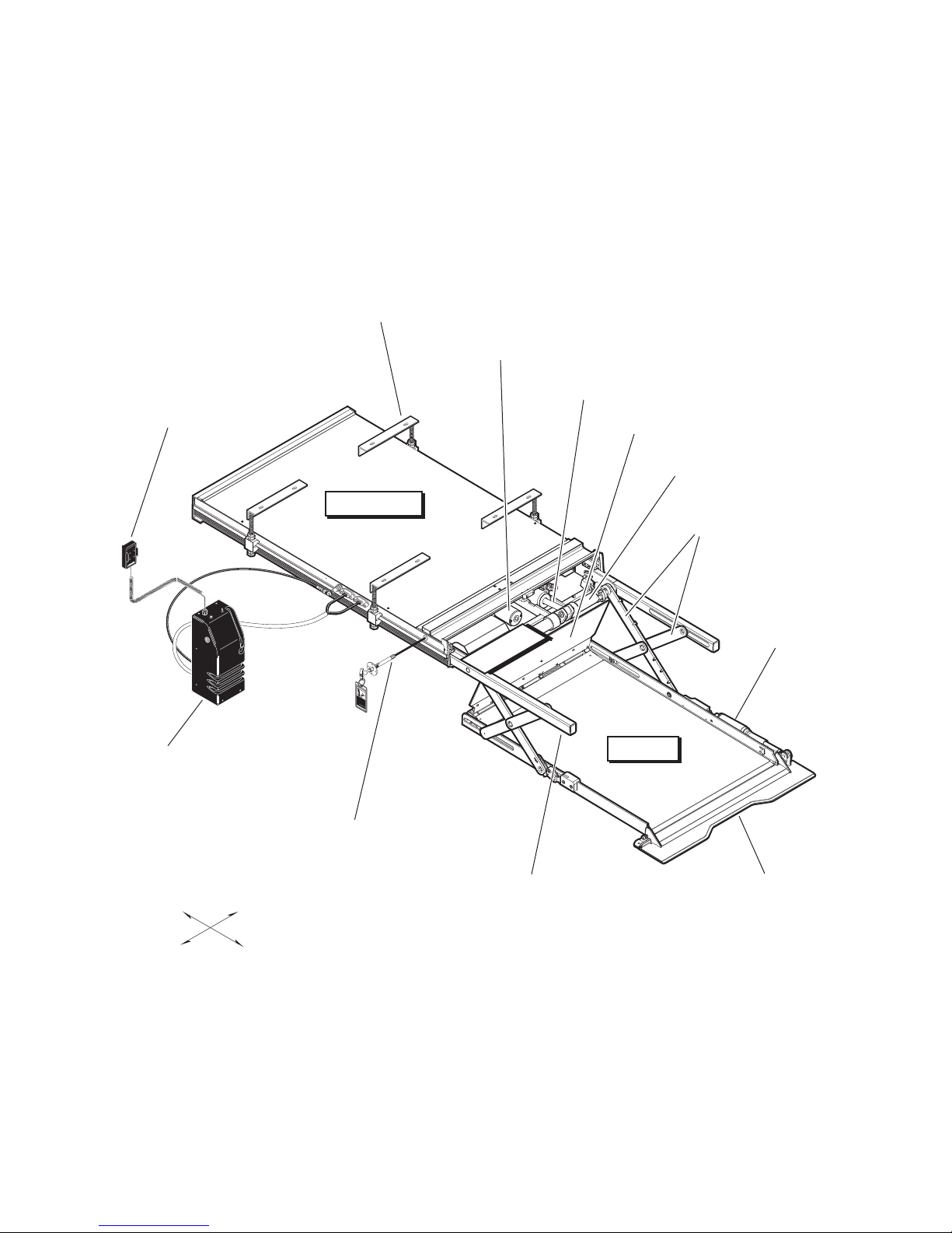
Lift Terminology
Lift Mounting
Brackets (4)
Chain Drive
Motor
Hydraulic
Cylinder
Inboard
Locator
Torque
Tube
STOW
R
DOO
P
U
N
DOW
Module
Pump
Inboard
Lift Housing
Platform Cable-activated
Manual Release System
Right
Lifting
Arms
Outer Barrier
Actuator
Carriage
W
A
R
N
I
N
G
P
u
sh
ma
T
h
n
a
ual
n
and ou
dl
l
y m
e in
lock b
ove
t t
f
u
o
lly
Fa
platform in
e
ef
n
a
ilure to lock platfo
nd
o
gage pla
re dr
re
s
u
i
vi
l
t
deploy
n
t
i
f
n
g
o
vehi
u
r
m
nint
platform d
m
cl
e
e
e.
nt. Unintended
n
rm
r
d
e
sult
ed pla
ma
eployment
a
y
i
n
n
d/or p
t
se
f
o
rm
riou
roper
s
m
bo
a
ty da
y
dil
y
injury
Do not remove!
m
a
g
e
.
8
1
8
23
Platform
Rolling
Horizontal Arms
Outer
Barrier
Left
Outboard
Page 2
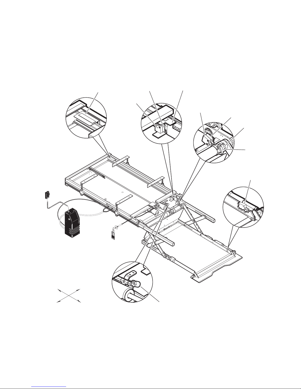
Switch and Sensor Locations
Lift Out
Cam
73774
Lift Out
Limit Switch
73950A
Full Out
Limit Switch
73950A
Full Out
Cam
73775
Below Stow
Limit Switch
73950A
Floor Level
Limit Switch
73950A
Floor Level
Cam
73712
Below Stow
Cam
73712
Outer Barrier
Limit Switch
73950A
STOW
DOOR
UP
OWN
D
Inboard
Left
Right
Outboard
W
A
R
N
I
N
G
Pu
sh
Tm
a
h
n
a
uall
n
an
dle
d
y
o
m
i
n
l
ut to
o
o
f
c
ve
u
k
l
l
b
pl
y a
Fa
en
ef
a
i
nd
o
g
l
tf
u
re
a
o
r
result in
g
e to
rm
e plat
d
r
i
i
v
n
l
d
i
o
n
ep
c
f
g
o
k pl
unin
r
l
ve
o
m
plat
yment
hi
a
t
t
cle.
f
e
o
f
o
n
r
r
r
m
ded
e
m
.
sult in
Uni
m
de
a
p
an
y
p
lat
n
l
d/o
t
o
e
se
fo
yment may
n
r
r
d
r
m
i
pr
ed
o
u
o
s
p
bo
e
r
t
d
y
ily
d
amage
Do
inju
not rem
ry
.
81
8
2
3
ov
e!
Pressure
Transducer
30426
Page 3

Certification Checklist
The following operations and conditions must be functionally verified in order for the lift to be FMVSS
403/404 compliant. If an operation does not function as described or a condition is not met, follow the referenced procedures to correct the problem or contact a Braun Corporation Product Support representative.
• Vehicle movement is prevented unless the lift door is closed, ensuring the lift is stowed.
1. Verify lift stowed signal (pin 9) in the 9 conductor plug on the side of the pump module has a +12 volt
signal.
2. Refer to the interlock installation instructions.
• Lift operation shall be inhibited unless the vehicle is stopped and vehicle movement is prevented.
1. Verify vehicle secure signal (pin 6) in the 9 conductor plug on the side of the pump module has a +12
volt signal.
2. Refer to the interlock installation instructions.
• The platform will not fold/stow when occupied.
- Refer to Platform Sense Calibration.
• The outer barrier will not raise if occupied.
- Refer to Outer Barrier Occupied Calibration procedure
• An audio warning (and visual warning for public use lifts) will activate if the threshold area is occupied
when the platform is a least 1" below floor level.
1. Make sure connectors to threshold mat are properly connected.
2. Call Product Support.
• Lift platform movement shall be interrupted unless the outer barrier is deployed (up).
- Check Barrier Down limit switch, wires and connector.
- Diagnostic LCD should display a value of “1” for OBAR SW when outer barrier is deployed (up).
Page 4

Adjustment Procedures
Adjustments and Calibration
Lift Out Switch: The Lift Out Switch stops inward
travel of the carriage/platform during Stow function
(activated by the housing-mounted Lift Out Cam).
Move cam in to increase inward travel. Move cam
out to decrease inward travel.
Full Out Switch: The Full Out Switch stops outward travel of the carriage/platform during Deploy
(Up/Down) functions (activated by the housingmounted Full Out Cam). Move cam in to decrease
outward travel. Move cam out to increase outward
travel. Carriage rollers must be inside housing a
minimum 1/2". The platform will not raise or lower
until this switch is activated.
Floor Level Switch: See page 6 for procedures.
Stow Switch: The Stow Switch controls the height
of the carriage/platform before it moves inward during the Stow function (activated by the torque tubemounted Stow Cam). Rotate the cam in to decrease
platform height. Rotate the cam out to increase platform height. Adjust cam so lifting arms are aligned.
View the platform position in the housing.
Barrier Down Switch: This platform-mounted
switch prohibits the platform from raising unless the
outer barrier is in the full up position. The Up function is prohibited if the outer barrier detent pin is not
fully engaged also.
Remove eccentric plate mounting screw. Using
screwdriver or small rod, rotate the shaft clockwise to
increase carriage height. Rotate the shaft counterclockwise to decrease carriage height. Reinstall
mounting screw in nearest retainer hole. Adjust
left and right side eccentric shafts (screw positions
may vary from side to side). Adjust height such that
horizontal arms do not contact top or bottom of tracks
(align center).
Calibration Procedures
Platform Sense Calibration
1. Place 20 lbs. in the center of the platform.
2. Press UP button on the hand-held pendant to raise
the platform a minimum of 3" above stow level.
3. Press and hold 50# CAL button on control board.
While pressing the 50# CAL button, press and
hold the STOW button on the hand-held pendant.
The platform will lower to stow level, raise slightly,
lower to stow level, and begin inward travel.
Release the 50# CAL button when the platform
begins moving inward. The platform sensing is
now calibrated.
4. After calibration, the LCD screen should read “PF
OCCUPIED” when 50 lbs., or more, are present
on the platform. If 50 lbs. does not activate the
“platform occupied” signal readout, recalibrate with
less weight to lower the “occupied” setting or more
weight to increase the “occupied” setting.
Drive Chain Adjustment
In event the drive chain sags 1/2" or more, adjust
tension as detailed. Tighten to eliminate visible sag
but do not overtighten.
1. Remove bottom pan.
2. Pull the manual release cable and lock.
3. Remove adjustment bolt (tensioner) access
cover.
4. Loosen inside jam nut. Secure tensioner and
tighten outside jam nut. Tighten to eliminate visible chain sag but do not overtighten.
5. Lock jam nuts together making sure the tensioner roller is horizontal. Release and push the
manual cable in fully. Ensure platform is locked
by moving the platform in and out until chain
release assembly engages chain.
Carriage Ride Height Adjustment
The carriage horizontal arms move (roll) in and out
of the housing tracks on roller bearings. Following installation or extensive lift operation, clearance
between horizontal arms and tracks may diminish.
The eccentric shaft mounting plate allows height
adjustment.
Ground Sense Calibration
1. Press hand-held pendant DOWN switch to lower
platform fully to ground level.
2. While continuing to press the pendant DOWN
switch, press and then release the control board
O_BAR/GROUND LVL button.
3. Release the pendant DOWN switch. Ground
Level sensing is now calibrated.
4. After calibration, the outboard roll stop should
not unfold (down) until the platform is fully on the
ground.
Outer Barrier Occupied Calibration
1. Press hand-held pendant DOWN switch to lower
platform fully to ground level.
2. Once outer barrier is fully unfolded (ramp position),
release the pendant DOWN switch.
3. Press and hold the control board O_BAR/
GROUND LVL button. While holding O_BAR/
GROUND LVL button, press hand-held pendant
UP switch to raise the outer barrier. Be sure to
release O_BAR/GROUND LVL button when outer
barrier reaches approximately half full up (vertical)
position.
4. After calibration, the LCD screen should read
“OUT-BAR OCCUPIED” whenever there is weight
present on the outer barrier.
Page 5
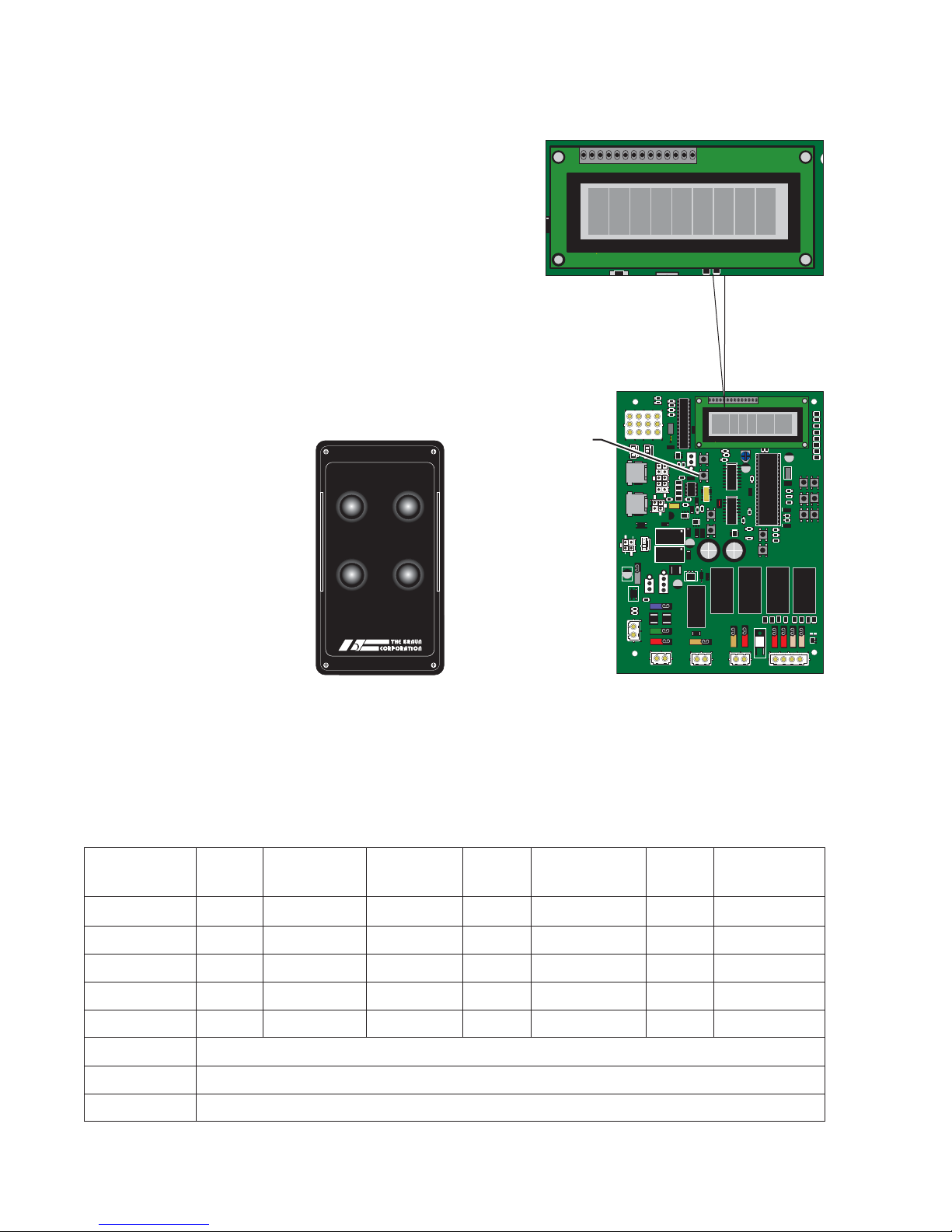
LCD Diagnostic Codes
2
C
To change the LCD display from cycle count to diagnostic
mode, press the “diag” button on the control board (see
illustration at right). When finished, press button again to
return to cycle count mode. When all of the harnesses
are correctly connected to the control board, the values
shown in the chart below will display when the corresponding action is taken. “1” will appear to the right of the switch
or sensor name on the LCD module when activated as
shown. If any other value appears on the LCD screen
during the specific diagnostic procedure, verify that the
correct harness is properly connected to both the control
board and the associated lift harness. Repeat the harness
diagnostic procedure. If an incorrect value is still present
after checking the harness and connections, contact The
Braun Corporation Product Support Department.
All basic functions (UP,
DOWN, STOW and
DOOR) should show a
value of 1 when activated
via a controlled input
(Hand-held Pendant,
Magnetic, Remote Entry
or 3rd Station Controls).
DOOR
STOW
DOWN UP
cycle
diag Button
OBAR S 1
R31
R39
102
R13
R5
243R
R20
C
D
A
B
R19
R18
Lift Devices
K
L
U14
JIH
G
D/S
U/D
C7
321
321
J1
J2
6H23EM
HAND-1
R28
6H23EM
103
HAND-2
U18
Magnetic
C9
V104
INLK-1
U21
OH
RL11
4 3 2 1
321
RL10
Operator
Door
IN
MAT
VR3
FS11
C16
35A
220
5Q6
IN L H
U20
R25
102
FS1
R43
1802
R41
1002
GND
VR2
VR1
PWR-IN
FS2
12V-B
FS8
LIGHT
U16
103
103
103
103
V104
8.00M
C6
V104
U15
cycle
B LIGHT A
103
103
Remote
R1
R16
R26
103
C105
U12
C14
D23
D24
D25
C15
102
V104
D26
R33
103
R11
R37
C5
R36
106 E
330
C8
103
V104
103
U7
U17
D13
D10D11
C22
6C5
100
VHA
D12
U19
R34
C12
5Q6
220
35A
RL9
D9
FS7
LIGHT
W
102
102
OB AR S 1
R31
diag
U5
SOMC1601
CLOSECLOSE
OPEN
C10
V104
C13
RL4
ALARM
ALARM
W
102
102
CONTRAST
102
102
R29
103
U3
R27
CHA
220
6C5
C21
R32
102
V104
U2
C1
ZD3
R38
102
R42
102
R9
103
50# CAL
SW1
R10
103
U22
103
GROUND LVL
O_BAR
SW2
C11
RL2
RL3
D21
D19
D18
FS10
FS9
MP916
0.010Ω
.5% R
FS5
R40
PUMP
VALVE
B_DN
R4
R2
R1
103
R6
103
R7
D20
D7
D8
D5
D6
D3
D4
D
D7
D8
D5
D6
D3
D4
D2 D1
C20
CHA
220
6C5
U8
8.00M
L_UP
L_DN
C4
V104
R15
102
R14
B_DN
B_UP
103
R8
103
C3
V104
L_IN
L_OUT
103
103
NUVL CONTROLLER REV-3.1-1
The Braun Corporation
C2
V104
RL1
D16
D17
D15
D14
R3
U9
FS6
FS4
FS3
L_IN
L_OUT
B_UP
Hand-held Pendant
LCD Display Moving Out
STLV SW 1 1
Stowed
Of Cassette
Moving Up
From Stow
At Floor
Level
Moving Down
From Stow
NUVL Control Board
Ground
Level
Ground Level
OB Out
LOUT SW 1
FOUT SW 1 1 1 1 1
FLV SW 1
OBAR SW 1 1 1 1 1 1
MAT SW = 1 when mat is activated.
DO SW = 1 when door is full open or pin 3 and pin 4 are jumpered.
*IBAR SW = 1 when inboard locator is activated
*(NUVL855C only)
Page 6
Floor Level and Inboard Locator Adjustments
Achieving proper floor level
positioning of the platform and
inboard locator requires a combination of Floor Level switch
adjustment and inboard locator
adjustment. Both are factory set
but must be inspected during
installation procedures (will vary
per vehicle application).
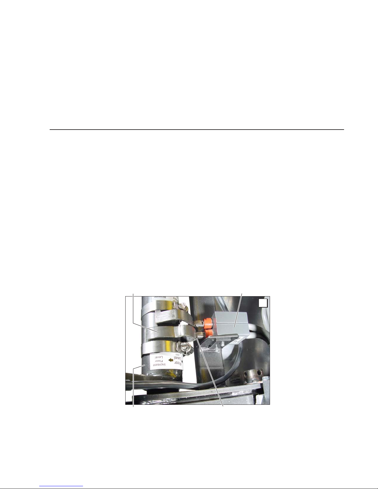
Floor Level Switch Adjustment
Adjust the Floor Level switch
first! (before adjusting the inboard
locator)!
The Floor Level switch stops upward travel of the platform during
the Up function (activated by the
torque tube-mounted Floor Level
cam).
Position the bottom of the lift plat-
Ensure the lift is positioned and
secured as specified on Quick
Reference Installation Sheet (supplied with lift) panels 1 and 2. Ad-
just the Floor Level switch first
(detailed below). Then, adjust
the inboard locator as detailed
in Inboard Locator Adjustment
Instructions (adjust only if neces-
form 1" above floor level (thresh-
old mat) using the manual op
eration system. Do not operate
the lift with the electric pump during adjustment procedures.
Loosen the clamp securing the
torque tube-mounted Floor Level
cam. Rotate the cam until the
Floor Level switch is activated
(cam depresses switch).
sary). The inboard locator must
rest properly on the vehicle floor
for wheelchair entry and exit.
Note: Check the floor level posi-
tion of the platform and the inboard locator after powering the
pump. Hydraulic pressure may affect platform height slightly. Fine
tuning adjustment (tweaking) of
the Floor Level switch may be
required.
Floor Level Cam
Torque Tube
Floor Level Switch
A
Cam depressing switch.
Page 7
Floor Level and Inboard Locator Adjustments
CAUTION
Inboard Locator Adjustment
Do not adjust
inboard locator linkage rod
Do not adjust inboard locator linkage rod. Linkage
rod adjustment may
result in lift damage.
at this time!
Linkage rod
adjustment is not
required unless
extra usable
platform length
is needed. If
the angle of the inboard locator (when in the
vertical position) restricts the usable platform
length for the wheelchair passenger, adjustment of the linkage rod will change the angle.
With the platform at ground level and the
inboard locator in the vertical position, there
should be a minimum of 1” clearance between
the inboard locator and torque tube.
Adjust the inboard locator as detailed in the
following procedures. Then, adjust the linkage
rod as detailed on page 9 (only if necessary).
1. Raise the lift platform fully (floor level) using the manual operation system (Manual
Operating Instructions detailed on Quick
Reference Installation Sheet). If the inboard
locator rests properly on the floor, do not ad-
just the inboard locator. Lower the platform
to ground level. If the angle of the inboard
locator (when in the vertical position), does
not restrict the usable platform length for the
wheelchair passenger, disregard inboard
locator adjustment procedures. See Photo H
on page 9. Refer to the following procedures
if adjustment is required.
Inboard Locator
Linkage Rod
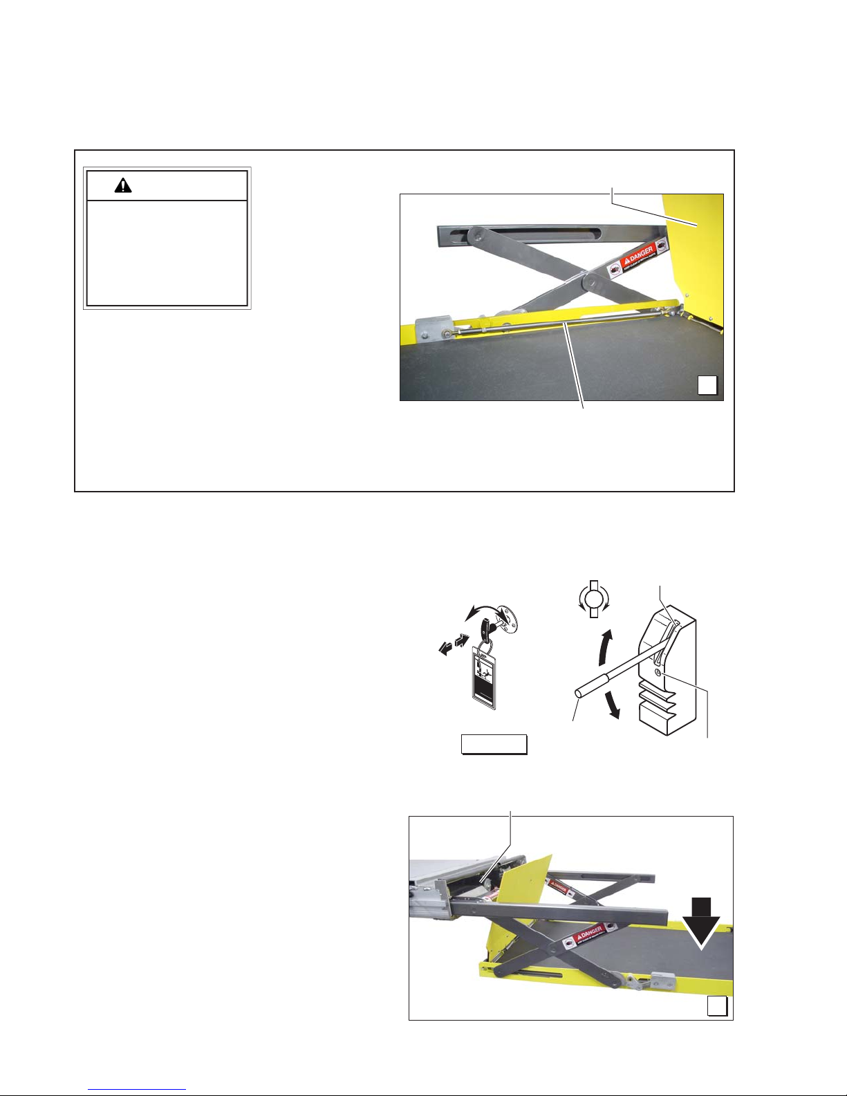
Manual Operation Systems
T-Handle
Release
Cable
W
A
R
NI
N
G
Push T-handle in fully
manually move platfo
and out to engage platfo
lock before driving
Failure to lock platform may
and
result in unintended platform
rm in
deployment. Unintended
rm
veh
platform deployment
icle.
result in serious bodily injury
and/or property dam
may
Do not remove!
ag
e.
81823
Figure A
N
E
P
O
Pump
Handle
VALV E
Stow Level
B
Hand
Pump
C
L
O
S
E
Val ve
2. Position the lift platform below
stow level using the manual op-
eration system. See Photo C.
Lowering the platform will allow access to the cam bolt
securement nut. See Photo E.
Page 8
Platform
below
Stow
Level
C

Floor Level and Inboard Locator Adjustments
Inboard Locator Adjustment
3. Remove the 1/4" lock nut se-
curing the lifting arm cam bolt.
See Photos D and E. Do not
remove the bolt.
Raise the platform fully (floor
level) using the manual op-
eration system.
Remove the cam securement
bolt (lift inboard locator to relieve pressure on bolt).
Allow the inboard locator to rest
on the floor.
Rotate the cam so the cam follower bearing engages the cam
notch (saddle). See Photos F
and G.
Reinstall the cam securement
bolt in one of the three lifting
arm holes that best lines up
with one of the nine holes in the
cam. See Photos F and G.
D
Cam Bolt
1/4" Lock Nut
Reposition the securement bolt
lock nut. Note: Lowering the
platform will allow access to
cam bolt. Tighten securely.
Cam Notch (Saddle)
e
t
C
a
t
o
R
a
m
F
Lifting Arm
(3 available holes)
Slider Block
Rocker
Cam
(9 available holes)
E
Cam Notch (Saddle)
Engaging
Cam Follower Bearing
e
t
C
a
t
o
R
a
m
G
Page 9
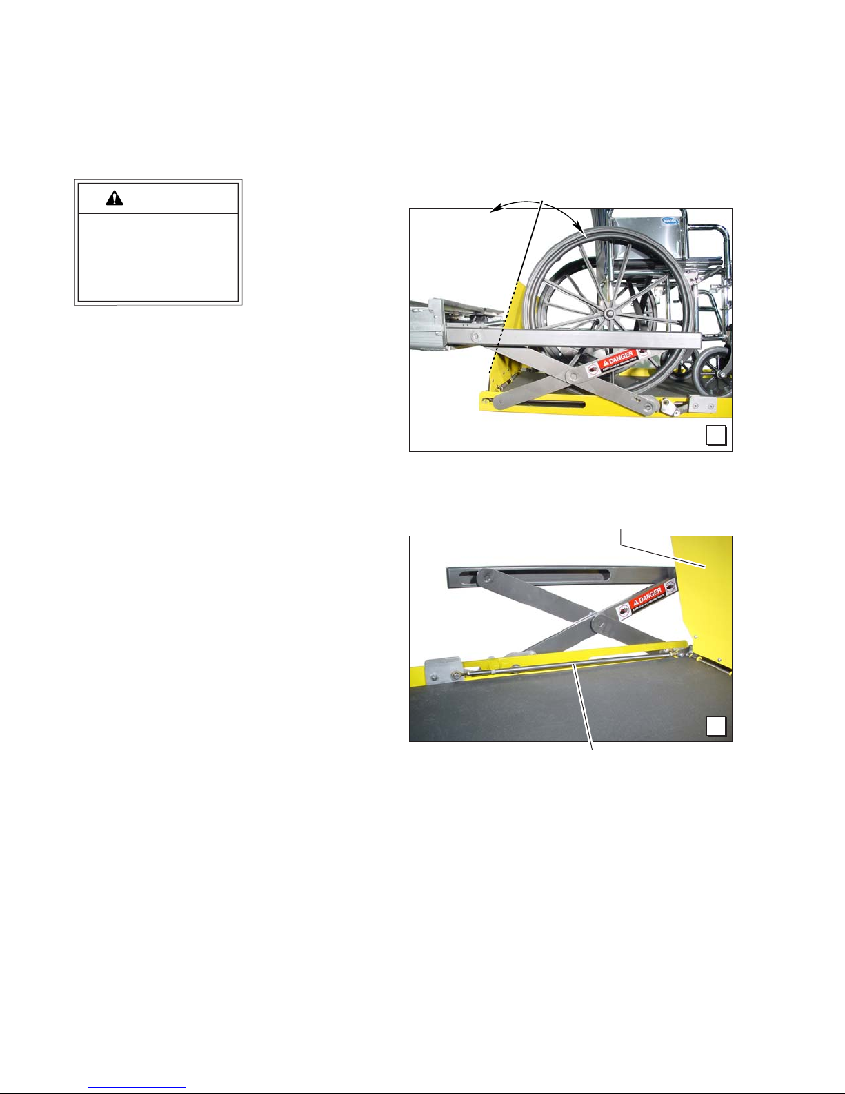
CAUTION
Floor Level and Inboard Locator Adjustments
Inboard Locator Linkage Rod Adjustment
Do not adjust the
inboard locator
linkage rod un-
Improper inboard
locator linkage rod
adjustment may
result in lift damage.
the vertical position) restricts the usable platform
length for the wheelchair passenger, adjustment
of the linkage rod will change the angle.
Adjust the inboard locator as detailed in the
previous procedures. Then, adjust the linkage
rod as detailed (only if necessary). If the link-
age rod is adjusted too long or too short, it will
exceed the travel of the slider block resulting in
damage to the cam follower bearing, the cam
and/or other components.
less extra usable
platform length
is needed. See
Photo H. If the angle of the inboard
locator (when in
Linkage rod adjustment affects angle
of inboard locator (vertical position).
H
Inboard Locator
1. Position the lift platform below stow level
using the manual operation system. Do
not operate the lift with the electric pump
during adjustment procedures.
2. Loosen the jam nuts at each end. Adjust
rod length as needed. Minimize adjustment. Carefully check the inboard locator
angle and operation using the manual
operation system. Ensure the rod has not
been over adjusted resulting in pressure on
components (damage will result). Tighten
the linkage rod jam nuts.
I
Linkage Rod
Page 10
 Loading...