

Page 1
Operator's/Installation/Service Manual
Braun
Braun
Commercial
RA500 Transit Ramp
RA500 Transit Ramp
for
Low-Floor Transit Vehicles
"Providing Access to the World"
International Corporate Hdqrs: P.O. Box 310 Winamac, IN 46996 USA
1-800-THE LIFT® (574) 946-6153 FAX: (574) 946-4670
A
RNING
W
Man
ual
®
®
Read manual
before operating,
installing or
servicing ramp.
Failure to do so
may result in
serious bodily
injury and/or
property damage.
Braun RA500 Transit Ramp
Braun RA500 Transit Ramp
32848 Rev. A
August 2006
Page 2

Congratulations
We at The Braun Corporation wish to express our fullest appreciation
on your new purchase.
With you in mind, our skilled craftsmen have designed and assembled
the finest ramp available.
This manual includes operating instructions, installation instructions,
servicing instructions and instructions for troubleshooting, if needed.
Braun ramps are built for dependability and will provide years of service
and mobility independence, as long as the ramp is installed and maintained as
specified, and the ramp is operated by an instructed person.
THE BRAUN CORPORATION
Ralph W. Braun
Chief Executive Officer
Sincerely,
Page 3

CONTENTS
Ramp Terminology
Ramp Terminology Illustration .................................... 2
Ramp Components Terminology Illustration ............. 3
Introduction .................................................................... 4
Ramp Components ........................................................ 5
Ramp Actions and Functions ....................................... 5
Ramp Operation
Ramp Operation Safety
Safety Symbols ......................................................... 6
Ramp Operation Safety Precautions ..................... 6, 7
Operation Notes and Details
Ramp Access Doors and Interlocks ........................... 8
Operation Procedure Review ..................................... 9
Preventive Maintenance............................................. 9
Maintenance and Lubrication
Lubrication Diagram ................................................... 30
Maintenance and Lubrication Schedule ............. 31, 32
Systems Descriptions
Electronic Controller Calibration .......................... 33-35
Electrical (Microswitches) .................................... 36, 37
Troubleshooting
Troubleshooting Diagnosis Chart ....................... 38, 39
Electrical Schematic .........................................41B, 42B
Wiring Diagram ........................................................... 43
Repair Parts
Ramp Power Operation ............................................... 10
Power Ramp Safety ......................................................11
Ramp Manual Operation ....................................... 12, 13
Ramp Passenger Safety........................................ 14, 15
Ramp Installation
Installation / Service Safety
Safety Symbols ....................................................... 16
Installation / Service Safety Precautions ........... 16, 17
Installation Requirements
Installation Requirements......................................... 18
Chassis Requirements ............................................. 18
Door Opening ........................................................... 18
Obstructions ............................................................. 18
Installation Illustrations ......................................... 19-27
Electrical Connections .......................................... 28, 29
Repair Parts List .......................................................... 40
Exploded View (Fold Out) ................................41A, 42A
Daily Preventive Maintenance Schedule ................ 44
Battery / Ground Connections ................................... 28
Page 1
Page 4
RAMP TERMINOLOGY
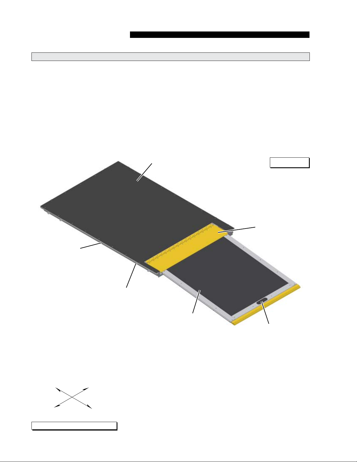
Ramp Terminology Illustration
Refer to the Figure A below and Figure B on page 3
for identication of components and clarication of
direction terminology. Details regarding terminology,
direction and components are provided on pages 4
and 5.
Sub oor
(Fixed)
Figure A
Pan Weldment
IN
Threshold Plate
Mounting Tab
(Qyt 10)
Ramp
Hand Hold
RIGHT
LEFT
As viewed from outside the vehicle
Page 2
OUT
Page 5
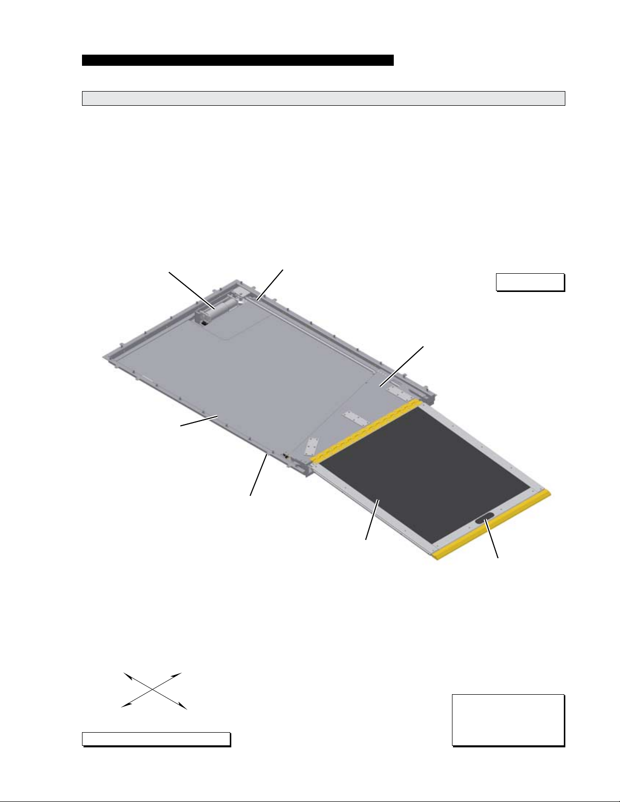
Ramp Components Terminology Illustration
RAMP TERMINOLOGY
Electric Motor
Pan Weldment
Chain Drive
Figure B
Carrier Plate
Mounting Tab
(Qyt 10)
Ramp
IN
LEFT
As viewed from outside the vehicle
RIGHT
OUT
Hand Hold
Note: The sub oor and
transition threshold plate
are removed from this
illustration.
Page 3
Page 6

RAMP TERMINOLOGY
Introduction
The Braun RA500 In-Floor Ramp
(to be referred to as RA500
throughout this manual) is de-
signed for use in low-oor transit
vehicles. The RA500 provides
vehicle access to people with
disabilities (wheelchair passengers or standees using other type
mobility aids).
The self-contained “drop-in” electric unit requires no pre-assembly.
The electrical components are
internal and easily accessible.
The RA500 features a 32” wide
ramp in a 38” wide package. A
“oor pocket” built into the chassis/oor system allows for simple
installation (dimensional require-
ments specied in the Installation
section).
The RA500 is specically designed to be operated by an
attendant. The ramp is controlled
by either a “one-touch control” or
a “press and hold control”.
The RA500 provides fully automatic operation of ramp functions.
The electric system is controlled
by a electronic controller board
which activates an electric motor
in opposite directions for deploy
and stow functions (powering a
chain drive system).
Obstruction sensing is a standard
feature with the RA500 ramp.
The RA500 also has an optional
weight sensitive pad on the ramp
platform. The ramp will not
operate with 15 kilograms on the
platform when equipped with the
weight sensitive pad.
Instructions are provided for
manual operation of the ramp
in event of power or equipment
failure. See Manual Override for
further details.
Read and become familiar with
all operation safety precautions,
pre-operation notes and details,
operating instructions and manual
operating instructions before attempting operation.
Terminology: Become familiar
with the terminology that will be
used throughout this manual.
Become familiar with the iden-
tication of RA500 components
and their functions. Contact your
sales representative or call The
Braun Corporation at 1-800-THE
LIFT® if any of this information is
not fully understood.
Direction: The terms “left”,
“right”, “in” and “out” will be used
throughout this manual to indicate
direction (as viewed from the outside of the vehicle looking directly
at the ramp). Refer to the Termi-
nology Illustrations for clarication
of direction terms.
Page 4
Page 7

Ramp Components
RAMP TERMINOLOGY
Refer to the Terminology Illustrations on pages 2 and 3.
Control Box (Electronic Controller): The remote mounted
control box provides the logic to
manage the inputs in order to
produce the desired outputs in
terms of ramp function and performance. In general terms the
control box is commonly referred
to as the “controller”.
Ramp Actions and Functions
Extend: Extend is the action of
the platform moving out of the
pan weldment (housing).
Retract: Retract is the action of
the platform moving in to the pan
weldment (housing).
Deploy: Deploy is the action of
the ramp assembly extending to
ground level when the DEPLOY
(OUT) switch is activated.
Stow: Stow is the action of the
ramp assembly retracting inward
to the stowed position when the
STOW (IN) switch is activated.
Note: the one touch controller activates both the stow and
deploy functions, dependant upon
the state of the RA500.
Pan Weldment (Housing):
The pan is the aluminum (casing)
mounted in the vehicle oor system which contains the electrical
components that power the ramp
electrical systems. The xed
sub-oor cover protects the com-
ponents from above. The cover
is easily removed for access to
drive components. The sub-oor
provides an antiskid surface for
entry and exit when the ramp
is deployed. The RA500 ramp
stows into the sub oor
Stowed Position: Stowed
position is achieved when the
ramp platform assembly is fully
retracted (resting fully in the pan
weldment).
Manual Override: Manual
operation is achieved through
the use of a mechanical release.
Simply pull the release and use
the hand hold provided on the
ramp platform to manually deploy
or stow the ramp. Minimal physical effort is required to stow and
deploy the ramp platform. Slow
steady motion results in the least
resistance and easy operation.
See pages 12 and 13 for detailed
manual release procedure.
providing an unobstructed antiskid surface for entry and exit
when the ramp is not in use.
Ramp Platform: The ramp
platform is the aluminum ramp
section assembly featuring a full
antiskid surface.
Chain Drive Assembly: The
electric motor driven chain drive
deploys and stows the ramp platform assembly.
Obstruction Sensing: An obstruction sensing feature is standard with the RA500 ramp. The
controller monitors the instantaneous movement of the electric
motor, and calculates a “real time”
running average of the current. It
then compares the programmed
peak (maximum vs. instantaneous) and delta (instantaneous
minus running average) limits to
determine if an obstruction has
been encountered.
Weight Sensing Pad (optional):
The platform can be equipped
with a weight sensing pad. This
optional feature will cause the
ramp not to operate in the event
that 15 kilograms or more is on
the ramp platform.
Page 5
Page 8
RAMP OPERATION
W
A
RNING
W
A
RNING
W
A
RNING
W
A
RNING
W
A
RNING
W
A
RNING
W
A
RNING
W
A
RNING
W
A
RNING
W
A
RNING
CAUTION
CAUTION
CAUTION
CAUTION
W
A
RNING
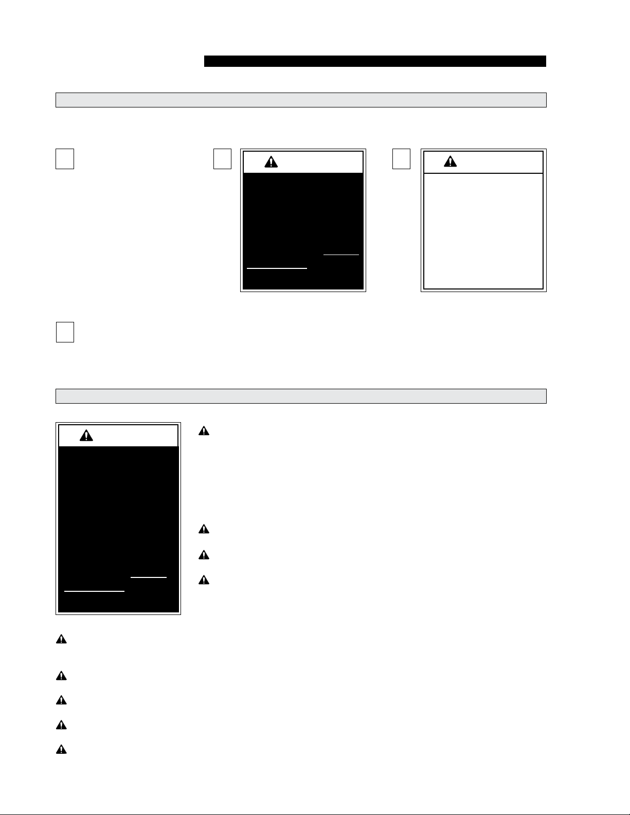
Safety Symbols
SAFETY FIRST! Know That....
All information contained
A
in this manual and
supplements (if included), is provided for your safety. Familiarity
with proper operation instructions
as well as proper maintenance
procedures are necessary to ensure safe, trouble free operation.
Safety precautions are provided
to identify potentially hazardous
situations and provide instruction
on how to avoid them.
Note: Additional information provided to help clarify or detail a specic subject.
D
These symbols will appear throughout this manual. Recognize the seriousness of this information.
Ramp Operation Safety Precautions
If the ramp operating
instructions, manual
operating instructions
and/or ramp operation
safety precautions are
not fully understood,
contact The Braun
Corporation immediately. Failure to do so
may result in serious
bodily injury and/or
property damage.
B
This symbol indicates
important safety
information regarding
a potentially hazardous situation that
could result in serious
bodily injury and/or
property damage.
Read manual and supplement(s) before operating ramp.
Read and become familiar with all safety precautions, preoperation notes and details, operating instructions and
manual operating instructions before operating the ramp.
Note: All transit agency personnel (drivers and ramp attendants) must read and become familiar with the contents of this manual and supplement(s) before operation.
Load and unload on level surface only.
Engage vehicle parking brake before operating ramp.
Provide adequate clearance outside the vehicle to accommodate the ramp before opening ramp door(s) or operating ramp.
C
This symbol indicates
important information regarding how to
avoid a hazardous situation that
could result in minor
personal injury or
property damage.
Page 6
Inspect ramp before operation. Do not operate ramp if you suspect ramp damage, wear
or any abnormal condition.
Keep operator and bystanders clear of area in which the ramp operates.
Load and unload clear of vehicular trafc.
Open ramp door(s) fully and secure before operating ramp.
Do not overload or abuse. The rated capacity is 300 kilograms (660 pounds).
Page 9

W
A
RNING
Ramp Operation Safety Precautions (continued)
W
A
RNING
W
A
RNING
W
A
RNING
W
A
RNING
W
A
RNING
W
A
RNING
W
A
RNING
W
A
RNING
W
A
RNING
W
A
RNING
W
A
RNING
W
A
RNING
W
A
RNING
W
A
RNING
Do not activate control switch(es) when anyone is near the area in which ramp operates.
It is the responsibility of the attendant to oversee and assist ramp passengers.
Attendants must never operate the vehicle, the ramp or attend to passengers if intoxicated.
Intoxicated passengers should not be allowed to board the vehicle.
Wheelchair passengers must position and secure (buckle, engage, fasten, etc.) the
wheelchair-equipped occupant seat belt before loading onto the ramp.
Be aware of the ramp slope (angle).
Wheelchair passengers should not raise front wheelchair wheels (pull wheelie) when on
the ramp.
The wheelchair must be positioned in the center of the ramp when loading and unloading.
RAMP OPERATION
Keep ramp owner’s manual in ramp-mounted vehicle at all times.
Maintenance and lubrication procedures must be performed as specied in this manual
by authorized (certied) service personnel.
Never modify (alter) a Braun Corporation ramp.
Do not use accessory devices not authorized by The Braun Corporation.
Do not remove any guards or covers.
If the information contained in this manual is not fully understood, contact The Braun
Corporation immediately.
Failure to follow these safety precautions may result in serious bodily injury and/or property damage.
Page 7
Page 10

RAMP OPERATION
Operation Notes and Details
The RA500 ramp provides vehicle
access to people with disabilities
(wheelchair passengers or standees using other type mobility
aids). The commercial oriented
RA500 ramp is operated by the
transit vehicle driver/attendant.
Unless your transit agency has
a published policy stating that
driver/attendants do not aid ramp
passengers, safe entering and
Ramp Access Doors and Interlocks
Attendants must become familiar
with the vehicle ramp access door
system and interlock(s), as well
as the proper operation of the
ramp.
Vehicle ramp access door congurations and operation procedures vary. Ensure the ramp door
is fully open before activating the
ramp (an interlock typically prevents ramp operation unless the
door is fully open). Attendants
and passengers must keep clear
of the area in which the power
door operates. Ensure the path
is clear before closing the door.
Be sure the door is fully closed
before attempting to drive the vehicle (interlocks typically ensure
this).
exiting of ramp passengers is
the responsibility of the driver/
attendant.
As stated in the Ramp Operation
Safety section, all information in
this manual is provided for the
safety of passengers, attendants
and bystanders. Recognize the
seriousness of this information.
Interlocks are required by nearly
all transit authorities. Vehicle
interlocks typically prevent vehicle
motion if the ramp is not stowed.
In some cases, the ramp cannot
be operated if interlock conditions
are not met. Interlock requirements may include: the vehicle
transmission must be engaged in
Park, the parking brake must be
engaged, the ramp access door
must be fully open and/or others.
Multiple interlocks may exist.
Instructions for operation of interlocks and door systems cannot be
addressed in this manual due to
the variety of procedures required
for operating them.
Read and become familiar with
all ramp operation safety precautions, pre-operation notes and
details, operating instructions and
manual operating instructions
before attempting ramp operation procedures or assisting ramp
passengers boarding and exiting
the vehicle.
General instructions for safe
operation of the ramp are provided. Ramp safety and ramp
passenger safety information is
included. It is the responsibil-
ity of the attendant to properly
open and close the ramp access
door(s), to activate interlock(s), to
properly activate the ramp power
functions as well as assist ramp
passengers.
Do not operate the ramp if you
suspect ramp damage, wear or
any abnormal condition. Discontinue use immediately and
contact The Braun Corporation
at 1-800-THE LIFT®. One of our
national Product Support representatives will direct you to an
authorized service technician who
will inspect the ramp.
Page 8
Page 11

W
A
RNING
Operation Procedure Review
RAMP OPERATION
The Braun Corporation recommends that transit agency supervisors and driver/attendants
review the safety precautions and
operation procedures appearing
in this manual with the ramp sales
representative (or vehicle converter) before attempting ramp
operation.
Any questions or concerns can be
answered at that time. Operate
the ramp through all functions to
ensure the proper use and operation is understood.
Transit agency supervisors
should train and educate all
driver/attendants on the proper
use and operation of the vehicle,
door system, interlock(s), ramp
and ramp passenger safety.
The ramp owner’s/service manu-
al must be stored in the rampequipped vehicle at all times.
Read and become
familiar with all ramp
operation safety
precautions, preoperation notes and
details, operating
instructions and
manual operating
instructions prior to
operating the ramp.
If this information is
not fully understood,
contact The Braun
Corporation immediately. Failure to do so
may result in serious
bodily injury and/or
property damage.
Preventive Maintenance:
Maintenance is necessary to
ensure safe and trouble free
operation. General preventive
maintenance consisting of care-
ful inspections and cleaning the
ramp system should be a part of
your transit agency’s daily service
program. Simple inspections
can detect potential operational
problems.
Regular preventive maintenance
will reduce potential operation
downtime and increase the
service life of the ramp, as well
as possibly detecting potential
hazards.
A generic Daily Preventive
Maintenance Schedule is
provided in this manual for your
transit agency’s use. The form
can be tailored to your particular
application.
Exposure to harsh weather, environmental conditions, or heavy
usage may require more frequent
maintenance and lubrication
procedures.
Preventive maintenance visual
inspections do not take the place
of the procedures specied in
the Maintenance and Lubrication
Schedule provided in this manual.
Refer to the Maintenance and
Lubrication section in this manual
for further details.
Page 9
Page 12

RAMP OPERATION
Ramp Power Operation
Ramp Operating Instructions
address the required controller
inputs and the corresponding
ramp functions. Instructions for
customer specic display panels
and interlock options will not be
addressed due to the boundless variations in application and
installation of the ramp. Manual
Operating Instructions are addressed in the event of power or
equipment failure.
Before Operating Ramp: Always park the vehicle on a level
area, away from vehicle trafc.
Place the vehicle transmission
in “Park” and engage the park or
emergency brake.
Customer Interlock: The ramp
controller requires either a ground
(-) or (+) signal be supplied, one
of these signals is required but
not both. This signal interlocks
the ramp functions. If this interlock signal is not present, the
controller will not provide any
outputs necessary to operate the
ramp. If the interlock signal is
lost during ramp operation, the
platform assembly will stop, and
the controller will not function any
further until the interlock signal is
present once again.
Operator Input Switches: The
RA500 Ramp electronic controller
provides fully automatic operation
of all ramp functions. Ramp functions can be performed from any
position the platform assembly
happens to be in at the time the
operator input switch is activated.
The ramp is protected by a standard obstruction sensing feature.
One-Touch Operation: In onetouch mode, the ramp will deploy
if fully stowed. If the ramp is in
any other position the ramp will
stow. The ramp function will continue until the switch is pressed
again (indicating stop immediately), the unit reaches the end of
travel, or a “halt condition” occurs
(see Halt Conditions).
Two-Way Toggle Operation:
In two-way toggle mode, there
are separate switches for deploy and stow functions. One of
the switches must be pressed
and held or locked into position
(continuous input signal required)
for the RA500 ramp to operate. The ramp will move in the
selected direction until the switch
is released (signal interrupted),
the unit reaches the end of the
travel, or a “halt condition” occurs
(details follow).
Halt Conditions: Several conditions can cause a normal sequence to terminate (stop):
• Obstructions (details below)
• Customer Interlock signal lost
(see Customer Interlock)
• Optional platform weight sensing pad senses a load equal to
or greater than 15 kilograms
(details below)
• End of travel reached
Obstructions: The controller
performs obstruction sensing
(see RA500 ramp Terminology:
Obstruction Sensing) on all stow
and deploy movements of the
ramp. The selected obstruction
response mode congured in
the controller during installation,
either immediately stops the present movement when obstructed,
or stops and then reverses
movement for 1 second. Once an
obstruction has halted the ramp,
the controller automatically resets
and awaits operator input for
further operation.
Weight Sensing Pad (optional):
The platform can be equipped
with a weight sensing pad. This
optional feature will cause the
ramp not to operate in the event
that 15 kilograms or more is on
the ramp platform.
Page 10
Page 13
W
A
RNING
Power Ramp Safety
W
A
RNING
Keep clear of
area in which
ramp operates.
CAUTION
CAUTION
CAUTION
RAMP OPERATION
Be certain there is adequate
clearance outside the vehicle before deploying the power ramp.
The ramp operator (attendant)
and bystanders must keep clear
of the area in which the ramp
operates and clear of all moving
parts. Attendants must ensure
that passengers keep clear of the
area in which the ramp operates.
Do not attempt to grip or hold the
ramp.
If you are an attendant operating
the ramp, it is your responsibility to oversee and/or assist in
performing safe passenger loading and unloading procedures.
Observe your passengers at all
times when they are entering and
exiting the vehicle. Attendants
must be aware of any special
needs and/or procedures required
for safe transport of wheelchair
passengers.
Do not attempt to load or unload
a passenger in a wheelchair or
other apparatus that does not t
on the ramp. Do not exceed the
300 kilograms (660 pound) load
capacity of the ramp. Passengers should enter and exit one at
a time. The attendant should not
board the ramp with the passenger except when assistance is
required and the load capacity is
not exceeded. Always return the
ramp to the stowed position when
not in use.
Provide adequate
clearance outside
of vehicle to accommodate ramp.
Failure to do so may
result in serious
bodily injury and/or
property damage.
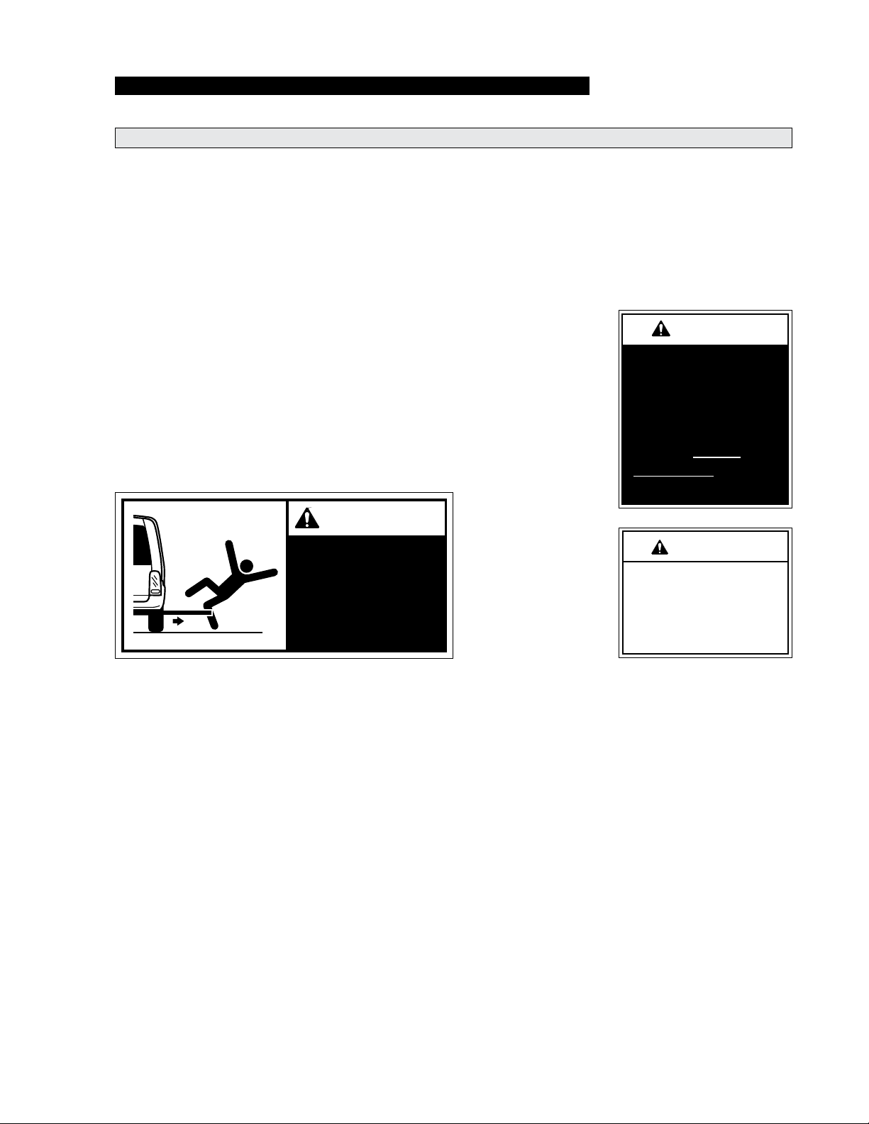
Allow ramp to deploy
fully before boarding.
Failure to do so may
result in damage.
Page 11
Page 14
RAMP OPERATION
TO
LOCK
TURN
TO
LOCK
TURN
TO
LOCK
TURN
TO
LOCK
TURN
TO
LOCK
TURN
TO
LOCK
TURN
W
A
RNING
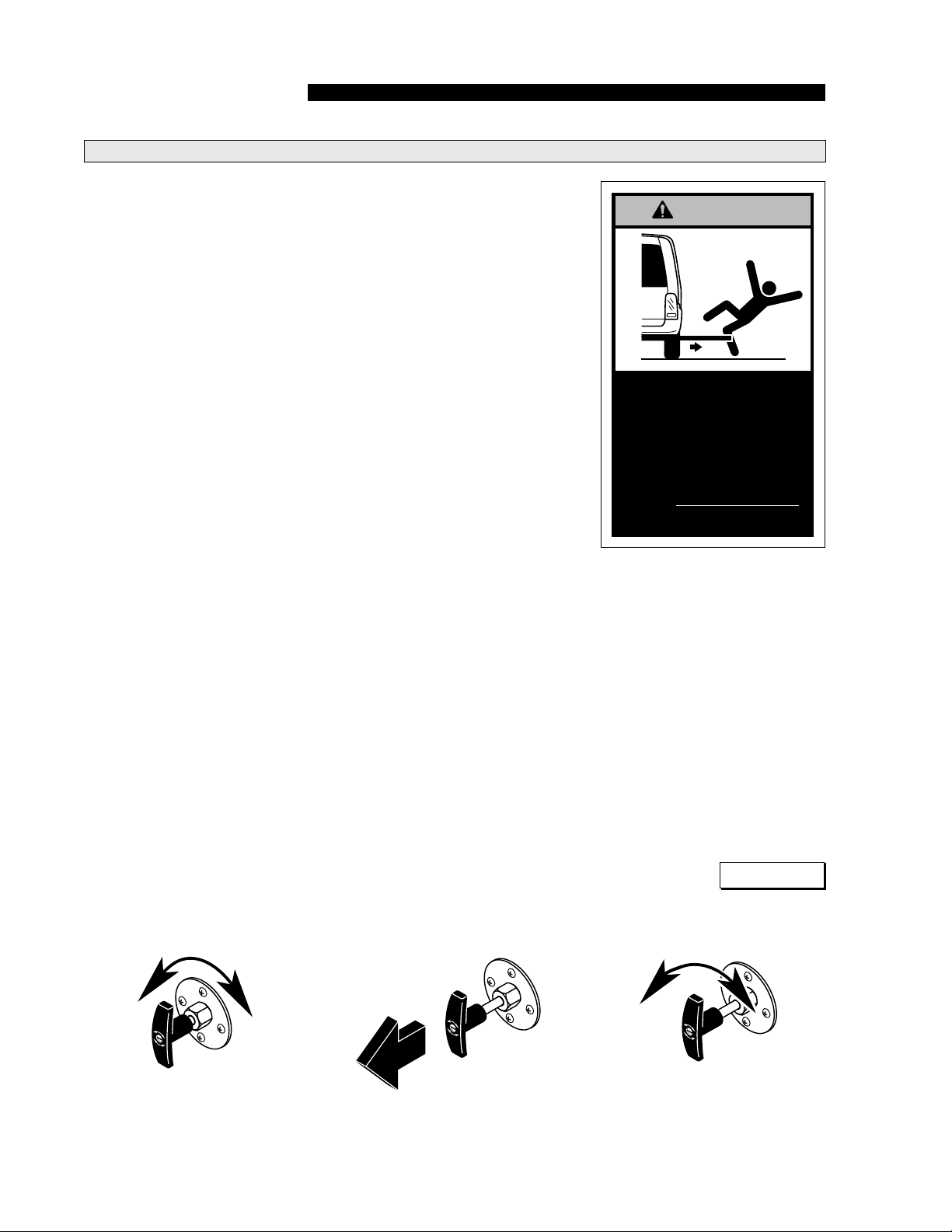
Push T-handle in fully and
manually move platform in
and out to engage platform
lock before driving vehicle.
Failure to lock platform may
result in unintended platform
deployment. Unintended
platform deployment may
result in serious bodily injury
and/or property damage.
Ramp Manual Operation
If you experience power or equipment failure, the ramp can be
manually stowed and deployed.
The RA500 must be manually
operated by an attendant.
The RA500 is equipped with a
cable-activated manual release
system and a oval-shaped hand
hold slot in the platform for
manual operation (see Figure C
and E).
The safety precautions addressed
in the Ramp Power Operation
section apply to manual operation of the ramp also. Read and
become familiar with all ramp
safety precautions.
Cable-Activated Manual Release System: A cable activated
manual release system disengag-
es (unlocks) the ramp platform
assembly drive chain to allow the
platform to be manually extended
or retracted as required. A Thandle is provided on the release
cable for activation of the manual
release system (details follow).
After manually extending or
retracting the platform assembly,
it is extremely important that the
cable-activated manual release is
positively re-engaged to secure
(lock) the platform assembly
before loading a passenger or
continuing vehicle use (details
provided). Failure to re-engage
and secure the platform may
result in unintended ramp
movement, which may result
in serious bodily injury and/or
property damage.
To Manually Extend or Retract Ramp:
1. Turn (loosen) the manual
release “T” handle 90°.
2. Pull the “T” handle fully outward (3" to 4").
3. Turn (tighten) the “T” handle
90° to secure handle in the disengaged (unlocked) position.
Page 12
Step 1 Step 2 Step 3
4. Verify mechanism is disengaged (unlocked).
5. Carefully move the platform
in or out to desired location
using the platform Hand Hold
(see Figure E).
Note: Minimal physical effort is
required to manually operate the
ramp. Slow steady motion results
in the least resistance and easy
operation. The faster you attempt
to manually operate the ramp, the
greater the resistance.
Figure C
Page 15
TO
LOCK
TURN
TO
LOCK
TURN
TO
LOCK
TURN
TO
LOCK
TURN
TO
LOCK
TURN
TO
LOCK
TURN
TO
LOCK
TURN
TO
LOCK
TURN
Ramp Manual Operation (continued)
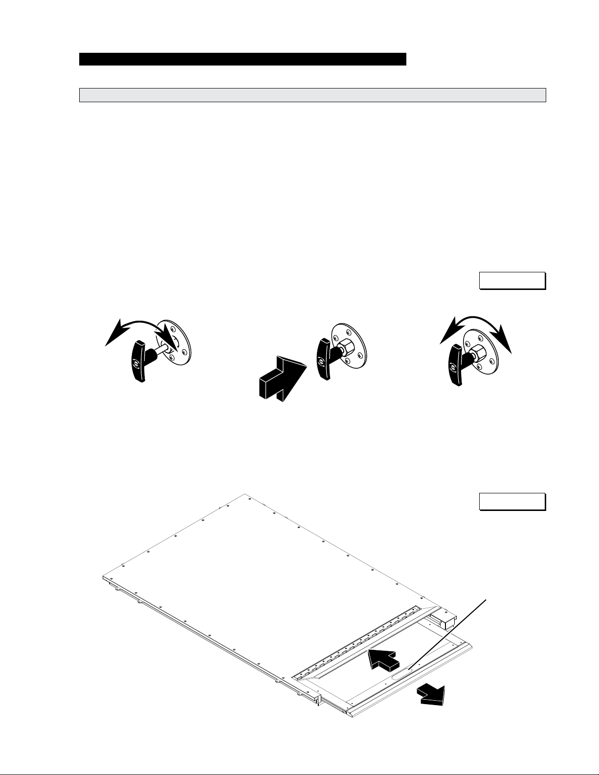
To Reengage Carriage Assembly to Drive Chain:
RAMP OPERATION
1. Position the ramp platform
manually so that only 15 cm
is extended out of the cassette.
2. Turn (loosen) the manual
release “T” handle 90°.
3. Push the “T” handle fully
inward until handle contacts
shaft shoulder (3" to 4").
4. Grasp the platform Hand Hold
and move the platform slightly
outward until platform locks
into position (secured by reengaging the carriage assembly with the drive chain).
5. Turn (tighten) the “T” handle
90° to secure handle in the
engaged (locked) position.
6. Verify mechanism is reengaged (locked). Pull on the
Hand Hold to ensure no
movement occurs.
7. Stow the remaining portion
of the platform by using the
electrical system.
Figure D
Step 2 Step 3 Step 5
Figure E
Hand Hold
Page 13
Page 16

RAMP OPERATION
W
A
RNING
W
A
RNING
Keep clear of
area in which
ramp operates.
W
A
RNING
Be aware of
ramp slope.
52217
Ramp Passenger Safety
Unless your transit agency has
a published policy stating that
driver/attendants do not aid ramp
(disabled) passengers, it is the
responsibility of the driver/attendant to ensure that ramp
passengers enter and exit the
vehicle on the ramp in the safest manner.
ADA requirements state that transit drivers/attendants must assist
with attaching and removing
wheelchair and occupant restraint
belts.
Ramp passengers (wheelchair
passengers and standees), and
attendants must use common
sense and good judgment regarding ramp safety. Each wheelchair
passenger (or standee) has a
unique set of physical abilities
combined with the physical characteristics of his or her wheelchair
(or other mobility aid) that dictate
the method in which he or she will
enter and exit the vehicle.
Wheelchair attendants should be
instructed on any special needs
and/or procedures required for
safe transport of wheelchair passengers. Follow all safety instructions regarding torso restraints,
Position and fasten
the wheelchairequipped occupant
seat belt before
loading onto the
wheelchair ramp.
Failure to do so may
result in serious
bodily injury and/or
property damage.
stability, balance, weight distribution and use of attendants as
specied in the owner’s manual
supplied with the passenger’s
wheelchair (or other mobility aid).
Wheelchair passengers must
determine, establish and practice
ramp boarding and exiting procedures under the direction of the
their personal health care professional and wheelchair representative. Those procedures should be
conveyed to the ramp attendant.
Know your passengers abilities
and needs for optimum safety.
Attendants must never operate
the vehicle, the ramp or assist
passengers if intoxicated. Intoxicated passengers should not
be allowed to board or exit the
vehicle.
Passengers should be positioned
in the center of the ramp at all
times. Attendants and ramp passengers must be able to clearly
view the ramp whenever boarding
and exiting the vehicle. Observe
your passengers at all times when
they are entering and exiting the
vehicle.
Wheelchair-Equipped Occupant
Seat Belts: Wheelchair passen-
gers should position and buckle
their wheelchair-equipped seat
belt (torso restraint), as specied
by the manufacturer, before loading onto a wheelchair ramp.
Different types of disabilities
require different types of wheelchairs and different types of
wheelchair-equipped occupant
restraint belt systems (torso restraint). It is the responsibility of
the wheelchair passenger to have
his or her wheelchair equipped
with an occupant restraint (seat
belt) under the direction of their
health care professional.
Stabilizing Wheelchairs: Powered and manual wheelchairs
are designed to remain upright
and stable during normal operation. All activities which involve
movement in a wheelchair have
an effect on the combined center
of gravity of the occupant and
wheelchair. Be aware of the ramp
slope (angle). The slope of the
ramp has a direct effect on the
center of gravity. The wheelchair
passenger’s center of gravity and
their ability to maintain stability
and balance must be kept in mind
by the wheelchair passenger and
the attendant.
The aid of an attendant stabilizing
the wheelchair is recommended
for optimum safety. Wheelchair
passengers who are unable to
maintain stability and balance
should not board a ramp without
assistance. Counterbalance
devices (anti-tippers) may be
available from the wheelchair representative to enhance stability
and balance.
Page 14
Page 17

Ramp Passenger Safety
RAMP OPERATION
Wheelchairs should be operated
at a slow and constant speed
when on the ramp. Wheelchairs
should not accelerate suddenly
when on the ramp. Wheelchair
passengers should not raise the
front wheelchair wheels (pull
wheelie) when on the ramp.
Wheelchair passengers who
intend to enter and exit the
vehicle without the assistance of
an attendant must determine the
safest and most practical method
and orientation of entering and
exiting based on the physical
characteristics of their personal
wheelchair and his or her physical
capabilities to maintain stability
while the wheelchair is in motion
on the ramp.
Wheelchair Attendants: When
assisting a wheelchair occupant,
remember to use good body mechanics. When the wheelchair is
on the ramp, the attendant must
grasp the push handles (or other)
securely. Detachable wheelchair
parts such as arms or leg rests
must never be used for hand
holds or lifting supports. Doing
so could result in the parts being
inadvertently detached from the
wheelchair resulting in possible
injury to the wheelchair occupant and/or the attendant.
Page 15
Page 18

W
A
RNING
W
A
RNING
CAUTION
CAUTION
CAUTION
CAUTION
W
A
RNING
W
A
RNING
W
A
RNING
W
A
RNING
RAMP INSTALLATION
CAUTION
CAUTION
CAUTION
CAUTION
W
A
RNING
W
A
RNING
W
A
RNING
W
A
RNING
W
A
RNING
Safety Symbols
SAFETY FIRST! Know That....
All information contained
A
in this manual and
supplements (if included), is provided for your safety. Familiarity
with proper operation instructions
as well as proper maintenance
procedures are necessary to ensure safe, trouble free operation.
Safety precautions are provided
to identify potentially hazardous
situations and provide instruction
on how to avoid them.
Note: Additional information provided to help clarify or detail a specic subject.
D
These symbols will appear throughout this manual. Recognize the seriousness of this information.
Installation / Service Safety Precautions
B
This symbol indicates
important safety
information regarding
a potentially hazardous situation that
could result in serious
bodily injury and/or
property damage.
Read this manual and supplement(s) before performing installation, operation or service procedures.
C
This symbol indicates
important information regarding how to
avoid a hazardous situation that
could result in minor
personal injury or
property damage.
If installation, maintenance or repair
procedures cannot
be completed exactly as provided in
this manual or if the
instructions are not
fully understood,
contact The Braun
Corporation immediately. Failure to do
so may result in
serious bodily injury
and/or property
damage.
Installation specications and dimensions must be met.
Remove any obstructions within the ramp mounting/operating
area prior to beginning installation procedures.
Do not operate ramp prior to positive securement of the pan.
Check for obstructions such as gas lines, wires, exhaust, etc.
before drilling or cutting during installation procedures.
Route all cables clear of exhaust system, other hot areas,
moving parts, wet areas, etc.
Risk of electrical shock or re! Use extra care when making
electrical connections. Connect and secure as outlined in
Installation Instructions and Wiring Diagrams.
Maintenance and repairs must be performed only by authorized service personnel.
Perform maintenance and lubrication procedures exactly as outlined in the Maintenance
and Lubrication Schedule contained in this manual. Disconnect the power cable at the
battery prior to servicing.
Keep hands, arms and all other body parts clear of moving parts.
Page 16
Page 19

Installation / Service Safety Precautions
W
A
RNING
W
A
RNING
W
A
RNING
W
A
RNING
Never modify (alter) a Braun Corporation ramp.
Replacement parts must be Braun authorized replacements.
Never install screws or fasteners (other than factory equipped).
Failure to follow these safety precautions may result in serious bodily injury and/or property damage.
RAMP INSTALLATION
Page 17
Page 20

W
A
RNING
RAMP INSTALLATION
Installation Requirements
Braun RA500 Ramp must be
installed and serviced by a Braun
authorized service representative who has attended and been
certied by The Braun Corporation Sales and Service School for
Braun Mobility Products.
Chassis Requirements
The Braun RA500 Ramp is
designed for use in low-oor
transit vehicles. A “oor pocket”
(mounting hole) built into the
chassis/oor system allows for
simple installation (accepts “dropin” unit). The Floor Pocket Clear
Opening Dimensions on the
following pages.
An optional RA500 model without
the xed sub oor is available.
When installing this model the
vehicle oor is installed above
the ramp assembly. This model
is designed to be installed above
the frame, but below the vehicle
oor. This model does not have
the xed sub oor on top of the
assembly.
The ramp installer must provide
an appropriate framework in the
applicable location in the vehicle
(aligned center with passenger
door opening). Ramp assembly
mounting hardware and/or bracketry are directly dependant upon
the vehicle chassis and “oor
pocket” conguration (not sup-
plied).
Read and become familiar with
the operating instructions and the
installation instructions contained
in this manual before beginning
installation, operation or service
procedures.
Outboard Support Tube: An
outboard support tube must be
positioned under the outboard
edge of the opening (minimum
40mm x 50mm steel tube). See
Figure F. The recommended
maximum height of the support
tube is 210mm above ground
level.
Kneeling Vehicles: 210mm is
the maximum dimension measured with suspension lowered.
EU: Installations with the support tube positioned higher than
210mm above ground level may
not comply with EU ramp slope
requirements.
Some OEM chassis meet these
specications. The RA500 ramp
was designed to conform to these
specications.
The ramp pan horizontal bor-
der (lip) sets on the oor pocket
perimeter (framework, sub oor,
etc.). The nished ooring can be
cut to conform to the border of the
pan for a ush transition surface
from ramp-to-oor. The nished
ooring can also go over the top
of the ramp if the optional ramp
model with out the xed sub oor
is installed.
Read this manual
before performing
installation, operation
or service procedures.
Failure to do so may
result in serious
bodily injury and/or
property damage.
Door Opening: Open the door(s)
fully and check the clear door
opening width dimension. Specied minimum clear door opening width must be provided
(850mm for 825mm ramp).
Door(s) must open outward.
When closed, the door(s) should
align with and conform to the
outboard edge of the ramp pan
(rubber seal on bottom of door).
Minimum Clear Door Opening
Dimensions are dened as nished door opening, including any
intrusive door jambs, headers,
sills or hinges.
Obstructions: Any intrusive obstructions within the door opening
or the ramp mounting/operating
area (such as seats, molding,
lights, brackets, etc.) must be
removed. Trim or molding that
creates an uneven mounting surface should be removed.
Page 18
Page 21

Ramp Support Structure
Chassis
Chassis
SUPPORT TUBE
Floor Pocket
Frame Work
RAMP INSTALLATION
Outboard Support Tube: Recommended Maximum Height: 210mm above ground level. Kneel-
ing Vehicles (measured with suspension lowered).
EU: Installations with support tube positioned
higher than 210mm above ground level may not
comply with EU ramp slope requirements.
Figure F
Structure: Minimum
40mm x 50mm steel
tubing (or equivalent).
In
Left
As viewed from outside the vehicle
Right
Out
Page 19
Page 22

Chassis
Chassis
Chassis
Chassis
SUPPORT TUBE
1455mm
1005mm
Floor Pocket
Frame Work
RAMP INSTALLATION
"Floor Pocket" Clear Opening Dimensions
Figure G
The ramp must
be supported by a
minimum of three
chasis members.
Page 20
In
Left
As viewed from outside the vehicle
Right
Out
Page 23

Chassis
Chassis
Chassis
Chassis
C
L
Minimum Door Opening Width:
850
mm opening
for 825mm Ramp
C
L
MINIMUM
DOOR OPENING
WIDTH
1455mm
1005mm
Clear Door Opening Width Dimension
RAMP INSTALLATION
Figure H
The ramp platform
must be aligned
with the center of
the door opening.
Door(s) must
open outward.
Page 21
Page 24

Chassis
Chassis
Chassis
Chassis
C
L
Minimum Door Opening Width:
850
mm opening
for 825mm Ramp
C
L
MINIMUM
DOOR OPENING
WIDTH
RAMP INSTALLATION
Installed Ramp - Stowed
Figure J
Ramp positioned in
Stowed RA500
the “oor pocket.”
Page 22
In
Left
As viewed from outside the vehicle
Right
Out
Page 25

Ramp Support Structure for RA500 w/o Fixed Sub oor
Chassis
Chassis
SUPPORT TUBE
RAMP INSTALLATION
Outboard Support Tube: Recommended Maximum Height: 210mm above ground level. Kneel-
ing Vehicles (measured with suspension lowered).
EU: Installations with support tube positioned
higher than 210mm above ground level may not
comply with EU ramp slope requirements.
Figure K
Structure: Minimum
40mm x 50mm steel
tubing (or equivalent).
Page 23
Page 26

RAMP INSTALLATION
Chassis
Chassis
1455mm
1005mm
SUPPORT TUBE
"Floor Pocket" Clear Opening Dimensions for RA500 w/o Fixed Sub oor
Figure L
Page 24
In
Left
As viewed from outside the vehicle
Right
Out
Page 27

Clear Door Opening Width Dimension for RA500 w/o Fixed Sub oor
Chassis
Chassis
C
L
Minimum Door Opening Width:
850mm opening
for 825mm Ramp
C
L
MINIMUM
DOOR OPENING
WIDTH
Chassis
Chassis
SUPPORT TUBE
1455mm
1005mm
SUPPORT TUBE
RAMP INSTALLATION
Figure M
The movable ramp
platform must be
aligned with the
center of the door
opening.
In
Left
As viewed from outside the vehicle
Right
Out
Page 25
Page 28

RAMP INSTALLATION
Chassis
Chassis
Chassis
Chassis
C
L
Minimum Door Opening Width:
850mm opening
for 825mm Ramp
C
L
MINIMUM
DOOR OPENING
WIDTH
Installed Ramp - Stowed RA500 w/o Fixed Sub oor
Figure N
The movable ramp
platform must be
aligned with the
center of the door
opening.
Page 26
Door(s) must
open outward.
Page 29

Installed Ramp - Stowed with Vehicle Floor Installed over Ramp
Chassis
Chassis
Chassis
Chassis
Figure P
RAMP INSTALLATION
Floor should support
upper surface of the
ramp.
In
Left
As viewed from outside the vehicle
Right
Out
Page 27
Page 30

W
A
RNING
W
A
RNING
W
A
RNING
RAMP INSTALLATION
Electrical Connections
The ramp installer provides an
appropriate control switch for the
end user. One-touch operation
using a single "operate" button
(switch) or two-way toggle operation with dedicated switches for
the stow and deploy command
are options.
Battery / Ground Connections
The Positive (+) “battery” lead wire must
be protected by an in-line 25 ampere
fuse or circuit breaker (installer pro-
vided).
Do not connect the power “battery” lead
wire to the battery until all other connections are made.
Installer connections are listed in
the table on the following page.
Strip wires, crimp and install con-
tacts as specied in instructions
supplied with the power connector (Molex 2-pin) and the data
connector (Amp 14-pin).
Figure Q
Cable
Clip
Route cables clear
of exhaust system,
other hot areas and
moving parts. Failure
to do so may result
in serious bodily
injury and/or property
damage.
Secure all cables using cable
ties and/or cable clips (mount
clips with self-tap screws).
Cable
(typical)
Connect the 14-pin data harness plug to
the mating connector on the controller.
Connect the 2-pin Power harness plug to
the mating connector on the controller.
Risk of electrical
shock! Use extra
care when making
electrical connections.
Risk of electrical re!
Use extra care when
making electrical
connections.
Vehicle
Floor
Cable Tie
Vehicle
Floor
Framing
Member
Self-Tap Screw
Carefully connect the power “battery” lead
wire to the Positive (+) battery post.
Chassis Ground Corrosion: When
mounting chassis ground cables, remove
undercoating, dirt, rust, etc. from the framing member around the mounting holes.
Apply a protective coating to mounting
holes to prevent corrosion. Apply grease
to ground cable terminals and mounting
hardware. Failure to do so will void war-
ranty of certain electrical components.
Page 28
Page 31

W
A
RNING
Electrical Connections
RAMP INSTALLATION
The 2 pin power harness connector and the 14-pin data harness
connector are supplied with the
ramp.
Note: Connectors are supplied
only, harnesses are supplied by
ramp installer. The ramp installer
is responsible for vehicle connections.
Terminate the power supply,
ground and ramp data signals as
specied in the legends below.
The Positive (+) “battery” lead
wire must be protected by an
in-line 25 ampere fuse or circuit
breaker (installer provided).
Positive (+) battery
lead wire must be
protected by
installer-provided 25
ampere fuse or
circuit breaker.
Failure to do so may
result in serious
The ramp installer provides an
appropriate momentary contact
bodily injury and/or
property damage.
control switch.
Power Harness with Molex 42816-0212 Connector (installer provided)
Function Pin No. Description Wire Size
Input 1 Battery - 24 Volt with 25 Amp. Protection Device 10 Gauge
Input 2 Ground - Battery 10 Gauge
Wire Maximum Length: 10 Meters
Data Harness with AMP 206044-1 Connector (installer provided)
Function Pin No. Description Wire Size
Output 1 Indicator - Move Out - Normally Open (N.O.) 14 to 18 Gauge
Output 2 Indicator - Alarm - Normally Open (N.O.) 14 to 18 Gauge
Input 3 Switch - Ramp Deploy 14 to 18 Gauge
Input 4 Switch - One Touch 14 to 18 Gauge
Input 5 Indicator - Power Common Fused 14 to 18 Gauge
Output 6 Indicator - Manual Release - Normally Open (N.O.) 14 to 18 Gauge
Input 7 Ramp Enable 14 to 18 Gauge
Output 8 Switch - Common 14 to 18 Gauge
Output 9 Indicator - Full In - Normally Open (N.O.) 14 to 18 Gauge
Input 10 Switch - Ramp Stow 14 to 18 Gauge
Input 11 Switch - Park Brake (LOW) to Operate 14 to 18 Gauge
Output 12 Indicator - Move In - Normally Open (N.O.) 14 to 18 Gauge
Output 13 Indicator - Full Out - Normally Open (N.O.) 14 to 18 Gauge
Input 14 Switch - Park Brake (HIGH) to Operate 14 to 18 Gauge
Notes: Either the One touch
switch or both the Deploy and
Stow switch connections should
be utilized but not both.
The Park Brake switch (either
high or low) and Ramp Enable
are required for ramp to operate.
Ramp Enable requires + Vehicle
See metric to US wire size conversion chart on page 43.
power to operate.
Page 29
Page 32

MAINTENANCE and LUBRICATION
Lubrication Diagram
See the Maintenance/Lubrication Schedule for recommended applications per number of cycles or elapsed time.
Motor
Guide
Rails
LO
Manual
Release CAM
LO
Drive Gear
LG
Drive Chain
LO
Drive Chain / Pulley
LO
Carrier Plate
Wear Strips
DE
Ramp Hinge
LO
Specied (recommended) Available Braun
Lubricant Type Lubricant Amount Part No.
LO - Light Oil
DE - Door-Ease
LG - Light Grease
Light Penetrating Oil LPS2, General Purpose 11 oz.
(30 weight or equivalent) Penetrating Oil Aerosol Can
Stainless Stick Door-Ease 1.68 oz.
Style (tube) Stick (tube)
Light Grease Lubricate 14 oz.
(Multipurpose) Can
15807
15806
15805
Page 30
Page 33

W
A
RNING
Maintenance and Lubrication Introduction
MAINTENANCE and LUBRICATION
Proper maintenance is necessary to ensure safe,
trouble-free operation. Inspecting the ramp for
any wear, damage or other abnormal conditions
should be a part of all transit agencies daily service
program (preventive maintenance). Simple inspections can detect potential problems.
A generic Daily Preventive Maintenance Sched-
ule is provided in this manual for transit agency
use. The form can be tailored to your particular
application. Preventive maintenance visual inspections do not take the place of the procedures speci-
ed in this schedule.
The maintenance and lubrication procedures specied in this schedule must be performed by a Braun
authorized service representative at the scheduled
intervals according to the number of cycles or
elapsed time, whichever comes rst.
RA500 ramps are equipped with hardened pins and
self-lubricating bearings to decrease wear, provide
smooth operation and extend the service life of the
ramp.
Clean the components and the surrounding area
before applying lubricants. LPS2 General Pur-
pose Penetrating Oil is recommended where Light
Oil is called out. Use of improper lubricants can
attract dirt or other contaminants which could result
in wear or damage to the components. Ramp components exposed to contaminants when lowered to
the ground may require extra attention. Specied
lubricants are available from The Braun Corporation
(part numbers provided on page 30).
Recommended Intervals: These intervals are a
general guideline for scheduling maintenance pro-
cedures and will vary
according to ramp use
and conditions. Transit
agencies operating
vehicles equipped with
ramps that are not
monitored by cycles
may choose to have
the ramp system maintained on the same
schedule as the vehicle
(routine maintenance).
Doing so ensures the
ramp is being maintained regularly.
When servicing the ramp at the consecutive recommended intervals, inspection and lubrication proce-
dures specied in the previous sections should be
performed (repeated). All listed inspection, lubrication
and maintenance procedures should be repeated at “8
Weeks or 200 Cycles” intervals following the scheduled
“1 Year or 1250 Cycles” maintenance.
Lifts exposed to severe conditions (weather, environment, contamination, heavy usage, etc.) may require
inspection and maintenance procedures to be per-
formed more often than specied.
Discontinue ramp use immediately if maintenance
and lubrication procedures are not properly performed,
or if there is any sign of wear, damage or improper
operation. Contact your sales representative or call
The Braun Corporation at 1-800-THE LIFT®. One of
our national Product Support representatives will direct
you to an authorized service technician who will inspect
your ramp.
Maintenance and lubrication procedures
must be performed
as specied by an
authorized service
technician.
Failure to do so may
result in serious
bodily injury and/or
property damage.
Maintenance and Lubrication Schedule
Inboard ramp hinge
8 Weeks
Threshold plate hinge
or 200
Cycles
continued
Drive chain (chain, pulleys and guides)
Manual release (cable and mechanism)
Clean and lubricate. Apply Light Oil - See
Lubrication Diagram
Clean and lubricate. Apply Light Oil - See
Lubrication Diagram
Apply Light Oil - See Lubrication Diagram
Apply Light Oil - See Lubrication Diagram
Page 31
Page 34

MAINTENANCE and LUBRICATION
Maintenance and Lubrication Schedule (continued)
continued
Carrier plate wear strips
Clean and lubricate. Apply Door-Ease
8 Weeks
or 200
Cycles
1 Year
or
1250
Cycles
Clean ramp and ramp mounting area (ensure
no debris in area to obstruct stowing )
Inspect ramp for wear, damage or any abnormal condition.
Perform all procedures listed in previous section also
Remove motor cover and clean dirt and other
foreign debris
Remove motor cover and inspect:
• Harness cables, wires, terminals and connections for securement or damage
Drive gear
Motor guide rails
Manual release CAM
Drive chain
Clean and remove debris or obstructions
Correct as needed
Blow out with air compressor
Re secure, replace defective parts or otherwise
correct as needed.
Apply Grease - See Lubrication Diagram
Apply Light Oil - See Lubrication Diagram
Apply Light Oil - See Lubrication Diagram
Apply Light Oil - See Lubrication Diagram
Consecutive
8 Week or
200 Cycle
Intervals
Page 32
Adjust chain tension
Inspect vehicle-to-ramp wiring harness
Mounting
Antiskid
Repeat all previously listed inspection, lubrication and maintenance procedures at 8 week or
200 cycle intervals (or per vehicle maintenance
schedule).
Adjust as needed
Re secure, repair or replace or otherwise correct as needed
Check to see that the ramp is securely anchored to the vehicle and there are no loose
bolts, broken welds, or stress fractures.
Replace decals if worn, missing or illegible.
Replace antiskid if worn or missing.
Page 35

Electronic Controller
SYSTEMS DESCRIPTIONS
Introduction: The following procedure is for calibration of the RA500 Series Controller. Calibrate
the controller only if ramp does not function
properly.
Electronic Controller can be calibrated using a
computer (recommended) or manually using the
onboard Calibrate button and potentiometers.
Computer Calibration Instructions for Controller
Connect the Computer to the Controller:
1. Remove the controller cover. Press the “Calibrate” button and then the “Calibrate Reset”
button to restore factory defaults (see Figure S).
2. Locate J9 (9-pin Port) and connect a serial
cable from J9 to an available COM slot on the
computer.
Establish a connection between the computer
and the controller:
Note: This is done from the computer after the
physical connection has been made.
1. In the start menu, go to “Programs” and select
“Accessories.”
Computer Calibration procedures are provided for
Microsoft Windows XP. Other Operating Systems
may vary. Consult the operating system search
menu or users guide for alternate routes and procedures to access port settings.
Figure R
Port Settings
Bits per second:
Data bits:
Parity:
Stop bits:
Flow control:
19200
8
None
1
None
2. Under “Accessories”, choose “Communications”, and then “Hyperterminal.” Once selected, a “Connection Description” window will pop
up.
3 Under name: Enter “RA500” and hit OK. A
“Connect To” window will then pop up.
4. Under the “Connect Using” line, select the com
port that the serial cable is connected to (typically COM1) and hit OK.
5. A window similar to the one in Figure R will
pop up. Ensure the settings match the settings
listed in Figure R. Press OK.
Restore Defaults
OK Cancel
Apply
Page 33
Page 36

SYSTEMS DESCRIPTIONS
Computer Calibration Instructions for Controller (continued)
Calibrate the Controller:
Press the “Calibrate” button on the controller (see
Figure S). Ensure that the Calibrate LED is red. If
connected properly, a text window will pop up. The
numerical values will be different, but the general
format of the text window will read similar to the following:
Deploy Limit: 50 Stow Limit: 975
Adjust limits as follows:
Note: Use Limit Adjustment Chart to calculate the
Deploy and Stow limit values. Three charts are
provided on the right for calculation.
1. Ensure that the Calibrate LED is red.
2. Function the ramp through 4 complete deploy
and stow cycles.
3. Record the Deploy Minimum and Stow Maximum values.
4. Average the Deploy Minimum and Stow Maximum values.
Limit Adjustment Chart:
Operation Deploy MIN. Stow MAX.
Cycle 1 (C1)
Cycle 2 (C2)
Cycle 3 (C3)
Cycle 4 (C4)
Total (C1+C2+C3+C4)
Average (Total / 4)
Deploy Limit (Avg. - 10) N/A
Stow Limit (Avg. + 10) N/A
Operation Deploy MIN. Stow MAX.
Cycle 1 (C1)
Cycle 2 (C2)
Cycle 3 (C3)
Cycle 4 (C4)
Total (C1+C2+C3+C4)
Average (Total / 4)
Deploy Limit (Avg. - 10) N/A
Stow Limit (Avg. + 10) N/A
5. Subtract 10 from the Average Delpoy Minimum
value.
6. Add 10 to the Average Stow Maximum value.
7. Adjust the stow limit and the deploy limit potentiometers to show values caluclated above.
Values will display on computer screen as the
potentiometers are adjusted.
Note: Clockwise rotation of potentiometers decreases values.
Once the limits are set, return the ramp to normal operation by pressing the “Calibrate” button a
second time. Make sure that the Calibrate LED is
changed to green.
Note: To reinstall factory default values, press the
“Calibrate” button, followed by pressing the “Calibrate Reset” button (see Figure S).
Operation Deploy MIN. Stow MAX.
Cycle 1 (C1)
Cycle 2 (C2)
Cycle 3 (C3)
Cycle 4 (C4)
Total (C1+C2+C3+C4)
Average (Total / 4)
Deploy Limit (Avg. - 10) N/A
Stow Limit (Avg. + 10) N/A
Page 34
Page 37

HAZARD
CAUTION!
ESD
K1
K2
U1
D12
51
U9
76
26
1
R10
R11
U13
U14
U15
1413
214 7
6
5
11 12
J7
3
109
8
J4
J5
100218-
REVISION
U2
U8
U11
U12
J10
1 9
2 1010
9
2
1
F1
J1
U7
U5
Y1
U6
U3
61
41
21
1
U4
J9
5 3J84 12
AZ987-2C
AZ987-2C
D13
C20
D15
D16
D14
C19
D7
D2
AZ987-2C
F3
J6
12
6
7
1
J3
D17
D18
+
+
C24
Q5
S1
S2
1
J14
2 3
Manual Calibration Instructions for Controller
SYSTEMS DESCRIPTIONS
Press the “Calibrate” button. Once pressed, the
calibrate LED should turn on.
Adjust the Deploy Limit potentiometer to the obstruction sensing level desired (see Figure S). Rotating
the potentiometer counterclockwise increases the
force that the ramp will exert when it is deploying.
Caution: Ensure that the force exerted is not excessive. It is recommended to adjust the potentiometer
in small amounts and check operation after each
adjustment.
Power
Harness
Port
Ramp
Harness
Port
Calibrate
Button
Adjust the Stow Limit potentiometer to the obstruction sensing level desired. Rotating the potentiometer counterclockwise increases the force that the
ramp will exert when it is stowing.
Caution: Ensure that the force exerted is not excessive. It is recommended to adjust the potentiometer
in small amounts and check operation after each
adjustment.
Once the desired force levels are reached, press the
“Calibrate” button a second time to store the settings. Ensure the calibrate LED is off before returning the ramp to service.
Figure S
Calibrate
Reset Button
Data
J9 Port
Potentiometer
Deploy Limit
Potentiometer
Harness
Port
Stow Limit
Page 35
Page 38

W
A
RNING
SYSTEMS DESCRIPTIONS
Electrical
Improper microswitch
adjustment may
result in serious
bodily injury and/or
property damage.
Microswitch Sequence
Stowed Position: When the
ramp is in the stowed position, the IN-Limit microswitch is
activated (common and normally
open terminals have continuity).
In contrast, the OUT-LImit microswitch is deactivated.
Deploy Sequence: When the
ramp is in the stowed position,
the OUT-Limit microswitch is deactivated, and thus allows current
to pass from the vehicle’s Deploy
switch circuit and energize the
ramp’s Bidirectional motor in the
deploy direction (motor drives
chains to deploy ramp).
Microswitches: Three microswitches (limit switches) are incorporated in the RA500 electrical
system (IN-Limit, OUT-Limit and
Manual Release signal). Details
and illustrations of the micro-
switches are provided. Adjust
microswitch (es) as detailed.
Deployed Position: When the
ramp is in the deployed position,
the OUT-Limit microswitch is activated. In contrast, the IN-Limit
microswitch is deactivated.
Stow Sequence: When the ramp
is in the deployed position, the INLimit microswitch is deactivated ,
allowing current to pass from the
vehicle’s Stow switch circuit and
energize the ramp’s Bidirectional
motor in the stow direction (motor
drives chains to stow ramp).
Note: Under normal circumstances the RA500 microswitches
should not need adjustment. If
adjustment or replacement is
required, follow the procedures
provide on the next page.
Manual Release State: When
the ramp’s manual release is
engaged the manual release
microswitch signals the controller that the manual release state
of the ramp has been engaged.
This signals the controller to disable the power functions of the
RA500.
OUT-Limit Microswitch
The OUT-Limit microswitch is located in the outboard mounting position of the platform carrier plate.
To adjust:
1. Power or manually move the ramp to the full out
position.
2. With the ramp in the deployed position loosen
the OUT-Limit microswitch mounting screws.
3. Slide the switch body outward until resistance is
felt from the switch being fully depressed.
4. Tighten the mounting screws in this position.
Page 36
OUT-Limit
Microswitch
Figure L
Ramp in Full-Out Position
(As viewed from under the carrier plate)
Page 39

IN-Limit Microswitch
The IN-Limit microswitch is located in the inboard
mounting position of the platform carrier plate.
To adjust:
1. Power or manually move the ramp to the fully
stowed position.
2. Remove the ramp top plate (cover).
3. With the ramp in the stowed position loosen the
IN-Limit microswitch mounting screws.
SYSTEMS DESCRIPTIONS
IN-Limit
Microswitch
Figure M
4. Slide the switch body outward until resistance is
felt from the switch being fully depressed.
5. Tighten the mounting screws in this position.
6. Replace the ramp top plate (cover), before operating the ramp.
Manual Release Signal Microswitch
The MR-Signal microswitch is located behind the
electric motor mounting plate.
To adjust:
1. Power or manually move the ramp to the fully
stowed position.
2. Remove the ramp top plate (cover).
3. Disengage the manual release T-handle to so
the ramp is in the manual release state.
Ramp in Fully-Stowed Position
(As viewed from under the carrier plate)
MR-Signal
Microswitch
Figure N
4. Loosen the MR-Signal microswitch mounting
screws.
5. Slide the switch body toward the motor mounting plate until resistance is felt from the switch
being fully depressed.
6. Tighten the mounting screws in this position.
7. Re-engage the manual release T-handle.
8 . Replace the ramps top plate (cover), before
operating the ramp.
Ramp in Fully-Stowed Position
Page 37
Page 40

W
A
RNING
TROUBLESHOOTING
Troubleshooting Diagnosis Chart
Troubleshooting and
repair procedures
must be performed
as specied by an
authorized service
technician only.
Failure to do so may
result in serious
bodily injury and/or
property damage.
If a problem occurs with your
ramp, discontinue operation
immediately! Contact your sales
representative or call The Braun
Corporation at 1-800-THE LIFT®.
One of our national Product Support representatives will direct you
to an authorized service technician who will inspect your ramp.
The cause of the problem can
be determined by locating the lift
function and related symptom in
Chart. The specic cause and
remedy can then be determined
by process of elimination. A
Wiring Diagram and Electrical
Schematic are provided to aid in
troubleshooting.
A Repair Parts section with an
exploded view and corresponding
parts list is also provided. Correct
the problem if possible. If the
problem continues, contact The
Braun Corporation.
the Troubleshooting Diagnosis
FUNCTION SYMPTOM POSSIBLE CAUSE REMEDY
Clean and tighten
Clean and tighten. See Chassis Ground
Corrosion on page 28.
Replace
Charge battery
Replace controller fuse or vehicle fuse
Check for loose terminals or broken wire
Correct or replace
Disconnect harness from controller.
Using volt meter test for proper voltage:
1.10
No Power
To Controller
1.11 Battery terminals dirty
1.12 Bad chassis ground
1.13 Battery defective
1.14 Battery discharged
1.15 25 ampere in-line fuse faulty
1.16 Power cable
1.17 Vehicle Interlock(s) circuit incomplete
1.18 Vehicle-to-controller power harness
1.00
NO
OPERATION
1.20
Power to
Controller But
No Function
1.21 Ramp to controller wiring harness
1.22 Vehicle to controller data harness
1.23 Faulty Controller
1.24 Ramp enable circuit incomplete
1.25 Parking brake interlock inactive
1.26 Manual release disengaged
Pin 1 = + 12/24 V
Pin 2 = - Ground
Check harness for loose or broken
connections.
Check harness for loose or broken
connections.
See Controller Diagnostic Guide
Correct or replace
Correct or replace
Check that manual release is re-engaged
Page 38
Page 41

TROUBLESHOOTING
FUNCTION SYMPTOM POSSIBLE CAUSE REMEDY
2.00
DEPLOY
OPERATION
2.10
Ramp Starts
to Deploy
then Stops
2.20
Ratcheting
Noise at End
or during
Ramp
Deployment
2.30
Excessive
Noise during
Ramp
Deployment
3.10
Ramp Starts
to Stow
then Stops
2.11 Pressure mat activated
2.12 Obstruction sensing activated
2.21 Ramp OUT-Limit microswitch is out
of adjustment or defective
2.31 Loose chain
2.32 Debris inside ramp cassette
3.11 Pressure mat activated
3.12 Obstruction sensing activated
Remove object from mat.
See controller diagnostic guide
Check ramp for obstructions.
Check ramp for excessive debris
contamination inside cassette
Check adjustment or replace
Adjust chain
Clean debris from cassette
Remove object from mat.
See controller diagnostic guide
Check ramp for obstructions.
Check ramp for excessive debris
contamination inside cassette
3.00
STOW
OPERATION
3.20
Ratcheting
Noise at End
or during
Ramp Stowing
3.30
Excessive
Noise while
Ramp
Stowing
3.21 Ramp full in limit switch defective
3.31 Lose chain
3.32 Debris inside ramp cassette
Check adjustment or replace
Adjust chain
Clean debris from cassette
Page 39
Page 42

REPAIR PARTS
Item Qty. Description RA500-3236
1 1 Weldment, Ramp Frame - RA500 RA0111W
2 1 Linear Guide System - Rail MOD RA0020M
3 3 Linear Guide System - Carriage RA0021
4 1 Switch, Rear Stop - RA500 RA0022
5 1 Sprocket, Fixed Guide - Manual Release - ER01 27491
6 1 Bearing, Plain Plastic - ID 8MM / OD 10MM - ER 27497
7 1 Weldment, Traveling Cross Arm - RA500 RA0112W
8 1 Weldment, Chain End - RA500 RA0024W
9 17 Nut, M5 Nylock ZP 83038
10 3 Skid Pad, RA500 RA0026
11 1 Roller, Carriage - RA500 RA0028
12 3 Microswitch, Sealed 30205
13 1 Top Plate, Alum w/ or w/o Laminate RA0123
14 1 Hinge, SS 2" x 1/4" x 30" or 40" 18619R030
15 1 Threshold, RA500 RA0122Y
16 1 Track Cover, Left - RA500 RA0031Y
17 1 Track Cover, Right - RA500 RA0032Y
18 1 Bottom Panel - RA500 RA0124
19 1 Access Panel - RA500 RA0034
20 41 Screw, M5 x 10 Flat Socket Head Cap - SS 27448
21 23 Screw, M5 x 23 Flat Socket Head Cap - SS 27453
22 1 Motor, GR63 x 55 w/PLG52 28:1RDU - 24V RA0080A
23 1 Miter Gear Set, 1.5M 16/32 Tooth - Bev Gear RA0081M
24 1 Motor Support - RA500 RA0083
25 1 Pivot Pin - RA500 RA0084
26 2 Stainless Rod, 3/8" Dia. #303 x 12.5" or 13" 80379R012.5
27 1 Release Cam - RA500 RA0090
28 1 Steel Bar - 3/16" Sq. x 7/8" 21118R000.875
29 2 Bearing, Flange - 8MM x 7.7MM 32400
30 20 Screw, M4 x 6 - FHSCS/SS 32399
31 2 E Clip, 5/16" Shaft - 1/4" Groove 84086
32 22 Screw, M4 x 10 - BHSCS/SS 30153
33 - - 34 9 Screw, M5 x 10 Button Head Socket Cap - SS 28786
35 1 Motor Mount - RA500 RA0089
36 1 Washer, .328" x .562" x .042" - SS 83583
37 2 Spring, 0.72" OD / .096" WD / 1.5L / Compr - SS RA0014
38 3 Screw, M5 x 5MM Set 18321
39 18 Rivet, M4 x 10 Countersunk Blind 27441
40 6 Screw, M6 x 16 Flat Head Socket Cap - SS 27758
41 18 Screw, M4 x 10 Flat Head Socket Cap - SS 27440
42 4 Screw, M3 x 10 Flat Head Socket Cap - SS 27438
43 2 Plate, Tapped #4-40 Microswitch 24998
44 6 Screw, Mach. #4-40 x 5/8" Rd Hd - Auto BK 14810
45 23 Nut, Weld - M5 Plain Slab Base 32402
46 1 Screw, M5 x 20 Hex Head Cap - SS 27452
47 1 Chain, Roller 8MM Pitch - Procoat x 99" 28532R099
48 4 Bearing, Plastic - Flange 3/8" ID x 1/4" 24028
49 1 Cable, Manual Release - M8 x 1450 x79-ER0 27526
50 1 Assembly, Platform - Weight Sensing - RA323 RA0110A
51 4 Tape, Adhesive - UHMW Film - .020" x 3" - Blk 28475R
52 1 Weldment, Hinge 2" x 1/4" x 32" or 41" - SS 18619W032Y
53 1 Weldment, Sprocket - Drive Position - Carriage RA0126W
54 1 Top Cover, Mat RA0131
55 2 Link, Chain Master - 8mm Pitch - SS 27428
56 1 Harness, Ramp RA0060A
57 1 Assembly, RA500 Interface Board 100218-001
58 2 Grip Tape, Traction Adhesive 3" x 12" - Yellow or Black 24173-YL
59 1 Harness, Ramp Controller RA0128A
60 2 Tag, Serial # / Series # - Plastic 18548P
61 1 Assembly, Platform - Weight Sensitive RA0110A
62 1 Assembly, Controller RA500 Interface Board 100218-001
*
*
*
*
*
*
*
*
*
*
*
*
*
*
*Item not Shown
Page 40
Page 43

DETAIL A
Rotated 90˚
A
32
1
2
20
38
42
4
41
31
26
35
3
45
19
18
9
14
6
5
36
50
7
13
17
30
16
11
10
40
54
52
21
15
58
12
34
48
35
23
34
48
24
22
31
25
12
29
23
28
31
1
27
53
37
26
EXPLODED VIEW
Page 41A Page 42A
Page 44

TO PARK BRAKE to OPERATE (HIGH)
TO FULL OUT INDICATOR (N.O.)
TO MOVE IN INDICATOR (N.O.)
TO PARK BRAKE to OPERATE (LOW)
TO RAMP STOW SWITCH
TO FULL IN INDICATOR (N.O.)
TO SWITCH (COM.)
TO RAMP ENABLE
TO MANUAL RELEASE INDICATOR (N.O.)
TO FUSED POWER INDICATOR (COM.)
TO ONE TOUCH SWITCH
TO RAMP DEPLOY SWITCH
TO ALARM INDICATOR (N.O.)
TO MOVE OUT INDICATOR (N.O.)
NOTES:
1) DRAWING SHOWN WITH RAMP
IN STOWED POSITION.
2) CROSSING INTERSECTIONS ARE
NOT CONNECTIONS (JUNCTION),
UNLESS MARKED AS JUNCTION.
3) * RECOMMENDED WIRE GAUGE.
1234567
8
J5
9
1011121314
1234567
8
P5
9
1011121314
1
2
3
4
5
6
J2
1
2
3
J3
1
2
J4
7
8
7
8
1
2
3
4
5
6
P2
1
2
3
P3
1
2
P4
10 GA.*
10 GA.*
14 GA. WH
10 GA.*
10 GA.*
10 GA.* 10 GA.*
10 GA.* 10 GA.*
14 GA. BK
20 GA. PK
20 GA. GY
20 GA. YL
20 GA. GN
20 GA. BR
20 GA. WH
1
2
3
4
5
6
J1
1
2
3
4
5
6
P1
18 GA. RD18 GA. RD
18 GA. BK
MOTOR RD MOTOR BK
18 GA.
LT GN/YL
18 GA.
5 CON. (#4)
18 GA.
LT GN/GN
18 GA. WH
18 GA.
5 CON. (#3)
18 GA. WH
18 GA.
5 CON. (#2)
18 GA. WH
18 GA. LT GN/YL
18 GA. - 5 CON. (#4)
18 GA. - 5 CON. (#3)
18 GA. - 5 CON. (#2)
18 GA. WH18 GA. WH
14 to 18 GA.*
14 to 18 GA.*
14 to 18 GA.*
14 to 18 GA.*
14 to 18 GA.*
14 to 18 GA.*
14 to 18 GA.*
14 to 18 GA.*
14 to 18 GA.*
14 to 18 GA.*
14 to 18 GA.*
14 to 18 GA.*
14 to 18 GA.*
14 to 18 GA.*
14 to 18 GA.*
18 GA. BK
18 GA. RD
14 to 18 GA.*
14 to 18 GA.*
14 to 18 GA.*
14 to 18 GA.*
14 to 18 GA.*
14 to 18 GA.*
14 to 18 GA.*
14 to 18 GA.*
14 to 18 GA.*
14 to 18 GA.*
14 to 18 GA.*
14 to 18 GA.*
14 to 18 GA.*
M
CONTROLLER
CIRCUIT
PROTECTION
DEVICE
(25 AMP.)
GROUND
BATTERY
(24V)
NC
NO
C
NC
NO
C
NO
C
NC
NO
C
"MANUAL
RELEASE"
MICROSWITCH
"WEIGHT SENSING
PLATFORM"
PRESSURE SWITCH
"IN-LIMIT"
MICROSWITCH
"OUT-LIMIT"
MICROSWITCH
CONTROLLER ASSEMBLY
CONTROLLER ASSEMBLY
POWER AND DATA CONNECTIONS (PROVIDED BY INSTALLER)
POWER AND DATA CONNECTIONS (PROVIDED BY INSTALLER)
RA500 RAMP ASSEMBLY
HARNESS RA0128A
HARNESS RA0128A
RA500 RAMP ASSEMBLY
M
BATTERY
CHASSIS GROUND
CIRCUIT PROTECTION DEVICE
JUNCTION
MOTOR
MICROSWITCH
SYMBOLDESCRIPTION
NC
NO
C
SYMBOL KEY
Unfold for:
RA500 Ramp
Exploded View
WIRING SCHEMATIC
Page 41B Page 42B
Page 45

Wiring Diagram
CONNECTOR - J1
(B.C.# 86206)
4
3
2
1
COLOR
HARNESS
(B.C.# RA0128A)
PIN
8-COND WIRE CODE
8
7
6
5
YELLOW - 20 GA.
GREEN - 20 GA.
BROWN - 20 GA.
WHITE - 20 GA.
BLACK - 14 GA.
WHITE - 14 GA.
PINK - 20 GA.
GRAY - 20 GA.
METRIC - mm
WIRE SIZE CONVERSION
Note: See page 29 of this manual
for detailed information on installer
provided wiring connections.
2.0 mm
1.0 mm
0.8 mm
0.5 mm
2
22222
2
5.0 mm
3.0 mm
US - Gauge
14 GA.
16 GA.
18 GA.
20 GA.
10 GA.
12 GA.
CONNECTOR - P1
(B.C.# 25496)
4
3
2
1
COLOR
HARNESS
(B.C.# RA0060A)
PIN
8-COND WIRE CODE
8
7
6
5
5 CONDUCTOR (#4) - 18 GA.
5 CONDUCTOR (#3) - 18 GA.
5 CONDUCTOR (#2) - 18 GA.
WHITE - 18 GA.
BLACK - 18 GA.
RED - 18 GA.
PLUG - NOT USED
LT GREEN / YELLOW - 18 GA.
CONNECTOR - P2
(B.C.# 95170-000)
4
3
2
1
COLOR
WIRING PROVIDED
BY INSTALLER
PIN
6-COND WIRE CODE
5
YELLOW - 20 GA.
GRAY - 20 GA.
6
PINK - 20 GA.
GREEN - 20 GA.
WHITE - 20 GA.
BROWN - 20 GA.
COM.
N.O.
N.C.
COLORPIN
MICROSWITCH CONN.
N.C.
N.O.
COM.
WHITE - 18 GA.
5 CONDUCTOR (#2) - 18 GA.
NOT USED
"OUT-LIMIT"
MICROSWITCH
COM.
N.O.
N.C.
COLORPIN
MICROSWITCH CONN.
N.C.
N.O.
COM.
WHITE - 18 GA.
5 CONDUCTOR (#3) - 18 GA.
NOT USED
"IN-LIMIT"
MICROSWITCH
COM.
N.O.
N.C.
COLORPIN
MICROSWITCH CONN.
N.C.
N.O.
COM.
LT GREEN / GREEN - 18 GA.
LT GREEN / YELLOW - 18 GA.
NOT USED
MANUAL RELEASE
MICROSWITCH
-
-
COLORPLAT.
PLATFORM CONN.
5 CONDUCTOR (#4) - 18 GA.
WHITE - 18 GA.
WEIGHT SENSING
PLATFORM (OPTIONAL)
BK
RD
COLORMOT.
MOTOR CONNECTIONS
BLACK - 18 GA.
RED - 18 GA.
ELECTRIC MOTOR
123
4
876
5
567
8
123
4
1 2 3
4 5 6
3
2
1
COLORPIN
WHITE - 14 GA.
NOT USED
BLACK - 14 GA.
21 3
3-COND WIRE CODE
WIRING PROVIDED
BY INSTALLER
WIRING PROVIDED
BY INSTALLER
2
1
FUNCTIONPIN
GROUND - 10 GA. *
BATTERY (24V) - 10 GA. *
1 2
* RECOMMENDED WIRE GAUGE
* RECOMMENDED WIRE GAUGE
3-COND WIRE CODE
1 2 3
4 5 7
8 9 11
6
10
1213 14
4
3
2
1
FUNCTIONPIN
14-COND WIRE CODE
5
ONE TOUCH - 14 to 18 GA.*
POWER COM. - 14 to 18 GA.*
MANUAL REL. - 14 to 18 GA.*
DEPLOY RAMP - 14 to 18 GA.*
ALARM - 14 to 18 GA.*
MOVE OUT - 14 to 18 GA.*
8
7
6
9
SWITCH COM. - 14 to 18 GA.*
FULL IN - 14 to 18 GA.*
RAMP STOW - 14 to 18 GA.*
RAMP ENABLE - 14 to 18 GA.*
12
11
10
13
MOVE IN - 14 to 18 GA.*
FULL OUT - 14 to 18 GA.*
PARK BK HIGH - 14 to 18 GA.*
PARK BK LOW - 14 to 18 GA.*
14
CONNECTOR - P3
(B.C.# 32778)
DATA HARNESS
CONNECTOR - P5
(B.C.# 27517)
SHEILD (B.C.# 27742)
PIN (B.C.# 27482)
POWER HARNESS
CONNECTOR - P4
(B.C.# 29877)
CONTACT (B.C.# 29221)
RA0128A
RA0060A
TROUBLESHOOTING
Page 43
Page 41
Page 46

DAILY PREVENTIVE MAINTENANCE SCHEDULE
Vehicle Number:
Inspector:
Date:
Pre-Trip Inspection:
Before each scheduled day of lift service, operate ramp minimum one complete cycle and
inspect each of the following :
✓
Do the vehicle interlock(s) function as intended?
Does the ramp deploy when the ramp interlock is activated as intended?
Does the control switch(es) function properly?
Does the ramp cargo door light (if equipped) function as intended?
Do the lift cargo door securement devices function as intended (if equipped)?
Does the ramp safely clear the cargo door as the ramp is deployed and stowed?
Does the ramp operate smoothly (no jerking or abnormal movement)?
Does the ramp operate at normal speed?
Is the power source adequate?
Is ramp operation quiet (no rattles, abnormal sounds, etc.)?
Is the ramp antiskid in place, worn or damaged?
Can you visually detect any ramp wear, damage, misalignment, loose bolts, broken welds or
any abnormal conditions?
Post-Trip Inspection:
Operate ramp minimum one complete cycle and check each of the above daily pre-trip inspections if applicable for your daily inspection routine (outlined by your transit agency).
Clean ramp surfaces where wheelchairs travel
Clean and lubricate key locations based on ramp usage frequency and climate conditions
(outlined by your transit agency). Lubrication procedures should be performed by a Braun
authorized service representative as detailed in this manual.
Page 44
Page 42
Page 47

Over 300 Braun
Dealers Worldwide
"Providing Access to the World"
®
"Providing Access to the World"
International Corporate Hdqrs: P.O. Box 310 Winamac, IN 46996 USA
1-800-THE LIFT® (574) 946-6153 FAX: (574) 946-4670
®
Page 48

Braun RA500 Transit Ramp
Braun RA500 Transit Ramp
Commercial
Braun “Worry-Free” Limited Warranty
The Braun Corporation (“Braun”) warrants it’s ramp against defects in material and
workmanship for three years, provided the ramp is installed, operated and maintained in conformity
with this manual. Warrantied replacement parts are covered until the expiration of
the Braun warranty or 90 days, whichever is longer. The Braun warranty covers the cost of labor
for any repair or replacement covered under the warranty during the first year of the warranty
period, if an approved Braun dealer completes the warranty work.
The warranty registration card accompanying this ramp is to be completed and returned
to The Braun Corporation within 20 days of purchase. If Braun receives the warranty card, the
warranty period begins on the day the ramp is put into service. If Braun does not receive the
warranty card, the parts warranty will expire in three years, and the labor warranty will expire in
one year from the manufacture date of the ramp.
The Braun warranty does not cover any defects in the motor vehicle on which the ramp
is installed, or defects in the ramp caused by any defect in the motor vehicle. The warranty does
not cover work deemed by Braun to be normal maintenance, service, or periodic adjustments
necessitated by use or wear. The Braun warranty is null and void if any repair or maintenance work
is completed during the warranty period using parts not authorized by Braun or if, as determined
solely by Braun, the ramp is damaged through accident, misuse or abuse, or altered in any way.
THIS WARRANTY IS IN LIEU OF ALL IMPLIED WARRANTIES, INCLUDING
WARRANTIES OF MERCHANTABILITY, FITNESS FOR A PARTICULAR PURPOSE, PERFORMANCE, OR
OTHERWISE, WHICH ARE HEREBY EXCLUDED. IN NO EVENT SHALL BRAUN BE LIABLE FOR ANY
DAMAGES, WHETHER DIRECT, IMMEDIATE, INCIDENTAL, FORESEEABLE, CONSEQUENTIAL, OR
SPECIAL, ARISING OUT OF OR IN CONNECTION WITH ITS PRODUCT.
Braun RA500 Transit Ramp
Braun RA500 Transit Ramp
32848 Rev. A
32848 Rev. A
August 2006
August 2006
To contact Braun or to obtain a list of Braun authorized dealers, call 1-800-THE-LIFT or visit
our web site at www.braunlift.com.
The Braun Corporation
Winamac, Indiana
Return Authorization Procedure
When processing any warranty claims (parts, repairs, etc.), all requests must be processed through The
Braun Corporation Product Support Department. Call 1-800-THE LIFT during normal working hours.
Product Support will issue a Return Material Authorization (RMA) number and detail the procedures
required for processing returns and/or authorizing credit.
The lift identification information is provided on the Braun Serial No./Series No. identification tag and
the two warranty cards (shown on inside front cover). The lift identification information must be
provided when filing a warranty claim or ordering parts.
"Providing Access to the World"
International Corporate Hdqrs: P.O. Box 310 Winamac, IN 46996 USA
1-800-THE LIFT® (574) 946-6153 FAX: (574) 946-4670
®
®
All illustrations, descriptions and specifications in this manual are based on the latest product information available at the
All illustrations, descriptions and specifications in this manual are based on the latest product information available at the
time of publication. The Braun Corporation reserves the right to make changes at any time without notice.
time of publication. The Braun Corporation reserves the right to make changes at any time without notice.
© The Braun Corporation
© The Braun Corporation
 Loading...