


Operator's/Installation/Service Manual
Braun
Commercial
RA300 Transit Ramp
for
Low-Floor Transit Vehicles
®
"Providing Access to the World" ®
International Corporate Hdqrs: P.O. Box 310 |
Winamac, IN 46996 |
USA |
|
1-800-THE LIFT ® |
(574) 946-6153 |
FAX: (574) 946-4670 |
|
33778
March 2007
WARNING |
|
||
Man |
ual |
|
|
|
|
||
Read manual |
|
|
|
before operating, |
Braun |
||
installing or |
|
||
servicing ramp. |
|||
Failure to do so |
|||
RA300 |
|||
may result in |
|
||
serious bodily |
|||
injury and/or |
|
||
property damage. |
|||
Ramp Transit |
|||
|
|
||

Congratulations
We at The Braun Corporation wish to express our fullest appreciation on your new purchase.
With you in mind, our skilled craftsmen have designed and assembled the finest ramp available.
This manual includes operating instructions, installation instructions, servicing instructions and instructions for troubleshooting, if needed.
Braun ramps are built for dependability and will provide years of service and mobility independence, as long as the ramp is installed and maintained as specified, and the ramp is operated by an instructed person.
Sincerely,
THE BRAUN CORPORATION
Ralph W. Braun
Chief Executive Officer

CONTENTS
Ramp Terminology |
|
Maintenance and Lubrication |
|
|
|
Ramp Terminology Illustration .................................... |
2 |
Ramp Components Terminology Illustration ............. |
3 |
Introduction.................................................................... |
4 |
Terminology................................................................ |
4 |
Direction..................................................................... |
4 |
Ramp Components........................................................ |
5 |
Ramp Actions and Functions....................................... |
5 |
Ramp Operation |
|
Ramp Operation Safety |
|
Safety Symbols ......................................................... |
6 |
Ramp Operation Safety Precautions ..................... |
6, 7 |
Pre-Operation Notes and Details |
|
Ramp Access Doors and Interlocks .......................... |
8 |
Operation Procedured Review .................................. |
9 |
Preventive Maintenance ............................................ |
9 |
Ramp Operation |
|
Ramp Power Operation............................................ |
10 |
Ramp Manual Operation........................................... |
11 |
Ramp Passenger Safety ..................................... |
11, 12 |
Ramp Installation |
|
Installation/Service Safety |
|
Safety Symbols ....................................................... |
13 |
Ramp Operation Safety Precautions ................. |
13, 14 |
Installation Instructions |
|
Installation Requirements......................................... |
14 |
Chassis Requirements............................................. |
14 |
Door Opening........................................................... |
15 |
Obstructions............................................................. |
15 |
Installation Illustrations........................................ |
15-17 |
Electrical Connections.............................................. |
18 |
Electrical Connections Illustration ............................ |
19 |
Lubrication Diagram ................................................... |
|
20 |
Maintenance and Lubrication Schedule .............. |
|
21-23 |
Systems Descriptions |
|
|
Electrical.................................................................. |
|
24, 25 |
Hydraulics................................................................ |
|
26, 27 |
Troubleshooting |
|
|
Troubleshooting Diagnosis Chart ........................ |
|
28-30 |
Electrical Schematic - BF3248Y & BF3748Y.............. |
|
32 |
Wiring Diagram - BF3248Y & BF3748Y ...................... |
|
33 |
Electrical Schematic - BF3248YP............................... |
|
34 |
Wiring Diagram - BF3248YP ....................................... |
|
35 |
Hydraulics |
|
|
Hydraulic Schematic - BF3248Y & BF3748Y.............. |
|
36 |
Hydraulic Diagram and Parts List - BF3248Y & |
|
|
BF3748Y ....................................................................... |
|
37 |
Hydraulic Schematic - BF3248YP............................... |
|
38 |
Hydraulic Diagram and Parts List - BF3248YP ......... |
39 |
|
Repair Parts |
|
|
RA300 Ramp Exploded View |
|
|
Repair Parts List ....................................................... |
|
40 |
Exploded View (Fold Out) ............................. |
41A, 42A |
|
6SHFLÀFDWLRQV DQG 'LPHQVLRQV .................... |
41B, 42B |
|
Daily Preventive Maintenance Schedule ................ |
|
43 |
Page 1
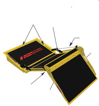
RAMP TERMINOLOGY
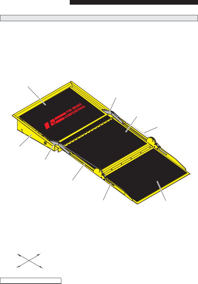
Ramp Terminology Illustration
Refer to the illustration below and the illustrations on
SDJH IRU LGHQWLÀFDWLRQ RI FRPSRQHQWV DQG FODULÀFDtion of direction terminology. Details regarding lift model variations, terminology, direction and components are provided on pages 4 and 5.
6XE ÁRRU
(Fixed)
Drive
Arm
®
Inboard Ramp
(Stage One)
Tension
Cable
Pan Weldment
Drive
Arm
Vertical
Side Plate
(Barrier)
Hand |
Outboard |
|
Hold |
||
Ramp |
||
|
||
|
(Stage Two) |
IN |
RIGHT |
LEFT |
OUT |
As viewed from outside the vehicle 

Page 2
RAMP TERMINOLOGY
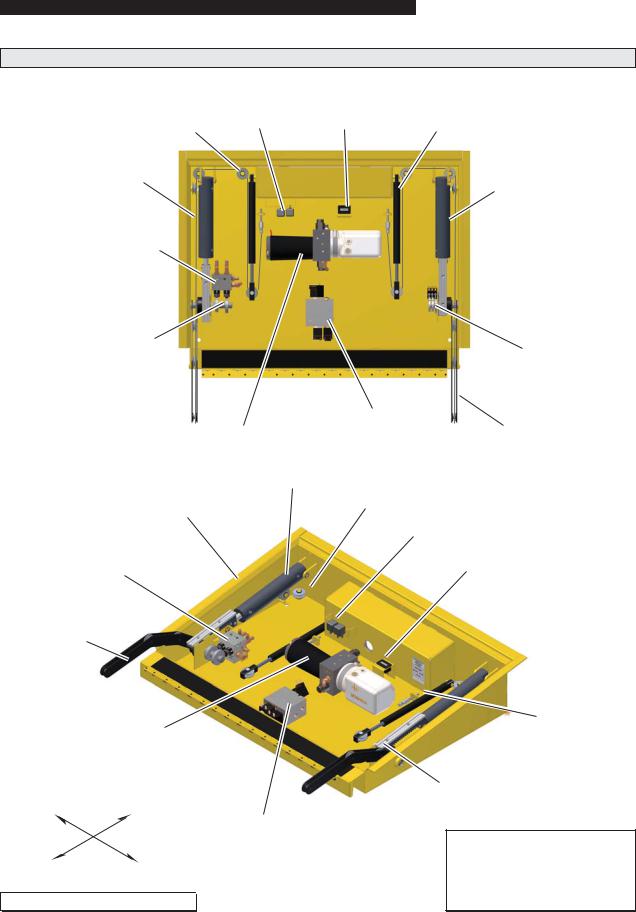
Ramp Components Terminology Illustration
|
Relays |
Counter |
Cable Tension |
Cable Pulley |
Gas Spring |
Tension Cable
Cylinder
Remote
Hydraulic Block
(BF3248Y &
BF3748Y Only)
Cam/Hydraulic
Assembly (BF3248Y & BF3748Y Only)
Pan Weldment
Cam/Hydraulic
Assembly (BF3248Y & BF3748Y Only)
Ramp Drive Arm
Pump
LEFT |
IN |
OUT |
RIGHT |
As viewed from outside the vehicle 

Cam/Microswitch
Assembly
Pump |
Remote Valve Block |
Ramp Drive Arm |
(BF3248YP Only) |
Cylinder
Cable
Pulley
Relays
Counter
Cable Tension
Gas Spring
Cam/Microswitch
Assembly
Remote Valve Block
(BF3248YP Only)
Note: The tension cable, sub
ÁRRU DQG WUDQVLWLRQ WKUHVKROG plate removed from these illustrations for clear view.
Page 3

RAMP TERMINOLOGY
Introduction
Braun RA300 Series Transit |
The RA300 provides fully auto- |
Instructions are provided for |
Ramps (to be referred to as |
matic operation of ramp functions. |
manual operation of the ramp |
RA300 throughout this manual) |
The electric/hydraulic system is |
in event of power or equipment |
DUH GHVLJQHG IRU XVH LQ ORZ ÁRRU |
controlled by two relays which ac- |
failure. See Manual Override |
transit vehicles. The RA300 |
tivate the hydraulic pump in oppo- |
on the following page for further |
provides vehicle access to people |
site directions for deploy and stow |
details. |
with disabilities (wheelchair pas- |
functions (powering a dual-acting |
|
sengers or standees using other |
hydraulic cylinder). No sensitive |
Read and become familiar with |
type mobility aids). The commer- |
electronic controls or sensors are |
all operation safety precautions, |
cial oriented ramp is ADA compli- |
required for operation. |
pre-operation notes and details, |
ant (dependant upon installation |
|
operating instructions and manual |
height). See the Installation sec- |
All RA300 ramp models feature |
operating instructions before at- |
WLRQ IRU $'$ VSHFLÀFDWLRQV |
gravity down "drift" during the |
tempting operation. |
|
deploy cycle. When deploying |
|
The self-contained “drop-in” unit |
the ramp, the motor stops running |
Terminology: Become familiar |
requires no remote pump, exter- |
when the ramp reaches an ap- |
with the terminology that will be |
nal hydraulic lines or pre assem- |
proximate 45° angle. The ramp |
used throughout this manual. |
bly. The hydraulic and electrical |
continues to slowly lower the |
Become familiar with the iden- |
components are internal and eas- |
remaining distance by the force of |
WLÀFDWLRQ RI 5$ FRPSRQHQWV |
ily accessible. A single electrical |
gravity. |
and their functions. Contact your |
feed provides the power supply |
5DPS PRGHO QXPEHUV ZLWK VXIÀ[ |
sales representative or call The |
(12 volt or 24 volt), the ground, a |
Braun Corporation at 1-800-THE |
|
ramp OUT signal (+), a ramp IN |
"Y" are hydraulic fold with gravity |
LIFT® if any of this information is |
signal (+) and various indicator |
down "drift" feature when deploy- |
not fully understood. |
signals. |
ing and stowing. When stowing |
|
|
the ramp and it folds inward be- |
Direction: The terms “left”, |
The RA300 features a 32” wide |
yond the 15° shut off point, gravity |
“right”, “in” and “out” will be used |
ramp in a 34” wide package. A |
lowers the ramp to the pan. |
throughout this manual to indicate |
´ÁRRU SRFNHWµ EXLOW LQWR WKH FKDV- |
|
direction (as viewed from the out- |
VLV ÁRRU V\VWHP DOORZV IRU VLPSOH |
Ramp model numbers with suf- |
side of the vehicle looking directly |
installation (dimensional require- |
À[ <3 DUH K\GUDXOLF SRZHUHG |
at the ramp). Refer to the Termi- |
PHQWV VSHFLÀHG LQ WKH ,QVWDOODWLRQ |
throughout the stow cycle (to full |
QRORJ\ ,OOXVWUDWLRQV IRU FODULÀFDWLRQ |
section). |
stow). The hydraulic system re- |
of direction terms. |
7KH 5$ LV VSHFLÀFDOO\ GH- |
mains pressurized while the ramp |
|
is in the stowed position. |
|
|
signed to be operated by an |
|
|
attendant. The ramp installer |
The pressure relief valves built |
|
provides an appropriate control |
into the pump prohibit the ramp |
|
switch for the end user. Con- |
from lifting (raising) with approxi- |
|
squently, the operating instruc- |
mately 20 pounds or more on the |
|
tions contained in this manual |
ramp. |
|
are generic due to the limitless |
|
|
variables. |
|
|
Page 4

RAMP TERMINOLOGY
Ramp Components
Refer to the Terminology Illustrations on pages 2 and 3.
Pan Weldment (Housing):
The pan is the stainless steel (casing) mounted in the vehicle
ÁRRU V\VWHP ZKLFK FRQWDLQV WKH hydraulic pump and electrical components that power the ramp electric/hydraulic systems. The
À[HG VXE ÁRRU FRYHU SURWHFWV WKH
components from above. The cover is easily removed for access to drive components. The
VXE ÁRRU SURYLGHV DQ DQWLVNLG surface for entry and exit when the ramp is deployed. The RA300 stows (folds) onto the sub
ÁRRU SURYLGLQJ DQ XQREVWUXFWHG antiskid surface for entry and exit when the ramp is not in use.
Ramp Assembly: The ramp assembly is made of an inboard ramp section (stage one) and an outboard ramp section (stage two). Each aluminum ramp section features vertical side plates and full antiskid surface.
Drive Arm Assembly:
The cylinder driven three stage drive arm assembly deploys and stows the ramp assembly.
Ramp Actions and Functions
Deploy: Deploy is the action of the ramp assembly extending and unfolding to ground level when the DEPLOY (OUT) switch* is activated (*installer supplied).
Stow: Stow is the action of the ramp assembly raising and folding inward to stow position when the STOW (IN) switch* is activated (*installer supplied).
Stow Position: Stow position is achieved when the two stage ramp assembly is fully retracted and folded (resting fully on the pan weldment).
Manual Override: Manual operation is achieved without the use of any mechanical release or complicated procedures. Simply use the Hand Holds provided on
the ramp assembly to manually deploy or stow the ramp. Minimal physical effort is required to
URXWH WKH K\GUDXOLF ÁXLG WKURXJK the system. Slow steady motion results in the least resistance and easy operation. The faster you attempt to manually operate the ramp, the greater the resistance. See Ramp Manual Operation on page 11 for further details.
Page 5
RAMP OPERATION
Safety Symbols
|
SAFETY FIRST! Know That.... |
|
|
|
|
|
|
|
|
|
|
|
|
|
|
All information contained |
|
|
|
|
|
|
|
|
|
|
|
|
A |
B |
|
|
WARNING |
|
|
C |
|
|
CAUTION |
|
|
|
in this manual and |
|
|
|
|
|
|
|
|||||
supplements (if included), is pro- |
|
|
|
|
|
|
|
|
|
|
|
||
|
|
|
This symbol indicates |
|
|
|
|
|
This symbol indicates |
|
|||
vided for your safety. Familiarity |
|
|
|
|
|
|
|
|
|
||||
with proper operation instructions |
|
|
|
important safety |
|
|
|
|
|
important information |
|
||
as well as proper maintenance |
|
|
|
information regarding |
|
|
|
|
|
regarding how to |
|
||
procedures are necessary to en- |
|
|
|
a potentially hazard- |
|
|
|
|
|
avoid a hazardous |
|
||
sure safe, trouble free operation. |
|
|
|
ous situation that |
|
|
|
|
|
situation that could |
|
||
Safety precautions are provided |
|
|
|
could result in serious |
|
|
|
|
|
result in minor person- |
|
||
to identify potentially hazardous |
|
|
|
bodily injury and/or |
|
|
|
|
|
al injury or property |
|
||
situations and provide instruction |
|
|
|
property damage. |
|
|
|
|
|
damage. |
|
||
on how to avoid them. |
|
|
|
|
|
|
|
|
|
|
|
||
|
|
|
|
|
|
|
|
|
|
|
|||
D Note: $GGLWLRQDO LQIRUPDWLRQ SURYLGHG WR KHOS FODULI\ RU GHWDLO D VSHFLÀF VXEMHFW
These symbols will appear throughout this manual. Recognize the seriousness of this information.
Ramp Operation Safety Precautions
 WARNING
If the ramp operating instructions, manual operating instructions and/or ramp operation safety precautions are not fully understood, contact The Braun Corporation immediately. Failure to do so may result in serious bodily injury and/or property damage.
 WARNING
 WARNING
 WARNING
 WARNING
Read manual and supplement(s) before operating ramp. Read and become familiar with all safety precautions, preoperation notes and details, operating instructions and manual operating instructions before operating the ramp. Note: All transit agency personnel (drivers and ramp attendants) must read and become familiar with the contents of this manual and supplement(s) before operation.
Load and unload on level surface only.
Engage vehicle parking brake before operating ramp.
Provide adequate clearance outside the vehicle to accommodate the ramp before opening lift door(s) or operating ramp.
 WARNING
 WARNING
 WARNING
 WARNING
 WARNING
Inspect ramp before operation. Do not operate ramp if you suspect lift damage, wear or any abnormal condition.
Keep operator and bystanders clear of area in which the ramp operates.
/RDG DQG XQORDG FOHDU RI YHKLFXODU WUDIÀF
Open ramp door(s) fully and secure before operating ramp.
Do not overload or abuse. The rated capacity is 300 kilograms (660 pounds).
Page 6

RAMP OPERATION
Ramp Operation Safety Precautions (continued)
 WARNING Do not activate control switch(es) when anyone is near the area in which ramp operates.
 WARNING It is the responsibility of the attendant to oversee and assist ramp passengers.
 WARNING The wheelchair passenger and/or attendant must ensure the ramp is fully deployed before exiting the vehicle.
 WARNING Attendants must never operate the vehicle, the ramp or attend to passengers if intoxicated.
 WARNING Intoxicated passengers should not be allowed to board the vehicle.
 WARNING Wheelchair passengers must position and secure (buckle, engage, fasten, etc.) the wheelchair-equipped occupant seat belt before loading onto the ramp.
 WARNING Be aware of the ramp slope (angle).
 WARNING Wheelchair passengers should not raise front wheelchair wheels (pull wheelie) when on the ramp.
 WARNING The wheelchair must be positioned in the center of the ramp when loading and unloading.
 WARNING Keep ramp owner’s manual in ramp-mounted vehicle at all times.
 WARNING 0DLQWHQDQFH DQG OXEULFDWLRQ SURFHGXUHV PXVW EH SHUIRUPHG DV VSHFLÀHG LQ WKLV PDQXDO E\ DXWKRUL]HG FHUWLÀHG VHUYLFH SHUVRQQHO
 WARNING Never modify (alter) a Braun Corporation ramp.
 WARNING Do not use accessory devices not authorized by The Braun Corporation.
 WARNING Do not remove any guards or covers.
 WARNING If the information contained in this manual is not fully understood, contact The Braun Corporation immediately.
 WARNING )DLOXUH WR IROORZ WKHVH VDIHW\ SUHFDXWLRQV PD\ UHVXOW LQ VHULRXV ERGLO\ LQMXU\ DQG RU SURSerty damage.
Page 7

RAMP OPERATION
Pre-Operation Notes and Details
The RA300 Ramp provides vehicle access to people with disabilities (wheelchair passengers or standees using other type mobility aids). The commercial oriented RA300 Ramp is operated by the transit vehicle driver/attendant. Unless your transit agency has a published policy stating that driver/attendants do not aid ramp passengers, safe entering and
exiting of ramp passengers is the responsibility of the driver/ attendant.
As stated in the Ramp Operation Safety section, all information in this manual is provided for the safety of passengers, attendants and bystanders. Recognize the seriousness of this information.
Read and become familiar with all ramp operation safety precautions, pre-operation notes and details, operating instructions and manual operating instructions before attempting ramp operation procedures or assisting ramp passengers boarding and exiting the vehicle.
Ramp Access Doors and Interlocks
Attendants must become familiar with the vehicle ramp access door system and interlock(s), as well as the proper operation of the ramp.
Vehicle ramp access door con-
ÀJXUDWLRQV DQG RSHUDWLRQ SURFHdures vary. Ensure the ramp door is fully open before activating the ramp (an interlock typically prevents ramp operation unless the door is fully open). Attendants and passengers must keep clear of the area in which the power door operates. Ensure the path is clear before closing the door. Be sure the door is fully closed before attempting to drive the vehicle (interlocks typically ensure this).
Interlocks are required by nearly all transit authorities. Vehicle interlocks typically prevent vehicle motion if the ramp is not stowed. In some cases, the ramp cannot be operated if interlock conditions are not met. Interlock requirements may include: the vehicle transmission must be engaged in Park, the parking brake must be engaged, the ramp access door must be fully open and/or others. Multiple interlocks may exist.
Instructions for operation of interlocks and door systems will not be addressed in this manual due to the variety of procedures required for operating them.
General instructions for safe operation of the ramp are provided. Ramp safety and ramp passenger safety information is included. It is the responsibility of the attendant to properly open and close the ramp access door(s), to activate interlock(s), to properly activate the ramp power functions as well as assist ramp passengers.
Do not operate the ramp if you suspect ramp damage, wear or any abnormal condition. Discontinue use immediately and contact The Braun Corporation at 1-800-THE LIFT®. One of our national Product Support representatives will direct you to an authorized service technician who will inspect the ramp.
Page 8
RAMP OPERATION
Operation Procedure Review
The Braun Corporation recommends that transit agency supervisors and driver/attendants review the safety precautions and operation procedures appearing in this manual with the ramp sales representative (or vehicle converter) before attempting ramp operation.
Any questions or concerns can be answered at that time. Operate the ramp through all functions to ensure the proper use and operation is understood.
Transit agency supervisors should train and educate all driver/attendants on the proper use and operation of the vehicle, door system, interlock(s), ramp and ramp passenger safety.
The ramp owner’s/service manual must be stored in the rampequipped vehicle at all times.
 WARNING
Read and become familiar with all ramp operation safety precautions, preoperation notes and details, operating instructions and manual operating instructions prior to operating the ramp. If this information is not fully understood, contact The Braun Corporation immediately. Failure to do so may result in serious bodily injury and/or property damage.
Preventive Maintenance:
Maintenance is necessary to ensure safe and trouble free operation. General preventive maintenance consisting of careful inspections and cleaning the ramp system should be a part of your transit agency’s daily service program. Simple inspections can detect potential operational problems.
Regular preventive maintenance will reduce potential operation downtime and increase the service life of the ramp, as well as possibly detecting potential hazards.
A generic Daily Preventive Maintenance Schedule is provided in this manual for your transit agency’s use. The form can be tailored to your particular application.
Exposure to harsh weather, environmental conditions, or heavy usage may require more frequent maintenance and lubrication procedures.
Preventive maintenance visual inspections do not take the place
RI WKH SURFHGXUHV VSHFLÀHG LQ the Maintenance and Lubrication Schedule provided in this manual. Refer to the Maintenance and Lubrication section in this manual for further details.
Page 9
Before operating the ramp, park the vehicle on
D OHYHO DUHD DZD\ IURP YHKLFXODU WUDIÀF 3ODFH the vehicle transmission in “Park” and engage the parking brake. Meet all other interlock conditions (as equipped). Activate the vehicle “kneel” system to lower the vehicle (if so equipped). Lowering the vehicle reduces the slope of the ramp.
be aware of any special needs and/or procedures required for safe transport of wheelchair passengers.
Do not attempt to load or unload a passenger in
D ZKHHOFKDLU RU RWKHU DSSDUDWXV WKDW GRHV QRW ÀW on the ramp. Do not exceed the 660 pound (300 kilograms) load capacity of the ramp. Passengers should enter and exit one at a time. The attendant should not board the ramp with the passenger except when assistance is required and the load capacity is not exceeded. Always return the ramp to the stowed position when not in use.
 WARNING
Keep clear of area in which ramp operates.
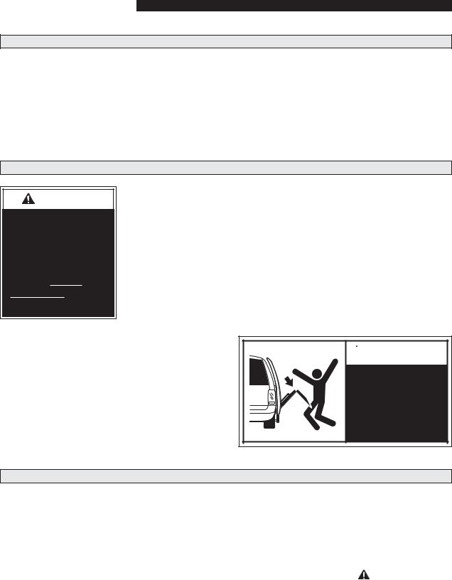
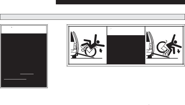
Stow Gravity Down Drift ("Y" ramp models only):
When stowing the ramp and it reaches an approximate 15° angle (shut off point), gravity lowers the
UDPS WR WKH SDQ ÁRRU
Note: Pump |
|
|
|
|
CAUTION |
|
|
motor shut |
|
|
|
off points are |
|
|
|
Allow ramp to deploy |
|
||
microswitch |
|
|
|
DGMXVWDEOH |
|
fully before boarding. |
|
|
|
Failure to do so may |
|
|
|
result in damage. |
|
|
|
|
|
|
|
|
|
|
|
|
RAMP OPERATION |
||||
|
|
|
|
|
|
|
|
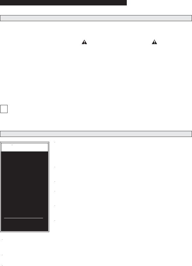
Ramp Manual Operation |
|
|
|
|
|
|
|
If you experience power or equipment failure, the |
|
|
|
|
|
|
|
|
|
|
|
|
Figure A |
|
|
ramp can be manually stowed and deployed. The |
|
|
|
|
|
|
|
|
|
|
|
|
|
|
|
RA300 ramp must be manually operated by an at- |
|
Keep clear of area |
|
|
|
||
tendant. |
|
|
|
|
|||
|
where ramp side plates |
|
|
|
|||
Two oval-shaped HAND HOLD slots are provided |
|
VWRZ LQ SDQ ÁRRU |
Keep clear of |
||||
|
|
|
|
hinged areas. |
|||
|
|
|
|
||||
on the ramp (see Figure A). Carefully unfold and |
|
|
|
|
|
Keep clear of |
|
fold the ramp using the HAND HOLDs. |
|
|
|
|
|
||
|
|
|
|
|
tension cables. |
||
|
|
|
|
|
|
||
Keep clear of the area in which the hinged RA300 |
|
|
|
|
|
Hand |
|
ramp sections fold and unfold. Keep clear of the |
|
|
|
|
|
Hold |
|
area where the inboard ramp side plates stow in the |
|
|
|
|
|
|
|
SDQ ÁRRU .HHS FOHDU RI WHQVLRQ FDEOHV DQG GULYH |
|
|
|
|
|
|
|
arms. Remember to use good body mechanics |
|
|
|
|
|
|
|
when folding and unfolding the ramp. |
|
|
|
|
|
|
|
The safety precautions addressed in the Ramp |
|
|
|
|
|
|
|
Power Operation section apply to manual operation |
Keep clear of |
|
|
|
|||
of the ramp also. Read and become familiar with |
hinged areas. |
|
|
|
|||
all ramp safety precautions. |
|
|
Hand |
|
|
|
|
|
|
Hold |
|
|
|
||
|
|
|
|
|
|
||
Note: Minimal physical effort is required to manu- |
|
|
|
|
|
|
|
ally operate the ramp. Slow steady motion results |
|
|
|
|
|
|
|
in the least resistance and easy operation. The |
|
|
|
|
|
|
|
faster you attempt to manually operate the ramp, |
|
Use HAND HOLDs to carefully |
|||||
the greater the resistance. |
|
unfold and fold the ramp. |
|||||
|
|
|
|
|
|
|
|
Ramp Passenger Safety |
|
|
|
|
|
|
|
|
|
|
|
|
|
|
|
Unless your transit agency has a published policy stating that driver/attendants do not aid ramp (disabled) passengers, it is the responsibility of the driver/attendant to ensure that ramp passengers enter and exit the vehicle on the ramp in the safest manner.
ADA requirements state that transit drivers/attendants must assist with attaching and removing wheelchair and occupant restraint belts.
Ramp passengers (wheelchair passengers and standees), and attendants must use common
VHQVH DQG JRRG MXGJPHQW UHJDUGLQJ UDPS VDIHW\
Each wheelchair passenger (or standee) has a unique set of physical abilities combined with the physical characteristics of his or her wheelchair (or other mobility aid) that dictate the method in which he or she will enter and exit the vehicle.
Wheelchair attendants should be instructed on any special needs and/or procedures required for
safe transport of wheelchair passengers. Follow all safety instructions regarding torso restraints, stability, balance, weight distribution and use of atten-
GDQWV DV VSHFLÀHG LQ WKH RZQHUҋV PDQXDO VXSSOLHG with the passenger’s wheelchair (or other mobility aid). Wheelchair passengers must determine, establish and practice ramp boarding and exiting procedures under the direction of the their personal health care professional and wheelchair representative. Those procedures should be conveyed to the ramp attendant. Know your passengers abilities and needs for optimum safety.
Attendants must never operate the vehicle, the ramp or assist passengers if intoxicated. Intoxicated passengers should not be allowed to board or exit the vehicle.
Passengers should be positioned in the center of the ramp at all times. Attendants and ramp passengers must be able to clearly view the ramp whenever boarding and exiting the vehicle. The
Page 11
RAMP OPERATION
Ramp Passenger Safety (Continued)
 WARNING
Position and fasten the wheelchairequipped occupant seat belt before loading onto the wheelchair ramp. Failure to do so may result in serious bodily injury and/or property damage.
attendant and/or wheelchair passenger must ensure the ramp is fully deployed before exiting the vehicle. Observe your passengers at all times when they are entering and exiting the vehicle.
Wheelchair-Equipped Occupant Seat Belts: Wheelchair passengers should position and buckle their wheelchair-equipped seat
EHOW WRUVR UHVWUDLQW DV VSHFLÀHG by the manufacturer, before loading onto a wheelchair ramp.
Different types of disabilities require different types of wheelchairs and different types of wheelchair-equipped occupant restraint belt systems (torso restraint). It is the responsibility of the wheelchair passenger to have his or her wheelchair equipped with an occupant restraint (seat belt) under the direction of their health care professional.
 WARNING
Be aware of ramp slope.
52217
Stabilizing Wheelchairs: Powered and manual wheelchairs are designed to remain upright and stable during normal operation. All activities which involve movement in a wheelchair have an effect on the combined center of gravity of the occupant and wheelchair. Be aware of the ramp slope (angle). The slope of the ramp has a direct effect on the center of gravity. The wheelchair passenger’s center of gravity and their ability to maintain stability and balance must be kept in mind by the wheelchair passenger and the attendant.
The aid of an attendant stabilizing the wheelchair is recommended for optimum safety. Wheelchair passengers who are unable to maintain stability and balance should not board a ramp without assistance. Counterbalance devices (anti-tippers) may be available from the wheelchair representative to enhance stability and balance.
Wheelchairs should be operated at a slow and constant speed when on the ramp. Wheelchairs should not accelerate suddenly
when on the ramp. Wheelchair passengers should not raise the front wheelchair wheels (pull wheelie) when on the ramp.
Wheelchair passengers who intend to enter and exit the vehicle without the assistance of an attendant must determine the safest and most practical method and orientation of entering and exiting based on the physical characteristics of their personal wheelchair and his or her physical capabilities to maintain stability while the wheelchair is in motion on the ramp.
Wheelchair Attendants: When assisting a wheelchair occupant, remember to use good body mechanics. When the wheelchair is on the ramp, the attendant must grasp the push handles (or other) securely. Detachable wheelchair parts such as arms or leg rests must never be used for hand holds or lifting supports. Doing so could result in the parts being inadvertently detached from the wheelchair resulting in possible injury to the wheelchair occupant and/or the attendant.
Page 12
RAMP INSTALLATION
Safety Symbols
|
SAFETY FIRST! Know That.... |
|
|
|
|
|
|
|
|
|
|
|
|
|
|
All information contained |
|
|
|
|
|
|
|
|
|
|
|
|
A |
B |
|
|
WARNING |
|
|
C |
|
|
CAUTION |
|
|
|
in this manual and |
|
|
|
|
|
|
|
|||||
supplements (if included), is pro- |
|
|
|
|
|
|
|
|
|
|
|
||
|
|
|
This symbol indicates |
|
|
|
|
|
This symbol indicates |
|
|||
vided for your safety. Familiarity |
|
|
|
|
|
|
|
|
|
||||
with proper operation instructions |
|
|
|
important safety |
|
|
|
|
|
important information |
|
||
as well as proper maintenance |
|
|
|
information regarding |
|
|
|
|
|
regarding how to |
|
||
procedures are necessary to en- |
|
|
|
a potentially hazard- |
|
|
|
|
|
avoid a hazardous |
|
||
sure safe, trouble free operation. |
|
|
|
ous situation that |
|
|
|
|
|
situation that could |
|
||
Safety precautions are provided |
|
|
|
could result in serious |
|
|
|
|
|
result in minor person- |
|
||
to identify potentially hazardous |
|
|
|
bodily injury and/or |
|
|
|
|
|
al injury or property |
|
||
situations and provide instruction |
|
|
|
property damage. |
|
|
|
|
|
damage. |
|
||
on how to avoid them. |
|
|
|
|
|
|
|
|
|
|
|
||
|
|
|
|
|
|
|
|
|
|
|
|||
D Note: $GGLWLRQDO LQIRUPDWLRQ SURYLGHG WR KHOS FODULI\ RU GHWDLO D VSHFLÀF VXEMHFW
These symbols will appear throughout this manual. Recognize the seriousness of this information.
Installation / Service Safety Precautions
 WARNING
If installation, maintenance or repair procedures cannot be completed exactly as provided in this manual or if the instructions are not fully understood, contact The Braun Corporation immediately. Failure to do so may result in serious bodily injury and/or property damage.
 WARNING
 CAUTION
 WARNING
 WARNING
 WARNING
 WARNING
 WARNING
Read this manual and supplement(s) before performing installation, operation or service procedures.
,QVWDOODWLRQ VSHFLÀFDWLRQV DQG GLPHQVLRQV PXVW EH PHW
Remove any obstructions within the ramp mounting/operating area prior to beginning installation procedures.
Do not operate ramp prior to positive securement of the pan.
Check for obstructions such as gas lines, wires, exhaust, etc. before drilling or cutting during installation procedures.
Route all cables clear of exhaust system, other hot areas, moving parts, wet areas, etc.
5LVN RI HOHFWULFDO VKRFN RU ÀUH 8VH H[WUD FDUH ZKHQ PDNLQJ electrical connections. Connect and secure as outlined in Installation Instructions and Wiring Diagrams.
 WARNING
 WARNING
 WARNING
0HHW DOO UDPS SRVLWLRQLQJ DQG FOHDUDQFH VSHFLÀFDWLRQV DV GHWDLOHG LQ WKH 3RVLWLRQLQJ DQG
Clearance Checklist before operating ramp.
Maintenance and repairs must be performed only by authorized service personnel.
Perform maintenance and lubrication procedures exactly as outlined in the Maintenance and Lubrication Schedule contained in this manual.
Page 13
 Loading...