

Braun MOVIPORT C118 Series User Manual
Universal Hand Held Tachometer
MOVIPORT C118 Series
Manual
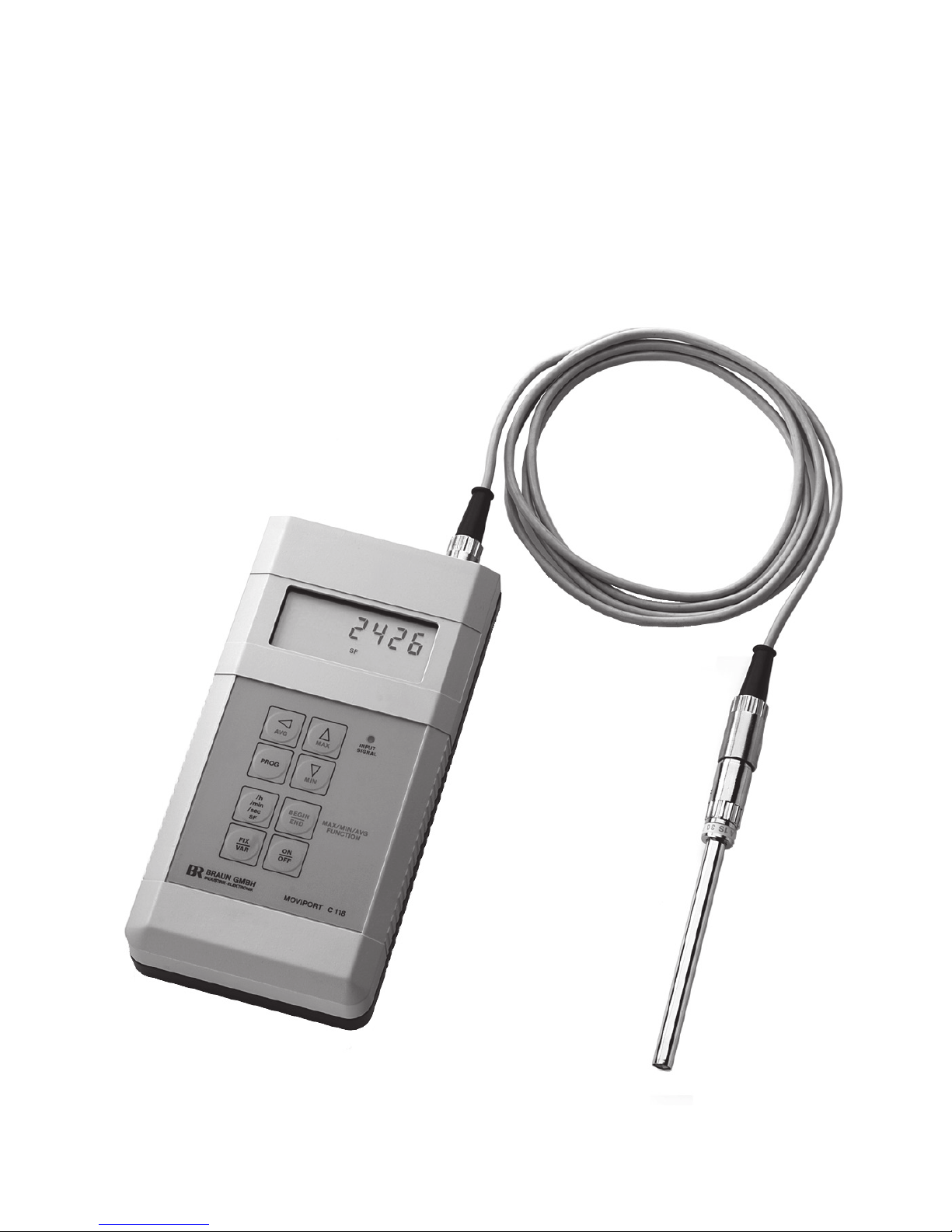
Hand Held Tachometer C118 + Cable SAK-2m + Sensor A1S30P95


1
Universal Hand Held Tachometer
MOVIPORT C118 Series
Manual
Contents
Page
C118 Versions and Accessories ........................................................................ 2
Specifications .................................................................................................... 3
Operational Elements ........................................................................................ 4
Short Form Instructions to Operation ............................................................... 5
Sensors and Cables fitting the C118 ................................................................. 6
Sensor Selection and Target Marking Directions ............................................. 7
Instrument Connections ..................................................................................... 9
Power Supply .................................................................................................. 10
Input Response ................................................................................................ 11
MAX/MIN Memory ........................................................................................ 12
Totalizing Function ......................................................................................... 12
FIX / VAR Operation Modes .......................................................................... 13
Programming Procedure and List of Steps ..................................................... 14
Parameter Functions
Shortest and Maximum Measuring Time Allowance ............................. 15
Computing (Scaling) Factor .................................................................... 16
Display of Speed and Frequency ............................................................ 16
Analog Output ......................................................................................... 17
Automatic Power Off .............................................................................. 18
Pre-Divider ............................................................................................. 18
Display of Totals ..................................................................................... 19
Parameters set on Delivery (Default Values) .................................................. 19
Notes to Optional Functions of C118
Data Interface RS232 at C118.1 and C118.3 .................................................. 20
Manual Preset of Sensitivity at C118.2 and C118.3 ....................................... 11
applicable since Serial No. 012535

2
Scope of the MOVIPORT C118 Series Overview
Ordering No.
C118BS
Equipment comprising
Standard Equipment
with battery-powered Instrument C118, Optosensor A1S30P95,
plug-in connector cable SAK-2m, marking aids, carrying case
C118.1BS
Instrument with RS232 Data Interface and adapter cable L3D01,
otherequipment as under C118BS
C118.2BS
Instrument with Manual Preset of Input Sensitivity,
otherequipment as under C118BS
C118.3BS
Instrument with RS232 Data Interface and adapter cable L3D01,
otherequipment as under C118.2BS
C118.2BP
Instrument with high efficiency sensor A1S36P95 with 5m firmly
attached cable, in place of A1S30P95+SAK-2m Equipment,
otherequipment as under C118.2BS
C118.3BP
Instrument with RS232 Data Interface and adapter cable L3D01,
otherequipment as under C118.2BP
Scope of Sensors and Cables to C118 see page 6
Extra Accessories
Application
Set of (not-rechargeable) batteries
Part No.
MN1500x4
Power Supply Unit (to feed the C118 immediately from mains
(100 V...240 V AC)
U1H008
Set of rechargeable cells in place of batteries
IECR6
Charger to IECR6 from 230 V AC
U1H009
Plug-in cable to output, 3 m long, BNC connectors at both ends
(one cable per output required)
U1H014
High reflection marking tape bag of 10 pieces
U1A006/10
roll of 4,5 m length
U1A006/1
Magneto-based adjustable sensor clamp
RS232 adapter cable between C118 and PC, 1,8 m length
U9A001
L3D01

3
Specifications
Measuring Function Principle
Pulse distance measurement with automatically extended number of periods,
as determined by a programmable* minimum measuring time allowance.
Low end of operating range programmable*, high end = 100 kHz.
Accuracy + 0.05 % + 1 in last active digit.
Special Function (SF) provides continuous totalizing of input pulses.
Modes of Operation
Push-button selection between FIX = straight tachometer function and
VAR = use of incorporated programmable* computing facilities.
Computing Facility to convert Measurements into other Variables
6 digits programmable* conversion factor, multiplying or dividing, representing
a roll circumference, or gear ratio, or transmitter factor, for instance.
Display
6 digits reading speed by selectable units .../sec, …/min, …/h, or totals (SF).
Decimals by automatic shifting (FIX mode) or firm on programmable position
(VAR mode).
Memory
Maximum, Minimum, Average, over a controllable period of time. Call to
display by push-button.
Signal Input
To pulses or AC voltage from 50 mV
eff
up to 60 volts. Selection of automatic
response characteristics. Programmable* frequency pre-divider 001 …255.
Sensor supply 5 volts / max 60 ma.
Analog Output
0 … 4 volts, short circuit protected. Source impedance 100 ohms. Linearly
related to display. Low and high end of conversion range programmable* for
spread reading. Resolution 12 bit.
Pulse Output
Square wave shaped, with its sequence repeating the input, reduced by programmed pre-divider. 5 volts TTL-level.
Power Supply
Inserted batteries (4xMN1500), or rechargeable cells (IECR6). Alternatively by
supply unit (U1H008) from mains 100 ... 250 volts AC, plug-in connection.
Operating Conditions
Ambient Temperature -10 … + 55 °C (14 … 130 °F). Protection grade IP 54.
Dimensions 195 x 100 x 40 mm. Weight (with batteries) approx. 480 grams.
* Programming effective only in VAR mode. Parameter List on page 14.
For additional specifications of special versions see corresponding chapters.
4
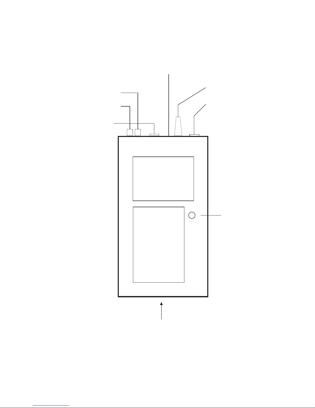
Operational Elements
Input socket to
sensor connection
Turning knob to preset the
maximum input sensitivity
(C118.2 and C118.3 only)
Jack to supply
unit U1H008
Display reading
measurements with
their time reference,
operating mode, program Step No and its
p
aramete
r
Key board
to select
the functions
(see instructions)
Response indicator
Battery case underneath
2x BNC jacks for
pulse output
and
analog output
Socket for
Data interface

5
Short Form Instructions to Operation
Further explanation on page
FIX Operation Mode
no programming at all
required
VAR Operation Mode
programming facilities
get valid
Signal Input
Response
Characteristics
Time reference of
Readings
Analog Output
MAX / MIN / Average
ON / OFF
13
14
9
11
13
17
12
10
Immediate direct tachometer function.
Range 30 / min up to 100,000 / sec,
valid for 1 mark per revolution.
Display with automatic decimal point:
Last digit = 0.x 0.0 0x
Details on page 13.
actuate key FIX/VAR to switch to VAR.
Programming procedure and function instructions start on page 14.
plug in sensor immediately into socket,
or use connection cable.
For normal operation use predetermined
automatic mode. Manual knob preset at
C118.2 and C118.3.
To eliminate the automatic mode, keep
AVG key depressed, and actuate FIX
key for approx. 1 sec. Display indicates
AUTO OFF.
Use same procedure to return to automatic response.
select by /h /min /sec key for speed, or
select totalizing by SF (its period being
effective from first actuation of BEGIN
key to subsequent one = END).
effective in both modes FIX and VAR,
range as set by program.
memorized between BEGIN and END
(key actuation). Call to display by keys
MAX, MIN, or AVG.
by ON/OFF key. Programmable to
automatic OFF after 10 min idling.

6
Sensors and Cables fitting the C118
Application Characteristics Part No.
Optoelectronic Sensor as standard, 95 mm shaft
(part of equipment C118BS, C118.1BS, C118.2BS and
C118.3BS).
A1S30P95 *
same, with short shaft 35 mm. A1S30P35 *
Optosensor, with increased light intensity, with 5m
cable firmly attached (part of C118.2BP and C118.3BP).
A1S36P95-5m
same, with short shaft 35 mm, and angularly
attached cable, for narrow space applications.
A1S36WP35-5m
Laser type sensor for scanning distance up to 2 m,
target to be marked with high reflection tape U1A006.
A1S37P *
Sensing wheel, twin type, wheel 63 mm,
1000 pulses/meter for length detection,
Speed measuring range 0… 1200 m/min.
A1L04B200 **
Sensing wheel, twin type, wheel 159 mm,
1000 pulses/meter for length detection,
Speed measuring range 0… 3000 m/min.
A1L05B500-5V **
Speed sensor on differential Hall-effect basis, detecting
steel profiles, or magnets, at any speed, under tough conditions, under oil or water.
A5S07B50-2mP **
Speed sensors on magnetic-inductive (active) basis,
to detect varying external magnetic fields. Specials for
speed measurement of turbochargers on ships.
Sensor series
A2S… ***
*) connection cable type SAK
(in standard equipment with 2 meters length)
**) connection cable type L3A25BP
***) connection cable type L2A16BP
All cables available with length of 2 m, 5 m, 10 m.
 Loading...