

Page 1
Braun Corporation FMVSS No. 403 Quick Reference Installation Sheet 31312 Rev. A
Braun Corporation FMVSS No. 403
Quick Reference Installation Sheet 31312
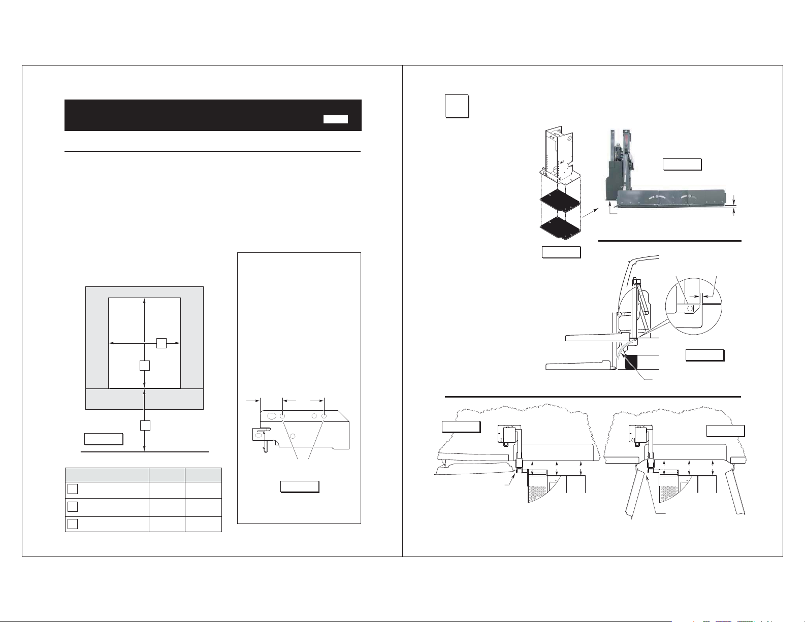
“DOT — Private Use Lift”
NHTSA Vehicle Physical Requirements
OEM (Van) Chassis Floor Requirements
Nonmodied OEM full size van oors meet
all requirements for NV05. Nonmodied
OEM mini van oors meet all requirements
for NMV05.
Door Opening Dimensions
Vehicle lift access door opening
must meet specied dimensions.
Vehi cle
Door
Opening
B
A
Lowered (Drop) Floor Requirements
Must meet or exceed nonmodied
OEM oor section.
“1992” and Newer Ford Slide Door
1. Remove the lower slide door stop.
2. With Power Door: Door stop not
used.
Without Power Door: Drill (2) holes
in the lower door stop at dimensions
shown in Figure B.
3. Replace door stop, locating on the
(2) drilled holes (provides adequate
clearance).
2-3/4"1-7/16"
Rev: A
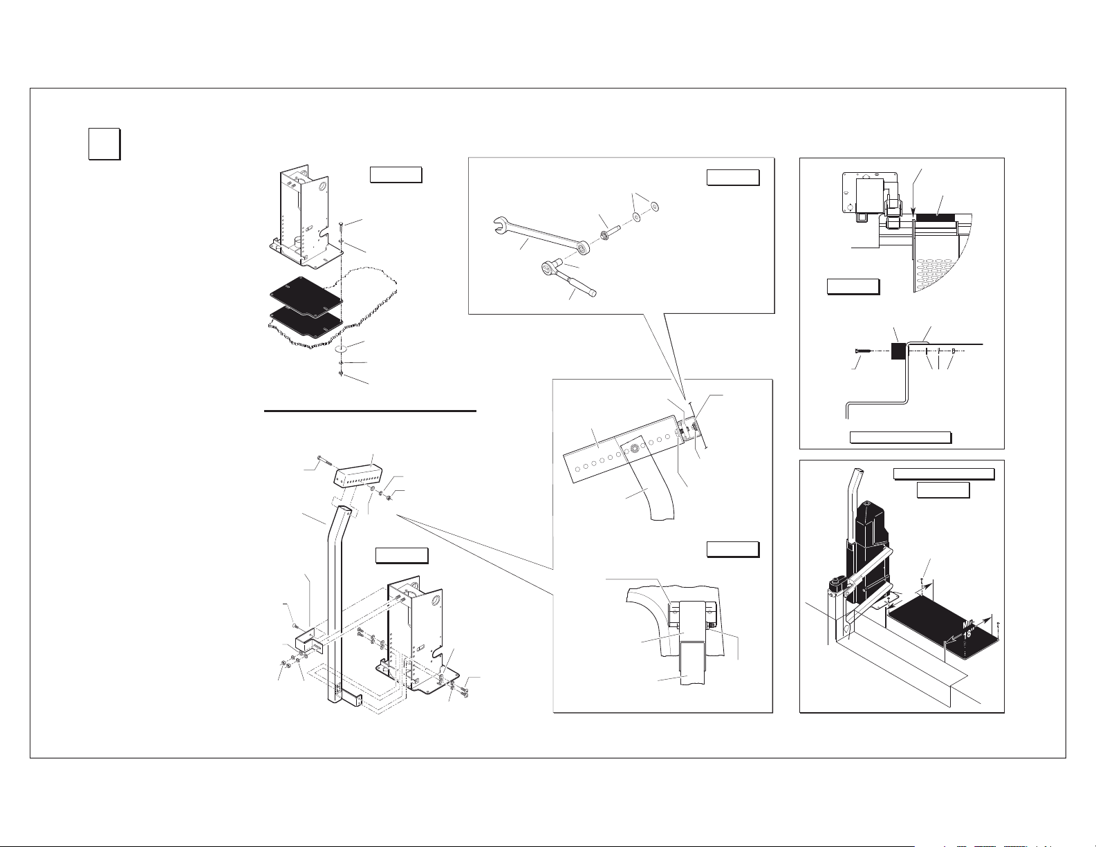
Position Lift
1
Place lift in approximate
position. Note: Hoist
or other lifting device is
recommended.
Position wedge plate(s)
to achieve a 1/2" pre-
load at right inboard
corner of platform. See
Figures C and D.
Clearances
Minimum 1" clearance
between lift and vehicle.
See Figure E.
Maximum 1/2" between
inboard locator and oor
when locator is deployed.
See Figure E.
Minimum 3/4" clearance
between door and vertical arm. See Figures F
and G.
Frame
Tube
Wedge
Plate
W
edge
Plate
Figure C
Figure D
Position wedges as
needed for 1/2" preload.
Inboard
Locator
Minimum 1" Clearance
Stepwell
Figure E
Maximum
1/2"
Floor
1/2"
Figure A
Dimension
Minimum Clear Door
A
Opening Height
Clear Door Opening
B
C
Width
Maximum
Floor-to-Ground
C
Minivan
42"
31-1/2"
29"
Ground Level
Full Size
Van
48"
39-1/2"
29"
Drill (2) 5/16" diameter holes.
Figure B
Figure F
Slide Door
Minimum 3/4"
Wall
Clearance
Floor
(ALIGNED) PARALLEL (ALIGNED)
Wall
Rear Swing Door
Figure G
Floor
(ALIGNED) PARALLEL (ALIGNED)
Minimum 3/4"
Clearance
Wall
Front Swing Door
Page 2
Braun Corporation FMVSS No. 403 Quick Reference Installation Sheet 31312 Rev. A
Secure Lift
2
1. Temporarily secure base plate by
installing sheet metal screws in
base plate slots.
2. Secure vertical mounting brace
and upper mounting bracket to
frame tube. See Figure I.
3. Temporarily assemble upper adjustment bracket and upper mounting channel. See Figure K. Position assembly and mark mounting
holes on van wall (C pillar).
Carefully drill 5/16" diameter wall
mounting holes. Secure upper
mounting channel to wall (C pillar)
using expanding Fab-Lock bolts
(minimum 2). See Figure J.
4. Secure upper adjustment bracket
and upper mounting channel assembly to vertical mounting brace.
5. Carefully operate lift through all
functions checking for clearances
(specied in Figures D-I). Adjust
lift position and/or upper mounting
hardware as needed.
6. Drill 3/8" diameter holes through
oor using the corner holes in the
base plate as a template. Refer to
Figure H. Insert 3/8"-16 hex bolts
and secure below oor as specied in Figure H (bolt lengths as
required per application).
Tighten all mounting hardware
securely. All fasteners must meet
FMVSS 571.403 Section 6.3.
7. Cut upper adjustment bracket off
ush with mounting brace and
install foam padded cover using
cable ties. Note: Cover power
unit before cutting bracket.
8. Position and secure docking bumper. See Figure L.
9. Position and secure warning sensor mat as specied in Figure M.
Connect wiring harness to lift as
shown in Figure P.
Position
wedges
as needed.
All Positions
3/8-16 x 3"
Mounting
5/16-18 x 3/4"
Flat Head
Screw
5/16"
Flat
Washe r
5/16"
Hex
Nut
Plate
Plate
Hardware
Typical
Hex Bolt
Vertical
Brace
Upper
Mounting
Bracket
Washer
Frame
Tube
Wedge
Wedge
5/16"
Lock
• One in each corner.
• Lengths as required
Floor
Adjustment
Bracket
5/16" Flat
Washe r
ecarB
gn
i
t
nu
oM
la
c
itre
V
Figure H
3/8-16 Hex Bolt
(Minimum 4)
per application.
5/16" Flat Washer
3/8" Body Washer
3/8" Lock Washer
3/8-16 Hex Nut
Upper
3/8" Lock
Washe r
3/8" Hex
Figure I
Nut
Frame
Tube
5/16" Lock
Washe r
5/16" Flat
Washe r
Fab-Lock Bolt Installation
1. Remove rubber
washer and install
1/4" at washers.
5/8" Wrench
3. Place a 5/8"
wrench onto
bolt head and
secure tightly
Hardware
typical
opposite side
5/16-18 x 7/8"
Button Head
Cap Screw
1/4" Flat Washers
Fab-Lock Bolt
5/16" Socket
Ratchet Wrench
Upper
Adjustment
Bracket
Vertical
Mounting
Brace
Note: Cut bracket off ush with
mounting brace and install foam
padded cover using cable ties.
Upper
Mounting
Channel
Adjustment
Bracket
2. Insert Fab-Lock bolts (minimum
2) fully through mounting channel
and C pillar.
4. Place a 5/16" socket onto the inner
screw and tighten (turn clockwise).
5. Turn socket until Fab-Lock has
expanded against metal surface.
3/8-16 Slide Nut
Fab-Lock Bolt
3/8-16 x 1"
Hex Cap Screw
Lock Washer
(Qty: 2)
Wall (C Pillar)
Upper
Vertical
Mounting
Brace
Figure J
Upper
Mounting
Channel
with
Figure K
3/8-16 x 3"
Hex Bolt
with
Lock Washer
and Hex Nut
Figure L
Docking
Bumper
3/8-16 x 2"
Hex Bolt
(Qty: 2)
Stepwell
Docking Bumper
Edge of Finished Floor
Note: Threshold warning
mat must be installed on a
at, rigid surface.
Outer Pivot
Docking
Bumper
Platform
Trim
Floor
5/16" Flat Washer
3/8" Lock Washer
3/8-16 Hex Nut
Threshold Warning
Figure M
#10-16 x 1-1/2"
Wafer Head Phillips
Self-Drilling Screw
(Qty: 4)
Min.
18"
Threshold
Warning
Page 3
Braun Corporation FMVSS No. 403 Quick Reference Installation Sheet 31312 Rev. A
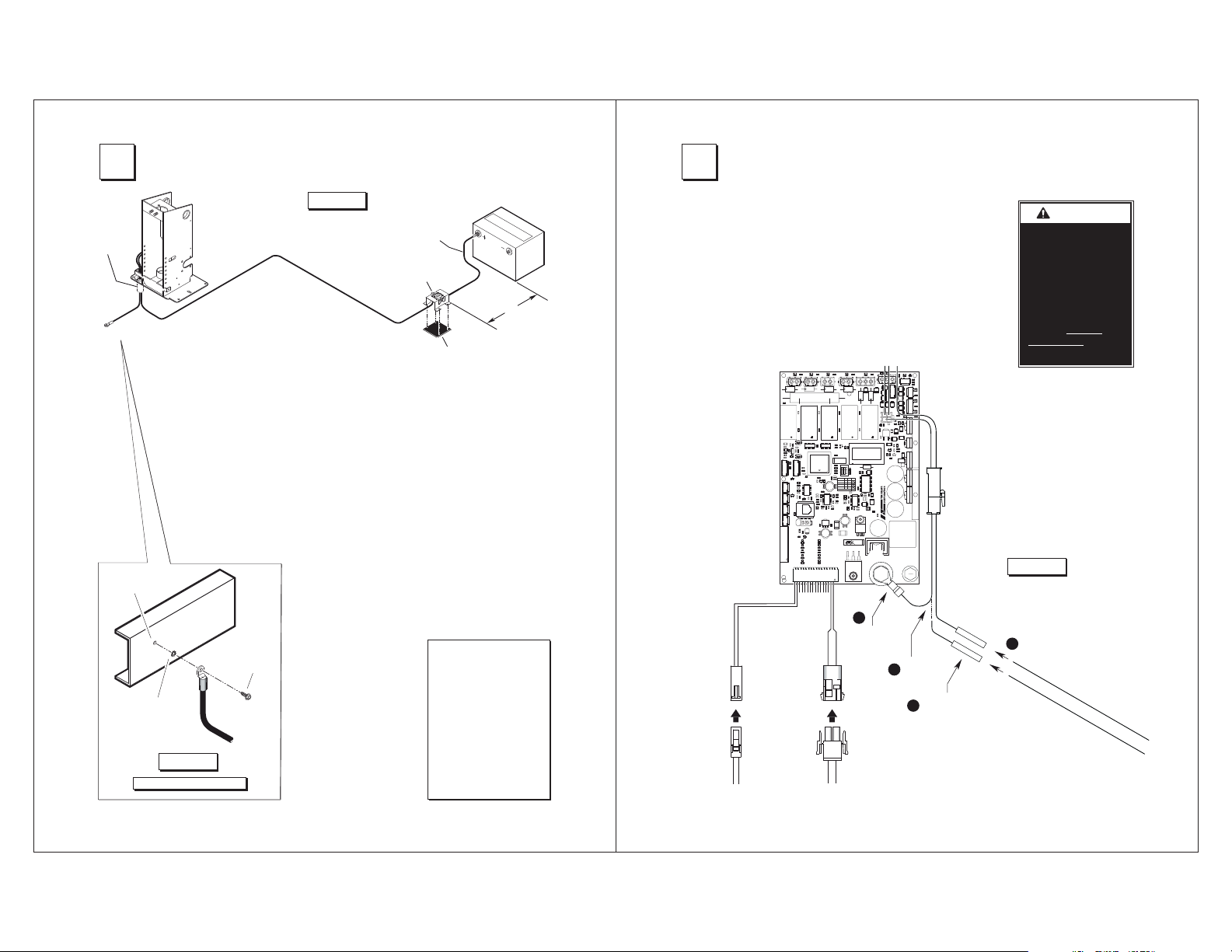
3
Grommet
Ground
Cable
9/32" Diameter
Pilot Hole
Attach Power and Ground Cable
Figure N
Frame
ube
T
1. Drill 1-1/8” diameter grom-
met access hole. Check
under the vehicle for
obstructions.
2. Insert grommet. Secure
grommet with two self-tap
screws.
Power Cable
3. Route ground and power
cables through grommet.
Route cables clear of
exhaust, other hot areas
and moving parts.
4. Connect ground cable to
vehicle framing member
(see detail below).
5. Attach power cable to
Auxiliary terminal of
Circuit Sentry. Attach one
end of 18" lead cable to
the Battery Circuit Sentry
terminal.
Lead
Cable
Pos.
Neg.
Circuit
Sentry
Bat.
Aux.
1/8" x 4" x 4"
Plastic
Locate Circuit Sentry within
12" of positive (+) battery
terminal. Mount Circuit
Sentry with four self-tap
screws. Sandwich 1/8"
x 4" x 4" plastic between
Circuit Sentry and mounting surface.
6. Carefully connect opposite
end of lead cable to Posi-
tive (+) post of battery.
12"
Max.
Connect Interlock
4
Vehicle and Lift Interlock
A 2-circuit lift/vehicle interlock
interface harness is provided inside
the tower cover. The Grey/Red wire
is connected to the battery power
stud. A butt connector is provided
on the Yellow/Light Blue wire.
To meet minimum NHTSA requirements, connect vehicle interlock
signal wires as detailed in Figure P
(Steps 1-4):
BARRIER
LIFT
Door
Barrier
Limit
Limit
Up
Down
Limit
Limit
Fold
Floor
Limit
Limit
Stow
Unfold
Limit
Limit
Deploy
Threshold
Limit
Sensor
W16
Optional Interlock Kits
Universal Interlock Kit 30940K
is available for easy interface
with vehicle OEM electronic
signals.
Note: Detailed installation
instructions are supplied with
interlock kit(s).
INTERLOCK
100024-
REV
ON
+
+
+
+
Y/LT. BU
GY/R
A
W
RNING
Install and verify
proper operation of
all NHTSA mandated
interlocks as
specied. Failure
to do so will result
in a non-compliant
installation and may
result in serious
bodily injury and/or
property damage.
Figure P
Chassis
5/16"
External Tooth
Star Washer
Figure O
Ground Cable Mounting
Thread Cutting
Screw
Ground Cable
Lift mounted ground
cable ground cable must
be mounted to a vehicle
framing member to provide optimum ground.
Ground Cable Corrosion:
When mounting ground
cables, remove undercoating, dirt, rust, etc. from
framing member around
mounting holes (minimum
5/8” diameter area). Apply protective coating to
mounting holes to prevent
corrosion. Failure to do
so will void warranty of
certain electrical components.
GY
BK
Door Cut-Out
Switch Harness
2
Disconnect
and discard.
W
BK
Threshold Warning
Sensor Harness
Connect vehicle
4
Cut
1
wire.
Install butt
3
connector.
interlock signal wires.
(Lift Stowed Signal)
Y/
LT. BU
GY/R
(V
ehicle Secure Signal)
Page 4

Braun Corporation FMVSS No. 403 Quick Reference Installation Sheet 31312 Rev. A
Limit Switch Adjustment
5
Floor Level Cam Adjustment:
The oor level cam(s) are located on the lower drive
arm shaft, on the rear side of the frame tube (under
the cover). Adjust per application.
• Stepwell Application (Figure Q)
1. Position platform at oor level.
2. Loosen the two cam screws.
3. Adjust the cam for proper switch activation.
4. Tighten the two cam screws.
• Dropped Floor Application (Figure R)
• Up-Stop Adjustment (inner cam and switch):
1. Position platform at original oor height
(full up position).
2. Loosen screws A, B and C.
3. Adjust the inner cam for proper switch
activation.
4. Tighten screw B.
• Floor Level Adjustment (outer cam and
switch):
Activated when the platform switches from the
up/down positions to the stow/deploy positions.
1. Position platform at lowered oor level.
2. Loosen screws A and C.
3. Adjust the outer cam until the oor level
switch activates.
4. Tighten screws A and C.
Deploy Limit Switch Adjustment (Figure S)
This switch adjusts the angle of the platform when
positioned at oor level. The platform should be
level with the van oor. The switch is located on the
vertical arm where the switch arm pivots.
1. Position platform at oor level.
2. Loosen the screw that secures the cam to the
vertical arm.
3. Level platform using a level (or as needed).
4. Adjust cam so the deploy limit switch activates.
5. Tighten screw.
6. Verify position and check level.
Stepwell Application
Figure Q
Screws
Dropped Floor Application
Figure R
AB
Deploy Limit Switch
Figure S
Switch
Arm
Vertical
Arm
Deploy Limit Switch
FMVSS 403/404 Certification Checklist
6
Audible
Threshold
Inboard
Locator
Warning
Threshold
Warning Sensor
DOT — Private Use Lift
The operations listed below must be func-
Cam
Switch
Outer
Cam
Inner
Cam
C
Switch
Screw
Cam
tionally veried.
Switch Arm
Platform
Outer Barrier
Vehicle movement is prevented unless the lift
door is closed, ensuring the lift is stowed.
Lift operation shall be prevented unless the
vehicle is stopped and vehicle movement is
prevented.
The platform will not fold/stow if occupied.
The inboard locator will not raise if occupied.
The outer barrier will not raise if occupied.
An audible warning will activate if the threshold
area is occupied when the platform is at least
one inch below oor level.
Lowering the platform beyond the inboard locator locking position is allowed only when the
inboard locator is locked in position.
Lift platform movement shall be interrupted unless the outer barrier is deployed.
31312 Rev. A
Page 5

Lift Operating Instructions
A
RNING
W
Whenever a
passenger is on the
platform, the:
• Passenger must
face outward
• Wheelchair brakes
must be locked
• Inboard locator and
outer barrier must
be UP.
Failure to do so may
result in serious
bodily injury and/or
property damage.
Braun Corporation FMVSS No. 403 Quick Reference Installation Sheet 31312 Rev. A
TO UNLOAD PASSENGER:
Before lift operation, park the
vehicle on a level surface, away
from vehicular trafc. Place the
vehicle transmission in “Park”
and engage the parking brake.
Photos appearing in the Lift
Operating Instructions depict lift
functions being activated by liftmounted control switches only.
Lift-posted Warnings and Lift
Operating Instructions decal
31185 provides lift operating instructions. Replace any missing, worn or illegible decals.
Follow the Manual Operating
Instructions in event of power
or equipment failure. Do not
use electrical override to operate the lift when a passenger is
on the platform.
G
I
LEVEL
Switch
1. Load passenger onto platform
facing outward and lock wheelchair brakes.
Note: Outer barrier must be UP
before loading passenger onto
platform.
2. If necessary, press the switch
arm LEVEL switch until platform
is level.
DOWN
Switch
H
A
A
C
E
TO OPEN DOOR(S):
Power Door Operator(s):
Press the DEPLOY switch until
door(s) are fully open. Release
switch.
Manual Door(s):
Manually open door(s) fully and
secure.
TO DEPLOY PLATFORM:
1. Press DEPLOY switch until platform sections open (rotate) to
full width. See Photos D and E.
Release switch.
2. Press DEPLOY switch until platform until platform stops (reaches
oor level) and the inboard locator unfolds. See Photos C and F.
Release switch.
B
K
D
F
M N
3. Press DOWN switch until the
entire platform reaches ground
level and outer barrier unfolds
fully. Release switch. See
Photo K.
TO UNLOAD PASSENGER:
4. Unlock wheelchair brakes and
unload passenger from platform.
Note: Outer barrier must be
fully unfolded until entire wheel-
chair has crossed the barrier.
See Photos M and N.
J
L
Page 6

Braun Corporation FMVSS No. 403 Quick Reference Installation Sheet 31312 Rev. A
Lift Operating Instructions
TO LOAD PASSENGER:
1. Load passenger onto platform facing outward and lock wheelchair
brakes. See Photos Q and R.
Inboard Locator
(unfolded)
5. Unlock wheelchair brakes and unload
passenger from platform.
X
O
UP
Switch
S
U
UP
Switch
Note: Outer barrier must be fully
unfolded until entire wheelchair
has crossed the barrier. See Photos O and P.
2. Press UP switch until platform
raises just above ground level.
Release switch.
3. If necessary, press the switch arm
LEVEL switch until platform is level.
4. Press UP switch until platform stops
(reaches oor level) and inboard
locator unfolds (see Photo W). Release switch.
LEVEL
Switch
P
RQ
T
V
W
TO STOW PLATFORM:
1. Press STOW switch until platform
stops (fully stowed - vertical). Release switch.
Y
AA
CC
2. Press STOW switch (Photo Y) until
platform sections close (rotate) to
locked position. See Photos AA-CC.
TO CLOSE DOOR(S):
Power Door Operator(s):
Press the STOW switch until door(s)
are fully closed. Release switch.
Manual Door(s):
Manually close door(s) fully.
Z
BB
DD
Page 7

Braun Corporation FMVSS No. 403 Quick Reference Installation Sheet 31312 Rev. A
Manual Operating Instructions
A
W
RNING
Do not use electrical
override to operate
lift when a passenger
is on the platform.
Doing so may result
in serious bodily
injury and/or property
damage.
PLATFORM LATCH
Locked
Unlocked
Figure A Figure B Figure C Figure D
TO OPEN DOOR(S):
Manually open door(s) fully and
secure.
TO DEPLOY PLATFORM:
1. Unlock (disengage) latch
under middle platform section.
See Figure A.
2. Manually open (rotate) the
three platform sections to full
width.
3. Engage latch under middle
platform section to lock platform sections at full width. See
Figure A.
4. Remove cap from top of vertical arm actuator. See Figure
C.
5. Place crank handle on actuator
shaft and turn counterclockwise until platform reaches
oor level. See Figure C.
Remove crank handle.
If you experience power or equipment
failure, refer to the Manual Operating
Instructions to operate the lift. Do not
use electrical override to operate lift
when a passenger is on the platform.
Refer to the Lift Operating Instructions
for all normal lift operation procedures
(such as loading and unloading passengers). Follow all Lift Operation
Safety Precautions!
INBOARD LOCATOR
Hairpin
Inboard
Locator
Link
TO DEPLOY INBOARD
LOCATOR:
1. Remove hairpin cotter from
inboard locator link pin. See
Figure B.
2. Remove link from inboard locator pin. See Figure B.
3. Lower (unfold) inboard locator
to vehicle oor.
TO STOW INBOARD LOCATOR:
1. Raise (fold) inboard locator to
vertical position.
2. Place link on inboard locator
pin. See Figure B.
3. Insert hairpin cotter into inboard
locator link pin. See Figure B.
TO LOWER PLATFORM:
1. Remove plug from top of motor
cover. See Figure D.
2. Place crank handle on motor
shaft and turn clockwise until
platform reaches ground level.
See Figure D. Remove crank
handle.
ACTUATOR
Stow
Hand Crank Note:
For easier operation of the hand
crank, press and hold the electrical override MANUAL/BRAKE
RELEASE switch in the MANUAL
position while turning crank.
Note: If turning crank is difcult,
reset (press) manual reset circuit
breaker and try again (see photo
below).
Cap
Deploy
Down
TO RAISE PLATFORM:
1. Remove plug from top of motor
cover. See Figure D.
2. Place crank handle on motor
shaft and turn counterclockwise
until platform reaches oor
level. See Figure D. Remove
crank handle.
TO STOW PLATFORM:
1. Remove cap from top of vertical
arm actuator. See Figure C.
2. Place crank handle on actuator
shaft and turn clockwise until
platform stops (reaches full
vertical position). See Figure C.
Remove crank handle.
3. Unlock (disengage) latch under
middle platform section. See
Figure A.
4. Manually close (rotate) the
three platform sections
5. Engage latch under middle
platform section to lock platform
sections. See Figure A.
TO CLOSE DOOR(S):
Manually close door(s).
MOTOR
Plug
Electrical Override Instructions
The Electrical Override feature
is provided as a diagnostic
procedure to reset the system
and as an alternative method
of operating the lift without a
A
RNING
W
• Do not use electrical
override to operate
lift when a passenger
is on the platform.
• Override switches
must be released to
stop lift at desired
position.
Up
Failure to follow these
rules may result in
serious bodily injury
and/or property damage.
TO OPEN DOOR(S):
Manually open door(s) fully and secure.
TO DEPLOY PLATFORM:
1. Unlock (disengage) latch under middle platform
section. See Figure A.
2. Manually open (rotate) the three platform sections to full width (unfolded).
3. Engage latch under middle platform section to
lock platform sections at full width. See Figure
A.
4. Rotate the access cover to expose the override
switches. See above photo.
5. Press the two override rocker switches to
OVERRIDE.
6. Press the left toggle switch to DEPLOY until
platform reaches oor level. Release switch.
7. Press the right toggle switch to DOWN until
platform reaches ground level. Release switch.
8. To deploy (unfold) the outer barrier, press
the left toggle switch to DEPLOY until barrier
unfolds fully. Release switch.
passenger only. Do not use
the electrical override to operate the lift when a passenger is
on the platform. Lift functions
operate at higher rate of speed
when using the electrical override. When using the electrical
override, the operator must stop
pressing the applicable override
switch when the lift reaches the
desired position (limit switches
Locked
Unlocked
Figure A
TO OPEN DOOR(S):
Manually open door(s) fully and secure.
TO STOW PLATFORM:
1. Rotate the access cover to expose the override
switches. See above photo.
2. Press the two override rocker switches to
OVERRIDE.
3. To raise (fold) the outer barrier to vertical position, press the left toggle switch to STOW until
barrier folds fully. Release switch.
4. Press the right toggle switch to UP until platform reaches oor level. Release switch.
5. Press the left toggle switch to STOW until platform reaches vertical position. Release switch.
6. Unlock (disengage) latch under middle platform
section. See Figure A.
7. Manually close (rotate) the three platform sections to closed position (folded).
8. Engage latch under middle platform section to
lock platform sections. See Figure A.
will not function).
Note: Following electrical
override procedures, press the
two override rocker switches to
NORMAL. Close access cover
and press the main control
switch to STOW. Function lift
through one full cycle to ensure
proper operation.
Electrical Override Switches
Manual Reset Circuit Breaker
Page 8

Braun Corporation FMVSS No. 403 Quick Reference Installation Sheet 31312 Rev. A
Maintenance and Lubrication
Proper maintenance is necessary to ensure
safe, troublefree operation. Inspecting the lift for
any wear, damage or other abnormal conditions
should be a part of your daily routine. Simple
inspections can detect potential problems.
The maintenance and lubrication procedures
specied in this schedule must be performed
by a Braun authorized service representative at
the scheduled intervals according to the number
of cycles. NHTSA NV05/NMV05 Series lifts are
equipped with 2 cycle counters (1 display built into
the control board and 1 located in the cover).
The NV05/NMV05 is equipped with hardened pins
and self-lubricating bushings to decrease wear,
provide smooth operation and extend the service
life of the lift.
When servicing the lift at the recommended intervals, inspection and lubrication procedures specied in the previous sections should be repeated.
Clean the components and the surrounding area
before applying lubricants. LPS2 General
Purpose Penetrating Oil is recommended where
Light Oil is called out. Use of improper lubricants
can attract dirt or other contaminants which could
result in wear or damage to the components.
Platform components exposed to contaminants
when lowered to the ground may require extra
attention.
Lift components requiring grease are lubricated
Main Drive Ballscrew
(in Frame Tube - hidden)
during assembly
procedures. When
these components
are replaced, grease
must be applied during installation procedures. Specied
lubricants are available from The Braun
Corporation (part
numbers provided
below).
All listed inspec-
tion, lubrication and
maintenance procedures should be repeated at “750
cycle” intervals following the scheduled “4500 Cycles”
maintenance. These intervals are a general guideline
for scheduling maintenance procedures and will vary
according to lift use and conditions. Lifts exposed to
severe conditions (weather, environment, contamination, heavy usage, etc.) may require inspection and
maintenance procedures to be performed more often
than specied.
Discontinue lift use immediately if maintenance
and lubrication procedures are not properly performed, or if there is any sign of wear, damage or improper operation. Contact your sales representative
or call The Braun Corporation at 1-800-THE LIFT
One of our national Product Support representatives
will direct you to an authorized service technician who
will inspect your lift.
OS
A
W
RNING
Maintenance and lubrication procedures
must be performed
as specied by an
authorized service
technician. Failure
to do so may result
in serious bodily
injury and/or property damage.
Lubricant Type Lubricant Amount Part No.
LO - Light Oil
DE - Door-Ease
LG - Light Grease
OS - Oil Stabilizer
Downstop pivot points (2)
Upper lift rod pin
Lower lift rod pin
750
Cycles
®
.
1500
Cycles
Kickout spring (located in switch arm)
Platform hinges (6)
Outboard barrier latch
Perform all procedures listed in previous section also
Inboard locator latch mechanism
Check mounting hardware
Check all fasteners (snap rings, nuts, hairpins, etc.)
Check all pivot points for excessive wear
Specied (recommended) Available Braun
Light Penetrating Oil LPS2, General Purpose 11 oz.
(30 weight or equivalent) Penetrating Oil Aerosol Can
Stainless Stick Door-Ease 1.68 oz.
Light Grease Lubriplate 14 oz.
)ebut( kcitS )ebut( elytS
naC )esoprupitluM(
.tq 1 ytuD yvaeH sacuL liO
reniatnoC rezilibatS liO rezilibatS
Apply Light Grease - See Lubrication Diagram
Apply Light Oil - See Lubrication Diagram
Apply Light Oil - See Lubrication Diagram
Apply Light Oil - See Lubrication Diagram
Apply Light Oil - See Lubrication Diagram
Apply Light Grease - See Lubrication Diagram
Apply Light Grease - See Lubrication Diagram
Tighten, repair or replace if needed.
Tighten, resecure or replace if needed.
Resecure, replace damaged parts or otherwise
correct as needed. Note: Apply lubricant during
reassembly procedures.
15807
15806
15805
77000-000
Upper Lift
Rod Pin
LO
Downstop Pivot Points
(hidden)
LG
Lower Lift
Rod Pin
LO
Kickout Spring
(hidden)
LO
Inboard Locator
Latch Mechanism
Platform
Hinges (6)
LO
Outer Barrier Latch
LG
Platform Fold
Mechanism
(Under Cover)
Perform all procedures listed in previous sections also
4500
Cycles
LG
Consecutive
750 Cycle
Intervals
Platform fold mechanism
Ballscrew / main drive
Clean ground cable at battery and frame
Check power cables
Repeat all previously listed inspection, lubrication and maintenance procedures at 750 cycle
intervals.
Apply Light Grease - See Lubrication Diagram
Add Lucas Heavy Duty Oil Stabilizer
 Loading...