

Bras B-cream HD Series, B-Cream Series, B-Cream 1, B-Cream 3, B-cream HD 2 Service Manual
...
This Service Manual is intended solely for internal use by the manufacturer and his technical support team or other similarly qualified persons, in order to prevent any risks.
This manual describes the procedures for adjustment, maintenance and repair of the dispenser. For information regarding
ordinary usage by the operator, please refer to the Instruction Manual provided with each dispenser.
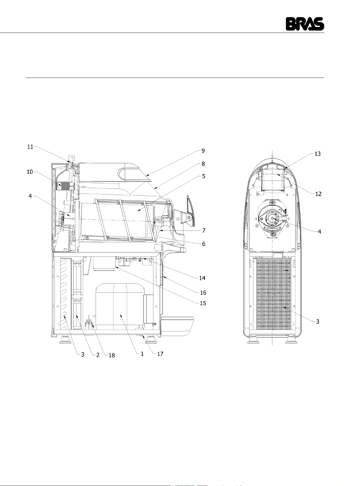
1 APPLIANCE’S DESCRIPTION
This dispenser is designed for the production of iced or frozen drinks such as crushed ice drinks, ice creams and sorbets. The lower
half of the dispenser contains the cooling system, which consists of a compressor (1), a condenser (3), the related fans (2) and a
solenoid valve to open and close the cooling circuit. The lower half of the dispenser also contains the circuit boards designed to
control operation (14) and (16) and the power supply transformer (15) for both the circuit boards and the geared motor to drive the
mixers.
The upper half of the dispenser contains the transparent tank (8) designed for the food product, which in turn contains the mixer (7)
and the evaporator cylinder (5) which is the unit that chills the product. In addition, the rear of the dispenser houses the electric motor
(4) and the geared motor which drives the mixer, the tank defrosting fan (10) and any LED lamps.
figure 1
The dispenser also features a main ON/OFF switch situated on the left-hand side of the frame underside. In addition, each tank is
fitted with a control panel, situated under the dispenser tap, the functions of which are described below.
BCREAM HD 1/2/3
The model BCream HD, in production starting from year 2014, has the following differences from the previous model:
More powerful mixing system
Cup sensor for ease of dispensing
Graphic display showing a larger number of messages
Improved software for better product handling
Timer for operation programming
29
B-Cream & B-cream HD
ENGLISH
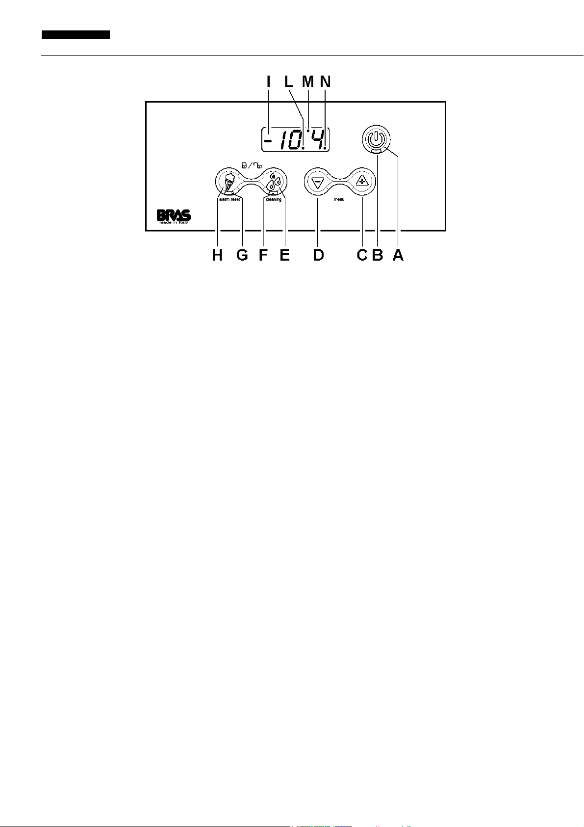
BCREAM 1/2/3
figura 2
(A) ON / OFF key (on dispensers with more than one tank, this key is only present on the right-hand tank control panel): press
it for one second to turn the dispenser on or off. When the appliance is in use, press it briefly to turn the lights on or off, where
featured.
(B) Status indicator light (on dispensers with more than one tank, this indicator light is only present on the right-hand tank control
panel): if it is on, this means the main switch situated under the dispenser is turned on and the appliance is powered and
ready for use.
(C) Plus key: in ice cream production mode, this key increases the density of the product.
(D) Minus key: in ice cream production mode, this key decreases the density of the product.
(E) Conservation key: allows you to select the product conservation operating mode. On dispensers with more than one tank, if
you hold this key down while the tank is in product conservation mode, the corresponding tank will be turned off. If you press
it for two seconds, the dispenser switches to "Cleaning" mode: the mixer is on but the cooling is off.
(F) Conservation indicator light: flashing light => product conservation mode selected, conservation temperature not reached.
Indicator light permanently on => product conservation mode selected, temperature reached.
(G) Ice cream production indicator light: flashing light => ice cream production mode selected, product not ready. Indicator light
permanently on => ice cream production mode selected, product ready.
(H) Ice cream production key: allows you to select the ice cream production operating mode. On dispensers with more than one
tank, if you hold this key down while the tank is in ice cream production mode, the corresponding tank will be turned off.
(I) Product temperature.
(L) Decimal point.
(M) Solenoid valve indicator light: indicator light on => solenoid valve open. Indicator light off => solenoid valve closed. Flashing
indicator light => solenoid valve opening delay under way (factory set to 15 seconds).
(N) Compressor indicator light: indicator light on => compressor on. Indicator light off => compressor off. Flashing indicator light
=> compressor start delay under way (factory set to 120 seconds).
30
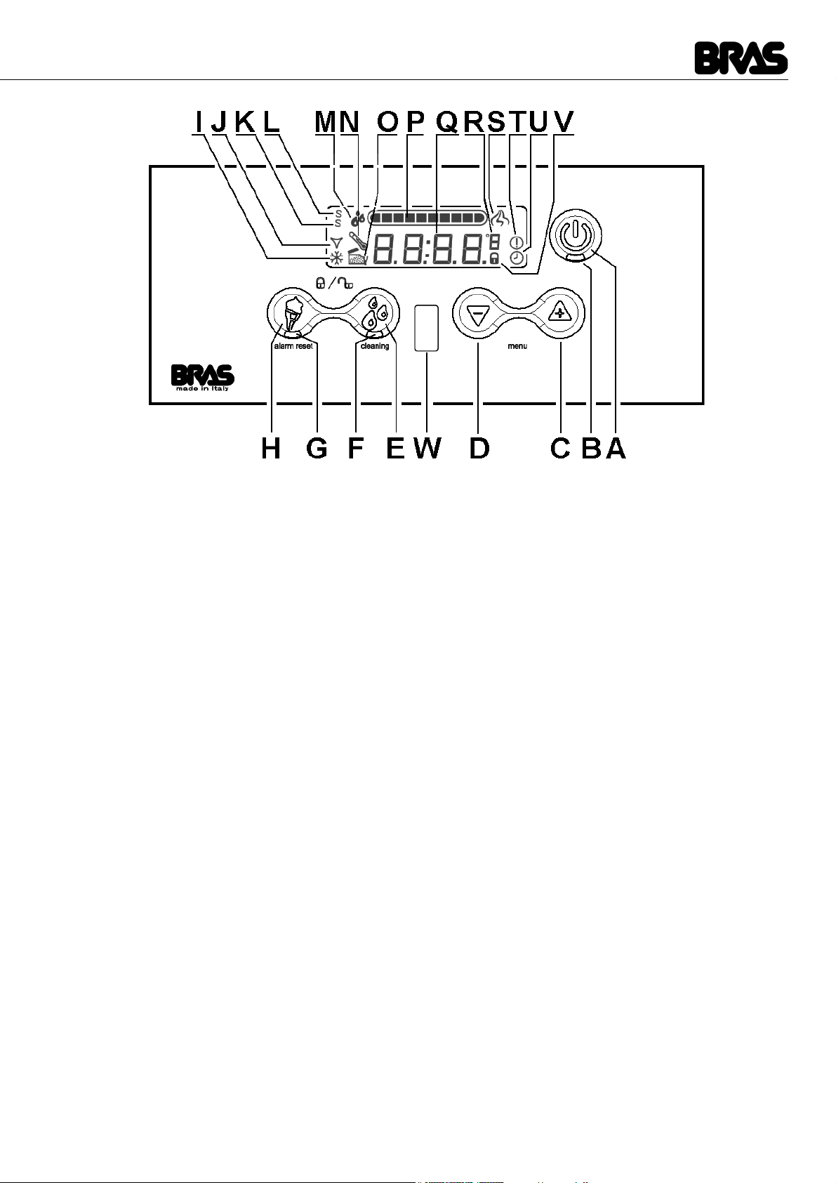
BCREAM HD 1/2/3
figura 3
(A) ON / OFF key (on dispensers with more than one tank, this key is only present on the right-hand tank control panel): press
it for one second to turn the dispenser on or off. When the appliance is in use, press it briefly to turn the lights on or off, where
featured.
(B) Status indicator light (on dispensers with more than one tank, this indicator light is only present on the right-hand tank control
panel): if it is on, this means the main switch situated under the dispenser is turned on and the appliance is powered and
ready for use.
(C) Plus key: in ice cream production mode, this key increases the density of the product.
(D) Minus key: in ice cream production mode, this key decreases the density of the product.
(E) Conservation key: allows you to select the product conservation operating mode. On dispensers with more than one tank, if
you hold this key down while the tank is in product conservation mode, the corresponding tank will be turned off. If you press
it for two seconds, the dispenser switches to "Cleaning" mode: the mixer is on but the cooling is off.
(F) Conservation indicator light: flashing light => product conservation mode selected, conservation temperature not reached.
Indicator light permanently on => product conservation mode selected, temperature reached.
(G) Ice cream production indicator light: flashing light => ice cream production mode selected, product not ready. Indicator light
permanently on => ice cream production mode selected, product ready.
(H) Ice cream production key: allows you to select the ice cream production operating mode. On dispensers with more than one
tank, if you hold this key down while the tank is in ice cream production mode, the corresponding tank will be turned off.
(I) Compressor icon: icon ON => compressor ON. Icon OFF => compressor OFF. Icon blinking => compressor OFF delay in
progress (factory default PA14=180 seconds)
(J) Solenoid valve icon: icon ON => solenoid valve open. Icon OFF => solenoid valve closed . Icon blinking => solenoid valve
closed time in progress (factory default PA15=20 seconds)
(K) Service Mode Icon: icon ON => the machine has been started in Service Mode (main switch + key A) and it is possible to set
the working parameters.
(L) Super Service Mode Icon: this icon and icon (K) ON => the machine has been started in Super Service Mode (main switch
+ key A) and it is possible to set the factory parameters.
(M) Liquid product icon: actualy not implemented
(N) Temperature Alarm Icon: icon ON => the temperature of the product raised over the warning temperature (PA21= 4°C set
as factory default)
(O) Open top cover icon: icon ON => the top cover is open and the machine can’t work (in case of machines with multiple con-
tainers, only the one with the open top cover is stopped).
(P) Viscosity setting: graphical representation of the set value of the viscosity of the product
(Q) Temperature of the product into the bowl
(R) Temperature scale: temperature scale as set by parameter PA08
(S) Dispensing Icon: icon ON => the cup sensor has detected the presence of a cup and the speed of rotation of the mixer is
increased to the value of the parameter PA03
(T) Alarm Icon: icon ON => an alarm is active
31
B-Cream & B-cream HD
ENGLISH
(U) Defrost timer Icon: icon ON => Defrost timer active, the switching between conservation and ice cream mode is operated
automatically following the timer settings and can’t be performed manually.
(V) Locked Keyboard Icon: icon ON => keyboard is locked and it is impossible to adjust the machine unless the keyboard is un-
locked (key E + key H pressed for 2 seconds)
(W) Cup sensor: the cup sensor detects the presence of a cup up to a distance of approx 15 cm and increases the rotation speed
of the mixer to the value of the parameter PA03
IMPORTANT
On dispensers with more than one tank, the ON/OFF key (A) and related indicator light (B) are only present on the control panel of the right-hand tank but their
operation affects the entire appliance. Therefore pressing key (A) will turn all the
tanks on or off and, where featured, it will also turn all the lights on or off.
IMPORTANT
On dispensers with more than one tank, should you wish to turn off a single
tank, you will have to press the key for the operating mode currently in use on
the related control panel. Both the cooling and the mixer will stop and the corresponding display will show the message: OFF.
2 OPERATING PRINCIPLE
The operating principle of this dispenser is based on cooling and concurrently mixing the product inside the transparent tank. When
the product reaches negative temperatures, it begins to freeze, thereby increasing in density and therefore the effort required by the
geared motor to mix it. Using the electricity consumption value, the electronic control system is able to determine this effort and when
it reaches a set level, the solenoid valve is closed, thereby shutting off the supply of refrigerant gas to the evaporator cylinder. Since
the product is no longer cooled, it tends to melt, thereby decreasing in density and therefore the effort required by the geared motor
to mix it. When the effort drops below a set level, the solenoid valve re-opens, the refrigerant gas resumes its passage through the
evaporator cylinder and the product cools down and increases in density again. This regulation system ensures the density of the
product is kept at a set level.
Setting the density of the product to between 1 and 10 makes it possible to obtain a product with the required level of density. By
default, the maximum setting, i.e. when the density is set to 10, corresponds to consumption of electrical power of 65 watts, which
can be increased to 100 watts by starting up the machine in Service Mode and adjusting the PA02 parameter (see relative paragraph). Each density setting value corresponds to 1/10 of the value of the PA02 parameter. In addition to this, the machine checks
that the product temperature does not drop below a minimum operating temperature defined by the PA03 parameter, whose default
setting is -14 °C. This setting is useful to prevent the remaining product gradually reaching ever lower temperatures as the container
is progressively drained.
Again starting up the machine in Service Mode, it is also possible to set the rotation speed of the mixer when the product is being
prepared (PA03 parameter), when the product is ready (PA04 parameter) and when the machine is in product storage mode (PA05
parameter).
IMPORTANT
When the ice cream production operating mode is selected, the compressor is
always on. When the dispenser is turned on, after the 120-second safety delay,
the compressor starts up and always stays on.
When the product conservation operating mode is selected, the compressor is
only on if at least one of the solenoid valves is open and therefore if at least one
of the tanks requires cooling. Every time the compressor is turned off, a safety
time lapse of 120 seconds must pass before it can be restarted.
As well as the operating modes described in the Instruction Manual, the dispenser may be started up in other modes which can be
used for technical support. These modes are summarised in the table below:
Mode Description Activation key
Operation Parameters Mode In this mode, the machine functions normally but it is pos-
Production Parameters Mode In this mode, the machine functions normally but it is pos-
sible to modify the Operation Parameters.
Master switch + key A
Master switch + key A + key H
sible to modify all Parameters, concerning both Operation
and Production.
32

Test Mode In this mode, the machine does not function and it is possi-
ble to manually activate individual components to check
that they are functioning correctly.
Production Test Mode In this mode, the machine does not function and it is possi-
ble to activate individual components in sequence to check
that they are functioning correctly.
Master switch + key E
Master switch + key H
3 SERVICE MODE – ADJUSTING THE OPERATION PARAMETERS
By switching on the dispenser using the master switch and holding down key A simultaneously, the machine can be started up in
service mode and make adjusting the Operation Parameters. The dispenser will function normally, but it will be possible to modify
the operation parameters and any modifications carried out will be stored in the memory for the next time the dispenser is switched
on in normal mode.
When the machine is in use, to adjust the operation parameters, hold down keys C and D simultaneously. The display will show the
code PA01 to indicate the first parameter which may be modified. Pressing keys C and D enables the selection of the parameter to
be modified. Pressing key A will then make it possible to activate the modification of the chosen parameter. The display will show
the current value of the parameter. This value can be modified using keys C and D. Pressing key A once more or waiting three seconds without pressing any keys confirms the new value and the display will return to the list of parameters. To exit the parameter
adjustment, hold down keys C and D simultaneously or do not press any key for three seconds.
IMPORTANT
On dispensers with more than one tank, the operating parameters, from PA01 to
PA10, must be set separately for each tank.
LIST OF PRODUCTION PARAMETERS B-CREAM 1/2/3
NAME DESCRIPTION ADJUSTMENT INTERVAL DEFAULT VALUE
PA01 Minimum temperature in Ice Cream Production Mode: This is the
minimum possible temperature of the product when the density is
adjusted to a value of 10.
PA02 Maximum density in Ice Cream Production Mode: this is the ab-
sorption value of the motor corresponding to the adjustment of the
density to a value of 10.
PA03 Motor rotation speed in Ice Cream Production Mode with an unfi-
nished product.
PA04 Motor rotation speed in Ice Cream Production Mode with a finished
product.
PA05 Motor rotation speed in Conservation Mode. 500…6000 giri/min 1000
PA06 Temperature produced in Conservation Mode. - 25 ÷ + 10 °C 2 °C
PA07 Lock Keypad. 0 / 1 / 2 0
PA08 Scale representation of temperature. C…F C
PA09 Firmware version display circuit board. Visualisation only
PA10 Firmware version power circuit board. Visualisation only
LIST OF PRODUCTION PARAMETERS B-CREAM HD 1/2/3
NAME DESCRIPTION ADJUSTMENT INTERVAL DEFAULT VALUE
PA01 Minimum temperature in Ice Cream Production Mode: This is the
minimum possible temperature of the product when the density is
adjusted to a value of 10.
PA02 Maximum density in Ice Cream Production Mode: this is the ab-
sorption value of the motor corresponding to the adjustment of the
density to a value of 10.
PA03 Motor rotation speed in Ice Cream Production Mode with an unfi-
nished product.
PA04 Motor rotation speed in Ice Cream Production Mode with a finished
product.
PA05 Motor rotation speed in Conservation Mode. 1000…6000 giri/min 1000
PA06 Temperature produced in Conservation Mode. - 5 ÷ + 10 °C 2 °C
0...-18 °C -14
0...100 W 60
500…6000 giri/min 3500
500…6000 giri/min 3500
0...-18 °C -14
45...90 W 75
2000…6000 giri/min 4000
2000…6000 giri/min 2000
33
B-Cream & B-cream HD
ENGLISH
PA07 Lock Keypad. 0 / 1 / 2 0
PA08 Scale representation of temperature. C…F C
PA09 Firmware version display circuit board.
2015 version : enabling defrost timer.
PA10 Firmware version power circuit board.
2015 version : counter machine life
4 SUPER SERVICE MODE – ADJUSTING THE MANUFACTORY PARAMETERS
By switching on the dispenser using the master switch and holding down keys A and H simultaneously, the machine can be started
up in Super Service Mode and make adjusting the manufactory parameters. The dispenser will function normally, but it will be possible to modify the production parameters and any modifications carried out will be stored in the memory for the next time the dispenser is switched on in normal mode.
For information on how to adjust the production parameters, please refer to the instructions for the operation parameters.
IMPORTANT
Incorrect adjustment of the Production Parameters may compromise the operation of the machine.
Visualisation only
ON / OFF OFF
Visualisation only
Days 0
IMPORTANT
Distributors in more containers from the factory parameters PA11 to PA 27 are
common to all the distributor and therefore can only be adjusted by the control
panel on the right container.
LIST OF PRODUCTION PARAMETERS B-CREAM 1/2/3
NAME DESCRIPTION ADJUSTMENT INTERVAL DEFAULT VALUE
PA11 Ice Cream Production Mode Density 1…10 8
PA12 Ice Cream Production Mode Density Hysteresis 0...4,0 0,2
PA13 Ice Cream Production Mode Temperature Hysteresis 0…5 °C 0,5
PA14 Compressor lockout time OFF 0…600 s 180
PA15 Electrovalve lockout time OFF 0…600 s 180
PA16 Time for which the density must remain above the reference value 0…60 s 1
PA17 Conservation Mode Temperature Hysteresis 0…5 °C 0,5
PA18 Maximum motor absorption 0…100 W 90
PA19 Motor cooling time 0…600 s 90
PA20 Motor protection intervention delay 0…60 s 5
PA21 Product conservation alarm temperature 0…10 °C 4
PA22 Tap sensor entry activation ON…OFF OFF
PA23 Temperature probe offset ? 0
PA24 Number of motor poles 0…1000 300
PA25 Motor control proportional P constant 0…1000 4
PA26 Motor control integral I constant 0…1000 0
PA27 Motor control derivative D constant YES…NO NO
LIST OF PRODUCTION PARAMETERS B-CREAM HD 1/2/3
NAME DESCRIPTION ADJUSTMENT INTERVAL DEFAULT VALUE
PA11 Ice Cream Production Mode Density 1…10 8
PA12 Ice Cream Production Mode Density Hysteresis 0...4,0 0,2
PA13 Ice Cream Production Mode Temperature Hysteresis 0…5 °C 0,5
PA14 Compressor lockout time OFF 0…600 s 180
34

PA15 Electrovalve lockout time OFF 0…600 s
PA16 Time for which the density must remain above the reference value 0…60 s 1
PA17 Conservation Mode Temperature Hysteresis 0…5 °C 0,5
PA18 Maximum motor absorption YES…NO 120
PA19 Motor cooling time 0…600 s 90
PA20 Motor protection intervention delay 0…60 s 5
PA21 Product conservation alarm temperature 0…10 °C 4
PA22 Tap sensor entry activation ON / OFF OFF
PA23 Available for future implementations
2015 version : locking density
PA24 Mixer rotation inversion when in conservation mode YES…NO YES
PA25 Mixer rotation inversion delay 0…3600 900
PA26 Minimum time of rotation speed increasing when cup is detected 0…60 10
PA27 Reset of the parameters to default values YES…NO NO
0...25
YES / NO
20
0
NO
5 PARAMETER RESET
To reset the parameters to the default values it is necessary to switch on the machine, using the main switch located under the unit,
holding down keys C and D simultaneosly, selecting YES value pressing key C and then confirming it, pressing key A.
It is also possible to reset the parameters to the default values starting the machine in Super Service Mode, selecting parameters
PA27, selecting YES value pressing key C and then confirming it, pressing key A.
6 FUNCTIONAL TEST OF THE MACHINE
The following procedure allows to test the complete functionality of the unit:
1 Switch On the machine.
2 If in Standby set the machine in Working Mode.
3 Set all the bowls in Ice Cream Mode: the gear motors must turn regularly. The icon J flashes on the right display. The icons I
flash on all the displays.
4 After 15 seconds, when the time set by parameter PA15 is expired (delay timer of the solenoid valves, factory default 15 sec.)
the solenoid valves open (the sound "click" must be heard one time for each bowl in a short time). The icon J, on all the display,
stop flashing becoming still.
5 After 180 seconds, when the time set by parameter PA14 is expired (delay timer of the compressor, factory default 180 sec) the
compressor and the fan motor start. Now the cooling system of the machine is working and after some ten of seconds the
evaporators must begin to freeze in the front lower part. The icon I, on the right display, stops flashing becoming still.
6 If it is possible to complete this procedure with success it means that the machine works properly.
This test takes approx. 5 minutes and allows to verify the proper working of the gear motors, of the compressor, of the fan motor, of
the solenoid valves and of the electronic boards all together.
The only thing that this procedure can't allow to verify is the efficiency of the cooling system which can be reduced for example due
to a leak of refrigerant gas. In order to execute such a check, a test with product, 90 minutes long, is required.
7 PROTECTION AGAINST EXCESSIVE DENSITY
In the case of excessive product density, in order to avoid damage to the dispenser, both the freezer and the mixer will be stopped
for three minutes and one of the following messages will appear on the display: “AL03”, “AL06” or “AL08”. After three minutes, both
mixing and freezing will be reactivated and the previous density setting will be decreased by one level.
To reset the alarm message and return to the fixed display, hold down the B key for three seconds.
From serial number 1184, with the introduction of firmware versions 025 and 018, the alarm display has been replaced by the symbol
---- shown on the display.
The alarm display is possible in Service Mode or Super Service (see paragraph 3 and 4) or, during normal operation, by simultaneously pressing the + and -.
8 ALARMS
The table below summarises the machine’s alarm codes:
Code Title alarm Note
COV Cover opened It warns the operator that the machine can not operate if the
AL02 Product temperature alarm This alarm stops the operation of the machine
lid is not closed
35

B-Cream & B-cream HD
ENGLISH
AL03 Excessive motor absorption Alarm displayed when the machine is operating in Service
AL04 Temperature probe damaged This alarm stops the operation of the machine
AL05 Circuit board transmission error This alarm stops the operation of the machine
AL06 Unplanned motor stop Alarm displayed when the machine is operating in Service
AL07 24V power supply missing This alarm stops the operation of the machine
AL08 Excess current, hardware protection intervention Alarm displayed when the machine is operating in Service
AL09 Error Hall probes This alarm stops the operation of the machine
AL10 Lack of communication between master and slave card 1 This alarm stops the operation of the machine
AL11 Lack of communication between master and slave card 2 This alarm stops the operation of the machine
AL12 Alarm low voltage motor This alarm don’t stops the operation of the machine
AL13 System clock out of order System clock out of order. The machine can work but the de-
AL14 Clock battery out of order Clock battery expired or out of order. The machine can work
If one of these alarm codes appears on the display, please refer to Appendix 1: Possible Problems and their Solutions.
Mode Service Mode or Super
Mode Service Mode or Super
Mode Service Mode or Super
frost timer can’t be used.
but current time is reset when the machine is powered off.
9 FIRMWARE VERSIONS CHRONOLOGY
Control display
Version Notes
0.22 First production version.
0.23 Updates 2013.
1.01 Updates 2014.
1.08 Updates 2015.
Power board
Version Notes
0.06 First production version.
0.10 Updates 2013.
0.27 Updates 2014.
0.35 Updates 2015.
First produtcion version with LCD display.
Compatible version with new LCD display.
36
 Loading...