


Original Instructions
100-412-199 - REV. 07
DCX F-DP
Power Supply
Operating Manual
Branson Ultrasonics Corporation
41 Eagle Road
Danbury, CT 06813-1961 USA
(203) 796-0400
http://www.bransonultrasonics.com

Manual Change Information
At Branson, we strive to maintain our position as the leader in ultrasonics plastics joining,
metal welding, cleaning and related technologies by continually improving our circuits and
components in our equipment. These improvements are incorporated as soon as they are
developed and thoroughly tested.
Information concerning any improvements will be added to the appropriate technical
documentation at its next revision and printing. Therefore, when requesting service
assistance for specific units, note the Revision information found on the cover of this
document, and refer to the printing date which appears at the bottom of this page.
Copyright and Trademark Notice
Copyright © 2015 Branson Ultrasonics Corporation. All rights reserved. Contents of this publication may not be
reproduced in any form without the written permission of Branson Ultrasonics Corporation.
Mylar is a registered trademark of DuPont Teijin Films.
Loctite is a registered trademark of Loctite Corporation.
WD-40 is a registered trademark of WD-40 Company.
Windows 7, Windows Vista, and Windows XP are registered trademarks of Microsoft Corporation
Other trademarks and service marks mentioned herein are held by their respective
owners.
ii 100-412-199 REV. 07

Foreword
Congratulations on your choice of a Branson Ultrasonics Corporation system!
The Branson DCX Power Supply F-DP system is process equipment for the joining of
plastic parts using ultrasonic energy. It is the newest generation of product using this
sophisticated technology for a variety of customer applications. This Operating Manual is
part of the documentation set for this system, and should be kept with the equipment.
Thank you for choosing Branson!
Introduction
This manual is arranged into several structured chapters which will help you find the
information you may need to know to safely handle, install, set up, program, operate,
and/or maintain this product. Please refer to the Table Of Contents and/or the Index of
this manual to find the information you may be looking for. In the event you require
additional assistance or information, please contact our Product Support department (see
1.4 How to Contact Branson for information on how to contact them) or y our local Branson
representative.
100-412-199 REV. 07 iii

iv 100-412-199 REV. 07

Table Of Contents
Chapter 1:Safety and Support
1.1 Safety Requirements and Warnings . . . . . . . . . . . . . . . . . . . . . . . . . . . . . . . . . . . 2
1.2 General Precautions. . . . . . . . . . . . . . . . . . . . . . . . . . . . . . . . . . . . . . . . . . . . . . 4
1.3 Warranty Statement, Disclaimer . . . . . . . . . . . . . . . . . . . . . . . . . . . . . . . . . . . . . 6
1.4 How to Contact Branson. . . . . . . . . . . . . . . . . . . . . . . . . . . . . . . . . . . . . . . . . . . 8
1.5 Returning Equipment for Repair . . . . . . . . . . . . . . . . . . . . . . . . . . . . . . . . . . . . . 9
1.6 Obtaining Replacement Parts . . . . . . . . . . . . . . . . . . . . . . . . . . . . . . . . . . . . . . .12
Chapter 2:Introduction
2.1 Models Covered. . . . . . . . . . . . . . . . . . . . . . . . . . . . . . . . . . . . . . . . . . . . . . . . .14
2.2 Compatibility with other Branson Products . . . . . . . . . . . . . . . . . . . . . . . . . . . . . .16
2.3 Features. . . . . . . . . . . . . . . . . . . . . . . . . . . . . . . . . . . . . . . . . . . . . . . . . . . . . .17
2.4 Controls and Indicators . . . . . . . . . . . . . . . . . . . . . . . . . . . . . . . . . . . . . . . . . . .19
2.5 Welding Systems. . . . . . . . . . . . . . . . . . . . . . . . . . . . . . . . . . . . . . . . . . . . . . . .25
2.6 Glossary of Terms . . . . . . . . . . . . . . . . . . . . . . . . . . . . . . . . . . . . . . . . . . . . . . .26
Chapter 3:Delivery and Handling
3.1 Shipping and Handling . . . . . . . . . . . . . . . . . . . . . . . . . . . . . . . . . . . . . . . . . . . .30
3.2 Receiving . . . . . . . . . . . . . . . . . . . . . . . . . . . . . . . . . . . . . . . . . . . . . . . . . . . . .31
3.3 Unpacking the Power Supply. . . . . . . . . . . . . . . . . . . . . . . . . . . . . . . . . . . . . . . .32
3.4 Take Inventory of Small Parts. . . . . . . . . . . . . . . . . . . . . . . . . . . . . . . . . . . . . . .33
3.5 Returning Equipment . . . . . . . . . . . . . . . . . . . . . . . . . . . . . . . . . . . . . . . . . . . . .34
Chapter 4:Technical Specifications
4.1 Technical Specifications . . . . . . . . . . . . . . . . . . . . . . . . . . . . . . . . . . . . . . . . . . .36
4.2 Physical Description. . . . . . . . . . . . . . . . . . . . . . . . . . . . . . . . . . . . . . . . . . . . . .38
4.3 Declaration of Conformity. . . . . . . . . . . . . . . . . . . . . . . . . . . . . . . . . . . . . . . . . .39
4.4 PROFIBUS Certificate . . . . . . . . . . . . . . . . . . . . . . . . . . . . . . . . . . . . . . . . . . . . .40
Chapter 5:Installation and Setup
5.1 About Installation . . . . . . . . . . . . . . . . . . . . . . . . . . . . . . . . . . . . . . . . . . . . . . .44
5.2 Installation Requirements. . . . . . . . . . . . . . . . . . . . . . . . . . . . . . . . . . . . . . . . . .45
5.3 Installation Steps . . . . . . . . . . . . . . . . . . . . . . . . . . . . . . . . . . . . . . . . . . . . . . .51
5.4 Electrical Connections . . . . . . . . . . . . . . . . . . . . . . . . . . . . . . . . . . . . . . . . . . . .54
5.5 Power Supply Setup. . . . . . . . . . . . . . . . . . . . . . . . . . . . . . . . . . . . . . . . . . . . . .69
5.6 Assembling the Acoustic Stack . . . . . . . . . . . . . . . . . . . . . . . . . . . . . . . . . . . . . .70
5.7 Converter Cooling . . . . . . . . . . . . . . . . . . . . . . . . . . . . . . . . . . . . . . . . . . . . . . .75
5.8 Testing the Installation . . . . . . . . . . . . . . . . . . . . . . . . . . . . . . . . . . . . . . . . . . .77
5.9 Still Need Help?. . . . . . . . . . . . . . . . . . . . . . . . . . . . . . . . . . . . . . . . . . . . . . . . .78
Chapter 6:Converters and Boosters
6.1 Converters and Boosters . . . . . . . . . . . . . . . . . . . . . . . . . . . . . . . . . . . . . . . . . .80
Chapter 7:Operation
7.1 Setting Primary Parameters . . . . . . . . . . . . . . . . . . . . . . . . . . . . . . . . . . . . . . . .92
7.2 Setting the Amplitude . . . . . . . . . . . . . . . . . . . . . . . . . . . . . . . . . . . . . . . . . . .102
7.3 Resetting the Power Supply Alarms . . . . . . . . . . . . . . . . . . . . . . . . . . . . . . . . . .104
7.4 Configuring the Power Supply Registers . . . . . . . . . . . . . . . . . . . . . . . . . . . . . . .105
7.5 LCD Bar-Graph . . . . . . . . . . . . . . . . . . . . . . . . . . . . . . . . . . . . . . . . . . . . . . . . 109
100-412-199 REV. 07 iii

7.6 Ultrasonics Test Procedure. . . . . . . . . . . . . . . . . . . . . . . . . . . . . . . . . . . . . . . . 112
7.7 Using the I/O Connections . . . . . . . . . . . . . . . . . . . . . . . . . . . . . . . . . . . . . . . . 114
Chapter 8:PROFIBUS DP Operation
8.1 PROFIBUS DP. . . . . . . . . . . . . . . . . . . . . . . . . . . . . . . . . . . . . . . . . . . . . . . . . 116
8.2 Configuration . . . . . . . . . . . . . . . . . . . . . . . . . . . . . . . . . . . . . . . . . . . . . . . . . 119
8.3 Implicit Messaging . . . . . . . . . . . . . . . . . . . . . . . . . . . . . . . . . . . . . . . . . . . . . 128
Chapter 9:Maintenance
9.1 General Maintenance Considerations. . . . . . . . . . . . . . . . . . . . . . . . . . . . . . . . . 142
9.2 DCX Power Supply F-DP Preventive Maintenance . . . . . . . . . . . . . . . . . . . . . . . . 144
9.3 Recommended Spare Stock . . . . . . . . . . . . . . . . . . . . . . . . . . . . . . . . . . . . . . . 149
9.4 Circuit Diagram . . . . . . . . . . . . . . . . . . . . . . . . . . . . . . . . . . . . . . . . . . . . . . . 154
9.5 Troubleshooting . . . . . . . . . . . . . . . . . . . . . . . . . . . . . . . . . . . . . . . . . . . . . . . 155
9.6 Cold Start Procedure. . . . . . . . . . . . . . . . . . . . . . . . . . . . . . . . . . . . . . . . . . . . 158
Appendix A:Alarms
A.1 Overload Alarms (Group 0) . . . . . . . . . . . . . . . . . . . . . . . . . . . . . . . . . . . . . . . 160
A.2 Cutoff Alarms (Group 1) . . . . . . . . . . . . . . . . . . . . . . . . . . . . . . . . . . . . . . . . . 162
A.3 Setup Alarms (Group 2) . . . . . . . . . . . . . . . . . . . . . . . . . . . . . . . . . . . . . . . . . 163
A.4 Cycle Modified Alarms (Group 3) . . . . . . . . . . . . . . . . . . . . . . . . . . . . . . . . . . . 164
A.5 Warning Alarms (Group 4). . . . . . . . . . . . . . . . . . . . . . . . . . . . . . . . . . . . . . . . 165
A.6 Limit Alarms (Group 5) . . . . . . . . . . . . . . . . . . . . . . . . . . . . . . . . . . . . . . . . . . 166
A.7 Equipment Failure Alarms (Group 6). . . . . . . . . . . . . . . . . . . . . . . . . . . . . . . . . 167
A.8 No Cycle Alarms (Group 7) . . . . . . . . . . . . . . . . . . . . . . . . . . . . . . . . . . . . . . . 169
A.9 Communication Failure Alarms (Group 8) . . . . . . . . . . . . . . . . . . . . . . . . . . . . . 170
A.10 Hardware Alarms (Group A). . . . . . . . . . . . . . . . . . . . . . . . . . . . . . . . . . . . . . . 171
A.11 Non-Cycle Overload Alarms (Group B). . . . . . . . . . . . . . . . . . . . . . . . . . . . . . . . 172
Appendix B:Communication Channel Commands
B.1 Weld Parameters . . . . . . . . . . . . . . . . . . . . . . . . . . . . . . . . . . . . . . . . . . . . . . 176
B.2 Seek Stack Parameters . . . . . . . . . . . . . . . . . . . . . . . . . . . . . . . . . . . . . . . . . . 180
B.3 Test Stack Parameters . . . . . . . . . . . . . . . . . . . . . . . . . . . . . . . . . . . . . . . . . . 181
B.4 Common Stack Parameters . . . . . . . . . . . . . . . . . . . . . . . . . . . . . . . . . . . . . . . 182
B.5 Alarm Commands. . . . . . . . . . . . . . . . . . . . . . . . . . . . . . . . . . . . . . . . . . . . . . 183
B.6 Weld Parameter Status . . . . . . . . . . . . . . . . . . . . . . . . . . . . . . . . . . . . . . . . . . 184
B.7 Weld Status Commands . . . . . . . . . . . . . . . . . . . . . . . . . . . . . . . . . . . . . . . . . 186
B.8 Seek Parameter Status . . . . . . . . . . . . . . . . . . . . . . . . . . . . . . . . . . . . . . . . . . 187
B.9 Seek Stack Commands . . . . . . . . . . . . . . . . . . . . . . . . . . . . . . . . . . . . . . . . . . 188
B.10 Test Parameter Status. . . . . . . . . . . . . . . . . . . . . . . . . . . . . . . . . . . . . . . . . . . 189
B.11 Test Stack Commands. . . . . . . . . . . . . . . . . . . . . . . . . . . . . . . . . . . . . . . . . . . 190
B.12 Scan Parameter Status . . . . . . . . . . . . . . . . . . . . . . . . . . . . . . . . . . . . . . . . . . 191
B.13 Scan Stack Commands . . . . . . . . . . . . . . . . . . . . . . . . . . . . . . . . . . . . . . . . . . 192
B.14 Process Data Channels . . . . . . . . . . . . . . . . . . . . . . . . . . . . . . . . . . . . . . . . . . 193
B.15 Communication Channel . . . . . . . . . . . . . . . . . . . . . . . . . . . . . . . . . . . . . . . . . 194
B.16 Token Access . . . . . . . . . . . . . . . . . . . . . . . . . . . . . . . . . . . . . . . . . . . . . . . . . 195
B.17 Version, System, & RTC Information. . . . . . . . . . . . . . . . . . . . . . . . . . . . . . . . . 196
B.18 System Configuration Parameters. . . . . . . . . . . . . . . . . . . . . . . . . . . . . . . . . . . 197
Appendix C:Timing Diagrams
C.1 Timing Diagrams . . . . . . . . . . . . . . . . . . . . . . . . . . . . . . . . . . . . . . . . . . . . . . 200
Appendix D:Signal Diagrams
D.1 Signal Diagrams . . . . . . . . . . . . . . . . . . . . . . . . . . . . . . . . . . . . . . . . . . . . . . . 208
iv 100-412-199 REV. 07

List Of Figures
Chapter 1:Safety and Support
Figure 1.1 Safety-related Labels found on the DCX Power Supply F-DP . . . . . . . . . . . . . . . . . . 3
Chapter 2:Introduction
Figure 2.1 The DCX Power Supply F-DP (Horizontal) . . . . . . . . . . . . . . . . . . . . . . . . . . . . . . .14
Figure 2.2 The DCX Power Supply F-DP (Vertical). . . . . . . . . . . . . . . . . . . . . . . . . . . . . . . . .15
Figure 2.3 DCX Power Supply F-DP Front Panel Controls and Indicators . . . . . . . . . . . . . . . . .19
Figure 2.4 LCD Description . . . . . . . . . . . . . . . . . . . . . . . . . . . . . . . . . . . . . . . . . . . . . . . .21
Figure 2.5 DCX Power Supply F-DP Back Panel (Horizontal) . . . . . . . . . . . . . . . . . . . . . . . . . .24
Figure 2.6 DCX Power Supply F-DP Bottom Panel (Vertical) . . . . . . . . . . . . . . . . . . . . . . . . . .24
Chapter 3:Delivery and Handling
Chapter 4:Technical Specifications
Figure 4.1 Declaration of Conformity. . . . . . . . . . . . . . . . . . . . . . . . . . . . . . . . . . . . . . . . . .39
Figure 4.2 PROFIBUS Certificate . . . . . . . . . . . . . . . . . . . . . . . . . . . . . . . . . . . . . . . . . . . . .40
Figure 4.3 Association Trademark. . . . . . . . . . . . . . . . . . . . . . . . . . . . . . . . . . . . . . . . . . . .41
Figure 4.4 Technology Trademarks . . . . . . . . . . . . . . . . . . . . . . . . . . . . . . . . . . . . . . . . . . .41
Figure 4.5 Certification Trademark . . . . . . . . . . . . . . . . . . . . . . . . . . . . . . . . . . . . . . . . . . .41
Figure 4.6 Certified by PI Trademark. . . . . . . . . . . . . . . . . . . . . . . . . . . . . . . . . . . . . . . . . .41
Chapter 5:Installation and Setup
Figure 5.1 DCX Power Supply F-DP Benchtop Dimensional Drawing . . . . . . . . . . . . . . . . . . . .46
Figure 5.2 DCX Power Supply F-DP Vertical Mount Dimensional Drawing (400 W, 750 W and 800 W)
47
Figure 5.3 DCX Power Supply F-DP Vertical Mount Dimensional Drawing (1.25 kW and 1.5 kW) 48
Figure 5.4 DCX Power Supply F-DP Vertical Mount Dimensional Drawing (2.5 kW and 4 kW) . .49
Figure 5.5 LCD Viewing Angle . . . . . . . . . . . . . . . . . . . . . . . . . . . . . . . . . . . . . . . . . . . . . .53
Figure 5.6 DCX Power Supply F-DP Connections (Horizontal Model) . . . . . . . . . . . . . . . . . . . .54
Figure 5.7 DCX Power Supply F-DP Connections (Vertical Model) . . . . . . . . . . . . . . . . . . . . . .55
Figure 5.8 User I/O Cable Identification and Wire Color Diagram . . . . . . . . . . . . . . . . . . . . . .56
Figure 5.9 Typical Digital I/O Wiring Examples . . . . . . . . . . . . . . . . . . . . . . . . . . . . . . . . . . .66
Figure 5.10 Typical Analog I/O Wiring Examples. . . . . . . . . . . . . . . . . . . . . . . . . . . . . . . . . . .66
Figure 5.11 RF Cable Connection . . . . . . . . . . . . . . . . . . . . . . . . . . . . . . . . . . . . . . . . . . . . .67
Figure 5.12 Assembling the Acoustic Stack . . . . . . . . . . . . . . . . . . . . . . . . . . . . . . . . . . . . . .71
Figure 5.13 Connecting Tip to Horn . . . . . . . . . . . . . . . . . . . . . . . . . . . . . . . . . . . . . . . . . . .74
Chapter 6:Converters and Boosters
Figure 6.1 20 kHz CH-20S Converter Dimensions . . . . . . . . . . . . . . . . . . . . . . . . . . . . . . . . .80
Figure 6.2 20 kHz Booster Dimensions . . . . . . . . . . . . . . . . . . . . . . . . . . . . . . . . . . . . . . . .81
Figure 6.3 20 kHz Converter/Booster/Horn, Typical Dimensions . . . . . . . . . . . . . . . . . . . . . . .82
Figure 6.4 30 kHz Converter Dimensions . . . . . . . . . . . . . . . . . . . . . . . . . . . . . . . . . . . . . . .83
Figure 6.5 30 kHz Booster Dimensions . . . . . . . . . . . . . . . . . . . . . . . . . . . . . . . . . . . . . . . .84
Figure 6.6 30 kHz Converter/Booster/Horn, Typical Dimensions . . . . . . . . . . . . . . . . . . . . . . .85
Figure 6.7 40 kHz, 4TR Converter Dimensions . . . . . . . . . . . . . . . . . . . . . . . . . . . . . . . . . . .86
Figure 6.8 40 kHz Booster Dimensions . . . . . . . . . . . . . . . . . . . . . . . . . . . . . . . . . . . . . . . .87
Figure 6.9 40 kHz Converter/Booster/Horn, Typical Dimensions . . . . . . . . . . . . . . . . . . . . . . .88
100-412-199 REV. 07 v

Chapter 7:Operation
Figure 7.1 LCD at Power Up . . . . . . . . . . . . . . . . . . . . . . . . . . . . . . . . . . . . . . . . . . . . . . 102
Figure 7.2 LCD when in External Amplitude Control Mode . . . . . . . . . . . . . . . . . . . . . . . . . . 103
Figure 7.3 Test Connections . . . . . . . . . . . . . . . . . . . . . . . . . . . . . . . . . . . . . . . . . . . . . . 114
Chapter 8:PROFIBUS DP Operation
Figure 8.1 LED Status Indicator . . . . . . . . . . . . . . . . . . . . . . . . . . . . . . . . . . . . . . . . . . . . 116
Figure 8.2 Writing and reading Parameters . . . . . . . . . . . . . . . . . . . . . . . . . . . . . . . . . . . . 125
Chapter 9:Maintenance
Figure 9.1 Reconditioning Stack Mating Surfaces . . . . . . . . . . . . . . . . . . . . . . . . . . . . . . . . 146
Figure 9.2 Interconnect Diagram, Power Supply . . . . . . . . . . . . . . . . . . . . . . . . . . . . . . . . 154
Appendix A:Alarms
Appendix B:Communication Channel Commands
Appendix C:Timing Diagrams
Figure C.1 RF Switching Direct With Feedback With And Without Alarm . . . . . . . . . . . . . . . . 200
Figure C.2 RF Switching I/O Direct With Feedback With And Without Alarm. . . . . . . . . . . . . . 200
Figure C.3 RF Switching I/O Direct With Feedback With And Without Alarm And Load On Start 201
Figure C.4 RF Switching I/O With Off With And Without Alarm And Load On Start . . . . . . . . . 201
Figure C.5 RF Switching I/O With Off With Feedback With And Without Alarm . . . . . . . . . . . . 202
Figure C.6 RF Switching With Off With Feedback With And Without Alarm. . . . . . . . . . . . . . . 202
Figure C.7 Timing Diagram For All Other Modes With Actuator. . . . . . . . . . . . . . . . . . . . . . . 203
Figure C.8 Timing Diagram For Cycle Abort With Actuator. . . . . . . . . . . . . . . . . . . . . . . . . . 204
Figure C.9 Timing Diagram For Ground Detect With Actuator. . . . . . . . . . . . . . . . . . . . . . . . 205
Appendix D:Signal Diagrams
Figure D.1 Continuous Mode . . . . . . . . . . . . . . . . . . . . . . . . . . . . . . . . . . . . . . . . . . . . . . 208
Figure D.2 Time Mode. . . . . . . . . . . . . . . . . . . . . . . . . . . . . . . . . . . . . . . . . . . . . . . . . . . 209
Figure D.3 AE Actuator . . . . . . . . . . . . . . . . . . . . . . . . . . . . . . . . . . . . . . . . . . . . . . . . . . 210
vi 100-412-199 REV. 07

List Of Tables
Chapter 1:Safety and Support
Table 1.1 Warranty Period . . . . . . . . . . . . . . . . . . . . . . . . . . . . . . . . . . . . . . . . . . . . . . . . 6
Table 1.2 Branson Contacts . . . . . . . . . . . . . . . . . . . . . . . . . . . . . . . . . . . . . . . . . . . . . . .10
Chapter 2:Introduction
Table 2.1 Models Covered in this Manual . . . . . . . . . . . . . . . . . . . . . . . . . . . . . . . . . . . . . .14
Table 2.2 Power Supply Compatibility with Branson Converters. . . . . . . . . . . . . . . . . . . . . . .16
Table 2.3 DCX Power Supply F-DP Front Panel Controls and Indicators . . . . . . . . . . . . . . . . .19
Table 2.4 LCD Description . . . . . . . . . . . . . . . . . . . . . . . . . . . . . . . . . . . . . . . . . . . . . . . .21
Table 2.5 Connections to the DCX Power Supply F-DP . . . . . . . . . . . . . . . . . . . . . . . . . . . . .24
Chapter 3:Delivery and Handling
Table 3.1 Shipping Specifications. . . . . . . . . . . . . . . . . . . . . . . . . . . . . . . . . . . . . . . . . . . .30
Table 3.2 Inspect the Power Supply. . . . . . . . . . . . . . . . . . . . . . . . . . . . . . . . . . . . . . . . . .31
Table 3.3 Unpacking the Power Supply. . . . . . . . . . . . . . . . . . . . . . . . . . . . . . . . . . . . . . . .32
Table 3.4 Small Parts included: Power Supply Assemblies . . . . . . . . . . . . . . . . . . . . . . . . . .33
Table 3.5 DCX Power Supply F-DP System Cables . . . . . . . . . . . . . . . . . . . . . . . . . . . . . . . .33
Chapter 4:Technical Specifications
Table 4.1 Environmental Specifications . . . . . . . . . . . . . . . . . . . . . . . . . . . . . . . . . . . . . . .36
Table 4.2 Electrical Input Operating Voltages . . . . . . . . . . . . . . . . . . . . . . . . . . . . . . . . . . .36
Table 4.3 Input Current and Circuit Breaker Specifications . . . . . . . . . . . . . . . . . . . . . . . . . .37
Table 4.4 Continuous Duty Maximum Power . . . . . . . . . . . . . . . . . . . . . . . . . . . . . . . . . . . .37
Table 4.5 Dimension and Weight of DCX Power Supply F-DP. . . . . . . . . . . . . . . . . . . . . . . . .38
Chapter 5:Installation and Setup
Table 5.1 DCX Power Supply F-DP Benchtop Dimensional Drawing . . . . . . . . . . . . . . . . . . . .46
Table 5.2 DCX Power Supply F-DP Vertical Mount Dimensional Drawing (400 W, 750 W and 800 W)
47
Table 5.3 DCX Power Supply F-DP Vertical Mount Dimensional Drawing (1.25 kW and 1.5 kW).48
Table 5.4 DCX Power Supply F-DP Vertical Mount Dimensional Drawing (2.5 kW and 4 kW) . . .49
Table 5.5 Environmental Requirements . . . . . . . . . . . . . . . . . . . . . . . . . . . . . . . . . . . . . . .50
Table 5.6 Input Current and Circuit Breaker Specifications . . . . . . . . . . . . . . . . . . . . . . . . . .50
Table 5.7 DCX Power Supply F-DP Connections (Horizontal Model) . . . . . . . . . . . . . . . . . . . .54
Table 5.8 DCX Power Supply F-DP Connections (Vertical Model) . . . . . . . . . . . . . . . . . . . . . .55
Table 5.9 User I/O Cable Identification and Wire Color Diagram . . . . . . . . . . . . . . . . . . . . . .57
Table 5.10 User I/O Cable Pin Assignments . . . . . . . . . . . . . . . . . . . . . . . . . . . . . . . . . . . . .57
Table 5.11 Digital Input Functions. . . . . . . . . . . . . . . . . . . . . . . . . . . . . . . . . . . . . . . . . . . .58
Table 5.12 Digital Output Functions. . . . . . . . . . . . . . . . . . . . . . . . . . . . . . . . . . . . . . . . . . .60
Table 5.13 Analog Input Functions . . . . . . . . . . . . . . . . . . . . . . . . . . . . . . . . . . . . . . . . . . .62
Table 5.14 Analog Output Functions . . . . . . . . . . . . . . . . . . . . . . . . . . . . . . . . . . . . . . . . . .62
Table 5.15 Default Branson User I/O Connector PIN Assignments, V6.0. . . . . . . . . . . . . . . . . .63
Table 5.16 Default Branson User I/O Connector PIN Assignments, V6.5. . . . . . . . . . . . . . . . . .64
Table 5.17 RF Cable Connection . . . . . . . . . . . . . . . . . . . . . . . . . . . . . . . . . . . . . . . . . . . . .67
Table 5.18 Input Power Connection . . . . . . . . . . . . . . . . . . . . . . . . . . . . . . . . . . . . . . . . . . .68
Table 5.19 Acoustic Stack Description . . . . . . . . . . . . . . . . . . . . . . . . . . . . . . . . . . . . . . . . .71
Table 5.20 Stack Torque Values . . . . . . . . . . . . . . . . . . . . . . . . . . . . . . . . . . . . . . . . . . . . .72
Table 5.21 Tools . . . . . . . . . . . . . . . . . . . . . . . . . . . . . . . . . . . . . . . . . . . . . . . . . . . . . . . .72
Table 5.22 20 kHz System . . . . . . . . . . . . . . . . . . . . . . . . . . . . . . . . . . . . . . . . . . . . . . . . .72
100-412-199 REV. 07 vii

Table 5.23 30 kHz System. . . . . . . . . . . . . . . . . . . . . . . . . . . . . . . . . . . . . . . . . . . . . . . . . 73
Table 5.24 40 kHz System. . . . . . . . . . . . . . . . . . . . . . . . . . . . . . . . . . . . . . . . . . . . . . . . . 73
Table 5.25 Tip to horn torque values. . . . . . . . . . . . . . . . . . . . . . . . . . . . . . . . . . . . . . . . . . 74
Table 5.26 Continuous Duty Max. Power & Full Power Duty Cycle. . . . . . . . . . . . . . . . . . . . . . 75
Table 5.27 Converter Cooling Procedure . . . . . . . . . . . . . . . . . . . . . . . . . . . . . . . . . . . . . . . 75
Chapter 6:Converters and Boosters
Table 6.1 20 kHz CH-20S Converter Dimensions. . . . . . . . . . . . . . . . . . . . . . . . . . . . . . . . . 80
Table 6.2 20 kHz Booster Dimensions . . . . . . . . . . . . . . . . . . . . . . . . . . . . . . . . . . . . . . . . 81
Table 6.3 20 kHz Converter/Booster/Horn, Typical Dimensions. . . . . . . . . . . . . . . . . . . . . . . 82
Table 6.4 30 kHz Converter Dimensions . . . . . . . . . . . . . . . . . . . . . . . . . . . . . . . . . . . . . . 83
Table 6.5 30 kHz Booster Dimensions . . . . . . . . . . . . . . . . . . . . . . . . . . . . . . . . . . . . . . . . 84
Table 6.6 30 kHz Converter/Booster/Horn, Typical Dimensions. . . . . . . . . . . . . . . . . . . . . . . 85
Table 6.7 40 kHz, 4TR Converter Dimensions. . . . . . . . . . . . . . . . . . . . . . . . . . . . . . . . . . . 86
Table 6.8 40 kHz Booster Dimensions . . . . . . . . . . . . . . . . . . . . . . . . . . . . . . . . . . . . . . . . 87
Table 6.9 40 kHz Converter/Booster/Horn, Typical Dimensions. . . . . . . . . . . . . . . . . . . . . . . 88
Chapter 7:Operation
Table 7.1 Summary of Weld Modes. . . . . . . . . . . . . . . . . . . . . . . . . . . . . . . . . . . . . . . . . . 92
Table 7.2 Continuous Mode Operational Sequence . . . . . . . . . . . . . . . . . . . . . . . . . . . . . . . 93
Table 7.3 Time Mode Parameters . . . . . . . . . . . . . . . . . . . . . . . . . . . . . . . . . . . . . . . . . . . 94
Table 7.4 Selecting Time Mode. . . . . . . . . . . . . . . . . . . . . . . . . . . . . . . . . . . . . . . . . . . . . 94
Table 7.5 Setting Time Mode Parameters. . . . . . . . . . . . . . . . . . . . . . . . . . . . . . . . . . . . . . 95
Table 7.6 Energy Mode Parameters. . . . . . . . . . . . . . . . . . . . . . . . . . . . . . . . . . . . . . . . . . 96
Table 7.7 Selecting Energy Mode . . . . . . . . . . . . . . . . . . . . . . . . . . . . . . . . . . . . . . . . . . . 96
Table 7.8 Setting Energy Mode Parameters . . . . . . . . . . . . . . . . . . . . . . . . . . . . . . . . . . . . 97
Table 7.9 Peak Power Mode Parameters . . . . . . . . . . . . . . . . . . . . . . . . . . . . . . . . . . . . . . 97
Table 7.10 Selecting Peak Power Mode . . . . . . . . . . . . . . . . . . . . . . . . . . . . . . . . . . . . . . . . 98
Table 7.11 Setting Peak Power Mode Parameters . . . . . . . . . . . . . . . . . . . . . . . . . . . . . . . . . 99
Table 7.12 Ground Detect Mode Parameters . . . . . . . . . . . . . . . . . . . . . . . . . . . . . . . . . . . . 99
Table 7.13 Selecting Ground Detect Mode . . . . . . . . . . . . . . . . . . . . . . . . . . . . . . . . . . . . . . 99
Table 7.14 Setting Ground Detect Mode Parameters . . . . . . . . . . . . . . . . . . . . . . . . . . . . . . 100
Table 7.15 Setting the Amplitude Using the Front Panel Controls . . . . . . . . . . . . . . . . . . . . . 102
Table 7.16 Resetting the DCX Power Supply F-DP. . . . . . . . . . . . . . . . . . . . . . . . . . . . . . . . 104
Table 7.17 Steps to Configure the Power Supply Registers . . . . . . . . . . . . . . . . . . . . . . . . . 105
Table 7.18 Power Supply Registers . . . . . . . . . . . . . . . . . . . . . . . . . . . . . . . . . . . . . . . . . . 106
Table 7.19 Power Bar-Graph Interpretation Examples. . . . . . . . . . . . . . . . . . . . . . . . . . . . . 109
Table 7.20 Frequency Bar-Graph Interpretation - 20 kHz (50 Hz Segment) . . . . . . . . . . . . . . 110
Table 7.21 Frequency Bar-Graph Interpretation - 30 kHz (76 Hz Segment) . . . . . . . . . . . . . . 110
Table 7.22 Frequency Bar-Graph Interpretation - 40 kHz (100 Hz/Segment) . . . . . . . . . . . . . 111
Table 7.23 Frequency Bar-Graph Interpretation Examples. . . . . . . . . . . . . . . . . . . . . . . . . . 111
Table 7.24 Power Supply Ultrasonic Test Procedure (Front Panel). . . . . . . . . . . . . . . . . . . . . 112
Table 7.25 Power Supply Ultrasonic Test Procedure (User I/O). . . . . . . . . . . . . . . . . . . . . . . 114
Chapter 8:PROFIBUS DP Operation
Table 8.1 DCX Power Supply F-DP LED Status Indicator . . . . . . . . . . . . . . . . . . . . . . . . . . 116
Table 8.2 Data Bandwidth Demands on PROFIBUS Communications Systems . . . . . . . . . . . 117
Table 8.3 Pin-out Listing for the PROFIBUS Bus Plug Connector . . . . . . . . . . . . . . . . . . . . . 117
Table 8.4 Line Types . . . . . . . . . . . . . . . . . . . . . . . . . . . . . . . . . . . . . . . . . . . . . . . . . . . 118
Table 8.5 User Parameters. . . . . . . . . . . . . . . . . . . . . . . . . . . . . . . . . . . . . . . . . . . . . . . 119
Table 8.6 Communication Channel (PKW) . . . . . . . . . . . . . . . . . . . . . . . . . . . . . . . . . . . . 120
Table 8.7 Subdivisions of the communication channel (PKW) . . . . . . . . . . . . . . . . . . . . . . . 121
Table 8.8 Identifier (PKE) of the communication channel (PKW) . . . . . . . . . . . . . . . . . . . . . 121
Table 8.9 Answer code - Master > Slave . . . . . . . . . . . . . . . . . . . . . . . . . . . . . . . . . . . . . 121
Table 8.10 IND (High Byte) . . . . . . . . . . . . . . . . . . . . . . . . . . . . . . . . . . . . . . . . . . . . . . . 122
Table 8.11 Answer Code: Slave > Master . . . . . . . . . . . . . . . . . . . . . . . . . . . . . . . . . . . . . 122
Table 8.12 Error Number PKE, Low Byte . . . . . . . . . . . . . . . . . . . . . . . . . . . . . . . . . . . . . . 123
viii 100-412-199 REV. 07

Table 8.13 DCX Inputs/PLC Outputs (8 bytes) . . . . . . . . . . . . . . . . . . . . . . . . . . . . . . . . . .128
Table 8.14 Control Word (STW1). . . . . . . . . . . . . . . . . . . . . . . . . . . . . . . . . . . . . . . . . . . . 129
Table 8.15 HFS Bit (Control Word) . . . . . . . . . . . . . . . . . . . . . . . . . . . . . . . . . . . . . . . . . .130
Table 8.16 PSN Bit (Control Word) . . . . . . . . . . . . . . . . . . . . . . . . . . . . . . . . . . . . . . . . . . 130
Table 8.17 Control Word (STW2). . . . . . . . . . . . . . . . . . . . . . . . . . . . . . . . . . . . . . . . . . . . 132
Table 8.18 DCX Outputs/PLC Inputs (20 bytes). . . . . . . . . . . . . . . . . . . . . . . . . . . . . . . . . . 133
Table 8.19 Status Word (ZSW1) . . . . . . . . . . . . . . . . . . . . . . . . . . . . . . . . . . . . . . . . . . . . 134
Table 8.20 HFS Bit (Status Word) . . . . . . . . . . . . . . . . . . . . . . . . . . . . . . . . . . . . . . . . . . . 135
Table 8.21 PSN Bit (Status Word) . . . . . . . . . . . . . . . . . . . . . . . . . . . . . . . . . . . . . . . . . . .135
Table 8.22 Status Word (ZSW2) . . . . . . . . . . . . . . . . . . . . . . . . . . . . . . . . . . . . . . . . . . . . 137
Table 8.23 Stack Function . . . . . . . . . . . . . . . . . . . . . . . . . . . . . . . . . . . . . . . . . . . . . . . .137
Table 8.24 Implicit Message for Run . . . . . . . . . . . . . . . . . . . . . . . . . . . . . . . . . . . . . . . . .138
Table 8.25 Implicit Message for Seek. . . . . . . . . . . . . . . . . . . . . . . . . . . . . . . . . . . . . . . . . 138
Table 8.26 Implicit Message for Scan. . . . . . . . . . . . . . . . . . . . . . . . . . . . . . . . . . . . . . . . .138
Table 8.27 Implicit Message for Reset . . . . . . . . . . . . . . . . . . . . . . . . . . . . . . . . . . . . . . . .139
Chapter 9:Maintenance
Table 9.1 Stack Reconditioning Procedure . . . . . . . . . . . . . . . . . . . . . . . . . . . . . . . . . . . .145
Table 9.2 Reconditioning Stack Mating Surfaces . . . . . . . . . . . . . . . . . . . . . . . . . . . . . . . . 146
Table 9.3 Stack Torque Values . . . . . . . . . . . . . . . . . . . . . . . . . . . . . . . . . . . . . . . . . . . .146
Table 9.4 Stack Reassembly for a 20 kHz System . . . . . . . . . . . . . . . . . . . . . . . . . . . . . . . 147
Table 9.5 Stack Reassembly for a 30 kHz System . . . . . . . . . . . . . . . . . . . . . . . . . . . . . . . 147
Table 9.6 Stack Reassembly for a 40 kHz System . . . . . . . . . . . . . . . . . . . . . . . . . . . . . . . 148
Table 9.7 Stud Torque Values . . . . . . . . . . . . . . . . . . . . . . . . . . . . . . . . . . . . . . . . . . . . . 148
Table 9.8 DCX Power Supply F-DP System Cables . . . . . . . . . . . . . . . . . . . . . . . . . . . . . . . 149
Table 9.9 Suggested Spares . . . . . . . . . . . . . . . . . . . . . . . . . . . . . . . . . . . . . . . . . . . . . .149
Table 9.10 Converters Compatible with the DCX Power Supply F-DP . . . . . . . . . . . . . . . . . . .150
Table 9.11 DCX Power Supply F-DP Compatible Boosters . . . . . . . . . . . . . . . . . . . . . . . . . . .151
Table 9.12 Other Items used with the DCX Power Supply F-DP . . . . . . . . . . . . . . . . . . . . . . .152
Table 9.13 Troubleshooting . . . . . . . . . . . . . . . . . . . . . . . . . . . . . . . . . . . . . . . . . . . . . . . 155
Table 9.14 Troubleshooting Common Electrical Problems . . . . . . . . . . . . . . . . . . . . . . . . . . . 155
Table 9.15 Troubleshooting Ultrasonic Power Problems . . . . . . . . . . . . . . . . . . . . . . . . . . . .156
Table 9.16 Troubleshooting Weld Cycle Problems . . . . . . . . . . . . . . . . . . . . . . . . . . . . . . . .157
Table 9.17 Steps to Perform a Cold Start . . . . . . . . . . . . . . . . . . . . . . . . . . . . . . . . . . . . . . 158
Appendix A:Alarms
Table A.1 Overload Alarms (Group 0). . . . . . . . . . . . . . . . . . . . . . . . . . . . . . . . . . . . . . . . 160
Table A.2 Cutoff Alarms (Group 1). . . . . . . . . . . . . . . . . . . . . . . . . . . . . . . . . . . . . . . . . .162
Table A.3 Cycle Modified Alarms (Group 2). . . . . . . . . . . . . . . . . . . . . . . . . . . . . . . . . . . . 163
Table A.4 Cycle Modified Alarms (Group 3). . . . . . . . . . . . . . . . . . . . . . . . . . . . . . . . . . . . 164
Table A.5 Warning Alarms (Group 4) . . . . . . . . . . . . . . . . . . . . . . . . . . . . . . . . . . . . . . . .165
Table A.6 Limit Alarms (Group 5) . . . . . . . . . . . . . . . . . . . . . . . . . . . . . . . . . . . . . . . . . . 166
Table A.7 Equipment Failure Alarms (Group 6) . . . . . . . . . . . . . . . . . . . . . . . . . . . . . . . . .167
Table A.8 No Cycle Alarms (Group 7). . . . . . . . . . . . . . . . . . . . . . . . . . . . . . . . . . . . . . . . 169
Table A.9 Communication Failure Alarms (Group 8). . . . . . . . . . . . . . . . . . . . . . . . . . . . . . 170
Table A.10 Hardware Alarms (Group A) . . . . . . . . . . . . . . . . . . . . . . . . . . . . . . . . . . . . . . .171
Table A.11 Non-Cycle Overload Alarms (Group B) . . . . . . . . . . . . . . . . . . . . . . . . . . . . . . . .172
Appendix B:Communication Channel Commands
Table B.1 Weld Parameters. . . . . . . . . . . . . . . . . . . . . . . . . . . . . . . . . . . . . . . . . . . . . . .176
Table B.2 Seek Stack Parameters . . . . . . . . . . . . . . . . . . . . . . . . . . . . . . . . . . . . . . . . . .180
Table B.3 Test Stack Parameters. . . . . . . . . . . . . . . . . . . . . . . . . . . . . . . . . . . . . . . . . . . 181
Table B.4 Common Stack Parameters. . . . . . . . . . . . . . . . . . . . . . . . . . . . . . . . . . . . . . . .182
Table B.5 Alarm Commands . . . . . . . . . . . . . . . . . . . . . . . . . . . . . . . . . . . . . . . . . . . . . .183
Table B.6 Weld Parameter Status . . . . . . . . . . . . . . . . . . . . . . . . . . . . . . . . . . . . . . . . . . 184
Table B.7 Weld Status Commands . . . . . . . . . . . . . . . . . . . . . . . . . . . . . . . . . . . . . . . . . .186
Table B.8 Seek Parameter Status . . . . . . . . . . . . . . . . . . . . . . . . . . . . . . . . . . . . . . . . . . 187
100-412-199 REV. 07 ix

Table B.9 Seek Stack Commands . . . . . . . . . . . . . . . . . . . . . . . . . . . . . . . . . . . . . . . . . . 188
Table B.10 Test Parameter Status. . . . . . . . . . . . . . . . . . . . . . . . . . . . . . . . . . . . . . . . . . . 189
Table B.11 Test Stack Commands. . . . . . . . . . . . . . . . . . . . . . . . . . . . . . . . . . . . . . . . . . . 190
Table B.12 Scan Parameter Status . . . . . . . . . . . . . . . . . . . . . . . . . . . . . . . . . . . . . . . . . . 191
Table B.13 Scan Stack Commands . . . . . . . . . . . . . . . . . . . . . . . . . . . . . . . . . . . . . . . . . . 192
Table B.14 Process Data Channels . . . . . . . . . . . . . . . . . . . . . . . . . . . . . . . . . . . . . . . . . . 193
Table B.15 Communication Channel . . . . . . . . . . . . . . . . . . . . . . . . . . . . . . . . . . . . . . . . . 194
Table B.16 Token Access . . . . . . . . . . . . . . . . . . . . . . . . . . . . . . . . . . . . . . . . . . . . . . . . . 195
Table B.17 Version, System, & RTC Information. . . . . . . . . . . . . . . . . . . . . . . . . . . . . . . . . 196
Table B.18 System Configuration Parameters. . . . . . . . . . . . . . . . . . . . . . . . . . . . . . . . . . . 197
Appendix C:Timing Diagrams
Appendix D:Signal Diagrams
x 100-412-199 REV. 07

Chapter 1: Safety and Support
1.1 Safety Requirements and Warnings. . . . . . . . . . . . . . . . . . . . . . . . . . . 2
1.2 General Precautions . . . . . . . . . . . . . . . . . . . . . . . . . . . . . . . . . . . . . . . 4
1.3 Warranty Statement, Disclaimer . . . . . . . . . . . . . . . . . . . . . . . . . . . . . 6
1.4 How to Contact Branson. . . . . . . . . . . . . . . . . . . . . . . . . . . . . . . . . . . . 8
1.5 Returning Equipment for Repair. . . . . . . . . . . . . . . . . . . . . . . . . . . . . . 9
1.6 Obtaining Replacement Parts. . . . . . . . . . . . . . . . . . . . . . . . . . . . . . . 12
100-412-199 REV. 07 1

1.1 Safety Requirements and Warnings
This chapter contains an explanation of the different Safety Notice symbols and icons
found both in this manual and on the product itself and provides additional safety
information for ultrasonic welding. This chapter also describes how to contact Branson for
assistance.
1.1.1 Symbols Found in this Manual
These symbols used throughout this manual warrant special attention:
DANGER Indicates an immediate danger
If these risks are not avoided, death or severe injury will be the
result.
WARNING Indicates a possible danger
If these risks are not avoided, death or severe injury might result.
CAUTION General Warning
If these risks are not avoided, slight or minor injury might result.
NOTICE Indicates a possible damaging situation
If this situation is not avoided, the system or something in its vicinity
might be damaged.
Application types and other important or useful information are
emphasized.
2 100-412-199 REV. 07

1.1.2 Symbols Found on the Product
The DCX Power Supply F-DP has several safety-related labels on it to indicate the
presence of hazardous voltages inside the unit.
Figure 1.1 Safety-related Labels found on the DCX Power Supply F-DP
100-412-199 REV. 07 3

1.2 General Precautions
Take the following precautions before servicing the power supply:
• Be sure the power switch is in the off position before making any electrical connections
• To prevent the possibility of an electrical shock, always plug the power supply into a grounded
power source
• To prevent the possibility of an electrical shock, ground the power supply by securing an 8 gauge
grounded conductor to the ground screw located next to the air outlet
• Power supplies produce high voltage. Before working on the power supply assembly, do the
following:
Turn off the power supply;
Unplug main power; and
Allow at least 2 minutes for capacitors to discharge
• High voltage is present in the power supply. Do not operate with the cover removed
• High line voltages exist in the ultrasonic power supply assembly. Common points are tied to
circuit reference, not chassis ground. Therefore, use only non-grounded, battery-powered
multimeters when testing the power supply assembly. Using other types of test equipment can
present a shock hazard
• Keep hands from under the horn. Down force (pressure) and ultrasonic vibrations can cause
injury
• Do not cycle the welding system if either the RF cable or converter is disconnected
• When using larger horns, avoid situations where fingers could be pinched between the horn and
the fixture
• Ensure power supply installation is performed by qualified personnel and in accordance with local
standards and regulations
CAUTION Loud Noise Hazard
Sound level and frequency of the noise emitted during the ultrasonic
assembly process may depend upon a. type of application, b. size,
shape and composition of the material being assembled, c. shape
and material of the holding fixture, d. welder setup parameters and
e. tool design.
Some parts vibrate at an audible frequency during the process. Some
or all of these factors may result in an uncomfortable noise being
emitted during the process.
In such cases operators may need to be provided with personal
protective equipment. See 29 CFR (Code of Federal Regulations)
1910.95 Occupational Noise Exposure.
1.2.1 Intended Use of the System
The DCX Power Supply F-DP and components are designed to be used as part of an
ultrasonic welding system. These are designed for a wide variety of welding or processing
applications.
If the equipment is used in a manner not specified by Branson, the protection provided by
the equipment may be impaired.
Branson Ultrasonics Corporation designs and manufactures machines giving the first
priority to safety precautions, to allow customers to use the machines safely and
effectively. Only trained operators should run and service the equipment. Untrained
operators can misuse the equipment or ignore safety instructions that can result in
personal injury or equipment damage. It is most essential that all operators and service
4 100-412-199 REV. 07

personnel pay attention to safety instructions when operating and servicing the
equipment.
1.2.2 Emissions
Because of the various types of toxic or injurious gases that may be liberated during the
welding based on the material being processed, sufficient ventilation should be provided
to prevent a concentration of these gases in excess of 0.1 ppm. Check with your materials
suppliers for recommended protection when processing their materials.
CAUTION Corrosive Material Hazard
Processing of many materials, such as PVC, can be hazardous to an
operator’s health and could cause corrosion/damage to the
equipment. Use proper ventilation and take protective measures.
1.2.3 Setting up the Workplace
Measures for setting up a workplace for safe operation of the ultrasonic welder are
outlined in Chapter 5: Installation and Setup.
1.2.4 Regulatory Compliance
This product meets electrical safety requirements and EMC (Electromagnetic Compliance)
requirements for North America and the European Union.
100-412-199 REV. 07 5

1.3 Warranty Statement, Disclaimer
The following excerpts from the “Terms and Conditions of Sale” (found on the back of your
Invoice) are essential guidelines for the product Warranty issued with your Branson
ultrasonic welding components. The items listed in this section specifically address issues
involving the delivery, shipment, and warranty period provided. If you have any questions,
please refer to the back of the Invoice included with your system, which lists all of the
Terms and Conditions of Sale, or contact your Branson representative.
TERMS AND CONDITIONS OF SALE
Branson Ultrasonics Corporation is herein referred to as the “Seller” and the customer or
person or entity purchasing products (“Products”) from Seller is referred to as the “Buyer.”
Buyer’s acceptance of the Products will manifest Buyer’s assent to these Terms and
Conditions.
ULTRASONIC JOINING EQUIPMENT NORTH AMERICAN
WARRANTY POLICY
Each product manufactured by Branson is guaranteed to be free from defects in material
and workmanship for a period of time specified in Table 1.1 Warranty Period from the date
of shipment.
Table 1.1 Warranty Period
Product Period
Power Supplies 36 months
Accessories 36 months
Converters 36 months (limited to one-time replacement)
Non-Branson equipment (i.e. printers, etc.)
Horns 12 months (limited to one-time replacement)
Boosters 36 months
Handheld devices 12 months
Rental Equipment Same as purchased equipment
Specials and products with EDP prefix
159-xxx-xxx
Specials and products with EDP prefix
125-xxx-xxx
Warranted by the manufacturer
12 months
12 months
The warranty does not apply to:
• Any product which has been subject to misuse, misapplication, neglect (including without
limitation inadequate maintenance), accident or improper installation, modification or adjustment
• Applications requiring metal-to-metal contact when the ultrasonic exposure time exceeds 1.5
seconds
• Any product exposed to adverse environments, improper repair or repairs using non-Branson
methods or material
• Non-Branson equipment (i.e., horns, boosters, converters) or improperly tuned horns
• Set-up/installation of equipment and software updates
6 100-412-199 REV. 07

Warranty Service covers the following:
Repair service at Branson’s main repair facility or a regional office.
• Includes parts and labor performed at Branson authorized repair facilities. The customer must
return the equipment properly packed with all shipping charges prepaid
Repair service at the customer site
• Includes parts and labor at the customer site performed by a Branson technician. The customer
is responsible for all travel-related charges
Module trade-in:
• Includes serialized components for work performed by the customer. The customer orders the
replacement components from the Parts Store and issues a P.O. When the failed components are
returned to Branson the warranty status is verified and a credit is issued. The customer is
responsible for all shipping charges
• Additional Warranty Notes
• Components replaced during in-warranty repair carry the remainder of the original warranty
• Serialized assemblies replaced during the repair of out-of-warranty equipment are warranted for
a period of 12 months
• Travel charges for Branson service personnel will be waived on service calls performed within 30
days of invoice date
• Non-serialized parts replaced during the repair of out-of-warranty equipment are warranted for 3
months
• Trade in allowance: Branson out-of-warranty serialized components are entitled to a 25% trade
in allowance regardless of age or condition, however, converters must be less than 5 years old to
qualify for the trade in
If you have any questions concerning the warranty coverage (including coverage outside
of North America), please contact your Branson representative or Branson Customer
Support.
100-412-199 REV. 07 7

1.4 How to Contact Branson
Branson is here to help you. We appreciate your business and are interested in helping
you successfully use our products. To contact Branson for help, use the following
telephone numbers, or contact the field office nearest you (business hours from 8 a.m. to
4 p.m. Central and Eastern Time Zones):
• North American Headquarters (all Departments): (203) 796-0400
• Parts Store (direct number): (877) 330-0406
• Repair department: (877)-330-0405
• For emergency after-hours service (5 p.m. – 8 a.m. EST): (203) 796-0500 (US phone
numbers only)
Tell the operator which product you have and which person or department you need
(Table 1.2 Branson Contacts). If after hours, please leave a voice message with your
name and return telephone number.
1.4.1 Before Calling Branson for Assistance
This manual provides information for troubleshooting and resolving problems that could
occur with the equipment (see Chapter 9: Maintenance). If you still require assistance,
Branson Product Support is here to help you. To help identify the problem, use the
following questionnaire which lists the common questions you will be asked when you
contact the Product Support department.
Before calling, determine the following information:
1. Your company name and location.
2. Your return telephone number.
3. Have your manual with you. If troubleshooting a problem, refer to
4. Know your equipment model and serial numbers (found on a gray data label on the units).
Information about the horn (part number, gain, etc.) or other tooling may be etched into the
tooling. Software- or firmware-based systems may provide a BOS or software version number,
which may be required.
5. What tooling (horn) and booster are being used?
6. What are the setup parameters and mode?
7. Is your equipment in an automated system? If so, what is supplying the “start” signal?
8. Describe the problem; provide as much detail as possible. For example, is the problem
intermittent? How often does it occur? How long before it occurs if you are just powering up? If
an error is occurring, which error (give error number or name)?
9. List the steps you have already taken.
10.What is your application, including the materials being processed?
11.Have a list of service or spare parts you have on hand (tips, horns, etc.)
12.Notes:
____________________________________________________________________________
____________________________________________________________________________
____________________________________________________________________________
____________________________________________________________________________
Chapter 9: Maintenance.
8 100-412-199 REV. 07

1.5 Returning Equipment for Repair
Before sending equipment for repair, provide as much information with the equipment to
help determine the problem with the system. Use the following page to record necessary
information.
NOTICE
To return equipment to Branson, you must first obtain an RGA
number from a Branson representative, or the shipment may be
delayed or refused.
If you are returning equipment to Branson for repair, you must first call the Repair
department to obtain a Returned Goods Authorization (RGA) number. (If you request
it, the repair department will fax a Returned Goods Authorization form to fill out and
return with your equipment).
Branson Repair Department, C/O Zuniga Logistics, LTD
12013 Sara Road, Killam Industrial Park
Laredo, Texas 78045 U.S.A.
Direct telephone number: (877) 330-0405
Fax number: (877) 330-0404
• Provide as much information as possible that will help identify the need for repair
• Carefully pack the equipment in original packing cartons
• Clearly label all shipping cartons with the RGA number on the outside of cartons as well as on
your packing slip, along with the reason for return
• Return general repairs by any convenient method. Send priority repairs by air freight
• You must prepay the transportation charges FOB Laredo, Texas, U.S.A.
1.5.1 Get an RGA Number
RGA#
_______________________________________________________________________
If you are returning equipment to Branson, please call the Repair Department to obtain a
Returned Goods Authorization (RGA) number. (At your request, the Repair Department
will fax an RGA form to fill out and return with the equipment.)
1.5.2 Record Information About the Problem
Before sending equipment for repair, record the following information and send a copy of it
with the equipment. This will greatly increase Branson’s ability to address the problem.
1. Describe the problem; provide as much detail as possible. For example, is the problem
intermittent? How often does it occur? How long before it occurs after powering up?
____________________________________________________________________________
____________________________________________________________________________
____________________________________________________________________________
____________________________________________________________________________
2. Is your equipment in an automated system?
____________________________________________________________________________
____________________________________________________________________________
100-412-199 REV. 07 9

3. If the problem is with an external signal, which signal?
____________________________________________________________________________
____________________________________________________________________________
4. If known, include plug/pin # (e.g., P29, pin #3) for that signal:
____________________________________________________________________________
____________________________________________________________________________
5. What are the Weld Parameters?
____________________________________________________________________________
____________________________________________________________________________
____________________________________________________________________________
____________________________________________________________________________
What is your application? (Type of weld, plastic material, etc.):
_______________________________________________________________________
_______________________________________________________________________
_______________________________________________________________________
Name and phone number of the person most familiar with the problem:
_______________________________________________________________________
_______________________________________________________________________
_______________________________________________________________________
Contact the Branson office prior to shipping the equipment.
For equipment not covered by warranty, to avoid delay, include a Purchase Order.
Send a copy of this page with the equipment being returned for repair.
1.5.3 Departments to Contact
Call your local Branson Representative, or contact Branson by calling and asking for the
appropriate department, as indicated in Table 1.2 Branson Contacts below.
Table 1.2 Branson Contacts
What you need help with or
information about
Information about new welding
systems or components
Application and setup questions on
the welding system
Application assistance on the horns
and tooling
Technical questions about the
welding system
Technical questions about horns
and tooling
Whom to Call
Your local Branson Rep or
Branson Customer Service
Welding Applications Lab
ATG Lab
Welding Product Support
ATG Lab
At this Phone
Number...
203-796-0400
Ext 384
203-796-0400
Ext 368
203-796-0400
Ext 495
203-796-0400
Ext 355, 551
203-796-0400
Ext 495
Ordering new parts Parts Store 877-330-0406
RGA’s, request for repair, status of
a repair
Welding Repair Department 877-330-0405
10 100-412-199 REV. 07

Table 1.2 Branson Contacts
What you need help with or
information about
System automation/hookup
information
My Local Branson Representative’s name is:
_______________________________________________________________________
_______________________________________________________________________
I can reach this representative at:
_______________________________________________________________________
_______________________________________________________________________
1.5.4 Pack and Ship the Equipment
1. Carefully pack the system in original packing material to avoid shipping damage. Plainly show the
RGA number on the outside of cartons as well as inside the carton along with the reason for
return. Make a list of all components packed in the box. KEEP YOUR MANUAL.
2. Return general repairs by any convenient method. Send priority repairs by air freight. Prepay the
transportation charges FOB the repair site.
NOTICE
Whom to Call
Product Support
At this Phone
Number...
203-796-0400
Ext 355, 551
Items that are sent Freight Collect will be refused.
100-412-199 REV. 07 11

1.6 Obtaining Replacement Parts
You can reach Branson Parts Store at the following telephone numbers:
Branson Part Store
Direct telephone number: 877-330-0406
Fax number: 877-330-0404
Many parts can be shipped the same day if ordered before 2:30 p.m., Eastern time.
A parts list is found in Chapter 9: Maintenance of this manual, listing descriptions and EDP
part numbers. If you need replacement parts, coordinate the following with your
purchasing agent:
• Purchase order number
• Ship to information
• Bill to information
• Shipping instructions (air freight, truck, etc.)
• Any special instructions (for example, “Hold at the airport and call”). Be sure to give a name and
phone number
• Contact name information
12 100-412-199 REV. 07

Chapter 2: Introduction
2.1 Models Covered . . . . . . . . . . . . . . . . . . . . . . . . . . . . . . . . . . . . . . . . . 14
2.2 Compatibility with other Branson Products . . . . . . . . . . . . . . . . . . . . 16
2.3 Features . . . . . . . . . . . . . . . . . . . . . . . . . . . . . . . . . . . . . . . . . . . . . . . 17
2.4 Controls and Indicators . . . . . . . . . . . . . . . . . . . . . . . . . . . . . . . . . . . 19
2.5 Welding Systems . . . . . . . . . . . . . . . . . . . . . . . . . . . . . . . . . . . . . . . . 25
2.6 Glossary of Terms. . . . . . . . . . . . . . . . . . . . . . . . . . . . . . . . . . . . . . . . 26
100-412-199 REV. 07 13

2.1 Models Covered
This manual covers all models of the DCX Power Supply F-DP.
Table 2.1 Models Covered in this Manual
Frequency Power Model EDP
1250 W
20 kHz
30 kHz
40 kHz
2500 W
4000 W
750 W
1500 W
400 W
800 W
Horizontal 101-132-1850
Vertical 101-132-1857
Horizontal 101-132-1851
Vertical 101-132-1858
Horizontal 101-132-1852
Vertical 101-132-1859
Horizontal 101-132-1853
Vertical 101-132-1860
Horizontal 101-132-1854
Vertical 101-132-1861
Horizontal 101-132-1849
Vertical 101-132-1856
Horizontal 101-132-1855
Vertical 101-132-1862
2.1.1 Overview of these Models
Figure 2.1 The DCX Power Supply F-DP (Horizontal)
14 100-412-199 REV. 07

Figure 2.2 The DCX Power Supply F-DP (Vertical)
100-412-199 REV. 07 15

2.2 Compatibility with other Branson Products
Table 2.2 Power Supply Compatibility with Branson Converters
DCX F-DP Model Converter
CR-20
CR-20S
20 kHz / 1250 W
20 kHz / 2500 W
20 kHz / 4000 W
30 kHz / 750 W
30 kHz / 1500 W
40 kHz / 400 W
40 kHz / 800 W
NOTICE
CR-20C
CH-20S
CH-20C
CS-20S
CS-20C
CR-30S
CR-30C
CH-30S
CH-30C
CS-30S
CS-30C
CR-40S
CR-40C
4TP
4TR
Special adaptor cables are available to connect to MS-style
converters (CR20 and 4TR). See Table 9.8 DCX Power Supply F-DP
System Cables.
16 100-412-199 REV. 07

2.3 Features
2.3.1 The Welding System
The DCX Power Supply F-DP generates ultrasonic energy through an ultrasonic converter
for welding plastics. Several models are available, depending on the desired frequency
(for example, 20 kHz), the desired power range (for example, 2.5 kW), and the intended
mounting arrangement (horizontal or vertical). The power supply also contains a
microprocessor-based controller module that provides for control and monitoring of
welding operations.
The welding system consists of a DCX Power Supply F-DP and a converter-booster-horn
stack. The system can perform ultrasonic welding, inserting, staking, spot welding,
swaging, degating, and continuous ultrasonic operations. It is designed for automated,
semi-automated and/or manual production operations.
2.3.2 The Power Supply
The DCX Power Supply F-DP consists of an ultrasonic power supply assembly with a
system controller and user interfaces. The ultrasonic power supply assembly converts
conventional 50/60 Hz line current to 20 kHz, 30 kHz or 40 kHz electrical energy. The
system controller controls the welding system.
Listed below are the control features of the Branson DCX Power Supply F-DP ultrasonic
welding system
• Autotuning: Branson power supply tuning ensures that the system is running at peak efficiency
• Digital Amplitude Setting: This feature allows you to set the exact amplitude necessary for
your application, allowing increased range and setting repeatability over analog systems
• Frequency Offset: This process feature allows a user to set an offset relative to the starting
frequency, for certain specific applications, where the force imparted on the fixture or anvil
causes a frequency shift in the stack’s operation. You should only use this feature when advised
to do so by Branson
• Horn Signature: Using the DCX Web Page Interface, you may scan your ultrasonic stack to view
its operating frequency on your computer, using digital readouts to give you the best picture of
the stack’s operation
• LCD (Liquid Crystal Display): Provides a clear visual interface to monitor and configure the
system
• Line Regulation: Maintains converter amplitude by regulating for variances in the line voltages
• Load Regulation: Maintains converter amplitude over the full range of rated power
• Membrane Keys: Front panel controls are designed for high reliability and immunity from
factory dust and oils
• User ID and Passcodes: Allows for keeping track of user access to the DCX Power Supply F-DP
Web Page Interface
• PROFIBUS DP: Via a single bus cable, PROFIBUS links controller or control systems with
decentralized field devices (sensors and actuators) on the field level and also enables consistent
data exchange with higher ranking communication systems
• Ramp Starting: The starting of the DCX Power Supply F-DP and horn is done at a rate that helps
reduce electrical and mechanical stress on the system. The horn start rate may be adjusted for
some tough-to-start applications
• Seek: Ensures operation at resonance; minimizes tuning errors; and operates the stack at low
amplitude (10%), then provides a means of sensing and storing the resonant operating
frequency value
• Start-up Diagnostics: At start-up, the controls test the major internal components
• System Protection: Protects the power supply by providing six levels of protection: Voltage,
Current, Phase, Temperature, Power and Frequency
100-412-199 REV. 07 17

• Timed Seek: When enabled, will do a Seek once every minute to update horn resonant
frequency to memory. This is especially useful when the welding process affects the actual
temperature of the horn, causing a resonant frequency shift
• True Wattmeter: The controls on the power supply include a true wattmeter for accurate
measurement of power and energy
• Web Page Interface: Provides access, via Ethernet connection, to power supply information,
diagnostics, and configuration web pages
2.3.3 The Actuator
The DCX Power Supply F-DP can interface with actuator signals, only when operating in
manual mode.
2.3.4 Converter/Booster/Horn Assembly
The Converter
The ultrasonic electrical energy from the power supply is applied to the converter
(sometimes called the transducer). This transforms the high frequency electrical
oscillations into mechanical vibrations at the same frequency as the electrical oscillations.
The heart of the converter is piezoelectric ceramic elements. When subjected to an
alternating voltage, these elements alternately expand and contract, resulting in better
than 90% conversion of electrical to mechanical energy.
The Booster
Success in ultrasonic assembly depends on the right amplitude of movement at the horn
face. Amplitude is a function of horn shape, which is largely determined by the size and
form of the parts to be assembled. The booster can be used as a mechanical transformer
to increase or decrease the amplitude of vibrations applied to the parts through the horn.
The booster is a resonant half-wave section of aluminum or titanium. It is mounted
between the converter and the horn, as part of the ultrasonic stack. It also provides a
clamping point for rigid stack mounting.
Boosters are designed to resonate at the same frequency as the converter with which they
are used. Boosters are usually mounted at a nodal (minimum vibration) point of axial
motion. This minimizes the loss of energy and prevents vibration from being transmitted
to the stack supporting structure.
The Horn
The horn is selected or designed for a specific application. Each horn is tuned typically as
a half-wave section that applies the necessary force and vibr ation uniformly to the parts to
be assembled. It transfers ultrasonic vibrations from the converter to the workpiece. The
horn is mounted to the booster as part of the ultrasonic stack.
Depending on their profile, horns are referred to as stepped, conical, exponential, bar, or
catenoidal. The shape of the horn determines the amplitude at the face of the horn.
Depending on the application, horns can be made from titanium alloys, aluminum, or
steel. Titanium alloys are the best materials for horn fabrication due to their high level of
strength and low loss. Aluminum horns are usually chrome- or nickel-plated or hardcoated to reduce wear. Steel horns are for low amplitude requiring hardness, such as
ultrasonic insertion applications.
18 100-412-199 REV. 07

2.4 Controls and Indicators
2.4.1 DCX Power Supply F-DP Front Panel
Figure 2.3 DCX Power Supply F-DP Front Panel Controls and Indicators
Table 2.3 DCX Power Supply F-DP Front Panel Controls and Indicators
Reference Description
LCD
For detailed information refer to Figure 2.4 LCD Description and
Table 2.4 LCD Description.
Up/Down Keys
Use to adjust the amplitude of ultrasonic vibrations (10% to
100%). Also used to adjust weld mode parameters, select
registers and edit register values.
Alarm Reset Key
Use the Reset key to reset alarms.
When changing system registers, use the Reset key to set a
register back to its default value after entering the register and
before editing the value.
Configuration Key
Use the Configuration key to change system registers. For
information on using the Configuration key to set system registers
see 7.4 Configuring the Power Supply Registers.
100-412-199 REV. 07 19

Table 2.3 DCX Power Supply F-DP Front Panel Controls and Indicators
Reference Description
Ultrasonics Test Key
Use the Test key to perform an ultrasonic test. Test performs a
seek and then ramps the amplitude to the current setting.
PROFIBUS DP Connector
Use the PROFIBUS DP Connector to connect the DCX Power
Supply F-DP to a master/slave PROFIBUS DP network. For more
information, refer to Chapter 5: Installation and Setup and
Chapter 7: Operation.
Ethernet Port
Use the Ethernet Port to connect to the DCX Power Supply F-DP
Web Page Interface.
Power-On Indicator
Lights when the power supply is connected to main power and the
power switch is on.
24 V Indicator
Lights when 24 V DC are supplied to the DCX Power Supply F-DP.
PROFIBUS DP Status Indicator
Indicate the status of the PROFIBUS DP module. For more
information see Chapter 7: Operation.
20 100-412-199 REV. 07

Figure 2.4 LCD Description
Table 2.4 LCD Description
Reference Description
Numeric Display
Displays the Power Supply amplitude settings, weld time
settings, weld energy settings, peak power settings, scrub
time settings, register numbers, register values or alarm
numbers.
Continuous Mode Icon
Indicates the power supply is running in Continuous mode.
When in Continuous mode, the amplitude setting is shown
on the numeric display in conjunction with the % icon. The
amplitude setting may range from 10% to 100%. For more
information see Chapter 7: Operation.
Time Mode Icon
Indicates the power supply is running in Time mode. When
in Time mode, the weld time setting is shown on the
numeric display in conjunction with the S icon. The weld
time setting can range from 10 ms to 30 seconds. For more
information see Chapter 7: Operation.
Energy Mode Icon
Indicates the power supply is running in Energy mode.
When in Energy mode, the weld energy setting is shown on
the numeric display in conjunction with the J icon. The
energy setting may range from 1 Joule to 9999 Joules. For
more information see Chapter 7: Operation.
100-412-199 REV. 07 21

Table 2.4 LCD Description
Reference Description
Peak Power Icon
Indicates the power supply is running in Peak Power mode.
When in Peak Power mode, the peak power percentage is
shown on the numeric display in conjunction with the %
icon. The peak power setting may range from 1% to 100%
of the maximum power supply output power. For more
information see Chapter 7: Operation.
Ground Detect Icon
Indicates the power supply is running in Ground Detect
mode. When in Ground Detect mode, the scrub time setting
will be shown on the numeric display in conjunction with the
S icon. Scrub time setting may range from 1 millisecond to
500 milliseconds.For more information see Chapter 7:
Operation.
Sonics Active Indicator
Indicates ultrasonics is running.
Time Icon
Indicates that the value shown on the numeric display
represents time in seconds.
Joule Icon
Indicates that the value shown on the numeric display
represents energy.
Percentage Icon
Indicates that the value shown on the numeric display
represents a percentage. When in Peak Power mode, the
value shown on the numeric display represents a
percentage of the power supply rated power. If not in Peak
Power mode, the value shown on the numeric represents
the amplitude setting.
Number Sign Icon
Indicates that the value shown on the numeric display is a
register number. Use up and down keys to select a register.
For more information see 7.4 Configuring the Power Supply
Registers.
22 100-412-199 REV. 07

Table 2.4 LCD Description
Reference Description
Circle Icon
Indicates that the value shown on the numeric display is a
register value. Use up and down keys to modify the register
value. For more information see 7.4 Configuring the Power
Supply Registers.
Alarm Icon
A flashing icon which indicates and alarm condition.
Power/Frequency Bar-Graph
Shows the true percentage of ultrasonic power during a
weld cycle. The bar-graph can be configured to show the
peak power or the memory frequency at the end of each
weld or test cycle. For instructions on how to modify this
setting see 7.4 Configuring the Power Supply Registers.
For detailed bar-graph description and bar-graph reading
examples, see 7.5.2 Frequency Bar-Graph Interpretation.
100-412-199 REV. 07 23

2.4.2 DCX Power Supply F-DP Connections
Figure 2.5 DCX Power Supply F-DP Back Panel (Horizontal)
Figure 2.6 DCX Power Supply F-DP Bottom Panel (Vertical)
Table 2.5 Connections to the DCX Power Supply F-DP
Item Name Function
Circuit Breaker /
1
Power Switch
Line Input
2
Connector
Turns the AC main power on or off.
Detachable connector block for connecting the input
power. For wiring details refer to Chapter 5: Installation
and Setup.
3 Ground Screw Ground screw to serve as a redundant safety measure.
Provides the necessary input/output signals to interface
4
User I/O
Connector
with actuators, user automation or control interfaces. For
detailed information on interfacing with the DCX Power
Supply F-DP refer to Chapter 5: Installation and Setup.
5 Ethernet Port
6 RF Connector
Use the Ethernet Port to connect to the DCX Power Supply
F-DP Web Page Interface.
SHV connector for RF cable, which provides ultrasonic
energy to the converter.
24 100-412-199 REV. 07

2.5 Welding Systems
2.5.1 Principle of Operation
Thermoplastic parts are welded ultrasonically by applying high frequency vibrations to the
parts being assembled. The vibrations, through surface and intermolecular friction,
produce a sharp rise in temperature at the welding interface.
When the temperature is high enough to melt the plastic, there is a flow of material
between the parts. When the vibrations stop, the material solidifies under pressure and a
weld results.
2.5.2 Weld System Applications
DCX Power Supply F-DP weld systems can be used for the following applications:
• Ultrasonic welding
• Cutting and sealing thermoplastic fabric and film
• Staking, spot welding, swaging, and degating thermoplastic parts
• Other ultrasonic processing applications
100-412-199 REV. 07 25

2.6 Glossary of Terms
The following terminology may be encountered when using or operating a DCX Power
Supply F-DP ultrasonic welding system:
• Actuator: The unit which houses the converter/booster/horn stack assembly in a rigid mounting,
allowing the stack to move up and down, either mechanically or pneumatically, applying force to
the part at a user-adjustable force and velocity
• Alarm: Visual indication of error
• Amplitude Control: The ability to set amplitude digitally or by an external control
• Amplitude: The peak-to-peak movement at the horn face. Always expressed as a percentage of
the maximum
• Booster: A one-half-wavelength-long resonant metal section mounted between the converter
and horn, sometimes having a change in cross-sectional area between the input and output
surfaces. The booster mechanically alters the amplitude of vibrations received from the
converter, and imparts the new amplitude to the horn
• Clamping Force: The pounds or kilograms exerted by the horn onto the workpiece
• Cold Start: Restores the settings of the power supply back to its original condition
• Converter: The device that converts electrical energy into mechanical vibrations at a high
frequency (an ultrasonic rate)
• Counters: A record of the number of preset cycles recorded in the power supply
• Degating: Removing a molded part from its runner system
• Energy Director: A triangular-shaped projection of plastic material which concentrates the
ultrasonic energy at the joint interface of a plastic part
• External Amplitude Control: Enables you to access real-time amplitude control directly via the
user I/O connector
• External Frequency Control: Enables you to access real-time frequency offset control directly
via the user I/O connector
• Fieldbus: Computer network protocols for industrial two way communications used for real-time
distributed control
• Fixture: A device for holding a part in position for assembly
• Flash: Material displaced from the joint area
• Forming: Reshaping a section of thermoplastic
• Fretting Corrosion: A black surface condition, that results from friction between metal parts,
that appears on the converter-booster-horn stack mating surfaces
• Frequency: The operating frequency of the ultrasonic stack. The frequency stored is measured
at the end of the ultrasonic portion of the cycle (when ultrasonics are terminated)
• Frequency Offset: An offset factor applied to the ultrasonic frequency stored in the power
supply
• Gain: The ratio of output to input amplitude of a horn or booster
• Horn: A bar or metal section, usually one half-wavelength-long which transfers vibratory energy
to the workpiece
• Horn Amplitude: The peak-to-peak displacement of a horn at its work face
• Horn Signature: A scan to enhance selection of operating frequency and control parameters
• Insertion: The process of embedding a metal component in plastic
• Interface: 1. The contact surface of two mating parts. 2. The connection between two pieces of
equipment
• Joint: The weld surfaces
• Parameter: A unique factor or element which affects the welding operation in a particular mode
• Parameter Range: Valid range of parameters accepted for a particular setup
26 100-412-199 REV. 07

• Power Supply: The electronic instrument in an ultrasonic assembly system which changes
conventional 50/60 Hz electrical power into high frequency electrical power at 20 kHz, 30 kHz or
40 kHz
• PROFIBUS DP (Decentralized Peripherals): Used to operate sensors and actuators via a
centralized controller in production automation applications
• Seek: The activation of ultrasonics at a low-level (10%) amplitude, for the purpose of finding the
resonant frequency of the stack
• Staking: The process of melting and reforming a plastic stud to mechanically lock a dissimilar
material in place
• Swaging: The process of capturing another component of an assembly by melting and reforming
a ridge of plastic
• Thermoplastic: A polymer which undergoes a reversible change of state when subjected to heat
• Thermoset: A polymer which undergoes an irreversible change when subjected to heat
• Token: Token is a concept that applies to who can make a change to the preset. If the fieldbus
has gotten the token, then only the fieldbus can perform a change. However, if fieldbus has not
gotten the token (or has released the token), then the preset can be changed by any other
means, for example, via Web Page or front panel controls
• Ultrasonic Power: Presence of ultrasonic power at the horn face
• Ultrasonic Welding: The use of ultrasonic vibrations to generate heat and subsequently melt
the mating surfaces of two thermoplastic parts. When ultrasonic vibrations stop, the molten
material resolidifies, and a weld occurs
• User ID: A unique 12 character long alphanumeric ID used to keep track of user access to the
web page interface
• Weld System: A combination of components required to perform an ultrasonic operation.
Usually consists of a power supply, converter, booster, and horn, with either an actuator or a
handheld device, or in a fixed, mounted location
100-412-199 REV. 07 27

28 100-412-199 REV. 07

Chapter 3: Delivery and Handling
3.1 Shipping and Handling . . . . . . . . . . . . . . . . . . . . . . . . . . . . . . . . . . . . 30
3.2 Receiving . . . . . . . . . . . . . . . . . . . . . . . . . . . . . . . . . . . . . . . . . . . . . . 31
3.3 Unpacking the Power Supply . . . . . . . . . . . . . . . . . . . . . . . . . . . . . . . 32
3.4 Take Inventory of Small Parts . . . . . . . . . . . . . . . . . . . . . . . . . . . . . . 33
3.5 Returning Equipment . . . . . . . . . . . . . . . . . . . . . . . . . . . . . . . . . . . . . 34
100-412-199 REV. 07 29

3.1 Shipping and Handling
CAUTION Heavy Object
The power supply may be heavy. Handling, unpacking, and
installation may require the assistance of a colleague or the use of
lifting platforms or hoists.
3.1.1 Environmental Specifications
The DCX Power Supply F-DP is an electronic unit that converts line voltage to ultrasonic
energy and responds to user input for regulating the weld process. Its internal
components are sensitive to static discharge, and many of its components can be harmed
if the unit is dropped, shipped under improper conditions, or otherwise mishandled.
The following environmental guidelines should be respected in the shipping of the power
supply.
Table 3.1 Shipping Specifications
Environmental Condition Acceptable Range
Storage / Shipping
Temperature
Shock / Vibration (transit)
Drop Test ISTA Procedure 1 & 2A (while packaged)
Humidity Maximum 95%, non-condensing
-25° C / -13° F to +55° C / +131° F (+70° C / +158° F
for 24 hours)
45 g shock / 0.5 g and (3 to 100 Hz) vibration per
ASTM 3332-88 and 3580-90
30 100-412-199 REV. 07

3.2 Receiving
The DCX Power Supply F-DP is a sensitive electronic device. Many of its components can
be harmed if the unit is dropped or otherwise mishandled.
Scope of Delivery
Branson equipment is carefully checked and packed before dispatch. It is recommended,
however, that you follow the procedure below upon receiving your DCX Power Supply FDP.
Inspect the Power Supply when it is delivered, take the
following steps:
Table 3.2 Inspect the Power Supply
Step Action:
1 Verify that all parts are complete according to the packing slip.
2 Check the packing and the unit for damage (visual inspection).
3 Report any damage claims to your carrier immediately.
4
NOTICE
Determine if any component has become loose during shipping and, if
necessary, tighten screws.
If the goods delivered have been damaged during shipping, please
contact the forwarding agent immediately. Retain packing material
(for possible inspection or for sending back the unit).
100-412-199 REV. 07 31

3.3 Unpacking the Power Supply
NOTICE
If there are any visible signs of damage to the shipping containers or
the product, or you later discover hidden damage, NOTIFY YOUR
CARRIER IMMEDIATELY. Save the packing material.
The power supply is fully assembled. It is shipped in a sturdy cardboard box. Some
additional items are shipped in the box with the power supply. Note orientation of
packaging material in case return/repack is necessary. When unpacking the power supply,
take the following steps:
Table 3.3 Unpacking the Power Supply
Step Action
1 Unpack the power supply as soon as it arrives. Save the packing material
2
3 Inspect the controls, indicators, and surface for signs of damage.
4
Verify you ha ve all of the equipment ordered. Some components are pack ed
inside other boxes.
Remove the cover of the power supply to check if any components became
loose during shipping.
32 100-412-199 REV. 07

3.4 Take Inventory of Small Parts
Table 3.4 Small Parts included: Power Supply Assemblies
Part or Kit 20 kHz 30 kHz 40 kHz
Mylar®* plastic film Washer Kit X X
Silicone Grease X
Spanners (2) X X X
* Mylar is a registered trademark of DuPont Teijin Films.
3.4.1 Cables
The RF cable connects the power supply to the converter. For automated systems you will
also need a user I/O cable to monitor and control the power supply. Check your invoice for
cable types and cable lengths.
Table 3.5 DCX Power Supply F-DP System Cables
P/N Description
100-240-383 Cable, RF 8 ft (2.5 m)
100-240-384 Cable, RF 15 ft (4.5 m)
100-240-385 Cable, RF 25 ft (7.5 m)
100-240-387 Cable, RF right angle 8 ft (2.5 m)
100-240-388 Cable, RF right angle 15 ft (4.5 m)
100-240-389 Cable, RF right angle 25 ft (7.5 m)
100-240-391 Cable, RF adaptor for CR20 converter 3 ft (0.9 m)
100-240-392 Cable, User I/O 25 ft (7.5 m)
100-240-393 Cable, User I/O 50 ft (15 m)
200-240-396 Cable Ethernet Cat 5e 7 ft (2.1 m)
100-240-397 Cable, RF adaptor for 4TR converter 3 ft (0.9 m)
100-412-199 REV. 07 33

3.5 Returning Equipment
If you are returning equipment to Branson Ultrasonic Corporation, please call your
Customer Service Representative to receive approval to return the goods. Refer to 1.4
How to Contact Branson.
34 100-412-199 REV. 07

Chapter 4: Technical Specifications
4.1 Technical Specifications . . . . . . . . . . . . . . . . . . . . . . . . . . . . . . . . . . . 36
4.2 Physical Description . . . . . . . . . . . . . . . . . . . . . . . . . . . . . . . . . . . . . . 38
4.3 Declaration of Conformity . . . . . . . . . . . . . . . . . . . . . . . . . . . . . . . . . 39
4.4 PROFIBUS Certificate . . . . . . . . . . . . . . . . . . . . . . . . . . . . . . . . . . . . . 40
100-412-199 REV. 07 35

4.1 Technical Specifications
NOTICE
All specifications are subject to change without notice.
4.1.1 Environmental Specifications
The DCX Power Supply F-DP has the following environmental specifications:
Table 4.1 Environmental Specifications
Environmental Condition Acceptable Range
Ambient Operating Temperature +41° F to +104° F (+5° C to +40° C)
Storage / Shipping Temperature -13° F to +131° F (-25° C to +55° C)
Humidity Maximum 95%, non-condensing
IP Rating 2X
NOTICE
Cooling fan is the thermostat controller.
4.1.2 Electrical Specifications
The following tables list input voltage and current requirements for the DCX Power Supply
F-DP.
Electrical Input Operating Voltages
Table 4.2 Electrical Input Operating Voltages
Power Supply Rating Input Operating Voltage
200 V to 240 V Nominal (180 V Min.* to 253 V Max.), 50 Hz
All Models
or 60 Hz, Single Phase
24 VDC, 2.5 A
* 200 V Min. for 4 kW units.
36 100-412-199 REV. 07

Input Current and Circuit Breaker Specifications
Table 4.3 Input Current and Circuit Breaker Specifications
Model Power Current Rating
1250 W 7 A Max. @ 200 - 240 V / 15 A Breaker
20 kHz
30 kHz
40 kHz
2500 W 14 A Max. @ 200 - 240 V / 25 A Breaker
4000 W 25 A Max. @ 200 - 240 V / 25 A Breaker
750 W 5 A Max. @ 200 - 240 V / 10 A Breaker
1500 W 10 A Max. @ 200 - 240 V / 15 A Breaker
400 W 3 A Max. @ 200 - 240 V / 10 A Breaker
800 W 5 A Max. @ 200 - 240 V / 10 A Breaker
Continuous Duty Maximum Power
Table 4.4 Continuous Duty Maximum Power
Model Power Continuous Duty Max. Power
1250 W 800 W
20 kHz
30 kHz
2500 W 1600 W
4000 W 2000 W
750 W 300 W
1500 W 800 W
40 kHz
400 W 300 W
800 W 400 W
NOTICE
High duty cycles require additional cooling for the converter. For
information on converter cooling refer to 5.7 Converter Cooling in
Chapter 5: Installation and Setup.
NOTICE
System average power must be limited to the specified continuous
maximum. Higher peak power, up to the maximum acceptable power
limit, with an on time of up to 10 seconds may be obtained if
appropriate off time ensures that, on average, the Continuous Duty
Maximum Power is not exceeded.
Cycle Rate – up to 200 cpm. Cycle rate including off time is application and stack dependent.
100-412-199 REV. 07 37

4.2 Physical Description
This section describes the physical dimensions of the DCX Power Supply F-DP.
NOTICE
Dimensions are nominal.
Table 4.5 Dimension and Weight of DCX Power Supply F-DP
Size Width Height Depth Weight
Small (Benchtop)
Small (Vertical)
Medium
(Benchtop)
Medium (Vertical)
Large (Benchtop)
Large (Vertical)
For detailed dimensional information refer to Chapter 5: Installation and Setup.
14”
356 mm
5.2”
132 mm
14”
356 mm
5.2”
132 mm
14”
356 mm
5.2”
132 mm
5.5”
132 mm
14”
356 mm
5.5”
132 mm
14”
356 mm
5.5”
132 mm
14”
356 mm
7.4”
187 mm
8.6”
219 mm
10.6”
270 mm
16 lb
7.2 kg
18 lb
8.2 kg
22 lb
10 kg
38 100-412-199 REV. 07

4.3 Declaration of Conformity
Figure 4.1 Declaration of Conformity
100-412-199 REV. 07 39

4.4 PROFIBUS Certificate
Figure 4.2 PROFIBUS Certificate
40 100-412-199 REV. 07

4.4.1 Terms of use for Trademarks of PROFIBUS & PROFINET International PI
Figure 4.3 Association Trademark
Figure 4.4 Technology Trademarks
Figure 4.5 Certification Trademark
Figure 4.6 Certified by PI Trademark
The Association Trademark, the Technology Trademarks, the Certification Trademark and
the Certified by PI Trademark are protected trademarks.
General Terms
The Association Trademark, the Technology Trademarks, the Certification Trademark and
the Certified by PI Trademark may only be used in the registered form in the course of
business by holders of the right of use.
The Association Trademark, Technology Trademarks, Certification Trademark or the
Certified by PI Trademark may not be modified with respect to the registered form or
combined with other characteristics than the additions approved by PI.
The granted rights to the Association Trademark, the Technology Trademarks, the
Certification Trademark and the Certified by PI Trademark terminate as soon as the
necessary conditions for the grant of the rights are no longer satisfied.
100-412-199 REV. 07 41

Terms of use for Association Trademark (PI Logo)
The right to use the Association Trademark is acquired through membership in one of the
Regional PI Associations. Non-members are not granted any rights to use the Association
Trademark.
Terms of use for Technology Trademarks (PROFIBUS, PROFINET, PROFIsafe, and
PROFIenergy Logo)
The right to use the Technology Trademarks is acquired through membership in one of the
Regional PI Associations. Upon request, rights to use the Technology Trademarks may be
granted by Regional PI Associations.
Terms of use for Certification Trademark
The Certification Trademark*) serves:
• To identify products that satisfy the test criteria established by PI and for which PI is issuing
product certificates
• To identify experts who have passed successfully an official PROFIBUS and/or PROFINET Installer,
PROFIBUS and/or PROFINET Engineer or a PROFIsafe Designer course and for which PI is issuing
expert certificates in accordance with the “Quality of Services Agreement for PITCs”
The right to use the Certification Trademark related to a product may be issued when the
following requirements are met:
• The applicant has the right to use the associated Technology Trademarks
• The applicant possesses a valid certificate from PI for the product
The right to use the Certification Trademark terminates automatically in the event that the
product is so modified in any way that it no longer satisfies the established test criteria
The right to use the Certification Trademark related to an expert may be issued when the
following requirements are met:
• The applicant possesses a valid expert certificate from PI for one of the above mentioned official
courses
The right to use the Certification Trademark terminates automatically in the event that the
applicant has given negative statements to the public about PI and/or its technologies
without prior consultation or clarification with PI.
Terms of use for Certified by PI Trademark
The Certified by PI Trademark*) serves to identify PI Competence Centers (PICC), PI
Training Centers (PITC) and PI Test Laboratories (PITL) that fulfill the criteria defined by
PI (“Quality of Services Agreement for PICCs”, “Quality of Services Agreement for PITCs”,
“Framework for Testing and Certification of PROFIBUS/PROFINET Products” and “How to
become and run an accredited PROFIBUS/PROFINET Test Lab”).
The right to use the Certified by PI Trademark may be issued only when the applicant is
accredited as PICC, PITC or PITL.
The right to use the Certified by PI Trademark terminates automatically in the event that
the applicant has given negative statements to the public about PI and/or its technologies
without prior consultation or clarification with PI, and when the accreditation as PICC,
PITC or PITL has ended.
* The Certification Trademark and the Certified by PI Trademark are not available for free member download. It
will be handed out by PI Business Office directly to qualified companies and/or persons.
42 100-412-199 REV. 07

Chapter 5: Installation and Setup
5.1 About Installation. . . . . . . . . . . . . . . . . . . . . . . . . . . . . . . . . . . . . . . . 44
5.2 Installation Requirements . . . . . . . . . . . . . . . . . . . . . . . . . . . . . . . . . 45
5.3 Installation Steps . . . . . . . . . . . . . . . . . . . . . . . . . . . . . . . . . . . . . . . . 51
5.5 Power Supply Setup . . . . . . . . . . . . . . . . . . . . . . . . . . . . . . . . . . . . . . 69
5.6 Assembling the Acoustic Stack. . . . . . . . . . . . . . . . . . . . . . . . . . . . . . 70
5.7 Converter Cooling. . . . . . . . . . . . . . . . . . . . . . . . . . . . . . . . . . . . . . . . 75
5.8 Testing the Installation . . . . . . . . . . . . . . . . . . . . . . . . . . . . . . . . . . . 77
5.9 Still Need Help? . . . . . . . . . . . . . . . . . . . . . . . . . . . . . . . . . . . . . . . . . 78
100-412-199 REV. 07 43

5.1 About Installation
This chapter is intended to help the installer with the basic installation and setup of your
new DCX Power Supply F-DP.
CAUTION Heavy Object
The power supply, and related components are heavy. Handling,
unpacking, and installation may require the assistance of a colleague
or the use of lifting platforms or hoists.
International safety-related labels are found on the power supply. Those that are of
importance during installation of the system are identified in Figure 1.1 Safety-related
Labels found on the DCX Power Supply F-DP.
44 100-412-199 REV. 07

5.2 Installation Requirements
This section covers the location requirements, mounting options, power supply
dimensions, environmental requirements, and electrical requirements, to help you plan
and execute your installation successfully.
5.2.1 Location
The DCX Power Supply F-DP comes in two different models Horizontal (benchtop) and
Vertical (which may be back mounted or side mounted).
The power supply should be accessible for parameter changes and settings, and it can be
placed in a horizontal or vertical orientation (depending on your selected model). The
power supply should be located in an area away from radiators or heating vents and
positioned so it does not draw in dust, dirt or material via its cooling fan.
The DCX Power Supply F-DP must not be positioned so that is difficult to plug in or unplug
the main power plug.
A cable clamp can be used to secure wires in place.
NOTICE
Cable clamp is not included with the unit.
Refer to the illustrations on the pages that follow for dimensional dra wings of both models.
All dimensions are approximate and may vary slightly:
Figure 5.1 DCX Power Supply F-DP Benchtop Dimensional Drawing
Figure 5.2 DCX Power Supply F-DP Vertical Mount Dimensional Drawing (400 W, 750 W
and 800 W)
Figure 5.3 DCX Power Supply F-DP Vertical Mount Dimensional Drawing (1.25 kW and 1.5
kW)
Figure 5.4 DCX Power Supply F-DP Vertical Mount Dimensional Drawing (2.5 kW and 4
kW)
100-412-199 REV. 07 45

Figure 5.1 DCX Power Supply F-DP Benchtop Dimensional Drawing
1
Small
7.38 in (187.4 mm)
400 W - 800 W
Medium
8.63 in (219.2 mm)
1250 W - 1500 W
Large
10.63 in (270 mm)
2500 W - 4000 W
5.53 in
(140.5 mm)
WƌŽĮďƵƐW
SYS
COM
24V
14.00 in
(355.6 mm)
Table 5.1 DCX Power Supply F-DP Benchtop Dimensional Drawing
Item Note
1 5.0 in (127 mm) recommended clearance for cables.
2 3.0 in (76 mm) recommended fan clearance (both sides).
2
46 100-412-199 REV. 07

Figure 5.2 DCX Power Supply F-DP Vertical Mount Dimensional Drawing (400 W, 750 W and 800 W)
5.22 in
(132.6 mm)
4.5 in
(1143 mm)
3.5 in
(89 mm)
7.75 in
(196.8 mm)
1
WƌŽĮďƵƐW
SYS
COM
17.38 in
(441.5 mm)
24V
15.75 in
(400 mm)
2
Back-mounted
7.38 in
5.53 in
(140 mm)
(187.4 mm)
1.31 in
(33.3 mm)
1
WƌŽĮďƵƐW
SYS
COM
24V
14.00 in
(355.6 mm)
2
Side-mounted
Table 5.2 DCX Power Supply F-DP Vertical Mount Dimensional Drawing
Item Note
1 3.0 in (76 mm) recommended fan clearance.
2 5.0 in (127 mm) recommended clearance for cables.
NOTICE
(400 W, 750 W and 800 W)
Use the keyhole mounting bracket to mount the unit in the needed
position. Use M6 (6mm) screws to mount the unit.
100-412-199 REV. 07 47

Figure 5.3 DCX Power Supply F-DP Vertical Mount Dimensional Drawing (1.25 kW and 1.5 kW)
5.22 in
(132.6 mm)
4.5 in
(114 mm)
3.5 in
(89 mm)
9.0 in
(229 mm)
1
WƌŽĮďƵƐW
SYS
COM
24V
17.38 in
(441.5 mm)
15.75 in
(400 mm)
2
Back-mounted
8.63 in
(219.2 mm)
5.53 in
(140 mm)
2.62 in
(66.5 mm)
1
WƌŽĮďƵƐW
SYS
COM
24V
14.00 in
(355.6 mm)
2
Side-mounted
Table 5.3 DCX Power Supply F-DP Vertical Mount Dimensional Drawing (1.25 kW and 1.5 kW)
Item Note
1 3.0 in (76 mm) recommended fan clearance.
2 5.0 in (127 mm) recommended clearance for cables.
NOTICE
Use the keyhole mounting bracket to mount the unit in the needed
position. Use M6 (6mm) screws to mount the unit.
48 100-412-199 REV. 07

Figure 5.4 DCX Power Supply F-DP Vertical Mount Dimensional Drawing (2.5 kW and 4 kW)
5.22
in
(132.6 mm)
4.5 in
(114 mm)
3.5 in
(89 mm)
11.0 in
(279 mm)
1
WƌŽĮďƵƐW
SYS
COM
24V
17.38 in
(441.5 mm)
15.75 in
(400 mm)
2
Back-mounted
10.63 in
5.53 in
(270 mm)
(140 mm)
3.62 in
(91.9 mm)
1
WƌŽĮďƵƐW
SYS
COM
24V
14.00 in
(355.6 mm)
2
Side-mounted
Table 5.4 DCX Power Supply F-DP Vertical Mount Dimensional Drawing (2.5 kW and 4 kW)
Item Note
1 3.0 in (76 mm) recommended fan clearance.
2 5.0 in (127 mm) recommended clearance for cables.
NOTICE
Use the keyhole mounting bracket to mount the unit in the needed
position. Use M6 (6mm) screws to mount the unit.
100-412-199 REV. 07 49

5.2.2 Environmental Requirements
Verify the DCX Power Supply F-DP is operated in an environment that meets the
temperature and humidity requirements indicated in Table 5.5 Environmental
Requirements.
Table 5.5 Environmental Requirements
Environmental Condition Acceptable Range
Ambient Operating Temperature +41° F to +104° F (+5° C to +40° C)
Humidity Maximum 95%, non-condensing
IP Rating 2X
5.2.3 Electrical Input Power Ratings
Connect the power supply to a single-phase, grounded, 3-wire, 50 Hz or 60 Hz 200 V to
240 V power source.
current and breaker ratings for the various models.
Table 5.6 Input Current and Circuit Breaker Specifications
Model Power Current Rating
Table 5.6 Input Current and Circuit Breaker Specifications lists the
1250 W 7 A Max. @ 200 - 240 V / 15 A Breaker
20 kHz
30 kHz
40 kHz
2500 W 14 A Max. @ 200 - 240 V / 25 A Breaker
4000 W 25 A Max. @ 200 - 240 V / 25 A Breaker
750 W 5 A Max. @ 200 - 240 V / 10 A Breaker
1500 W 10 A Max. @ 200 - 240 V / 15 A Breaker
400 W 3 A Max. @ 200 - 240 V / 10 A Breaker
800 W 5 A Max. @ 200 - 240 V / 10 A Breaker
5.2.4 Pneumatic Requirements
Your welding system may require a cooling air stream for the converters. In continuous
operations, or applications with longer duty cycles, it may be necessary to cool the horn as
well as the converter.
Typically 80 cubic feet (2.26 m3) per hour of clean, dry, compressed air are required to
cool most welding operations.
To verify the 80 cubic feet (2.26 m3) per hour cooling air stream required for your welding
system, refer to 5.7 Converter Cooling.
50 100-412-199 REV. 07

5.3 Installation Steps
WARNING High Voltage Hazard
To prevent the possibility of an electrical shock:
• Ensure the power source is disconnected before beginning work on line
connections
• Ensure the power switch on the back of the unit is in the OFF position
before making any electrical connections
• Always plug the power supply into a grounded power source
• To prevent the possibility of an electrical shock, ground the power supply
by securing an 8 gauge grounded conductor to the ground screw located
next to the air outlet
• Ensure power supply installation is performed by qualified personnel and
in accordance with local standards and regulations
All persons who are involved with installation, commissioning, operation and maintenance
must have the required qualification, strictly follow this operating manual.
Basic installation notes:
• To avoid problems associated with EMI, you should route high power lines (AC and Ultr asonic RF)
away from low power lines (controls signals)
• You should consider future troubleshooting and repair when installing all wiring. All wiring should
be either color coded or tagged with industrial wire tags
• The minimum cable bend radius is 5 times the cable outer diameter for RF cables
• The minimum cable bend radius is 10 times the cable outer diameter for user I/O & Ethernet
cables
• Ground wires should not be shared with other equipment
• All inductive coils must be suppressed with appropriate devices, such as diodes or RC networks
Mount the Power Supply
The cable lengths are limited based on the operating frequency of the welding system.
Performance and results can suffer if the RF cable is crushed, pinched, damaged or
modified. Contact your Branson Representative if you have special cable requirements.
Do not place the power supply on the floor or in other locations that will allow dust, dirt or
contaminants to be drawn into the power supply.
NOTICE
Special fan filter kits are available for use in dusty environments. See
Table 9.12 Other Items used with the DCX Power Supply F-DP.
100-412-199 REV. 07 51

NOTICE
Do not block exhaust and intake air circulation, which is needed to
maintain a safe operating temperature.
5.3.1 Horizontal (Benchtop) Mounting
The Horizontal DCX Power Supply F-DP is designed to be placed on a workbench (rubber
feet on bottom) within cable-length limits of the stack. It has one fan which draws cooling
air from the left side to the right side, which must be free from obstruction. The controls
on the front of the power supply should be accessible and readable for setup changes.
All electrical connections are made to the rear of the power supply, which should be
positioned in your workspace with adequate clearance, approximately 3 in (76.2 mm) or
more on either side, and 5 in (127 mm) to the rear) for cable access and ventilation. Do
not place anything on top of the power supply case.
For a dimensional drawing of the Horizontal DCX Power Supply F-DP, see
Power Supply F-DP Benchtop Dimensional Drawing.
5.3.2 Vertical Mounting
The Vertical DCX P ower Supply F-DP is designed to be mounted vertically (from the side or
back) within cable-length limits of the stack. It has one fan which draws cooling air from
the top to the bottom of the power supply, which must be free from obstruction. The
controls on the front of the power supply should be accessible and readable for setup
changes.
All electrical connections are made to the bottom of the power supply, which should be
positioned with adequate clearance (approximately 3 in (76.2 mm) or more on the top,
and 5 in (127 mm) to the bottom) for cable access and ventilation. Do not place anything
on top of the power supply case.
For dimensional drawings of the Vertical DCX Power Supply F-DP, see Figure 5.2 DCX
Power Supply F-DP Vertical Mount Dimensional Drawing (400 W, 750 W and 800 W),
Figure 5.3 DCX Power Supply F-DP Vertical Mount Dimensional Drawing (1.25 kW and 1.5
kW) and Figure 5.4 DCX Power Supply F-DP Vertical Mount Dimensional Drawing (2.5 kW
and 4 kW).
5.3.3 Mounting Considerations
In addition to the considerations mentioned above, the LCD’s viewing angle should be
taken into account when selecting a location for your DCX Power Supply F-DP. The LCD is
designed to be viewed from the top. Please refer to Figure 5.5 LCD Viewing Angle below
when selecting a location for your DCX Power Supply F-DP.
Figure 5.1 DCX
52 100-412-199 REV. 07

Figure 5.5 LCD Viewing Angle
NOTICE
Optimal viewing angle is 25° above the normal to the display
(indicated by 0°).
100-412-199 REV. 07 53

5.4 Electrical Connections
Figure 5.6 DCX Power Supply F-DP Connections (Horizontal Model)
Table 5.7 DCX Power Supply F-DP Connections (Horizontal Model)
Item Description
1 RF Connector
2 Ground Screw
3 RF Cable (Ferrite End)
4 Ethernet Port
5 User I/O Connectors
6 Line Cord
7
8 Input Power Connector
Circuit Breaker (On/Off
Switch)
54 100-412-199 REV. 07

Figure 5.7 DCX Power Supply F-DP Connections (Vertical Model)
Table 5.8 DCX Power Supply F-DP Connections (Vertical Model)
Item Description
1 RF Connector
2 Line Cord
3 RF Cable (Ferrite End)
4 Ethernet Port
5 User I/O Connectors
6 Circuit Breaker (On/Off Switch)
7 Input Power Connector
8 Ground Screw
5.4.1 User I/O Connections
NOTICE
User I/O interface is only available in manual mode.
100-412-199 REV. 07 55

The user I/O is a standard interface for automation, provided on the power supply. It
provides the ability to make your own interface for your automation, actuator interface,
special control, or reporting needs. The interface cable has a 26-pin HD male D-Sub
connector on one end, and wires on the other end. Pins are wired to ICEA standard color
code (see Figure 5.8 User I/O Cable Identification and Wire Color Diagram and Table 5.10
User I/O Cable Pin Assignments).
NOTICE
Ensure all unused wires are properly isolated. Failure to do so, may
result in a power supply malfunction.
Digital I/O functions can be configured to either active-high or active-low using the DCX
Power Supply F-DP Web Page Interface. Table 5.11 Digital Input Functions to Table 5.14
Analog Output Functions list the input and output functions available on the DCX Power
Supply F-DP. See Table 5.15 Default Branson User I/O Connector PIN Assignments, V6.0
for the default user I/O pin assignments.
Figure 5.9 Typical Digital I/O Wiring Examples and Figure 5.10 Typical Analog I/O Wiring
Examples show typical wiring examples.
Figure 5.8 User I/O Cable Identification and Wire Color Diagram
User I/O Cable
Stripped Jacket one end,
HD-26 male connector other end
(cable length as ordered)
Wire Color Diagram
Two Colors = Insulator/Stripe
Three Colors = Insulator/Stripe/Dot
56 100-412-199 REV. 07

Figure 5.8 User I/O Cable Identification and Wire Color Diagram
Table 5.9 User I/O Cable Identification and Wire Color Diagram
Item Description
1 Part number
2 Insulation
3 Stripe
4 Dot
5.4.2 User I/O Cable Pin Assignments
Table 5.10 User I/O Cable Pin Assignments
Input/Output
Pin
(All I/O are user
definable)
1 Digital in 1*
2 Digital in 2* Wht
3 Digital in 3* Red
4 Digital in 4* Grn
5
+24 V N/A
6 Blu
7 Digital out 1
8 Digital out 2 Red/Blk
9 Digital out 3 Grn/Blk
10 Digital out 4 Orn/Blk
11 Digital in 5* See Table
12 Digital in 6* Blk/Wht
13 Digital in 7* Red/Wht
Available
Function
See Table
5.11
Digital
Input
Functions
See Table
5.12
Digital
Output
Functions
5.11
Digital
Input
Functions
Signal
Type
Discrete
Input
24 V
Source
Discrete
Output
Discrete
Input
Signal Range Color
Blk
0 V to 24 V +/10%, 12 mA
24 V +/-10%,
Orn
250 mA Max
Wht/Blk
0 V to 24 V, 10%, 25mA Max
Blu/Blk
0 V to 24 V +/10%, 12 mA
100-412-199 REV. 07 57

Table 5.10 User I/O Cable Pin Assignments
Input/Output
Pin
14
15 Blu/Wht
16 Digital in 8*
17 Analog in 1 See
18 Analog in 2 Orn/Red
19 Digital out 5
20 Digital out 6 Red/Grn
21 Digital out 7 Orn/Grn
22 Digital out 8
(All I/O are user
definable)
GND N/A
Available
Function
Table
See
5.11
Digital
Input
Functions
Table
5.13
Analog
Input
Functions
See Table
5.12
Digital
Output
Functions
Signal
Type
24 V
Ground
Discrete
Input
Analog
Input
Discrete
Output
Signal Range Color
Grn/Wht
0 V
0 V to 24 V +/10%, 12 mA
0 V to +10 V,
2 mA
0 V to 24 V +/10%,
12 mA Max
Blk/Red
Wht/Red
Blu/Red
Blk/Wht/
Red
23 Digital in 9*
24 Analog out 1
25 Analog out 2
26 Analog GND N/A
*Input signal should be kept at least 5ms.
5.4.3 Digital Input Functions
Table 5.11 Digital Input Functions
Function Description
ACT-Actuator
Present
Must be active at power up to activate TRS, ULS, Interlock, Part in
Place.
See Table
5.11
Digital
Input
Functions
See Table
5.14
Analog
Output
Functions
Discrete
Input
Analog
Output
Analog
Ground
0 V to 24 V +/10%, 12 mA
0 V to 10 V +/5%, 1 mA Max
0 V
Wht/Blk/
Red
Red/Blk/
Wht
Grn/Blk/
Wht
Orn/Blk/
Wht
ACT-Cycle Abort
58 100-412-199 REV. 07
Will immediately terminate the current weld cycle and not accept
another External Start until removed. Reset required is user settable.

Table 5.11 Digital Input Functions
Function Description
ACT-Ground
Detect
ACT-Interlock
In Place
ACT-Part In
Place
ACT-Trigger
Switch (TRS)
ACT-Upperlimit
Switch (ULS)
RF-Feedback A,
B, C, D
RF-Status
Feedback
STD-Cable
Detect
Will start scrub time. When scrub time expires, ultrasonics will be
turned off.
Prevents a cycle from starting until the signal becomes active.
When enabled, signal must be active before weld cycle is started.
Indicates the power supply to start ultrasonics.
Tells the power supply that the actuator is at home position.
Indicates which relay the RF switch has changed to. Bit 0 to bit 3 are
binary coded values indicating the selected RF switch. It can also be
uncoded. This function is user settable.
Indicates the RF switch has changed to the proper relay.
NOTICE
Single value. Not coded/uncoded like RF-Feedback A, B, C, D.
When enabled 24 volts must be present on pin at all times. If 24
volts is removed, suggesting that the cable has been removed,
ultrasonics will not be allowed to run and will stop if already running.
STD-Display
Lock
STD-External
Amp Step
Trigger
STD-External
Horn Scan
STD-External
Reset
STD-External
Seek
STD-External
Sonics Delay
Locks the front panel display controls. Registers are read only when
signal is active.
When set to +24 V sets amplitude to Amplitude 2. If set again to 0 V
during a weld cycle will set amplitude back to Amplitude 1. Used only
if amplitude stepping is turned on and set to external input.
Starts horn scan. Signal must be maintained during the scan.
Resets alarm conditions.
Activates ultrasonic energy at 10% amplitude for the purpose of
finding the ultrasonic stack resonant frequency.
Delays the start of ultrasonics even if a trigger occurs. This can be
used to enable an external operation to be complete before
continuing the cycle (e. g. test device or part marking operation). If
the delay is maintained for 1 minute, the cycle is aborted and all
inputs must be cycled again.
100-412-199 REV. 07 59

Table 5.11 Digital Input Functions
Function Description
Activates ultrasonic energy at the currently set amplitude.
NOTICE
DCX Power Supply F-DP must be in ready mode before External
STD-External
Start
Start.
WARNING
When using 0 V to activate ultrasonics (External Start signal), it is
recommended to assign one input as Cable Detect to prevent sonics
from activating if 24 V is lost by accident.
STD-External
Test
STD-Load New
Preset
STD-Memory
Clear
STD-Recall
Preset 1, 2, 4,
8, 16, 32
Performs a test cycle. Signal must be maintained.
Loads a weld preset as defined by Recall Preset Bits 1-32.
Centers the power supply start frequency.
Bit 0 to bit 5 for preset recall binary code. This code will be used to
recall a preset when Load Preset input is activated.
Prevents ultrasonics from coming on. If active throughout a weld
STD-Sonics
Disable
cycle, the cycle will be performed but without ultrasonics. Should the
weld mode be time indeterminate (energy , power, etc) then the weld
time will extend to the cutoff time.
STD-Start Cycle Starts a cycle.
5.4.4 Digital Output Functions
Table 5.12 Digital Output Functions
Function Description
ACT-Actuator
Home
ACT-Afterburst
Delay
ACT-Afterburst
Time
ACT -End of Hold
Time
Indicates that a ULS input has been received.
Indicates if the weld cycle is in the Afterburst Delay state.
Indicates if the weld cycle is in the Afterburst state.
Indicates the system has reached the end of Hold since the cycle
started.
ACT-Holdtime Indicates if the weld cycle is in the Hold Time state.
RF-Select A-D
STD-Amp1
Amp2
Output to select stacks 1 to 4 or a binary coded value (bit 0-3) to
select RF relay.
If output is 0 V, indicates the amplitude setting is Amplitude 1. If
output is 24 V, indicates the amplitude setting is Amplitude 2.
60 100-412-199 REV. 07

Table 5.12 Digital Output Functions
Function Description
STD-Confirm
Preset Change
STD-Custom
Alarm
STD-Cycle Okay
STD-Cycle Start
Out
STD-General
Alarm
STD-Minus
Energy Limit
Alarm
STD-Minus
Time Limit
Alarm
STD-Minus
Peakpower
Limit Alarm
Output will go active when a preset has been recalled.
Indicates a Custom Alarm has occurred. This function is user defined.
Output will go inactive with cycle start input, and will go high at the
end of the cycle if no alarms occurred.
Indicates start signal is active. It will stay active through weld time
and hold time.
Indicates an alarm occurred. This function is user configurable.
Indicates the weld did not reach the minimum energy set.
Indicates the weld time has not reached the minimum time set.
Indicates the weld has not reached the minimum peak power set.
STD-Overload
Alarm
STD-Plus
Energy Limit
Alarm
STD-Plus Time
Limit Alarm
STD-Plus
Peakpower
Limit Alarm
STD-Ready
STD-Seek/Scan
Out
STD-Sonics
Active
STD-Start
Signal Release
Indicates an overload alarm has occurred.
Indicates the weld has exceeded the maximum energy set.
Indicates the weld time did exceed the maximum time set.
Indicates the weld has exceeded the maximum peak power set.
If active, indicates the system is ready to start a weld cycle, enter
test mode, or start a horn scan. If inactive, it indicates the system is
already cycling, in test mode, performing a horn scan, or has a resetrequired alarm.
Indicates either a seek or a horn scan is in progress.
Indicates sonics are active.
If output is active, it indicates the start signal can be removed, If
output is inactive, it indicates start signal is either inactive or that it
cannot yet be removed.
100-412-199 REV. 07 61

Table 5.12 Digital Output Functions
Function Description
To be used to drive an external beeper. Single 0.5 second beeps will
STD-Status
occur when trigger is received. Three Beeps indicate an alarm
occurred (e.g. overload alarm). Beeps 0.5 seconds on, 0.5 seconds
off long are in between each beep.
STD-Weldcycle
Complete
Indicates if a weld cycle is no longer in process.
5.4.5 Analog Input Functions
Table 5.13 Analog Input Functions
Function Description Valid Range
Controls the amplitude of ultrasonic
Amplitude In
Custom Input 1, 2
Frequency Offset
energy that will be delivered by the power
supply.
Define an analog voltage that can be used
to create a cutoff.
Voltage must be exceeded to produce the
cutoff.
Controls the frequency offset to the power
supply operating frequency. Actual offset
depends on the power supply operating
frequency:
Frequency Offset Range
20 kHz +/- 400 Hz
1 V to 10 V*
(10% to 100%)
0 V to 10 V
1 V to 9 V*
(5 V is zero offset)
30 kHz +/- 600 Hz
40 kHz +/- 800 Hz
* If the input signals are not within their valid range, or if left unconnected, the power supply will use 50%
amplitude and zero frequency offset, respectively.
5.4.6 Analog Output Functions
Table 5.14 Analog Output Functions
Function Description Valid Range
Amplitude Out
Power Out
Provides a 0 V to 10 V output signal proportional to
amplitude (0% to 100%).
Provides a 0 V to 10 V output signal proportional to
ultrasonic power output (0% to 100%).
62 100-412-199 REV. 07
0 V to 10 V
(0% to 100%)
0 V to 10 V
(0% to 100%)

Table 5.14 Analog Output Functions
Function Description Valid Range
Provides a 0 V to 10 V output signal that indicates
memory plus offset. Actual frequency depends on
the power supply operating frequency:
0 V to 10 V
(5 V is zero
offset)
Frequency Out
Frequency
Lower Limit
(0 V)
Upper Limit
(10 V)
20 kHz 19,450 Hz 20,450 Hz
30 kHz 29,250 Hz 30,750 Hz
40 kHz 38,900 Hz 40,900 Hz
5.4.7 Default Branson User I/O Connector PIN Assignments Software V6.0 - V6.4
Table 5.15 Default Branson User I/O Connector PIN Assignments, V6.0
Pin Function I/O Type Values
Apply +24 VDC to run cycle
1 STD-External Start Input Digital
2 STD-External Seek Input Digital Apply +24 VDC to perform a seek
3 STD-External Reset Input Digital Apply +24 VDC to reset alarm
NOTICE
DCX Power Supply F-DP must be in
ready mode before External Start.
4 STD-Memory Clear Input Digital Apply +24 VDC to clear memory
5
+24 VDC Source
6
7 STD-Ready
8 STD-Sonics Active
9 STD-General Alarm
10 STD-Seek/Scan Out
I/O Signal
Source
Output
Digital
Output
Digital
Output
Digital
Output
Digital
+24 V, 250 mA max. (sourced from the
customer supplied 24 V external power
supply).
+24 V indicates the system is ready
+24 V indicates ultrasonics are active
+24 V indicates an alarm occurred
+24 V indicates either Seek or a Scan is
in progress
11 STD-Recall Preset 1 Input Digital Bit 0 for preset recall binary code
12 STD-Recall Preset 2 Input Digital Bit 1 for preset recall binary code
13 STD-Recall Preset 4 Input Digital Bit 2 for preset recall binary code
100-412-199 REV. 07 63

Table 5.15 Default Branson User I/O Connector PIN Assignments, V6.0
Pin Function I/O Type Values
14
15
+24 VDC Return and
I/O Return
I/O Signal
Return
Return for all pins except pins 17, 18,
24, and 25
16 STD-Recall Preset 8 Input Digital Bit 3 for preset recall binary code
17 Amplitude In Input Analog 1 V to + 10 V (10% to 100%)*
18 Frequency Offset Input Analog 1 V to + 9 V (5 V is zero offset)
19 STD-Amp1 Amp2
20 STD-Overload Alarm
21
22
STD-Start Signal
Release
STD-Confirm Preset
Change
Output
Digital
Output
Digital
Output
Digital
Output
Digital
23 ACT-Trigger Switch Input Digital
24 Power Out
Output
Analog
Indicates amplitude setting 0 V for
Amplitude 1, +24 V for Amplitude 2
+24 V indicates an overload alarm
occurred.
+24 V indicates start signal can be
removed.
+24 V indicates a load new preset
request has occurred and the preset
was successfully recalled.
+24 V must be present for ultrasonics
to be enabled.
0 V to + 10 V (0% to 100%)
25 Amplitude Out
26 Analog Signal Return
* If the input signals are not within their valid range, or if left unconnected, the power supply will use 50%
amplitude and zero frequency offset, respectively.
Output
Analog
Analog Signal
Return
0 V to + 10 V (0% to 100%)
Return for pins 17, 18, 24, and 25
Software V6.5 or Newer
Table 5.16 Default Branson User I/O Connector PIN Assignments, V6.5
Pin Function I/O Type Values
Apply +24 VDC to run cycle
1 STD-External Start Input Digital
2 STD-External Seek Input Digital Apply +24 VDC to perform a seek
3 STD-External Reset Input Digital Apply +24 VDC to reset alarm
NOTICE
DCX Power Supply F-DP must be in
ready mode before External Start.
4 STD-Memory Clear Input Digital Apply +24 VDC to clear memory
64 100-412-199 REV. 07

Table 5.16 Default Branson User I/O Connector PIN Assignments, V6.5
Pin Function I/O Type Values
5
+24 VDC Source
6
I/O Signal
Source
+24 V, 250 mA max. (sourced from the
customer supplied 24 V external power
supply).
7 STD-Ready Output Digital +24 V indicates the system is ready
8 STD-Sonics Active Output Digital +24 V indicates ultrasonics are active
9 STD-General Alarm Output Digital +24 V indicates an alarm occurred
10 STD-Seek/Scan Out Output Digital
+24 V indicates either Seek or a Scan is
in progress
11 STD-Recall Preset 1 Input Digital Bit 0 for preset recall binary code
12 STD-Recall Preset 2 Input Digital Bit 1 for preset recall binary code
13 ACT-Ground Detect Input Digital Bit 2 for preset recall binary code
14
15
+24 VDC Return and
I/O Return
I/O Signal
Return
Return for all pins except pins 17, 18,
24, and 25
16 ACT-Cycle Abort Input Digital Bit 3 for preset recall binary code
17 Amplitude In Input Analog 1 V to + 10 V (10% to 100%)*
18 Frequency Offset Input Analog 1 V to + 9 V (5 V is zero offset)
19
STD-Confirm Preset
Change
Output Digital
20 STD-Overload Alarm Output Digital
21
22
STD-Plus Peak Power
Limit Alarm
STD-Minus Peak
Power Limit Alarm
Output Digital
Output Digital
23 STD-Display Lock Input Digital
24 Power Out
25 Amplitude Out
26 Analog Signal Return
* If the input signals are not within their valid range, or if left unconnected, the power supply will use 50%
amplitude and zero frequency offset, respectively.
Output
Analog
Output
Analog
Analog Signal
Return
Indicates amplitude setting 0 V for
Amplitude 1, +24 V for Amplitude 2
+24 V indicates an overload alarm
occurred.
+24 V indicates start signal can be
removed.
+24 V indicates a load new preset
request has occurred and the preset
was successfully recalled.
+24 V must be present for ultrasonics
to be enabled.
0 V to + 10 V (0% to 100%)
0 V to + 10 V (0% to 100%)
Return for pins 17, 18, 24, and 25
100-412-199 REV. 07 65

5.4.8 Typical Digital I/O Wiring Examples
Figure 5.9 Typical Digital I/O Wiring Examples
5.4.9 Typical Analog I/O Wiring Examples
Figure 5.10 Typical Analog I/O Wiring Examples
5.4.10 Output Power (RF Cable) Connection
Ultrasonic energy is delivered to the SHV connector on the power supply, which is then
transmitted to the converter via the RF cable. The RF connector position depends on the
power supply configuration. For Horizontal models it is located on the rear panel of the
power supply. For Vertical models it is located on the bottom panel of the power supply.
To reduce electromagnetic interference (EMI), RF cables are equipped with a ferrite core
(plastic case) on one end. This end is meant to be connected to the power supply.
WARNING High Voltage Hazard
Operating the System with the RF Cable disconnected or damaged
can present an electrical shock hazard.
66 100-412-199 REV. 07

WARNING High Voltage Hazard
To avoid the possibility of electrical shock. Converters need to be
properly grounded.
NOTICE
To avoid the possibility of EMI interference, ensure the RF connection
to the power supply is made with the cable end that has the ferrite
core box attached (see Figure 5.11 RF Cable Connection).
Figure 5.11 RF Cable Connection
Table 5.17 RF Cable Connection
Item Description
5 To Power Supply
1 Ferrite Core Box
5.4.11 Input Power Connection
WARNING High Voltage Hazard
Ensure all electrical power is off when wiring input power to your DCX
Power Supply F-DP connector block.
To prevent the possibility of an electrical shock, ground the power
supply by securing an 8 gauge grounded conductor to the ground
screw located next to the air outlet.
100-412-199 REV. 07 67

WARNING High Voltage Hazard
If miss-wired, the power supply can present an electrical shock
hazard.
NOTICE
The power supply can be permanently damaged if it is connected to
the incorrect line voltage, or if the connection is mis-wired.
Use the following procedure to connect the power supply to a 24 VDC 2.5A external power
supply and to a single-phase, grounded 3-wire, 50 Hz or 60 Hz 200 V to 230 V power
source. The 24 VDC power supply must be safety certified and agency approved.
Table 5.18 Input Power Connection
Step Action
1 Detach the connector block on the back of the power supply.
Use two properly sized wires (according to local standards) to connect a 24
2
VDC 2.5A power supply as shown on Figure 5.6 DCX Power Supply F-DP
Connections (Horizontal Model).
Use three properly sized wires (No. 12 gauge, 2.5 mm or according to local
standards) to connect the line 1, line 2, and ground to the connector block as
shown on Figure 5.6 DCX Power Supply F-DP Connections (Horizontal Model).
3
Choose wires according to the current rating as specified in Table 5.6 Input
Current and Circuit Breaker Specifications and on the label located on the back
of the unit. Be sure to use agency approved wiring and use sleeving or tubing
on each wire for double insulation.
4
5
6
7
Secure an 8 gauge grounded conductor to the ground screw located next to
the air outlet.
Connect the converter-booster-horn stack to the power supply using the RF
cable. See 5.4.10 Output Power (RF Cable) Connection.
Ensure the power switch on the back of the unit is in the OFF position. Plug the
connector block back into the power supply. Tighten the two securing screws.
Connect the power supply to a single-phase, grounded, 3-wire, 50 Hz or 60 Hz
200 V to 230 V power source.
68 100-412-199 REV. 07

5.5 Power Supply Setup
Certain power supply configurations can be modified from the factory setting if needed.
Although not usually requiring modifications from the factory setting, the following
features are selectable:
• Afterburst: Allows for a short activation of ultrasonics at the end of the weld cycle to reliably
release parts from the horn
• Cutoffs: Allows for setting parameter values for immediately terminating a weld cycle: Time (S);
Energy (J); Peak Power (%); Frequency Low (Hz); Frequency High (Hz); Custom Input1 (V); and
Custom Input2 (v)
• End of Weld Store: Provides an option for selecting if the stack frequency is stored at the end of
each weld cycle
• Energy Brake: Allows the user to set the power supply to reduce the amplitude before the
sonics are shut off
• Frequency Offset: Allows for varying the start frequency by way of external controls (analog
signal applied though the user I/O analog input) or setting a fixed value using the web page
interface. This is useful for certain applications, where the force applied on the fixture or anvil
causes a frequency shift in the stack’s operation
• Limits: Allows for setting up limits within a weld mode: +/- Continuous; +/- Time (s); +/Energy (J); or +/- Peak Power (%)
• Mode: Allows for selecting the weld mode from the different available options: Continuous; Time
(s); Energy (J); Peak Power (%); and Ground detect
• Power Up: Allows an option to configure the power supply to perform a seek on power up; a
horn scan on power up; or to perform no action at power up
• Seek Ramp: Provides a selection for different power supply seek ramp times
• Seek Time: Provides an option for selecting seek duration
• Start Ramp: Provides a selection for different start ramp times. This controls how fast the
amplitude of the horn rises from 0 to 100. Long ramp times may be useful when using large
horns or high gain stacks
• Timed Seek: Provides an option for monitoring, and storing the operating frequency at timed
intervals (60 seconds). Periodic frequency seeks may be helpful when welder is not used for long
periods of time. Seeks are timed from the moment sonics was last activated
• Weld Amplitude: Allows for varying the amplitude (10% to 100%) using the front panel LCD,
the web page interface, or by way of external controls (analog signal applied though the user I/O
analog input). Via the web page interface scrub amplitude, afterburst amplitude, and amplitude
stepping options may also be configured
For instruction on how to change the power supply settings refer to 7.4 Configuring the
Power Supply Registers in Chapter 7: Operation.
100-412-199 REV. 07 69

5.6 Assembling the Acoustic Stack
CAUTION General Warning
The following procedure must be performed by a setup person. If
necessary, secure the largest portion of a square or rectangular horn
in a soft jawed vise. NEVER attempt to assemble or remove a horn by
holding the converter housing or the booster clamp ring in a vise.
CAUTION General Warning
Do not use silicone grease with Mylar plastic film washers. Use only 1
(one) Mylar plastic film washer of the correct inside and outside
diameters at each interface.
NOTICE
The use of a Branson torque wrench or the equivalent is
recommended. P/N 101-063-787 for 20 kHz, and 30 kHz systems
and 101-063-618 for 40 kHz systems.
70 100-412-199 REV. 07

Figure 5.12 Assembling the Acoustic Stack
Acoustic Stack Description
Table 5.19 Acoustic Stack Description
Item Description
1 Converter
2 Booster
3 Spanner (provided)
4 Horn
5 See stack assembly procedure
6
7 Vise
Vise Jaw protectors (aluminum or soft
metal)
100-412-199 REV. 07 71

Stack Torque Values
Table 5.20 Stack Torque Values
Frequency Torque
20 kHz 220 in·lb (24.85 N·m)
30 kHz 185 in·lb (21 N·m)
40 kHz 95 in·lb (10.73 N·m)
Tools
Table 5.21 Tools
Tool EDP Number
20 kHz, and 30 kHz Torque Wrench Kit 101-063-787
40 kHz Torque Wrench 101-063-618
20 kHz Spanner Wrench 101-118-039
30 kHz Spanner Wrench 201-118-033
40 kHz Spanner Wrench 201-118-024
Silicone Grease 101-053-002
Mylar Plastic Film Washers (20 kHz) 100-063-357
Mylar Plastic Film Washers (30 kHz) 100-063-632
5.6.1 For a 20 kHz System
Table 5.22 20 kHz System
Step Action
1
2
3 Assemble the converter to the booster and the booster to the horn.
4 Torque to 220 in·lb (24.85 N·m) at each interface.
Ensure that the mating surfaces of the converter, booster, and horn are clean,
and that the threaded holes are free of foreign material.
Install a single Mylar plastic film washer (matching the size of the washer to
the stud) to each interface.
72 100-412-199 REV. 07

5.6.2 For a 30 kHz System
Table 5.23 30 kHz System
Step Action
1
2
Ensure that the mating surfaces of the converter, booster, and horn are clean,
and that the threaded holes are free of foreign material.
Install a single Mylar plastic film washer (matching the size of the washer to
the stud) to each interface.
3 Assemble the converter to the booster and the booster to the horn.
4 Torque to 185 in·lb (21 N·m) at each interface.
5.6.3 For a 40 kHz System
Table 5.24 40 kHz System
Step Action
1
2
3 Assemble the converter to the booster and the booster to the horn.
4 Torque to 95 in·lb (10.73 N·m) at each interface.
Ensure that the mating surfaces of the converter, booster, and horn are clean,
and that the threaded holes are free of foreign material.
Coat each interface surface with a thin film of silicon grease - but do not apply
silicon grease to a threaded stud or tip.
5.6.4 Connecting Tip to Horn
1. Ensure that the mating surfaces of the tip and horn are clean. Remove any foreign matter from
the threaded stud and hole.
2. Hand assemble the tip to the horn. Assemble dry. Do not use any silicone grease.
3. Use the spanner wrench and an open-end wrench (refer to
and tighten to the following torque tip specifications:
Figure 5.13 Connecting Tip to Horn)
100-412-199 REV. 07 73

Figure 5.13 Connecting Tip to Horn
Table 5.25 Tip to horn torque values
Tip Thread Torque
1/4 - 28 110 in·lbs (12.42 N·m)
3/8 - 24 180 in·lbs (20.33 N·m)
74 100-412-199 REV. 07

5.7 Converter Cooling
Converter performance and reliability can be adversely affected if the converter ceramics
are subjected to temperatures above 140° F (60° C). The converter front driver
temperature should not exceed 122° F (50° C).
To prolong converter life and maintain a high degree of system reliability, the converter
should be cooled with clean, dry, compressed air, particularly if your application calls for
continuous ultrasonic operation. Converter cooling is especially critical in 40 kHz
applications.
Use one of the following procedures to determine if a converter is operating close to the
maximum allowable temperature. Check converter temperature immediately after
substantial machine operation and without power applied to the horn.
• Press a pyrometer probe (or similar temperature measuring device) against the front driver of
the converter assembly. Wait for the probe to reach the temperature of the shell. If the
temperature is 120° F (49° C) or higher, the converter requires a cooling air stream
• If a temperature measuring device is unavailable, use your hand to feel the shell of the converter.
If the converter is hot to touch, the converter requires a cooling air stream
High duty cycles require additional cooling for the converter. System average power must
be limited to the specified continuous maximum. Higher peak power, up to the maximum
acceptable power limit, with an on time of up to 10 seconds may be obtained, if
appropriate off time ensures that, on average, the continuous duty maximum power is not
exceeded.
Table 5.26 Continuous Duty Max. Power & Full Power Duty Cycle
Configuration
Continuous Duty Max.
Power
Full Power Duty Cycle
20 kHz / 1250 W 800 W 10 s on 10 s off (50% Duty Cycle)
20 kHz / 2500 W 1600 W 10 s on 10 s off (50% Duty Cycle)
20 kHz / 4000 W 2000 W 5 s on 15 s off (25% Duty Cycle)
30 kHz / 750 W 300 W 2 s on 2 s off (50% Duty Cycle)
30 kHz / 1500 W 800 W 2 s on 2 s off (50% Duty Cycle)
40 kHz / 400 W 300 W 10 s on 10 s off (50% Duty Cycle)
40 kHz / 800 W 400 W 10 s on 10 s off (50% Duty Cycle)
If converter cooling is required, use the following steps:
Table 5.27 Converter Cooling Procedure
Step Action
Start with a 50 psi (345 kPa) air source or higher from a 0.06 in (1.5 mm) I.D.
1
orifice
2 Perform a run of welding operations.
Immediately after completing the welding run, check the converter
3
temperature.
If the converter is still too hot, increase the diameter of the orifice in small
4
increments until the temperature falls within the ranges in the chart.
100-412-199 REV. 07 75

A 0.06 in (1.5 mm) orifice at 50 psi (345 kPa) will result in a reading of 80 ft3 (2.26 m3)
per hour. This should be sufficient to cool most operations requiring a cooling air stream.
In continuous welding operations, or applications with longer duty cycles, it may be
necessary to cool the horn as well as the converter. Horns may require cooling because of
the heat transfer from contacting the work piece.
76 100-412-199 REV. 07

5.8 Testing the Installation
To test the power supply follow the procedure described in 7.6 Ultrasonics Test Procedure
in Chapter 7: Operation.
100-412-199 REV. 07 77

5.9 Still Need Help?
Branson is pleased that you chose our product and we are here for you! If you need parts
or technical assistance with your DCX Power Supply F-DP system, call your local Branson
representative. Please refer to 1.4 How to Contact Branson for a list of Branson key
contacts.
78 100-412-199 REV. 07

Chapter 6: Converters and Boosters
6.1 Converters and Boosters . . . . . . . . . . . . . . . . . . . . . . . . . . . . . . . . . . 80
100-412-199 REV. 07 79

6.1 Converters and Boosters
A variety of converters and boosters av ailable for use with the DCX P ower Supply F-DP are
illustrated in the following pages.
WARNING High Voltage Hazard
To avoid the possibility of electrical shock. Converters need to be
properly grounded.
NOTICE
Special adaptor cables are available to connect to MS-style
converters (CR20 and 4TR). See Table 9.8 DCX Power Supply F-DP
System Cables.
Figure 6.1 20 kHz CH-20S Converter Dimensions
Table 6.1 20 kHz CH-20S Converter Dimensions
Item Description
1 Air inlet
2 Ground stud
3 SHV connector
4 Grip area
80 100-412-199 REV. 07

Figure 6.2 20 kHz Booster Dimensions
Table 6.2 20 kHz Booster Dimensions
Item Description
1/2 - 20 x 1 - 1/4 stud (Ti boosters)
1
1/2 - 20 x 1 - 1/2 stud (Al boosters)
2 Grip Ring Diameter
3 Variable
4 Varies with tuning and gain
* These dimensions do not vary.
100-412-199 REV. 07 81

Figure 6.3 20 kHz Converter/Booster/Horn, Typical Dimensions
Table 6.3 20 kHz Converter/Booster/Horn, Typical Dimensions
Item Description
1 Converter
2 Booster
3 One-half wavelength horn
4 Recommended clamping area
5
* Overall horn length can vary beyond these typical dimensions depending on the application.
Booster front end diameter will vary with
amplitude
82 100-412-199 REV. 07
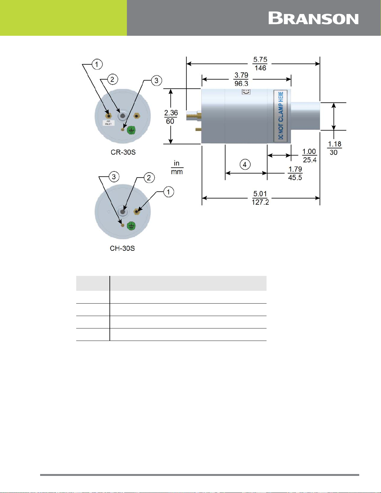
Figure 6.4 30 kHz Converter Dimensions
Table 6.4 30 kHz Converter Dimensions
Item Description
1 Air inlet
2 SHV connector
3 Ground stud
4 Grip area
CR-30S and CH-30S are dimensionally identical, and differ only in their respective cooling
feature.
CR-30S has flow through cooling, and CH-30S has closed loop cooling (air circulates in the
converter and returns to its source).
100-412-199 REV. 07 83

Figure 6.5 30 kHz Booster Dimensions
Table 6.5 30 kHz Booster Dimensions
Item Description
1 3/8 - 24 x 1 - 1/4 stud
2 Grip Ring Diameter
3 Variable
4 Varies with tuning and gain
* These dimensions do not vary.
84 100-412-199 REV. 07

Figure 6.6 30 kHz Converter/Booster/Horn, Typical Dimensions
Table 6.6 30 kHz Converter/Booster/Horn, Typical Dimensions
Item Description
1 Converter
2 Booster
3 One-half wavelength horn
4 Recommended clamping area
5
* Overall horn length can vary beyond these typical dimensions depending on the application.
Booster front end diameter will vary with
amplitude
100-412-199 REV. 07 85

Figure 6.7 40 kHz, 4TR Converter Dimensions
Table 6.7 40 kHz, 4TR Converter Dimensions
Item Description
1 Ground stud
2 SHV connector
3 Grip area
86 100-412-199 REV. 07

Figure 6.8 40 kHz Booster Dimensions
Table 6.8 40 kHz Booster Dimensions
Item Description
M8 x 1 - 1/4 stud (Ti boosters)
1
M8 x 1 - 1/2 stud (Al boosters)
2 Grip ring diameter
3 Variable
4 Varies with tuning and gain
100-412-199 REV. 07 87

Figure 6.9 40 kHz Converter/Booster/Horn, Typical Dimensions
Table 6.9 40 kHz Converter/Booster/Horn, Typical Dimensions
Item Description
1 Converter
2 Booster
3 One-half wavelength horn
4 Recommended clamping area
5
* Overall horn length can vary beyond these typical dimensions depending on the application.
** Dimension varies with tuning and gain.
Booster front end diameter will vary with
amplitude
6.1.1 Component Functional Description
Ultrasonic Stack
Converter
The converter is mounted in the customer's automation as part of the ultrasonic stack.
The ultrasonic electrical energy from the power supply is applied to the converter
(sometimes called the transducer). This transforms the high frequency electrical
oscillations into mechanical vibrations at the same frequency as the electrical oscillations.
The heart of the converter are piezoelectric ceramic elements. When subjected to an
alternating voltage, these elements alternately expand and contract, resulting in better
than 90% conversion of electrical to mechanical energy.
88 100-412-199 REV. 07
 Loading...