


2000X aod
Actuator
Instruction Manual
EDP 100-214-282
Rev. 07
Software Version 10.xx and above
BRANSON Ultrasonics Corporation
41 Eagle Road
Danbury, Connecticut 06813-1961 U.S.A.
(203) 796-0400

ii2000X aod Actuator

Manual Change Information
NOTE
i
i
At Branson, we strive to maintain our position as the leader in ultrasonics plastics joining, cleaning
and related technologies by continually improving our circuits and components in our equipment.
These improvements are incorporated as soon as they are developed and thoroughly tested.
Information concerning any improvements will be added to the appropriate technical documentation
at its next revision and printing. Therefore, when requesting service assistance for specific units, note
the Revision information found on the cover of this document, and refer to the printing date which
appears at the bottom of this page.
Copyright
Loctite is a registered trademark of Henkel Corporation U.S.A.
Other trademarks and service marks mentioned herein are held by their respective
owners.
© BRANSON Ultrasonics Corporation Printed in U.S.A. September 2017

2000X aod
Actuator
Instruction Manual
Foreword
Congratulations on your choice of a Branson Ultrasonics Corporation system!
The Branson 2000X-Series system is process equipment for the joining of plastic parts using
ultrasonic energy. It is the newest generation of product using this sophisticated technology for
a variety of customer applications. This Instruction Manual is part of the documentation set for
this system, and should be kept with the equipment.
Thank you for choosing Branson!
Introduction
This manual is arranged into several structured chapters which will help you find the information
you may need to know to safely handle, install, set up, program, operate, and/or maintain this
product. Please refer to the Table of Contents and/or the Index of this manual to find the information you may be looking for. In the event you require additional assistance or information,
please contact our Product Support department (see How to Contact Branson
information on how to contact them) or your local Branson representative.
iv 100-214-282 Rev. 07
on page 1-10 for

2000X aod Actuator
Instruction Manual
Table of Contents
1 Safety and Support
1.1 Safety Requirements and Warnings - - - - - - - - - - - - - 1-2
1.1.1 Symbols Found in this Manual - - - - - - - - - - - - - - - 1-2
1.1.2 Symbols Found on the Product - - - - - - - - - - - - - - - 1-2
1.2 General Precautions - - - - - - - - - - - - - - - - - - - - - 1-3
1.2.1 Intended Use of the System - - - - - - - - - - - - - - - - 1-5
1.2.2 Safety Measures and Guards- - - - - - - - - - - - - - - - 1-5
1.2.3 Emissions - - - - - - - - - - - - - - - - - - - - - - - - - 1-6
1.2.4 Setting up the Workplace- - - - - - - - - - - - - - - - - - 1-6
1.2.5 Regulatory Compliance - - - - - - - - - - - - - - - - - - 1-6
1.3 Warranty Statement, Disclaimer - - - - - - - - - - - - - - - 1-7
1.4 How to Contact Branson - - - - - - - - - - - - - - - - - - 1-10
1.4.1 Before Calling Branson for Assistance - - - - - - - - - - - 1-10
1.5 Returning Equipment for Repair - - - - - - - - - - - - - - 1-11
1.5.1 Get an RGA Number - - - - - - - - - - - - - - - - - - - - 1-12
1.5.2 Record information about the Problem - - - - - - - - - - -1-12
1.5.3 Departments to Contact - - - - - - - - - - - - - - - - - - 1-13
1.5.4 Pack and Ship the Equipment - - - - - - - - - - - - - - -1-14
1.6 Obtaining Replacement Parts- - - - - - - - - - - - - - - - 1-14
2 Introduction to the 2000X aod Actuator
2.1 Models Covered- - - - - - - - - - - - - - - - - - - - - - - - 2-1
2.1.1 Power Supply Manual Set - - - - - - - - - - - - - - - - - 2-2
2.2 Overview of this Model - - - - - - - - - - - - - - - - - - - - 2-3
2.3 Features of the System - - - - - - - - - - - - - - - - - - - - 2-4
2.4 Controls and Indicators- - - - - - - - - - - - - - - - - - - - 2-6
2.5 Welding Systems - - - - - - - - - - - - - - - - - - - - - - - 2-7
2.6 Glossary of Terms - - - - - - - - - - - - - - - - - - - - - - 2-9
100-214-282 Rev. 07 v

3 Delivery and Handling
3.1 Shipping and Handling - - - - - - - - - - - - - - - - - - - - 3-1
3.1.1 Environmental Specifications - - - - - - - - - - - - - - - - 3-1
3.2 Receiving - - - - - - - - - - - - - - - - - - - - - - - - - - - 3-2
3.3 Unpacking - - - - - - - - - - - - - - - - - - - - - - - - - - 3-3
3.3.1 Actuator Assemblies - - - - - - - - - - - - - - - - - - - - 3-3
3.4 Returning Equipment - - - - - - - - - - - - - - - - - - - - - 3-3
4 Installation and Setup
4.1 About Installation - - - - - - - - - - - - - - - - - - - - - - - 4-2
4.2 Handling and Unpacking - - - - - - - - - - - - - - - - - - - 4-2
4.2.1 Unpack the Stand or Actuator - - - - - - - - - - - - - - - 4-3
4.2.2 Stand (actuator on a base) - - - - - - - - - - - - - - - - - 4-4
4.2.3 Stand (Actuator on a Hub) - - - - - - - - - - - - - - - - - 4-5
4.2.4 Actuator (Alone) - - - - - - - - - - - - - - - - - - - - - - 4-6
4.3 Take Inventory of Small Parts - - - - - - - - - - - - - - - - 4-7
4.3.1 Cables - - - - - - - - - - - - - - - - - - - - - - - - - - - 4-8
4.4 Installation Requirements - - - - - - - - - - - - - - - - - - 4-9
4.4.1 Location - - - - - - - - - - - - - - - - - - - - - - - - - - 4-9
4.4.2 Environmental Specifications - - - - - - - - - - - - - - - - 4-9
4.4.3 Electrical Input Power Ratings - - - - - - - - - - - - - - - 4-10
4.4.4 Air Cylinder Consumption - - - - - - - - - - - - - - - - -4-11
4.4.5 Factory Air - - - - - - - - - - - - - - - - - - - - - - - - - 4-15
4.5 Installation Steps - - - - - - - - - - - - - - - - - - - - - - 4-16
4.5.1 Mounting the Stand (Actuator on Base) - - - - - - - - - -4-16
4.5.2 Mounting the Stand (Actuator on Hub-mounted column)- - - 4-17
4.5.3 Actuator (Alone) - - - - - - - - - - - - - - - - - - - - - - 4-19
4.5.4 Mount the Power Supply - - - - - - - - - - - - - - - - - -4-20
4.5.5 Input Power (Main)- - - - - - - - - - - - - - - - - - - - - 4-21
4.5.6 Output Power (RF Cable) - - - - - - - - - - - - - - - - - 4-21
4.5.7 Interconnect between Power Supply and Actuator - - - - - 4-21
4.5.8 Start Switch Connection (Automation) - - - - - - - - - - - 4-23
4.5.9 Serial (RS-232) Port Connector- - - - - - - - - - - - - - - 4-24
4.5.10 Parallel Printer Connector - - - - - - - - - - - - - - - - - 4-24
4.5.11 User I/O Interface - - - - - - - - - - - - - - - - - - - - -4-25
4.5.12 Input Power Plug- - - - - - - - - - - - - - - - - - - - - - 4-28
4.5.13 User I/O DIP Switch (SW1) - - - - - - - - - - - - - - - - - 4-29
vi 100-214-282 Rev. 07

2000X aod Actuator
Instruction Manual
4.5.14 Module Options DIP Switch - - - - - - - - - - - - - - - - 4-29
4.6 Guards and Safety Equipment - - - - - - - - - - - - - - - 4-30
4.6.1 Emergency Stop Control - - - - - - - - - - - - - - - - - -4-30
4.7 Rack Mount Installation- - - - - - - - - - - - - - - - - - - 4-31
4.8 Assemble the Acoustic Stack - - - - - - - - - - - - - - - 4-32
4.8.1 For a 20kHz System - - - - - - - - - - - - - - - - - - - - 4-32
4.8.2 For a 30kHz System - - - - - - - - - - - - - - - - - - - - 4-33
4.8.3 For a 40kHz System - - - - - - - - - - - - - - - - - - - - 4-33
4.8.4 Assembling the 20kHz Acoustic Stack - - - - - - - - - - - 4-34
4.8.5 Connecting Tip to Horn- - - - - - - - - - - - - - - - - - -4-35
4.8.6 Installing the Stack in the Actuator - - - - - - - - - - - - -4-36
4.9 Mounting the Fixture on the Branson Base- - - - - - - - - 4-38
4.10 Testing the Installation - - - - - - - - - - - - - - - - - - - 4-39
4.11 Still Need Help? - - - - - - - - - - - - - - - - - - - - - - - 4-40
5 Technical Specifications
5.1 Technical Specifications - - - - - - - - - - - - - - - - - - - 5-1
5.1.1 Requirement Specifications - - - - - - - - - - - - - - - - 5-1
5.1.2 Performance Specifications - - - - - - - - - - - - - - - - 5-2
5.2 Physical Description - - - - - - - - - - - - - - - - - - - - - 5-3
5.2.1 Standard Items- - - - - - - - - - - - - - - - - - - - - - - 5-3
6Operation
6.1 Actuator Controls- - - - - - - - - - - - - - - - - - - - - - - 6-1
6.2 Initial Actuator Settings- - - - - - - - - - - - - - - - - - - - 6-2
6.2.1 Regulated Air Pressure and Air Pressure Gauge - - - - - - 6-2
6.2.2 Factory Air Source - - - - - - - - - - - - - - - - - - - - - 6-3
6.2.3 Downspeed Control - - - - - - - - - - - - - - - - - - - - 6-3
6.2.4 Actuator Alignment and Height (Horn travel) - - - - - - - - 6-4
6.2.5 Mechanical Stop - - - - - - - - - - - - - - - - - - - - - - 6-4
6.2.6 Emergency Stop - - - - - - - - - - - - - - - - - - - - - - 6-5
6.3 Operating the Actuator - - - - - - - - - - - - - - - - - - - - 6-5
7 Maintenance
7.1 Calibration - - - - - - - - - - - - - - - - - - - - - - - - - - 7-1
7.2 Periodic and Preventive Maintenance - - - - - - - - - - - - 7-1
7.2.1 Periodically Clean the Equipment - - - - - - - - - - - - - - 7-1
7.2.2 Recondition the Stack (converter, booster, and horn) - - - - 7-2
100-214-282 Rev. 07 vii

7.2.3 Routine Component Replacement - - - - - - - - - - - - - 7-4
7.3 Parts Lists - - - - - - - - - - - - - - - - - - - - - - - - - - 7-5
Index
viii 100-214-282 Rev. 07

2000X aod Actuator
Instruction Manual
List of Figures
fig. 1.1 Connector label on the aod Actuator - - - - - - - - - - - - - - - - - - - - - - - - 1-2
fig. 1.2 Caution label on the aod Actuator for the factory air supply - - - - - - - - - - - - - 1-3
fig. 1.3 Safety Labels on front of the aod Actuator - - - - - - - - - - - - - - - - - - - - - 1-3
fig. 2.1 Right Side View of the 2000Xaod Actuator - - - - - - - - - - - - - - - - - - - - 2-2
fig. 4.1 Linear Encoder is Sensitive; Do Not Handle it! - - - - - - - - - - - - - - - - - - - 4-3
fig. 4.2 Unpacking the Stand (Actuator on a Base); Right-side View of Stand - - - - - - - - 4-4
fig. 4.3 Unpacking the Stand (Actuator on a Hub); Hub Shown Separately - - - - - - - - - 4-5
fig. 4.4 Ultrasonic Converter (J-Type for Stand-Alone Use) and Booster - - - - - - - - - - 4-7
fig. 4.5 Power Supply Dimensional Drawing - - - - - - - - - - - - - - - - - - - - - - - - 4-12
fig. 4.6 aod Actuator Dimensional Drawing - - - - - - - - - - - - - - - - - - - - - - - - - 4-13
fig. 4.7 Block Wiring Diagram - - - - - - - - - - - - - - - - - - - - - - - - - - - - - - - 4-14
fig. 4.8 Base Mounting Centers - - - - - - - - - - - - - - - - - - - - - - - - - - - - - -4-17
fig. 4.9 Mounting Bolt Pattern for the Hub (for Stand on Hub) - - - - - - - - - - - - - - - - 4-18
fig. 4.10 Rear view of Actuator, showing Mounting Surface, Bolt and Guide Pin locations- - 4-19
fig. 4.11 Connections on Rear of Power Supply - - - - - - - - - - - - - - - - - - - - - - - 4-20
fig. 4.12 Electrical Connections from Power Supply to a 2000-series Actuator - - - - - - - - 4-22
fig. 4.13 Start Switch Connection Codes - - - - - - - - - - - - - - - - - - - - - - - - - - 4-23
fig. 4.14 User I/O Cable Identification and Wire Color Diagram- - - - - - - - - - - - - - - -4-25
fig. 4.15 Line Cord Color Code - - - - - - - - - - - - - - - - - - - - - - - - - - - - - - - 4-28
fig. 4.16 Actuator Emergency Stop Button - - - - - - - - - - - - - - - - - - - - - - - - - - 4-30
fig. 4.17 Detail of Rack Mount Handle Kit Assembly - - - - - - - - - - - - - - - - - - - - -4-31
fig. 4.18 Assembling the 20kHz Acoustic Stack - - - - - - - - - - - - - - - - - - - - - - - 4-34
fig. 4.19 Connecting Tip to Horn - - - - - - - - - - - - - - - - - - - - - - - - - - - - - - 4-35
fig. 4.20 Installing a 20kHz Stack in a Branson Actuator - - - - - - - - - - - - - - - - - - - 4-36
fig. 4.21 Installing a 40kHz Stack in a Branson Actuator - - - - - - - - - - - - - - - - - - - 4-37
fig. 4.22 Mounting Circles on Base - - - - - - - - - - - - - - - - - - - - - - - - - - - - - 4-38
fig. 4.23 Normal Front Panel Display After Power-Up - - - - - - - - - - - - - - - - - - - - 4-39
fig. 5.1 2000X Actuator Pneumatic System- - - - - - - - - - - - - - - - - - - - - - - - - 5-5
100-214-282 Rev. 07 ix

x 100-214-282 Rev. 07

2000X aod Actuator
Instruction Manual
List of Tables
tab. 1 .1 Warranty Period - - - - - - - - - - - - - - - - - - - - - - - - - - - - 1-8
tab. 1.2 Branson Contacts - - - - - - - - - - - - - - - - - - - - - - - - - - -1-13
tab. 3.1 Environmental Specifications - - - - - - - - - - - - - - - - - - - - - 3-1
tab. 4.1 Small Parts included (=x) : Power Supply and/or Actuator Assemblies - 4-7
tab. 4.2 List of Cables - - - - - - - - - - - - - - - - - - - - - - - - - - - - - 4-8
tab. 4.3 Environmental Specifications - - - - - - - - - - - - - - - - - - - - - 4-9
tab. 4.4 Input Power requirements - - - - - - - - - - - - - - - - - - - - - - -4-10
tab. 4.5 Printer Compatibility - - - - - - - - - - - - - - - - - - - - - - - - - - 4-24
tab. 4.6 User I/O Cable Pin Assignments, Alphabetical Order - - - - - - - - - -4-26
tab. 4.7 User I/O Input and Output Function Selection - - - - - - - - - - - - -4-28
tab. 4.8 User I/O DIP Switch Functions - - - - - - - - - - - - - - - - - - - - -4-29
tab. 4.9 Tools - - - - - - - - - - - - - - - - - - - - - - - - - - - - - - - - - 4-32
tab. 4.10 Stud Torque Values - - - - - - - - - - - - - - - - - - - - - - - - - -4-34
tab. 4.11 Tip to Horn Torque Specifications - - - - - - - - - - - - - - - - - - - 4-35
tab. 5.1 Environmental Specifications - - - - - - - - - - - - - - - - - - - - - 5-1
tab. 5.2 Maximum Welding Force (at 100 psig and 4.0” stroke) - - - - - - - - - 5-2
tab. 5.3 Dynamic Trigger Force- - - - - - - - - - - - - - - - - - - - - - - - - 5-2
tab. 5.4 Dynamic Follow-Through - - - - - - - - - - - - - - - - - - - - - - - 5-2
tab. 5.5 Maximum Traverse Speed - - - - - - - - - - - - - - - - - - - - - - - 5-2
tab. 5.6 Description of Controls on Base - - - - - - - - - - - - - - - - - - - - 5-3
tab. 7.1 Component Replacements Based on Cycles Run - - - - - - - - - - - 7-4
tab. 7.2 Accessories List for aod Actuator - - - - - - - - - - - - - - - - - - - 7-5
tab. 7.3 Spare Parts List for the aod Actuator - - - - - - - - - - - - - - - - - - 7-7
tab. 7.4 Suggested Spares - - - - - - - - - - - - - - - - - - - - - - - - - - - 7-9
100-214-282 Rev. 07 xi

xii 100-214-282 Rev. 07

2000X aod Actuator Chapter 1: Safety and Support
Instruction Manual
Chapter 1: Safety and Support
1.1 Safety Requirements and Warnings - - - - - - - - - - - - - 1-2
1.1.1 Symbols Found in this Manual - - - - - - - - - - - - - - - 1-2
1.1.2 Symbols Found on the Product - - - - - - - - - - - - - - - 1-2
1.2 General Precautions - - - - - - - - - - - - - - - - - - - - - 1-3
1.2.1 Intended Use of the System - - - - - - - - - - - - - - - - 1-5
1.2.2 Safety Measures and Guards - - - - - - - - - - - - - - - - 1-5
1.2.3 Emissions - - - - - - - - - - - - - - - - - - - - - - - - - 1-6
1.2.4 Setting up the Workplace - - - - - - - - - - - - - - - - - - 1-6
1.2.5 Regulatory Compliance- - - - - - - - - - - - - - - - - - - 1-6
1.3 Warranty Statement, Disclaimer - - - - - - - - - - - - - - - 1-7
1.4 How to Contact Branson - - - - - - - - - - - - - - - - - - 1-10
1.4.1 Before Calling Branson for Assistance - - - - - - - - - - 1-10
1.5 Returning Equipment for Repair - - - - - - - - - - - - - - 1-11
1.5.1 Get an RGA Number - - - - - - - - - - - - - - - - - - - 1-12
1.5.2 Record information about the Problem - - - - - - - - - - 1-12
1.5.3 Departments to Contact - - - - - - - - - - - - - - - - - 1-13
1.5.4 Pack and Ship the Equipment - - - - - - - - - - - - - - 1-14
1.6 Obtaining Replacement Parts- - - - - - - - - - - - - - - - 1-14
This chapter contains an explanation of the different Safety Notice symbols and icons found both
in this manual and on the product itself and provides additional safety information for ultrasonic
welding. This chapter also describes how to contact Branson for assistance.
100-214-282 Rev. 07 1-1

Chapter 1: Safety and Support
NOTE
i
i
CAUTION
!
WARNING
!
Safety Requirements and Warnings
1.1 Safety Requirements and Warnings
1.1.1 Symbols Found in this Manual
Three symbols used throughout this manual warrant special attention:
A Note contains important information. It does not alert the user to potential injury,
but only to a situation that might eventually require additional work or modification
if you ignore it initially.
A Caution indicates a potentially hazardous situation that, if not avoided, can
result in minor or moderate injury. It might also alert the user to unsafe practices
or conditions that can damage equipment if not corrected.
A Warning indicates a hazardous situation or practice that, if not avoided, can
result in serious injury or death.
1.1.2 Symbols Found on the Product
Familiar graphic warning symbols are used to alert the user to items of concern or hazard. The
following warning symbols appear on the 2000aod Actuator
Figure 1.1 Connector label on the aod Actuator
1-2 100-214-282 Rev. 07

2000X aod Actuator Chapter 1: Safety and Support
Instruction Manual General Precautions
Figure 1.2 Caution label on the aod Actuator for the factory air supply
Figure 1.3 Safety Labels on front of the aod Actuator
1.2 General Precautions
Take the following precautions before servicing the power supply:
• Be sure the power switch is in the Off position before making any electrical connections.
• To prevent the possibility of an electrical shock, always plug the power supply into a
grounded power source.
• Power supplies produce high voltage. Before working on the power supply module, do the
following:
• Turn off the power supply;
• Unplug main power; and
• Allow at least 2 minutes for capacitors to discharge.
• High voltage is present in the power supply. Do not operate with the cover removed.
• High line voltages exist in the ultrasonic power supply module. Common points are tied to
100-214-282 Rev. 07 1-3

Chapter 1: Safety and Support
NOTE
i
i
General Precautions
circuit reference, not chassis ground. Therefore, use only non-grounded, battery-powered
multimeters when testing these modules. Using other types of test equipment can present a
shock hazard.
• Be sure power is disconnected from the power supply before setting a DIP switch.
• Keep hands from under the horn. Down force (pressure) and ultrasonic vibrations can cause
injury.
• Do not cycle the welding system if either the RF cable or converter is disconnected.
• When using larger horns, avoid situations where fingers could be pinched between the horn
and the fixture.
• Be aware that the actuator is "armed" if air pressure is indicated by the pressure indicator on
the actuator front panel and/or the air pressure gauge in the remote box.
• In normal operation, bearing seals will retain an adequate amount of grease for safe bearing
operation. Bearing can leak but contains enough grease for the life of the bearing. Removing
and running without grease will void the warranty. For more information contact product support.
Sound level and frequency of the noise emitted during the ultrasonic assembly
process may depend upon a. type of application, b. size, shape and composition
of the material being assembled, c. shape and material of the holding fixture, d.
welder setup parameters and e. tool design. Some parts vibrate at an audible frequency during the process. Some or all of these factors may result in an uncomfortable noise being emitted during the process. In such cases operators may
need to be provided with personal protective equipment. See 29 CFR (Code of
Federal Regulations) 1910.95 Occupational Noise Exposure.
Manufacturers of Protective Materials and Equipment
Safeware, Inc
9475 Lottsford Rd.
Suite 150
Largo, MD 20774-5351
www.safewareinc.com
Hearing Protectors
David Clark
360 Franklin St.
Box 15054
Worcester, MA 01615-0054
www.davidclark.com
1-4 100-214-282 Rev. 07

2000X aod Actuator Chapter 1: Safety and Support
Instruction Manual General Precautions
Softcomm Products
2310 - T South Airport Blvd.
Chandler, AZ 85224
Sound Absorbing Material
American Acoustical Products
6 October Hill Road
Holliston, MA 01746
Singer Safety Co.
2300 W. Logan Blvd.
Chicago IL 60647-2023
Polymer Technologies, Inc.
420 - T Corporate Blvd.
Newark, DE 19702
Static Protection Equipment
Polygenex
PO Box 4468
Cary, NC 27519
Elvex Corp
13 Trowbridge Drive
Bethel, CT 06801
Tamer Industries
185 Riverside Av.
Somerset MA 02725
Foamex
1501 E. Second St.
Eddystone PA 19022
Soundcoat Company
1 Burt Drive
Deer Park, NY 11729
Electrostatics, Inc.
352D Godshall Dr.
Harleysville, PA 19438-2017
Terra Universal
700 - N Harbor Blvd.
Anaheim, CA 92805
www.terrauni.com
1.2.1 Intended Use of the System
The 2000X-series Power Supply and aod Actuator are components of an ultrasonic welding system. These are designed for a wide variety of welding or processing applications.
1.2.2 Safety Measures and Guards
The2000X aod Actuator, along with its 2000X distance Power Supply, contains software-controlled electronic safety devices intended to prevent the machine from operating in a fashion
harmful to the user. Start Switch and Emergency Stop controls are designed to prevent undesirable startup.
100-214-282 Rev. 07 1-5

Chapter 1: Safety and Support
CAUTION
!
General Precautions
1.2.3 Emissions
When being processed, certain plastic materials can emit toxic fumes, gases or other emissions
that can be hazardous to the operator’s health. Where such materials are processed, proper ventilation of the workstation is required. Check your materials suppliers for recommended protection when processing their materials.
Processing of many materials, such as PVC, can be hazardous to an operator’s
health and could cause corrosion/damage to the equipment. Use proper ventilation and take protective measures.
1.2.4 Setting up the Workplace
Measures for setting up a workplace for safe operation of the ultrasonic welder are outlined in
Chapter 4: Installation and Setup and in the 2000-series Installation Guide.
1.2.5 Regulatory Compliance
The Branson 2000aod actuator and converter receive their power and control from a 2000Xseries power supply, and together make up a system. The 2000d power supply is designed for
compliance with the following domestic (U.S.A.) and other regulatory guidelines.
• ANSI Z535.1 Safety Color Code
• ANSI Z535.3 Criteria for Safety Symbols
• ANSI Z535.4 Product Safety Signs and Labels
• BS EN ISO 12100-1, -2 Safety of Machinery - Basic concepts, general guidelines for design
• EN 55011 Limits and methods of measurement of radio disturbance of industrial, scientific
and medical radio-frequency equipment
• EN 60204-1 Safety of Machinery - Electrical Equipment of machines
• EN 60529 Degrees of protection provided by enclosure
• EN 60664-1 Insulation coordination for equipment within low-voltage systems
• EN 61000-3-3 Electromagnetic Compatibility - Limitations of voltage fluctuations and flicker
in low voltage supply systems (for European products that draw less than 1000 watts from
the line at full rated power)
• EN 61000-6-2 Electromagnetic Compatibility - Generic standards - Immunity for industrial
environments
• EN 61310-2 Safety of Machinery - Indication, marking, actuation
• NFPA 70 National Electrical Code Article 670 Industrial Machinery
• NFPA 79 Electrical Standard for Industrial Machinery
1-6 100-214-282 Rev. 07

2000X aod Actuator Chapter 1: Safety and Support
Instruction Manual Warranty Statement, Disclaimer
• 29 CFR 1910.212 OSHA General Requirements for all machines
• 47 CFR Part 18 Federal Communication Commission
All products with CE Mark require: Same as above plus
• EN 61000-3-2 Electromagnetic Compatibility - Limits for harmonic emissions (for European
products that draw less than 1000 watts from the line at full rated power)
1.3 Warranty Statement, Disclaimer
The following excerpts from the “Terms and Conditions of Sale” (found on the back of your
Invoice) are essential guidelines for the product Warranty issued with your Branson ultrasonic
welding components. The items listed in this section specifically address issues involving the
delivery, shipment, and warranty period provided. If you have any questions, please refer to the
back of the Invoice included with your system, which lists all of the Terms and Conditions of
Sale, or contact your Branson representative.
TERMS AND CONDITIONS OF SALE
Branson Ultrasonics Corporation is herein referred to as the “Seller” and the customer or person
or entity purchasing products (“Products”) from Seller is referred to as the “Buyer.” Buyer’s
acceptance of the Products will manifest Buyer’s assent to these Terms and Conditions.
100-214-282 Rev. 07 1-7

Chapter 1: Safety and Support
Warranty Statement, Disclaimer
ULTRASONIC JOINING EQUIPMENT NORTH AMERICAN WARRANTY POLICY
Each product manufactured by Branson is guaranteed to be free from defects in material and
workmanship for a period of time specified in Table 1 .1
invoice.
Table 1 .1 Warranty Period
Power Supplies 36 months
Actuators 36 months
Actuator, Special 12 months
Integrated Welders 36 months
Accessories 36 months
Warranty Period from the date of
Converters 36 months (limited to one-time replacement)
Non-Branson equipment
(i.e. printers)
Horns 12 months (limited to one-time replacement)
Boosters 36 months
Rental Equipment Same as purchased equipment
Specials and products with EDP prefix
159-xxx-xxx
Specials and products with EDP prefix
125-xxx-xxx
warranted by the manufacturer
12 months
12 months
The warranty does not apply to:
• any product which has been subject to misuse, misapplication, neglect (including
without limitation inadequate maintenance), accident or improper installation, modification or adjustment.
• applications requiring metal-to-metal contact when the ultrasonic exposure time
exceeds 1.5 seconds.
• any product exposed to adverse environments, improper repair or repairs using nonBranson methods or material.
• non-Branson equipment (i.e., horns, boosters, converters) or improperly tuned
horns.
• Set up/installation of equipment and software updates.
1-8 100-214-282 Rev. 07

2000X aod Actuator Chapter 1: Safety and Support
Instruction Manual Warranty Statement, Disclaimer
Warranty Service covers the following:
Repair service at Branson´s main repair facility or a regional office
• Includes parts and labor performed at Branson authorized repair facilities. The customer
must return the equipment properly packed with all shipping charges prepaid.
Repair service at the customer site
• Includes parts and labor at the customer site performed by a Branson technician. The customer is responsible for all travel-related charges.
Module trade-in:
• Includes serialized components for work performed by the customer. The customer
orders the replacement components from the Parts Store and issues a P.O. When
the failed components are returned to Branson the warranty status is verified and a
credit is issued. The customer is responsible for all shipping charges.
Additional Warranty Notes
• Components replaced during in-warranty repair carries the remainder of the original
warranty.
• Serialized assemblies replaced during the repair of out-of-warranty equipment are
warranted for a period of 12 months.
• Travel charges for Branson service personnel will be waived on service calls performed within 30 days of invoice date.
• Non-serialized parts replaced during the repair of out-of-warranty equipment are
warranted for 3 months.
• Trade in allowance: Branson out-of-warranty serialized components are entitled to a
25% trade in allowance regardless of age or condition, however, converters must be
less than 5 years old to qualify for the trade in.
If you have any questions concerning the warranty coverage (including coverage outside of
North America), please contact your Branson representative or Branson Customer Support.
100-214-282 Rev. 07 1-9

Chapter 1: Safety and Support
How to Contact Branson
1.4 How to Contact Branson
Branson is here to help you. We appreciate your business and are interested in helping you successfully use our products. To contact Branson for help, use the following telephone numbers,
or contact the field office nearest you.
• Danbury Main Number (all Departments): (203) 796-0400 (Eastern Time Zone)
• Parts Store (direct number): (877) 330-0406 (Central Time Zone)
• Repair department: (877)-330-0405 (Central Time Zone)
• For emergency after-hours service (5pm-8am Est): (203) 796-0500 (US phone numbers
only).
Tell the operator which product you have and which person or department you need (see Section
1.5.3
Departments to Contact). If you are calling after hours, please leave a voice message with
your name and return telephone number.
1.4.1 Before Calling Branson for Assistance
This manual provides information for troubleshooting and resolving problems that could occur
with the equipment (see Chapter 7). If you still require assistance, Branson Product Support is
here to help you. To help identify the problem, use the following questionnaire which lists the
common questions you will be asked when you contact the Product Support department.
Before calling, determine the following information:
1. Your company name and location.
2. Your return telephone number.
3. Have your manual with you. If troubleshooting a problem, refer to Chapter 7.
4. Know your equipment model and serial numbers (found on a gray data label on the units).
Information about the Horn (part number, gain, etc.) or other tooling may be etched into the
tooling. Software- or firmware-based systems may provide a BOS or software version number, which may be required.
5. What tooling (horn) and booster are being used?
6. What are the setup parameters and mode?
7. Is your equipment in an automated system? If so, what is supplying the “start” signal?
8. Describe the problem; provide as much detail as possible. For example, is the problem intermittent? How often does it occur? How long before it occurs if you are just powering up? If
an error is occurring, which error (give error number or name)?
9. List the steps you have already taken.
10. What is your application, including the materials being processed?
11. Have a list of service or spare parts you have on hand (tips, horns, etc.)
12. Notes: __________________________________________________________________
_______________________________________________________________________
_______________________________________________________________________
1-10 100-214-282 Rev. 07

2000X aod Actuator Chapter 1: Safety and Support
NOTE
i
i
Instruction Manual Returning Equipment for Repair
1.5 Returning Equipment for Repair
Before sending equipment for repair, provide as much information with the equipment to help
determine the problem with the system. Fill in any details below or on a separate sheet.
Describe the problem; provide as much detail as possible. For example, is this a new problem?
Is the problem intermittent? How often does it occur? How long before it occurs if you are just
powering up?
________________________________________________________________________
________________________________________________________________________
________________________________________________________________________
To return equipment to Branson, you must first obtain an RGA number from a
Branson representative, or the shipment may be delayed or refused.
If you are returning equipment to Branson for repair, you must first call the Repair department
to obtain a Returned Goods Authorization
ment will fax a Returned Goods Authorization form to fill out and return with your equipment.)
Branson Repair Department, C/O Zuniga Logistics, LTD
2013 Sara Road, Killam Industrial Park
Laredo, Texas 78045 U.S.A. direct
telephone number: (877) 330-0405
fax number: (877) 330-0404
• Provide as much information as possible that will help identify the need for repair.
• Carefully pack the equipment in original packing cartons.
• Clearly label all shipping cartons with the RGA number on the outside of cartons as well as
on your packing slip, along with the reason for return.
• Return general repairs by any convenient method. Send priority repairs by air freight.
• You must prepay the transportation charges FOB Laredo, Texas, U.S.A.
(RGA) number. (If you request it, the repair depart-
100-214-282 Rev. 07 1-11

Chapter 1: Safety and Support
Returning Equipment for Repair
1.5.1 Get an RGA Number
RGA# _____________
If you are returning equipment to Branson, please call the Repair Department to obtain a
Returned Goods Authorization (RGA) number. (At your request, the Repair Department will fax
an RGA form to fill out and return with the equipment.)
1.5.2 Record information about the Problem
Before sending equipment for repair, record the following information and send a copy of it with
the equipment. This will greatly increase Branson’s ability to address the problem.
1. Describe the problem; provide as much detail as possible.
For example, is the problem intermittent? How often does it occur? How long before it
occurs after powering up?
________________________________________________________________________
________________________________________________________________________
________________________________________________________________________
________________________________________________________________________
2. Is your equipment in an automated system? NO / YES
3. If the problem is with an external signal, which signal? ______________________
If known, include plug/pin # (e.g., P29, pin #3) for that signal: _________________
4. What are the Weld Parameters?
________________________________________________________________________
________________________________________________________________________
5. What is your application? (Type of weld, plastic material, etc.)
________________________________________________________________________
6. Name and phone number of the person most familiar with the problem:
________________________________________________________________________
________________________________________________________________________
7. Contact the Branson office prior to shipping the equipment.
8. For equipment not covered by warranty, to avoid delay, include a Purchase Order.
Send a copy of this page with the equipment being returned for repair.
1-12 100-214-282 Rev. 07

2000X aod Actuator Chapter 1: Safety and Support
Instruction Manual Returning Equipment for Repair
1.5.3 Departments to Contact
Call your local Branson Representative, or contact Branson by calling, and asking for the appropriate
department as indicated in Table 1.2:
Table 1.2 Branson Contacts
Branson Contacts below.
What you need help with or information about . . . Whom to Call
Your local Branson Rep
Information about new welding systems or components
Application and Setup questions on the
welding system
Application assistance on the Horns and
Tooling
Technical questions about the welding system Welding Product Support
Technical questions about Horns and Tooling ATG Lab
Ordering new parts Parts Store 877-330-0406
RGA’s, Request for Repair, Status of a Repair
System Automation/Hookup Information Product Support
or Branson Customer
Service
Welding Applications Lab
ATG L a b
Welding Repair Department
At this Phone
Number
203-796-0400
Ext 384
203-796-0400
Ext 368
203-796-0400
Ext 495
203-796-0400
Ext 355
203-796-0400
Ext 495
877-330-0405
203-796-0400
Ext 355
My Local Branson Representative’s name is:
__________________________________________________
I can reach this representative at:
___________________________________________________________________
100-214-282 Rev. 07 1-13

Chapter 1: Safety and Support
NOTE
i
i
Obtaining Replacement Parts
1.5.4 Pack and Ship the Equipment
1. Carefully pack the system in original packing material to avoid shipping damage. Plainly show the
RGA number on the outside of cartons as well as inside the carton along with the reason for return.
Make a list of all components packed in the box. KEEP YOUR MANUAL.
2. Return general repairs by any convenient method. Send priority repairs by air freight. Prepay the
transportation charges FOB the repair site.
Items that are sent Freight Collect will be refused.
_______________________________________________________________________
_______________________________________________________________________
_______________________________________________________________________
1.6 Obtaining Replacement Parts
You can reach Branson Parts Store at the following telephone numbers:
Branson Part Store
direct telephone number: 877-330-0406
fax number: 877-330-0404
Many parts can be shipped the same day if ordered before 2:30 p.m., Eastern time.
A parts list is found in Chapter 7 of this manual, listing descriptions and EDP part numbers. If
you need replacement parts, coordinate the following with your purchasing agent:
• Purchase order number
• ‘Ship to’ information
• ‘Bill to’ information
• Shipping instructions (air freight, truck, etc.)
• Any special instructions (for example, “Hold at the airport and call”). Be sure to give a name
and phone number
• Contact name information
1-14 100-214-282 Rev. 07

2000X aod Actuator Chapter 2: Introduction to the 2000X aod Actuator
NOTE
i
i
Instruction Manual Models Covered
Chapter 2: Introduction to the 2000X aod
Actuator
2.1 Models Covered- - - - - - - - - - - - - - - - - - - - - - - - 2-1
2.1.1 Power Supply Manual Set - - - - - - - - - - - - - - - - - 2-2
2.2 Overview of this Model - - - - - - - - - - - - - - - - - - - - 2-3
2.3 Features of the System - - - - - - - - - - - - - - - - - - - - 2-4
2.4 Controls and Indicators - - - - - - - - - - - - - - - - - - - - 2-6
2.5 Welding Systems - - - - - - - - - - - - - - - - - - - - - - - 2-7
2.6 Glossary of Terms - - - - - - - - - - - - - - - - - - - - - - 2-9
The 2000X aod Actuator provides motion, force, power (from the power supply), and cooling
air to the ultrasonic stack assembly. The 2000X aod Actuator is designed to work with a Branson
2000X distance Power Supply.
2.1 Models Covered
This manual covers the Branson 2000X aod Actuator. The 2000X aod Actuator may be found in
one of several configurations:
• An Actuator on a Column Support, Column and Ergonomic Base, also called a Stand on Base
(as seen on the following page)
• An Actuator on a Column Support, Column and Mounting Hub, sometimes called a Stand on
Hub
• An Actuator alone (not installed on a Column Support, and so on.). These are often used in
custom or automated systems that provide a means of positioning the Actuator.
This manual covers these configurations. A 2000X-series actuator requires a 2000X-series
power supply to function, and that is covered in separate manuals and user documents.
Figure 2-1 shows a Branson 2000X aod Actuator mounted on a column support which, in turn
is mounted on a column, and is supported by the ergonomic base.
Pneumatics are sold separately and referred to as rp as covered by this manual.
100-214-282 Rev. 07 2-1

Chapter 2: Introduction to the 2000X aod Actuator
Base
Column Support Clamps
Actuator Support
(Optional)
Column
2000X aod Actuator
Encoder
Mechanical
Stop Adjust
Models Covered
Figure 2.1 Right Side View of the 2000Xaod Actuator
2-2 100-214-282 Rev. 07
2.1.1 Power Supply Manual Set
The following documentation is available for the Branson 2000X-series Power Supplies that are
compatible with the 2000Xaod Actuator:
• 2000X distance Power Supply Instruction Manual (EDP 100-412-167)
• 2000-Series Installation Guide (EDP 100-214-226)
• 2000X distance Quick Start User’s Guide (EDP 100-412-169)

2000X aod Actuator Chapter 2: Introduction to the 2000X aod Actuator
Instruction Manual Overview of this Model
2.2 Overview of this Model
The 2000X aod Actuator is a compact, rigid unit designed for use in manual, semi-automated,
and automated ultrasonic welding systems. The Actuator can be mounted directly on an I-beam
(or similar machine frame), or it can be mounted on a column and base with start switches and
used in a manual or benchtop system. The Actuator is designed to be operated in an upright position, but is capable of running horizontally or inverted. If you are mounting your equipment in
an inverted position, contact Branson for further recommendations. (See Section 1.5.3, Depart-
ments to Contact, on page 1-13.)
The 2000X aod Actuator requires a 2000X distance Power Supply for power and control of the
Actuator’s operation and to provide ultrasonic power to the Converter in the Actuator.
The 2000X aod Actuator is designed with remotely-mountable pneumatic controls. Operation
of the 2000X aod is controlled by inputs to the 2000X distance Power Supply. Having remote
pneumatic controls allows easier user access to the Actuator settings, often important in automated systems. The pneumatics covered in this manual refer to the remote box package sold by
Branson. Some customers may require custom controls.
The Carriage and Slide System
The 2000X aod Actuator’s carriage is driven by a double-acting air cylinder. It is mounted on a
linear ball-bearing slide. The slide system is based on eight sets of preloaded, permanently
lubricated bearings and provides consistent, precise alignment of the horn, smooth linear
motion, and long-term reliability.
The Pneumatic System
The pneumatic controls on the 2000X aod are contained in the 2000X rp Remote Pneumatics
box, which is connected to the Actuator with three (3)1/4-inch-OD poly tubing lines. The 2000X
aod Actuator’s carriage and sheet-metal enclosure contains the air cylinder, which receives air
pressure and control from the 2000X rp. There is a pressure sensor in the actuator to allow the
power supply to read the regulated air pressure.
The air pressure regulator, solenoid valves, and air pressure gauge are found in the remote box.
Filtered factory air is connected to the 2000Xaod.
The horn’s rate of descent is adjusted by the Downspeed control on the Remote Pneumatics
Box. The rate of return is fixed. For information on setting the Downspeed control, see Section
2.4: Controls and Indicators.
Dynamic Triggering and Follow-Through
Many welding applications require force to be built up on the part before ultrasonic energy is
activated. To achieve this, the Actuator contains a S-Beam load cell, located between the air cylinder and the converter, which initiates (triggers) ultrasonics after a preset force is applied to the
part. Dynamic follow-through maintains a consistent force on the part during the weld collapse.
This system helps provide uniform weld quality.
100-214-282 Rev. 07 2-3

Chapter 2: Introduction to the 2000X aod Actuator
Features of the System
The dynamic triggering and follow-through process operates as follows: upon activation of the
operating cycle, the solenoid valve delivers regulated air to the upper portion of the cylinder, and
exhausts air through the Downspeed control from the bottom of the cylinder, causing the horn
to advance and contact the workpiece. When the load cell measurement of the force on the part
indicates part contact, and the desired trigger force is reached, a signal is sent to the Power Supply, which then starts the weld cycle. At this time, the actuator locks into a cycle, timing begins,
and the palm buttons can be released. As melting of the plastic occurs, the load cell dynamic follow through maintains consistent force on the part, ensuring smooth, efficient transmission of
ultrasonic energy into the part.
2.3 Features of the System
Listed below are many features of the Branson 2000X-series ultrasonic welding system included
in a 2000X aod Actuator and 2000X distance Power Supply.
• Autotuning: Branson Power Supply tuning ensures that the system is running at
peak efficiency.
• Amplitude Stepping: A patented Branson process, controlled by the Power Supply.
At a specified time, energy, peak power, distance, or by external signal you can
change the amplitude during the weld to control the flow of plastic. This feature helps
ensure part consistency, higher strength parts and control of flash.
• Digital Horn Test Diagnostics: In Test mode of the Power Supply, you can view the
Horn Test results in digital form, using digital readouts and bar graphs on the Power
Supply to give you the best picture of the stack’s operation.
• Pretrigger: This feature allows you to set the system weld controls to turn the
ultrasonics on before contact with the part.
• Afterburst: This feature allows you to set the system weld controls to turn the
ultrasonics on after the weld and hold steps to release parts from the horn.
• Control Limits: With some power supply models, these secondary controls are
used in conjunction with the main parameters of the weld parameters. These userprogrammed limits provide for adaptive control of the weld process.
• Process Alarm Display Showing Actual and Set Values: When an alarm
condition has occurred, you can view the value for the last weld and the suspect and
reject settings you programmed into the controls.
• Post Weld Seek: This system feature provides a short burst of energy at the end of
the weld Hold and Afterburst steps to automatically retune the power supply, if
required.
• Frequency Offset: This process feature allows a user to set a frequency value, for
certain specific applications, where the force imparted on the fixture or anvil causes
a frequency shift in the Stack’s operation. You should only use this feature when
advised to do so by Branson.
• English (USCS)/Metric Units: This feature allows the welder to be set up in the
local units in use.
2-4 100-214-282 Rev. 07

2000X aod Actuator Chapter 2: Introduction to the 2000X aod Actuator
Instruction Manual Features of the System
• Startup Diagnostics: At power supply startup, the controls test the major system
components, including the Actuator and its controls.
• Weld Parameter Entry through Digital Keypad: User Setup is direct and easy, by
selecting the menu parameter by name and using the keypad to enter the precise
value. The controls also support entry by incrementing existing values.
• System Information Screen: This is a screen that will give you information about
your welding system (e.g., cylinder size, stroke length, number of cycles). Refer to
this screen when contacting Branson for service and support.
• Ramp Starting: The starting of the 2000X-series power supply and horn is done at
the optimum rate to reduce electrical and mechanical stress on the system. This also
helps make some tough-to-start applications possible.
• True Wattmeter: The controls on the power supply include a true wattmeter for
accurate measurement of power and energy.
• Load Cell/Dynamic Follow Through: c
• S-Beam Load Cell: The load cell allows the ultrasonics to be triggered at a
designated force input into the power supply.
• Encoder: Allows the power supply to monitor the distance the horn has travelled,
enabling the use of distance functions.
• Downspeed: Controls the rate of descent and force build-up on the part.
• Pressure Sensor: Allows the power supply to read the system pressure.
100-214-282 Rev. 07 2-5

Chapter 2: Introduction to the 2000X aod Actuator
NOTE
i
i
CAUTION
!
Controls and Indicators
2.4 Controls and Indicators
The Actuator Controls for the 2000X aod are found in two locations: on the Actuator or on the
Remote Pneumatics Box. The 2000X rp is a separate component of the 2000aod. System controls and Actuator power are provided by the 2000X-series Power Supply.
• Stroke Indicator Provides a quick method of determining relative carriage travel during an
operating cycle. A scale is provided to indicate relative distance.
• S-Beam Load Cell: Provides an indication of the force on a part during a weld. This indica-
tion can be used to determine when to trigger ultrasonics and also to produce a force/distance graph of the operating cycle.
The mechanical stop is not intended for welding by distance.
The front panel controls on the 2000aod Actuator are listed below.
• Pressure Indicator: Indicates that the actuator is receiving pressurized air.
• Power Light: Indicates that the Actuator is connected to the Power Supply and that the
Power Supply’s main power is on.
• Carriage Door: Provides access to the converter-booster-horn stack; secured by four cap-
tive hex screws. Use an M5 T-handle wrench (EDP 109-128-024) to tighten the cap screws.
• Mechanical Stop: Limits the stroke length to prevent the horn from contacting the fixture
when no workpiece is in place; adjustment is approximately 0.04 in. (1 mm) per rotation; a
locking ring keeps the setting from vibrating loose. Turning the knob clockwise increases the
stroke length.
Turning the mechanical stop too far can cause it to come apart.
Controls on the 2000rp Remote Pneumatics Box are listed below.
• Pressure Regulator: Adjust the amount of air pressure applied to the cylinder; range of 5-
100 psig (35-700 kPa). Pull to set; push to lock.
• Downspeed Control: Downspeed knob controls the rate of descent and force buildup on the
part to be welded.
• Pilot Light: Indicates that the actuator is connected to the power supply, that the 2000rp
remote box is electrically connected to the 2000aod actuator, and that the power supply’s
main power is on.
• Pressure Gauge: Indicates the amount of air pressure applied to the cylinder; range of 5-
100psig (35-700 kPa). Pull to set; push to lock.
2-6 100-214-282 Rev. 07

2000X aod Actuator Chapter 2: Introduction to the 2000X aod Actuator
Instruction Manual Welding Systems
2.5 Welding Systems
Ultrasonic Plastics Welding
Thermoplastic parts are welded ultrasonically by applying high-frequency vibrations to the parts
being assembled. The vibrations, through surface and intermolecular friction, produce a sharp
rise in temperature at the welding interface.
When the temperature is high enough to melt the plastic, there is a
parts. When the vibrations stop, the material solidifies under pressure and a weld results.
The Plastics Welding System
The welding system consists of a power supply, an actuator, and a converter-booster-horn stack.
The system can perform a variety of ultrasonic welding operations, including: inserting, staking,
spot welding, swaging, degating, and continuous operations. It is designed for use in automated,
semi-automated, and/or manual production systems.
flow of material between the
Power Supply
The 2000X distance digital Power Supply converts conventional 50/60 Hz line current to high
frequency electrical energy. It also contains all the electronic controls and can be located
remotely from the Actuator. This allows the operator to adjust or reprogram the welding cycle
remotely from the Actuator and related welding, tooling, and parts-handling systems.
The 2000X distance Power Supply also contains a DC power supply for electrical power to operate the electrical components and control circuits in the power supply, and on the Actuator.
Converter
The converter is mounted in the actuator as part of the ultrasonic stack. The ultrasonic electrical
energy from the power supply is applied to the converter (sometimes called the transducer). This
transforms the high frequency electrical oscillations into mechanical vibrations at the same frequency as the electrical oscillations. The heart of the converter are piezoelectric ceramic elements. When subjected to an alternating voltage, these elements alternately expand and contract,
resulting in better than 90% conversion of electrical to mechanical energy.
Booster
Success in ultrasonic assembly depends on the right amplitude of movement at the horn face.
Amplitude is a function of horn shape, which is largely determined by the size and form of the
parts to be assembled. The booster can be used as a mechanical transformer to increase or
decrease the amplitude of vibrations applied to the parts through the horn.
The booster is a resonant half-wave section of aluminum or titanium. It is mounted between the
converter and the horn, as part of the ultrasonic stack. It also provides a clamping point for rigid
stack mounting.
100-214-282 Rev. 07 2-7

Chapter 2: Introduction to the 2000X aod Actuator
Welding Systems
Boosters are designed to resonate at the same frequency as the converter with which they are
used. Boosters are usually mounted at a nodal (minimum vibration) point of axial motion. This
minimizes the loss of energy and prevents vibration from being transmitted into the actuator.
Horn
The horn is selected or designed for a specific application. Each horn is tuned typically as a halfwave section that applies the necessary force and vibration uniformly to the parts to be assembled. It transfers ultrasonic vibrations from the converter to the workpiece. The horn is mounted
to the booster as part of the ultrasonic stack.
Depending on their profile, horns are referred to as stepped, conical, exponential, bar, or catenoidal. The shape of the horn determines the amplitude at the face of the horn. Depending on the
application, horns can be made from titanium alloys, aluminum, or steel. Titanium alloys are the
best materials for horn fabrication due to their high level of strength and low loss. Aluminum
horns are usually chrome- or nickel-plated or hard-coated to reduce wear. Steel horns are for low
amplitude requiring hardness, such as ultrasonic insertion applications.
S-Beam Load Cell and Dynamic Follow Through
The Load Cell measures the force being applied to the part to trigger ultrasonics and record the
welding parameters. The load cell assembly ensures that pressure is applied to the part prior to
the application of ultrasonic energy.
To maintain horn-to-part contact and force as the joint collapses, the load cell assembly provides
dynamic follow-through. As the plastic melts, the load cell assembly ensures smooth transmission of ultrasonic energy into the part.
Encoder
The encoder measures the distance the horn has travelled. Depending on the power supply settings, it can:
• Allow for distance welding in absolute and collapse modes
• Detect improper setup controls
• Monitor the distance data of the weld
2-8 100-214-282 Rev. 07

2000X aod Actuator Chapter 2: Introduction to the 2000X aod Actuator
Instruction Manual Glossary of Terms
2.6 Glossary of Terms
The following terminology may be encountered when using or operating a 2000X-series ultrasonic welding system. Some of these terms may not be available in all Controls (Power Supply
model) configurations:
AB Amplitude: The amplitude at the horn face during the afterburst step.
AB Delay: Time delay between the end of the hold and the start of the afterburst.
AB Time: The duration of the afterburst.
Abort Current Printing: Terminates the current printing request.
Absolute Cutoff: Ends the ultrasonic portion of the cycle when the set absolute distance is
reached.
Absolute Distance: The distance the horn has travelled from home (ULS deactivation).
Absolute Mode: A mode of operation in which the ultrasonic portion of the cycle is terminated
when a user-specified distance from home has been reached.
Absolute Position: The position of the actuator after clearing the Upper Limit Switch.
Actual: A reported value that occurred during the weld cycle. The converse is the set parameter
that was requested during the setup.
Afterburst: Ultrasonic energy applied after the hold step. Used to break away sticking parts
from the tooling.
Alarm Beeper: An audible signal that sounds when a general alarm has occurred.
Amplitude: The peak-to-peak movement at the horn face. Always expressed as a percentage
of the maximum.
Amp A: The amplitude applied to the part from the start of the weld to the step change.
Amp B: The amplitude applied to the part from the step change to the end of the weld.
Amplitude Graph: A graph of amplitude percentage plotted against time.
Amplitude Step: A change in amplitude during the ultrasonic portion of the cycle.
Amp Control: The ability to set amplitude digitally or by an external control.
Automatic: A pretrigger condition indicating that pretrigger engages when the actuator leaves
the upper limit switch.
Baud Rate: The rate of data transmission over the serial communication port.
Beep: An audible signal produced by the Branson control board. Used to alert the operator to an
unexpected condition.
Cold Start: A condition that restores a setup to its default values.
Collapse Distance: The distance the horn has travelled from the trigger point of ultrasonics.
Collapse Mode: A mode in which the ultrasonics portion of the cycle is terminated when a user-
specified distance from the trigger point has been reached.
Control Limits: Additional parameters that determine the end of the ultrasonic portion of the
cycle and the move to the hold state.
Converter: The device that converts electrical energy into mechanical vibrations at a high frequency (an ultrasonic rate). The Converter is a central component of the welding system and is
mounted in the Actuator.
100-214-282 Rev. 07 2-9

Chapter 2: Introduction to the 2000X aod Actuator
Glossary of Terms
Counters: A record of the number of cycles run by category, for example, alarms, good parts,
and so on, recorded in the Controls.
Digital Filter: A smoothing technique used to provide more meaningful data.
Down Speed: The user-definable speed of descent (percentage of maximum speed) during the
down stroke of the Actuator.
Energy Mode: A mode of operation in which ultrasonics are terminated at a user-specified
energy value.
External Amplitude Control: Enables you to access real-time amplitude control directly.
External Frequency Control: Enables you to access real-time frequency control directly.
Form Feed: When using a printer with the 2000Xd Power Supply to capture weld data, you can
insert a form feed after print setup, print graph, or after reaching the number of lines per page.
Frequency: The operating frequency of the ultrasonic stack. The frequency stored is measured
at the end of the ultrasonic portion of the cycle (when ultrasonics are terminated).
Freq End: The frequency at the end of the ultrasonic portion of the welding cycle (when ultrasonics are terminated).
F Actual: The actual running frequency of the acoustic system.
F Memory: The frequency stored in the Power Supply memory.
Frequency Offset: An offset factor applied to the ultrasonic frequency stored in the Power Sup-
ply.
General Alarm: An alarm that occurs due to system fault and/or tripping a limit.
Ground Det. Cutoff: Ground Detect Cutoff. Immediately terminates the weld process, includ-
ing the hold step, when a ground detect has occurred.
Gnd Det. Mode: Ground Detect Mode, available in all models of 2000X power supplies. In this
mode of operation, ultrasonics are terminated after detection of a ground condition between the
horn and fixture or anvil.
Hold Force: The force on the part during the hold portion of the cycle.
Hold Time: The duration of the hold step.
Horn Down: A mode in which ultrasonics are locked out and the user can advance the Actuator
for setup and alignment.
Linear Encoder: Provides carriage (horn) distance measurement during the Actuator cycle.
Lines per Page: When using an optional Printer, the number of welds per printed page.
Load Cell: Provides force measurement for accurate ultrasonic triggering and graphing of force.
Main Menu: The list of categories of features available in the software, as displayed on the front
panel of the Power Supply. Accessible by using a power supply front-panel button.
Max Energy: Maximum Energy. The maximum user-specified energy that produces a part without an alarm.
Min Energy: Minimum Energy. The minimum user-specified energy that produces a part without an alarm.
Minus Limit: The user-defined lower limit, or lower extreme of an acceptable range for a given
parameter. See Control Limits in the Power Supply manual.
2-10 100-214-282 Rev. 07

2000X aod Actuator Chapter 2: Introduction to the 2000X aod Actuator
Instruction Manual Glossary of Terms
Parameter Range: Valid range of parameters accepted for a particular setup.
Parameter Step: Ability to dynamically change amplitude during the weld cycle.
Password: A user-defined access code for the secure areas of the Power Supply’s user controls.
Password Protection: Enables lock-out of the Power Supply’s weld parameter modification by
using a user-defined password.
Peak Power Cutoff: A power value that terminates the ultrasonics when peak power is not the
primary control mode.
Pk Pwr Mode: Peak Power Mode. A mode of operation in which ultrasonics are terminated at
a user-specified power value in percentage of maximum.
Plus Limit: The user-defined upper limit. See Control Limits, Suspect, Reject and Missing
Part Limits in the Power Supply manual.
Post Weld Seek: Used to determine the operating frequency of the Stack, after the Hold and/or
Afterburst portion of the weld cycle. Ultrasonics are run at a low level (5%) amplitude during
this step, and the frequency is stored to memory.
Power Graph: A printed graph of power in percentage of maximum plotted against time.
Preset: A method of saving the power supply’s user-set parameters to memory, for a given
Setup. The Power Supply model may allow multiple presets for easy recall of a Setup’s parameters, for a given part, process or operation. Presets can be labeled by the user or the system.
Preset Name: The ability to name a preset in customer-defined terms. Not available in the
2000Xt Power Supply.
Pretrigger: The setting that causes ultrasonics to start before contact with the part (or, before
the set Trigger Force has been met).
Pretrig Amp: Pretrigger Amplitude. The amplitude at the horn face during pretrigger.
Print on Alarm: Allows the user to set up printing automatically when an alarm occurs.
Print on Sample: Allows the user to set up printing automatically based on the number of cycles
performed.
Ready Position: State in which the welder is retracted to the home position and ready to receive
the start signal, ready to operate.
Recall Preset: Allows a user to activate a preset from memory for purposes of operation or modification.
Reject Limits: User-definable limits at which the violating cycle is identified as having produced a bad part.
Required: State used with limits indicating that a reset will be required when the limit is
exceeded. The reset is accomplished by using the reset key on the front of the Power Supply.
Reset Required: State used with limits indicating that a reset will be required when the limit is
exceeded. The reset is accomplished by using the reset key on the front of the Power Supply.
Run Screen: The screen showing weld status, alarms, weld count, and process information.
Available using a front-panel button on the Power Supply.
Save Preset: Stores a programmed set of weld parameters as a Preset.
Scrub Time: In Ground Detect mode, the amount of time after detection of a ground condition
before the termination of ultrasonics, and end of the cycle.
100-214-282 Rev. 07 2-11

Chapter 2: Introduction to the 2000X aod Actuator
Glossary of Terms
Seek: The activation of ultrasonics at a low-level (5%) amplitude, for the purpose of finding the
resonant frequency of the Stack.
Serial Port: A RS232 port provided to you for external data communications.
Step @ Energy: User-definable point at which AmpA is changed to AmpB.
Step @ Ext Sig: Allows you to shift either force or amplitude based upon an external signal.
Step @ Power: User-definable point at which AmpA is changed to AmpB.
Step @ Time: User-definable point at which AmpA is changed to AmpB.
Suspect Limits: User-definable limits at which the resultant weld in a welding cycle is identi-
fied as potentially bad (suspect).
Tes t Sca l e: The magnification of the power bar on the front panel of the Power Supply, useful
for lower-power applications that want a more accurate (but smaller) scale.
Time Mode: Terminates the ultrasonics at a user-specified time.
Timeout: A time at which the ultrasonic energy terminates if the main control parameter has not
been reached.
Trigger Beeper: An audible signal sounded when the trigger force has been met, and the trigger
switch is made.
Trig Delay: Trigger Delay. A user-programmable time delay between engagement of the trigger
switch and start of ultrasonics and ramping of force to the weld force.
User-defined Limits: for process resultants, where - is the user-defined lower limit, and + is the
user defined upper limit:
-/+ S/R Energy: The energy reached during the weld.
-/+ S/R Freq: The peak frequency reached during a weld.
-/+ S/R Power: The peak power as a percentage of the maximum reached during the weld.
-/+ S/R Abs D: The absolute distance reached during the weld from the Upper Limit
Switch.
-/+ S/R Col D: The collapse distance reached from trigger to end of weld.
-/+ S/R Trg D: The distance at which the trigger occurred.
-/+ S/R Time: The weld time reached during the weld.
Weld Count: Count of acceptable weld cycles.
Weld Energy: The energy specified to be applied to the part during the weld cycle.
Weld History: The last 50 weld summary data lines are saved.
Weld Sca le: The power bar LED scale during weld.
Weld State: A screen message showing the current state of the welder during or before the pro-
cess. The list of messages are shown in the Run Screen section.
Weld Results: A one-line summary of information concerning the last weld cycle.
Weld Time: The time for which ultrasonics are on.
2-12 100-214-282 Rev. 07

2000X aod Actuator Chapter 3: Delivery and Handling
Instruction Manual Shipping and Handling
Chapter 3: Delivery and Handling
3.1 Shipping and Handling - - - - - - - - - - - - - - - - - - - - 3-1
3.1.1 Environmental Specifications - - - - - - - - - - - - - - - - 3-1
3.2 Receiving - - - - - - - - - - - - - - - - - - - - - - - - - - - 3-2
3.3 Unpacking- - - - - - - - - - - - - - - - - - - - - - - - - - - 3-3
3.3.1 Actuator Assemblies - - - - - - - - - - - - - - - - - - - - 3-3
3.4 Returning Equipment - - - - - - - - - - - - - - - - - - - - - 3-3
3.1 Shipping and Handling
3.1.1 Environmental Specifications
The aod Actuator is a system of cast and electro-pneumatic components that move the ultrasonic
tooling in the ultrasonic welding system and control aspects of the weld process. Many of its
components can be harmed if the unit is dropped, shipped under improper conditions, or otherwise mishandled. The following environmental guidelines should be respected in the shipping
of the aod Actuator unit.
Table 3.1 Environmental Specifications
Environmental Condition Acceptable Range
Humidity 0% to 90% non-condensing
Storage / Shipping Temperature
Shock / Vibration (transit)
-25°C/-13°F to +55°C/+131°F (+70°C/+158°F
for 24 hours)
60 g shock / 0.5 g and (3-100 Hz) vibration per
ASTM 3332-88 and 3580-90
100-214-282 Rev. 07 3-1
Chapter 3: Delivery and Handling
NOTE
i
i
CAUTION
!
Receiving
3.2 Receiving
Branson Actuator units are carefully checked and packed before dispatch. It is recommended,
however, that you follow the procedure below upon receiving your Actuator.
Inspect the Actuator when it is delivered:
Step: Action:
1
2
3
Check the equipment immediately after delivery to ensure that they have
not been damaged during transport.
Verify that all parts are complete according to the delivery note.
Determine if any component has become loose during shipping and, if
necessary, tighten screws.
If the goods delivered have been damaged during shipping, please contact the
forwarding agent immediately. Retain packing material (for possible inspection or
for sending back the unit).
The Actuator and the Power Supply are heavy. Handling, unpacking, and installation may require the assistance of a colleague or the use of lifting platforms or
hoists
3-2 100-214-282 Rev. 07

2000X aod Actuator Chapter 3: Delivery and Handling
NOTE
i
i
Instruction Manual Unpacking
3.3 Unpacking
3.3.1 Actuator Assemblies
Actuator assemblies are heavy and packed in a protective shipping container. The Booster, Converter, and Actuator Toolkit are often packed inside the shipping container.
Each Actuator is shipped as one of the three assemblies described below, with its own corresponding unpacking procedure. These assemblies vary in both the materials used for shipping
and the actual components that you will receive when the Actuator is shipped. For complete
Actuator unpacking and installation procedures, refer to Chapter 4: Installation and Setup.
Remote pneumatics are always shipped in a separate box.
• Stand (Actuator on Base): A stand consisting of an Actuator on a Base is shipped on a
wooden pallet with a cardboard box cover. (The packaging for this assembly is similar to that
of an Actuator on Hub-Mounted Column.)
• Stand (Actuator on Hub-Mounted Column): A stand consisting of an Actuator on a hub-
mounted column is shipped on a wooden pallet with a cardboard box cover. (The packaging
for this assembly is similar to that of an Actuator on Base.)
• Actuator (Alone): An Actuator that does not use either type of stand is shipped in a rigid
cardboard box using protective foam shells for support.
3.4 Returning Equipment
If you are returning equipment to Branson Ultrasonic Corporation, please call your Customer
Service Representative to receive approval to return goods to Branson.
If you are returning equipment for repair refer to Chapter 1:
Returning Equipment for Repair, of this manual, for appropriate procedure.
Safety and Support, Section 1.5:
100-214-282 Rev. 07 3-3

Chapter 3: Delivery and Handling
Returning Equipment
3-4 100-214-282 Rev. 07

2000X aod Actuator Chapter 4: Installation and Setup
Instruction Manual
Chapter 4: Installation and Setup
4.1 About Installation- - - - - - - - - - - - - - - - - - - - - - - 4-2
4.2 Handling and Unpacking - - - - - - - - - - - - - - - - - - - 4-2
4.2.1 Unpack the Stand or Actuator - - - - - - - - - - - - - - - 4-3
4.2.2 Stand (actuator on a base) - - - - - - - - - - - - - - - - - 4-4
4.2.3 Stand (Actuator on a Hub) - - - - - - - - - - - - - - - - - 4-5
4.2.4 Actuator (Alone)- - - - - - - - - - - - - - - - - - - - - - 4-6
4.3 Take Inventory of Small Parts - - - - - - - - - - - - - - - - 4-7
4.3.1 Cables - - - - - - - - - - - - - - - - - - - - - - - - - - 4-8
4.4 Installation Requirements - - - - - - - - - - - - - - - - - - 4-9
4.4.1 Location - - - - - - - - - - - - - - - - - - - - - - - - - - 4-9
4.4.2 Environmental Specifications- - - - - - - - - - - - - - - - 4-9
4.4.3 Electrical Input Power Ratings - - - - - - - - - - - - - - - 4-10
4.4.4 Air Cylinder Consumption - - - - - - - - - - - - - - - - - 4-11
4.4.5 Factory Air- - - - - - - - - - - - - - - - - - - - - - - - - 4-15
4.5 Installation Steps - - - - - - - - - - - - - - - - - - - - - - 4-16
4.5.1 Mounting the Stand (Actuator on Base) - - - - - - - - - - 4-16
4.5.2 Mounting the Stand (Actuator on Hub-mounted column) - - 4-17
4.5.3 Actuator (Alone) - - - - - - - - - - - - - - - - - - - - - - 4-19
4.5.4 Mount the Power Supply - - - - - - - - - - - - - - - - - - 4-20
4.5.5 Input Power (Main) - - - - - - - - - - - - - - - - - - - - 4-21
4.5.6 Output Power (RF Cable) - - - - - - - - - - - - - - - - - 4-21
4.5.7 Interconnect between Power Supply and Actuator - - - - - 4-21
4.5.8 Start Switch Connection (Automation) - - - - - - - - - - - 4-23
4.5.9 Serial (RS-232) Port Connector - - - - - - - - - - - - - - 4-24
4.5.10 Parallel Printer Connector - - - - - - - - - - - - - - - - - 4-24
4.5.11 User I/O Interface - - - - - - - - - - - - - - - - - - - - - 4-25
4.5.12 Input Power Plug - - - - - - - - - - - - - - - - - - - - - 4-28
100-214-282 Rev. 07 4-1

Chapter 4: Installation and Setup
CAUTION
!
About Installation
4.5.13 User I/O DIP Switch (SW1) - - - - - - - - - - - - - - - - -4-29
4.5.14 Module Options DIP Switch- - - - - - - - - - - - - - - - -4-29
4.6 Guards and Safety Equipment - - - - - - - - - - - - - - - 4-30
4.6.1 Emergency Stop Control - - - - - - - - - - - - - - - - - -4-30
4.7 Rack Mount Installation- - - - - - - - - - - - - - - - - - - 4-31
4.8 Assemble the Acoustic Stack- - - - - - - - - - - - - - - - 4-32
4.8.1 For a 20kHz System - - - - - - - - - - - - - - - - - - - -4-32
4.8.2 For a 30kHz System - - - - - - - - - - - - - - - - - - - -4-33
4.8.3 For a 40kHz System - - - - - - - - - - - - - - - - - - - -4-33
4.8.4 Assembling the 20kHz Acoustic Stack - - - - - - - - - - -4-34
4.8.5 Connecting Tip to Horn - - - - - - - - - - - - - - - - - - -4-35
4.8.6 Installing the Stack in the Actuator - - - - - - - - - - - - -4-36
4.9 Mounting the Fixture on the Branson Base- - - - - - - - - 4-38
4.10 Testing the Installation - - - - - - - - - - - - - - - - - - - 4-39
4.11 Still Need Help? - - - - - - - - - - - - - - - - - - - - - - - 4-40
4.1 About Installation
This chapter is intended to help the installer with the basic installation and setup of your new 2000aod Actuator.
The Actuator and related components are heavy. Handling, unpacking, and installation can
require help or the use of lifting platforms or hoists.
International safety labels are found on the power supply and actuator. Those that are of importance during
installation of the system are identified in the figures in this and other chapters of the manuals.
4.2 Handling and Unpacking
If there are any visible signs of damage to the shipping containers or the product, or you later discover hidden damage, NOTIFY YOUR CARRIER IMMEDIATELY. Save the packing material.
1. Unpack the 2000X-series components as soon as they arrive. Refer to the following procedures.
2. Verify you have all of the equipment ordered. Some components are packed inside other boxes.
3. Inspect the controls, indicators, and surfaces for signs of damage.
4. Save all packing material, including the pallets and wood spacer blocks. Evaluation systems will be
returned using this packing material.
4-2 100-214-282 Rev. 07
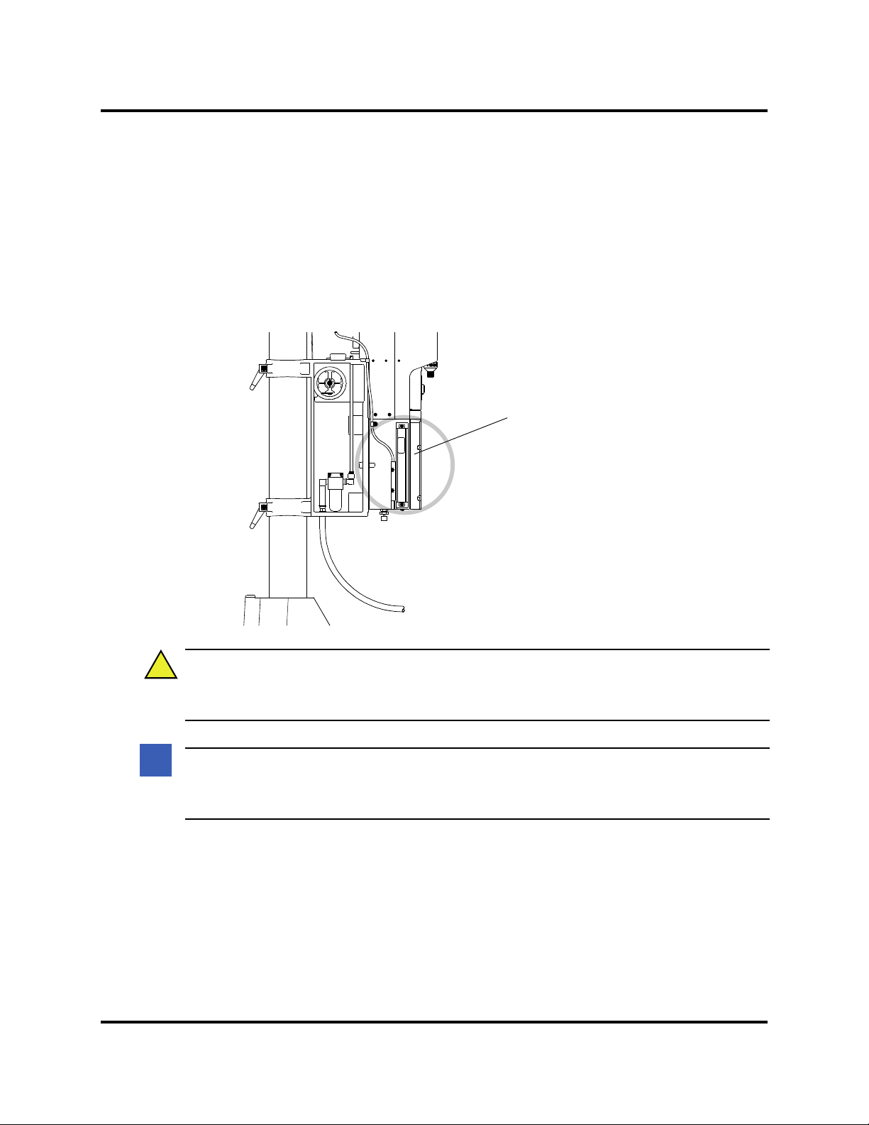
2000X aod Actuator Chapter 4: Installation and Setup
CAUTION
!
NOTE
i
i
Linear Encoder
on left side of
Actuator
Do not touch, bump,
or use as a handle
Actuator on stand shown,
left side view
Instruction Manual Handling and Unpacking
4.2.1 Unpack the Stand or Actuator
The stand (or actuator) is heavy and packed in a protective shipping container. The actuator toolkit is packed
with the actuator. A booster, converter and other components may be packed inside the shipping container
(depending on the equipment ordered).
• Stands are shipped on a wooden pallet with a cardboard box cover.
• Actuators (alone) are shipped in a rigid cardboard box using protective foam shells for support.
Figure 4.1 Linear Encoder is Sensitive; Do Not Handle it!
The linear encoder (on the left side of the actuator) is very sensitive. Do not use the linear
encoder assembly as a hand-hold, allow no impact on it, and do not place any weight on it.
It might be occasionally necessary to clean the non-contact encoder. Use a q-tip dampened
with alcohol and lightly swab the 2 surfaces that make up the encoder assembly.
Depending on which one of the following options applies to you, unpack the Branson actuator assembly:
100-214-282 Rev. 07 4-3

Chapter 4: Installation and Setup
CAUTION
!
CAUTION
!
wood block
for shipping
Actuator
Column
Base
Actuator
Support
Spring Swivel
Tool Kit
Converter
Booster
18in.
Protective
Box
wood block
for shipping
53in.
32-1/2in.
Insert
Box
Handling and Unpacking
4.2.2 Stand (actuator on a base)
Heed the “This End Up” arrows and the “Open Top First” instructions. The packaging is
designed to be removed from the assemblies from an upright orientation only.
Figure 4.2 Unpacking the Stand (Actuator on a Base); Right-side View of Stand
1. Move the shipping container close to the intended installation location, leave it on the floor.
2. Open the top of the box. Remove the insert from the top of the protective box, which may contain
the booster, converter, and the toolkit.
3. Remove the staples at the bottom of the protective box. Lift the protective box off the pallet.
4-4 100-214-282 Rev. 07
The column and column support are under spring tension from the counterbalance spring. Do
NOT attempt to disassemble the column from the stand, but always keep the column support
clamped together. When making height adjustments, carefully and slowly release the clamps
to control the motion, and hold the stand to prevent sudden movements or injury.
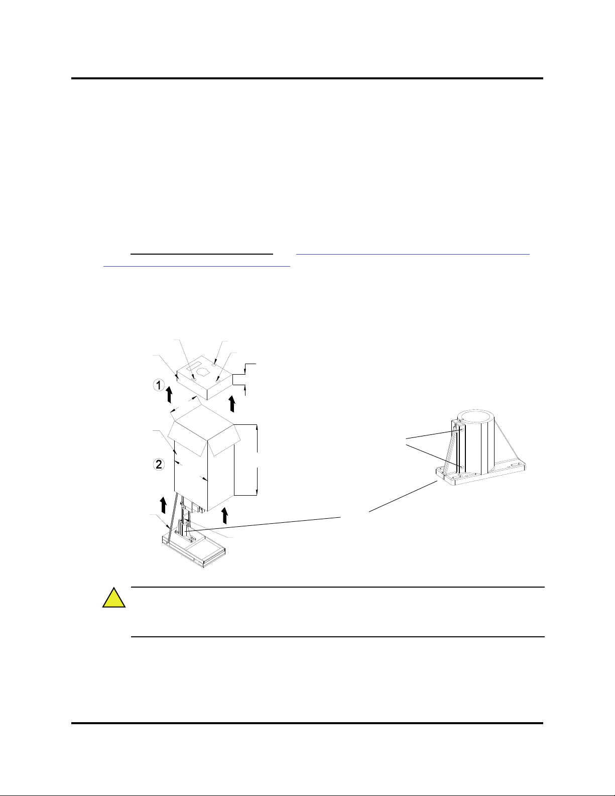
2000X aod Actuator Chapter 4: Installation and Setup
CAUTION
!
Converter
Tool K i t
Booster
6-1/2in.
18in.
Shipping
Strap
53 in.
Block of wood
for shipping
32-1/2in.
Insert Box
Protective
Box
Hub
(shipped in place
on column, on pallet)
Two Hub Bolts
(loosen to remove
Hub from Column)
Note: Hubs may be lag-bolted to the
pallet for shipping purposes.
Instruction Manual Handling and Unpacking
4. Cut the two packing straps around the base and pallet. Pry off the two wooden shipping blocks (to
the rear of the base) which prevent the base from sliding on the pallet.
5. The stand can now be moved into its desired location by sliding it off the pallet. Stands have a lifting
hook for the use of overhead hoists to lift the assembly in place.
6. Remove the block of wood between the base and the column support by carefully loosening the
two column clamps (allowing the actuator to rise slightly, but not allow sudden movements) and
then cutting the shipping tape on the block of wood. RETIGHTEN THE COLUMN CLAMPS.
7. Unpack the toolkit from the insert box, and other parts (converter, booster, etc.) that may have
shipped with the stand. Save the packing material.
8. Go to Take Inventory of Small Parts.
and/or Actuator Assemblies’ on page 4 - 7.
See Table 4.1 ’Small Parts included (=x) : Power Supply
4.2.3 Stand (Actuator on a Hub)
Figure 4.3 Unpacking the Stand (Actuator on a Hub); Hub Shown Separately
Heed the “This End Up” arrows and the “Open Top First” instructions. The packaging is
1. Move the shipping container close to the intended installation location, leave it on the floor.
100-214-282 Rev. 07 4-5
designed to be removed from the assemblies from an upright orientation only.

Chapter 4: Installation and Setup
CAUTION
!
CAUTION
!
NOTE
i
i
Handling and Unpacking
2. Cut the two vertical packing straps, and open the top of the box. Remove the insert from the top of
the box, which can contain the booster, converter, and the toolkit. Set the insert box aside.
3. Remove the staples at the bottom of the protective box. Lift the protective box off the pallet. Flatten
the box and lay it next to the pallet (you will lay the stand on it soon).
The unit may tend to tip over. Stabilize the stand using the lifting hook or an assistant.
4. Cut the packing strap securing the column support to the pallet.
The column and column support are under spring tension from the counterbalance spring. Do
NOT attempt to disassemble the column from the stand, but always keep the column support
clamped together. When making height adjustments, carefully and slowly release the clamps
to control the motion, and hold the stand to prevent sudden movements or injury.
5. Remove the block(s) of wood between the base and the support by slowly loosening the two column
clamps (allowing the stand to rise slightly) and then cutting the shipping tape on the block of wood.
RETIGHTEN THE COLUMN CLAMPS.
6. Loosen the two hub bolts (for column clamping) on the hub.
7. Lift the actuator and column from the pallet. Carefully lay the stand on its right side (NOT ON THE
SIDE WITH THE LINEAR ENCODER).
8. Remove the hub from the pallet and set it aside. Some hubs are bolted to the pallet from the top.
9. Unpack the converter, booster and toolkit from the insert box. Save the packing material, including
the blocks of wood.
10. Go to Take Inventory of Small Parts
and/or Actuator Assemblies’ on page 4 - 7.
. See Table 4.1 ’Small Parts included (=x) : Power Supply
4.2.4 Actuator (Alone)
The actuator, if shipped alone, is assembled and ready to install.
Move the shipping container close to the intended installation location, leave it on the floor.
11. Open the top of the cardboard box, remove the insert from the top of the box and set it aside.
12. The toolkit, mounting bolts, and converter and/or booster are shipped with the actuator but in separate shipping box(es). Unpack the converter, booster, toolkit and bolts from their packages.
13. Save the packing material.
The packaging may also include the converter and/or booster, if ordered.
4-6 100-214-282 Rev. 07

2000X aod Actuator Chapter 4: Installation and Setup
Booster
Converter
(J-type shown)
Instruction Manual Take Inventory of Small Parts
Figure 4.4 Ultrasonic Converter (J-Type for Stand-Alone Use) and Booster
4.3 Take Inventory of Small Parts
Table 4.1 Small Parts included (=x) : Power Supply and/or Actuator Assemblies
2000X Power Supply
Part or Kit
Actuator
20kHz 30kHz 40kHz Stand (Base) Stand (Hub) (alone)
T-Handle Wrench x x x
Mylar Washer Kit x x
Silicone Grease x
Actuator Mtg. Bolts x
20kHz Spanners (2) x
30kHz Spanners (2) x
40kHz Spanners (2) x
40kHz Sleeve ordered part ordered part ordered part
40kHz Sleeve Spanner ships w/ Sleeve ships w/ Sleeve ships w/ Sleeve
Fixture Bolts and
Washer
M8 Allen Wrench x
T-Handle Wrench, Micro
Actuator, 5/32 in
x
xx*x
100-214-282 Rev. 07 4-7

Chapter 4: Installation and Setup
Take Inventory of Small Parts
4.3.1 Cables
Two cables connect the power supply and actuator: the actuator interface cable, and the RF cable. If the system is to be automated, you may also need a J911 start cable and a user I/O cable. Check your invoice for
cable types and cable lengths.
Table 4.2 List of Cables
101-241-202 Remote Pneumatic (RP) Package Cable (J924), 8’
101-241-203 Actuator Interface, 8’ (J925S)
101-241-204 Actuator Interface, 15’(J925S)
101-241-205 Actuator Interface, 25’(J925S)
101-241-206 Actuator Interface, 50’(J925S)
101-241-207 Alarm I/O, 8’(J957S)
101-241-208 Alarm I/O, 15’(J957S)
101-241-209 Alarm I/O, 25’(J957S)
101-241-258 Alarm I/O, 50’(J957S)
101-240-020 Start Cable (J911) 8’ (req PLA)
101-240-015 Start Cable (J911) 15’ (req PLA)
101-240-010 Start Cable (J911) 25’ (req PLA)
101-240-168 Start Cable (J911) 50’ (req PLA)
101-240-072 Start Cable (J913) 25’ (no PLA req)
101-240-017 RF, non-CE - 8’ (J931S)
101-240-012 RF, non-CE - 15’ (J931S)
101-240-007 RF, non-CE - 25’ (J931S) Note: Not for 30kHz or 40kHz systems
101-240-200 RF, non-CE - 50’ (J931) Note: Not for 30kHz or 40kHz systems
101-240-034 RF, non CE - 8’ (J 934)
101-240-035 RF, non CE - 15’ (J934)
101-240-081 RF, non CE - 8’ (J936S)
101-240-069 RF, non CE - 15’ (J936S)
101-240-080 RF, non CE - 25’ (J936S)
101-240-176 RF, CE - 8’ (J931CS)
101-240-177 RF, CE - 15’ (J931CS)
101-240-178 RF, CE - 25’ (J931CS) Note: Not for 30kHz or 40kHz systems
101-240-199 RF, CE - 50’ (J931C)
101-240-179 RF, CE - 8’ (J934C)
101-240-188 RF, CE - 15’ (J934C)
101-240-182 RF, CE - 20’ (J934C)
100-246-630 Ground Detect Cable
100-143-043 Printer, 6’
4-8 100-214-282 Rev. 07

2000X aod Actuator Chapter 4: Installation and Setup
WARNING
!
NOTE
i
i
Instruction Manual Installation Requirements
4.4 Installation Requirements
4.4.1 Location
The actuator or stand may be installed in a variety of positions. The stand (on a base) is often manually operated, using its base-mounted start switches, and so is installed at a safe and comfortable workbench height
(approximately 30-36 inches) with the operator sitting or standing in front of the system. Stands (on hubs)
are often used in automated systems and may be manually or automatically loaded and unloaded.
The stand may tip over if moved around the axis of its column, if not properly secured. The
work surface on which a stand is installed must be sturdy enough to support it, and secure
enough to not tip over when the stand is adjusted during installation or setup.
The remote box may be located up to 25 feet away from the Actuator.The power supply can be located up
to 50' away for the 20kHz, (20' for 30kHz, and 15' for 40kHz models) from the actuator. The power supply
must be accessible for user parameter changes and settings, and must be placed in a horizontal orientation.
The power supply should be positioned so it does not draw in dust, dirt or material via its rear fans. Refer
to the illustrations on the pages that follow for a dimensional drawing of each component. All dimensions
are approximate and may vary between models:
Figure 4.6
Figure 4.5’Power Supply Dimensional Drawing’on Page12
Figure 4.8’Base Mounting Centers’on Page17
’aod Actuator Dimensional Drawing’ on page 4 - 13
The Remote Interface Box on the 4 AODM Micro Actuator can be located at a maximum of 3
feet from the actuator.
4.4.2 Environmental Specifications
Table 4.3 Environmental Specifications
Environmental Concern Acceptable Range
Humidity 30% to 95%, non-condensing
Ambient Operating Temperature +5°C to +50°C (41°F to 122°F)
Storage / Shipping Temperature
-25°C to +55°C (-13°F to +131°F);
Up to +70°C (+158°F) for 24 hours
100-214-282 Rev. 07 4-9

Chapter 4: Installation and Setup
Installation Requirements
4.4.3 Electrical Input Power Ratings
Plug the Power Supply into a single-phase, grounded, 3-wire, 50 or 60 Hz power source. Table 4.4 lists the
current and fuse ratings for the various models.
The ground screw on the rear of the actuator must be connected to earth ground with #8 gauge wire.
Table 4.4 Input Power requirements
1250 W 200V - 240V 7 Amp Max. @ 200V / 20 Amp fuse NEMA L6-20P Plug
For 20 kHz models
For 30 kHz models
For 40 kHz models
1250 W 100V - 120V 14 Amp Max. @ 100V / 20 Amp fuse NEMA 5-15P Plug
2500 W 200V - 240V 14 Amp Max. @ 200V / 20 Amp fuse NEMA L6-20P Plug
4000 W 220V - 240V 25 Amp Max. @ 220V / 25 Amp fuse NEMA L6-20P Plug
750 W 100V - 120V 10 Amp Max. @ 100V / 20 Amp fuse NEMA 5-20P Plug
750 W 200V - 240V 5 Amp Max. @ 200V / 20 Amp fuse NEMA L6-20P Plug
1500 W 100V - 120V* 26 Amp Max. @ 100V / 20 Amp fuse NEMA 5-20P Plug
1500 W 200V - 240V 10 Amp Max. @ 200V / 20 Amp fuse NEMA L6-20P Plug
400 W 200V - 240V 3 Amp Max. @ 200V / 20 Amp fuse NEMA L6-20P Plug
400 W 100V - 120V 5 Amp Max. @ 100V / 20 Amp fuse NEMA 5-15P Plug
800 W 200V - 240V 5 Amp Max. @ 200V / 20 Amp fuse NEMA L6-20P Plug
800 W 100V - 120V 10 Amp Max. @ 100V / 20 Amp fuse NEMA 5-15P Plug
* requires a special 20 amp 120V receptacle
4-10 100-214-282 Rev. 07

2000X aod Actuator Chapter 4: Installation and Setup
Instruction Manual Installation Requirements
4.4.4 Air Cylinder Consumption
Cubic Feet of air per minute per inch of stroke length (each direction)
Air
Pressure
1.5" 0.00174 0.00243 0.00312 0.00381 0.00450 0.00513 0.00590 0.00660 0.00730 0.00800
2" 0.00317 0.00437 0.00557 0.00677 0.00800 0.00930 0.01040 0.01170 0.01300 0.01420
2.5" 0.00490 0.00680 0.00870 0.01060 0.01250 0.01440 0.01630 0.01830 0.02040 0.02230
3" 0.00680 0.00960 0.01240 0.01520 0.01800 0.02080 0.02350 0.02670 0.02910 0.03190
10 20 30 40 50 60 70 80 90 100
Use the table above to calculate the air used by the air cylinder.
Add 0.034 cubic foot per second (2CFM) of actual weld time to account for converter cooling air
per weld cycle.
Example:
3.0" aed actuator running at full pressure (100psi) and stroke length (4") at a cycle rate of 20 parts
per minute = 0.0319 CFM per inch of stroke (from table) x 8" (total stroke is 4" down and 4"
back) equals 0.2552 CFM per stroke.
Weld time is 1 second so: 0.034 x 1 = 0.034 CFM for cooling.
Add 0.2552 CFM for cylinder to 0.034 CFM for cooling equals 0.2892 CFM per cycle.
Multiply by 20 (parts per minute) for a total of 5.784 CFM.
The example
above is to be considered a worst case condition for a welder to run at.
The 2000X force welding system is unique since it’s pneumatics are used in a differential mode of
operation. For this reason, use the 1000psi values from the above table to be on the conservative
side for sizing airflow, rather than on the actual force values. Be sure to add the converter cooling
value, 0.034.
100-214-282 Rev. 07 4-11

Chapter 4: Installation and Setup
0.45”
11. 4mm
13.4”
340.1mm
17.55”
445.8mm
1.7”
43.6mm
20.6”
522.9mm
Air outlet is under
front panel
5.0” (127mm)
Desired Clearance
Air Intake
5.2”
132.4mm
5.7”
144.8mm
Installation Requirements
Figure 4.5 Power Supply Dimensional Drawing
4-12 100-214-282 Rev. 07

2000X aod Actuator Chapter 4: Installation and Setup
SECTION A-A
BASE (OPTIONAL)
43.0
1092mm
machined mounting
surfaces (3 places)**
**These three mounting surfaces are flat
within 0.004 in. (0.1mm) TIR, in a tolerance
zone of 16 x 3.5 in. (410 x 90 mm). The
surface to which the actuator is mounted
must also have the same flatness tole rance.
Instruction Manual Installation Requirements
Figure 4.6 aod Actuator Dimensional Drawing
100-214-282 Rev. 07 4-13

S-BEAM
SHIELD
EXCIATION(-)
SENSE(-)
SENSE(+)
EXCIATION(+)
AGND (+)
SENSE(-)
5
4
3
5
4
3
SENSE(+)
+10V
J67
P67
212
1
+5VSRC
CARRIAGE
DOOR
PRESENT
ULSSRC
EXTLSSRC
N/C
N/C
SVSRC
PB2_RTN
E_STOP_ RTN
PB1_RTN
EXT_LS_SIG
24VRTN
+24VSRC
+24VSRC
E_STOP_SRC
ULS_SIG
+24VSRC
1
2
3
1
2
3
1
2
3
1
2
3
24VRTN
SENOUT
+24VSR C
PRCNT
SV4RTN
SV4SRC
SV3RTN
SV3SRC
SV2RTN
SV2SRC
SV1RTN
SV1SRC
RTN
PLRTN
PLSRC
ULSSIG
24VRTN
SV1SRC
SV1RTN
SV3SRC
SV3RTN
24VRTN
PRCNT
24SRC
SENOUT
+10V
AGND
LC_SIG_IN
24VSRC
24VRTN
PRCNT
SENOU T
24VRTN
SV1SRC
SV3RTN
SV3SRC
PLRTN
PLSRC
SV1RTN
24VSRC
DGND
ESTOPRTN
ESTOPRTN
ESTOPSRC
ESTOPSRC
PB1RTN
PB2RTN
24VSRC
24VSRC
24VRTN
SV1RTN
SV3RTN
SV1SRC
24VRTN
EXTLSSIG
SV1 PRIMA RY
(AEF ONLY)
LINEAR
ENCODER
SV2 (FUTURE)
(AO ON LY )
(AO ON LY)
INTERFACE
PC BOARD
MAX CABLE LENGT H IS 25'
REMOTE VALVE PACKAGE
DISTRIBUTIO N
PC BOARD
PROPORTION AL
VALVE
3443
15
14
13
12
11
10
9
8
7
6
5
4
3
2
1
1
2
3
4
5
6
7
8
9
10
11
12
13
14
15 N/C
N/C
N/C
N/C
N/C
J66-B
J62-B
J63-B
1
5
1
5
2
1
P66
2
1
2
1
P62
2
1
2
1
J82
2
1
P63
2
1
2
1
J81
1
0
1
0
9
9
8
8
7
7
6
6
2
2
3
3
1
4
5
5
P85
1
4
J85-B
P
8
5
SV3 CCV
SV1
PRIMARY
PILOT
LIGHT
1
1
1
1
1
2
1
3
1
4
1
4
1
3
1
2
J64-B
P64
2112
PROPORTIONAL
VALVE
(AEF ONLY)
SV3 CCV
(AEF ONLY)
121
2
J71P71
N/C
PILOT
LIGHT
DGND
P77
J61-A
J62-A
J63-A
J64-A
J65-A
J66-A
J69-A
J70-A
A+
B+
CASE
AB-
9
8
7
6
5
4
3
2
11
P70
2
3
4
5
6
7
8
9
N/C
11
P69
22
66
77
8998
3
4
5
3
4
5
J
8
5
-
A
2
3
10
11
12
13
14
15
16
17
18
19
20
21
22
23
24
25
26
27
28
29
30
31
32
33
34
35
36
37
J60
1
2
3
4
5
6
7
89CS_D/A+
A-
B-
RXTXCS_A/D-
A+
B+
S_CLK+
RX+
TX+
CS_A/D+
S_CLK-
CS_D/A-
J75-A
CS_DIG+
CS_DIG-
N/C
N/C
N/C
1
J72
A
B
C
RF OUT
RF RTN
231
1
2
3
P66
1
2
3
1
2
3
4
1
2
3
P61
1
2
3
1
2
P65
1
2
1
2
P79 J79
1
2
P73 J73
PAL M BUT TON STAR T
AUTOMATION S TART
PB1
PB2
PB1PB2
REF
ULS
VOLT(REG)
OUT SIG
10V RET
+10V SRC
CONVE RTER
LOAD CEL L
100-246-891
G
D
S
(
O
P
T
I
O
N
A
L
)
A
C
T
U
A
T
O
R
I
N
T
E
R
F
A
C
E
A
C
T
U
A
T
O
R
R
E
A
R
P
A
N
E
L
SV4 (FUTURE)
EMER
STOP
EMER
STOP
Chapter 4: Installation and Setup
Installation Requirements
Figure 4.7 Block Wiring Diagram
4-14 100-214-282 Rev. 07

2000X aod Actuator Chapter 4: Installation and Setup
WARNING
!
Instruction Manual Installation Requirements
4.4.5 Factory Air
The factory compressed air supply must be “clean (to a 5 micron level), dry and unlubricated” air with a
regulated maximum pressure of 100 psig (690 kPa). Depending on your application, the actuator requires
between 35 to 100 psi. Stands include an in-line air filter. Actuators (alone) require a customer-provided air
filter. A quick-disconnect fitting is suggested. Use a lockout device on the air line if required.
4.4.5.1. Air Filter
Actuators (alone) require a customer-provided air filter which protects from particulate matter of 5 microns
or larger. If a stand is mounted in a position other than upright (vertical), its air filter must be relocated and
oriented so its bowl is the lowest point, and the air flow across the air filter is horizontal. This may require
some re-plumbing of the existing equipment at the customer site. The air filter is held in place by two screws
on a bracket bolted to the column support, and by the factory-installed tubing. For further information, see
your Actuator manual.
4.4.5.2. Pneumatic Tubing and Connectors
Actuator assemblies are not externally plumbed from the factory, but provide conventional 1/4-inch OD
pneumatic tubing connection at the air inlet. If making connections for an actuator, or if re-plumbing your
system for a new air filter location, you must use 1/4-inch OD tubing and connectors rated above 100 psi
(use Parker "Parflex" 1/4 OD x .040 wall, type 1, grade E5, or equivalent), and appropriate connectors.
4.4.5.3. Pneumatic Connections to Actuator
Pneumatic connections to the aod actuator are identified as cylinder top, cylinder bottom, and cooling. The
remote box houses the main air inlet along with the 3 output air connections to the actuator.
Filtered cooling air must be provided to the actuator either from the rp box or from the customers custom pneumatics. Failure to connect cooling air may void product warranty. Consult
with a Branson representative if you have any questions.
You must provide an air filter assembly to the remote box which will support at least 100 psig and remove
particulate matter of 5 microns or larger.
100-214-282 Rev. 07 4-15

Chapter 4: Installation and Setup
WARNING
!
CAUTION
!
CAUTION
!
Installation Steps
4.5 Installation Steps
This product is heavy and can cause a pinching or crushing injury during installation or adjustment. Keep clear of moving parts and do not loosen clamps unless directed to do so.
If a stand is not mounted in a vertical position, the air filter (on the column support) must be
removed, reoriented, and replumbed. Failure to do so can cause air filter failure, and actuator
failures.
4.5.1 Mounting the Stand (Actuator on Base)
The base must be bolted to your workbench to prevent tipping or undesired movement. Four mounting bolt
holes are provided at the corners of the casting, and will accept your 3/8 inch or M10 cap screws. Use flat
washers against the metal casting to prevent gouging.
You must secure the base to your work surface using four bolts, to prevent tipping or undesired movement, in the event the actuator is moved off-center or rotated around the column.
1. Ensure there are no overhead obstructions and that no pinch or rub points exist. Remember that
the actuator is taller than the column when fully raised, and there are exposed connections.
2. Mount the base to your workbench using four socket-head cap screws (customer provided, 3/8 inch
or M10). Use flat washers against the metal casting to prevent gouging. The use of nylon lock nuts
with your cap screws is suggested, to reduce loosening due to vibration and movement.
3. Connect factory air to the air hose on the stand (3/8 NPT male fitting on the hose). A quick-disconnect fitting is suggested. Use a lockout device on the air line if required.
4. Verify the base/start switch control cable is properly connected to the back of actuator.
5. Verify the linear encoder connector is properly connected to the back of the actuator.
6. Verify earth ground is connected with #8 gauge wire to the ground terminal on the rear of the
actuator.
4-16 100-214-282 Rev. 07

2000X aod Actuator Chapter 4: Installation and Setup
CAUTION
!
21.31 in / 541 mm
Mounting Holes
accept 3/8 inch
or metric M10
cap screws
14.75 in /
375 mm
7.37 in /
187 mm
16.5 in /
419 mm
M10
M
28.0 in / 711 mm
Instruction Manual Installation Steps
Figure 4.8 Base Mounting Centers
4.5.2 Mounting the Stand (Actuator on Hub-mounted column)
During unpacking, you removed the hub from the column/stand assembly. You must choose a mounting
location for the hub that will support the column and actuator, and provide the hardware to mount it. Four
mounting bolt holes are provided at the corners of the casting, and will accept your 3/8 inch or M10 hardware. Use flat washers against the metal casting to prevent gouging.
100-214-282 Rev. 07 4-17
The hub must be installed with its front in the same direction as the front of the actuator. The
column bolts of the hub are found on the rear of the hub. See Section Figure 4.9, Mounting
Bolt Pattern for the Hub (for Stand on Hub), on page 4-18 for mounting details.

Chapter 4: Installation and Setup
CAUTION
!
10.50 in / 267 mm
6.00 in / 152 mm
5.25 in / 133 mm
0.94 in / 24 mm
(four places)
3.25 in /
83 mm
4.44 in /
113 m m
3.94 in / 100mm
2.22 in /
56 mm
0.59 in /
11 mm
3/8 inch or
M10 bolts
Front of Hub
Column
Bolts
(4 places)
Jack Screws(4)
Front of Hub
Rear of Hub
2.845 in.
6.270 in.
1.699 in.
Installation Steps
Figure 4.9 Mounting Bolt Pattern for the Hub (for Stand on Hub)
1. Locate the hub in the desired location. Ensure no overhead or side obstructions will interfere with normal
operation or use of the system.
Mount the hub to your work surface using four bolts,
3/8-inch or M10 shank size, with flat washers
against its metal casting (customer provided hardware).
2. Carefully lift the actuator and column assembly, and mount
the column in the hub. Align the flat face of the spring
swivel with the top-front of the actuator. Tighten the two
bolts on the hub.
3. Connect factory air to the air hose on the stand (1/4 NPT
male fitting on the hose). A quick-disconnect fitting is suggested. Use a lockout device on the air line if required.
4. Verify the base/start switch control cable is properly connected to the back of actuator.
5. Verify the linear encoder connector is properly connected
to the back of the actuator.
6. Use jack screws to fine adjust the system level. A 3/16"
allen wrench should be used for the 3/8"-16 x 3/4" jack
screws.
7. Verify earth ground is connected with #8 gauge wire to the
ground terminal on the rear of the actuator.
4-18 100-214-282 Rev. 07

2000X aod Actuator Chapter 4: Installation and Setup
CAUTION
!
CAUTION
!
CAUTION
!
For 12 mm
Dowel Pin
.477
M10 x 1.5 THDS
10 mm deep
(3 places)
4.25
108 mm
8.50
216 mm
14.30
363 mm
15.63
397 mm
50
13 mm
Machined mounting
surfaces (3 places)**
Rear view of ae/aed actuator is shown. Although
other actuators will vary in hei ght, referenced
dimensions wil l be the same for all models.
**These thre e mounting surfaces are flat
within 0.004 in. (0.1mm) TIR, in a tolerance
zone of 16 x 3.5 in. ( 410 x 90 mm). The
surface to which the actuator is mounted
must also have the same flatness tol erance.
Instruction Manual Installation Steps
4.5.3 Actuator (Alone)
The actuator (alone) is intended for installation on your custom-made mounting support.
For the standard AOD Actuator, it is located in place with a mounting pin and secured using three metric
bolts.
1. Lift the actuator from the box. Carefully lay the assembly on its right side (NOT on the side with the
linear encoder).
2. Use of a guide pin is suggested. It is not provided with the actuator. If you require a guide pin, use
a solid metal dowel pin, 12mm diameter, which must not extend into the actuator more than 0.40
inch (10mm) from your support.
The actuator support bolts for the 2000X-Series actuators are metric, M10 x 1.5 thread pitch,
25mm long. The support pin and mounting bolts must not extend more than 0.40 in (10 mm)
into the actuator, otherwise, binding or damage to the carriage may occur.
DO NOT use 900-Series M10 x 1.25 mounting bolts. They have a different thread pitch and
will not interchange with those used on the 2000X-Series
Figure 4.10 Rear view of Actuator, showing Mounting Surface, Bolt and Guide Pin locations
3. Lift the actuator assembly into position on your mount, and secure using the metric bolts provided.
100-214-282 Rev. 07 4-19
In the event you must use bolts of a different length, ensure that the bolts extend more than
0.25 inch (6 mm) into the threads in the actuator housing, but less than 0.40 inch (10 mm).
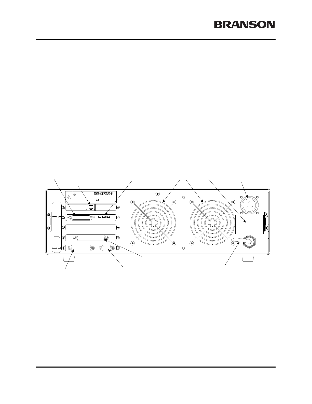
Chapter 4: Installation and Setup
Fans
RF Connector
(ultrasonic energy out)
Power Cord
Parallel Printer Connector
Actuator Interface Connector
Model Data Tag
Serial Port (RS-232) Connector for Host Computer
USER I/O
J3 SW1
ACTUAT OR
SIGNALS
J7
HOST
TERM
J9 J8
MODEL
PRINTER
THIS EQUIPMENT COMPLIES WITH
F.C.C. REGUL ATIONS PART 18
EDP NO.
WARNING
THIS EQUIPMENT COMPLIES WI TH
F.C.C. REGULATIONS PART 18
GROUP 2 CLASS A ISM
ULTRASONICS CORPOR ATION
41 EAGLE ROAD, DANBU R Y, CT 06813-1961
MAX POWER
Serial No.
Year & Month of Manufacture
INPUT
DIP Switch for User I/O
Ethernet Connector (Optional)
Installation Steps
4.5.4 Mount the Power Supply
The power supply is designed to be placed on a workbench (rubber feet on bottom) within cable-length limits of the actuator, or it may be rack-mounted in a standard 19-inch Rack (using an optional rack mount handle kit). It has two rear-mounted fans which draw cooling air from rear to front, which must be free from
obstruction. Do not place the power supply on the floor or in other locations that will allow dust, dirt or contaminants to be drawn into the power supply.
The controls on the front of the power supply must be accessible and readable for setup changes.
All electrical connections are made to the rear of the power supply, which should be positioned in your
workspace with adequate clearance (approximately 4 inches or more on either side, and 6 inches to the rear)
for cable access and ventilation. Do not place anything on top of the power supply case.
In the event the system is to be installed in a high dust environment, the use of a fan filter kit (101-063-614)
is required.
See Figure 4.5 on page -12
Figure 4.11 Connections on Rear of Power Supply
for a dimensional drawing of the 2000d Power Supply.
The cable lengths are limited based on the operating frequency of the welding system. Performance and
results can suffer if the RF cable is crushed, pinched, damaged or modified. Contact your Branson Representative if you have special cable requirements. In some cases, remote operation from a User I/O or a Host
Terminal can be used to solve a distance limitation.
4-20 100-214-282 Rev. 07

2000X aod Actuator Chapter 4: Installation and Setup
WARNING
!
Instruction Manual Installation Steps
4.5.5 Input Power (Main)
The system requires single-phase input power, which you connect to the Power Supply using the integral
power cord. Nominal 120 volt units have a NEMA5-15P plug on the cord, and nominal 200-240 volt units
come with a twist-type locking connector, supplied in the box with the Power Supply. An exception to this
is the 120 volt 30kHz, which has a NEMA5-20 loose plug.
Refer to the unit’s Model Data Tag to be sure of the power rating of the Model in your system.
4.5.6 Output Power (RF Cable)
Ultrasonic Energy is delivered to a screw-on MS receptacle connection on the rear of the Power Supply,
which is connected to the Actuator or the Converter (depending on your application).
Never operate the System with the RF Cable disconnected or if the RF Cable is damaged.
4.5.7 Interconnect between Power Supply and Actuator
The Branson 2000Xd Actuator has two electrical connections between the Power Supply and the Actuator:
the RF Cable and the Actuator Interface cable. A 37-pin Actuator Interface Cable is used for Power and
Control Signaling between the Power Supply and a Branson Actuator. The cable connects to the rear of the
Power Supply and the rear of the Actuator.
There can be other connections to the Actuator, and other connections to the Power Supply, but these are the
only two standard connections, depicted in Figure 4.12
For ground detect use, to have ultrasonic energy turn off when the horn comes in contact with your electrically isolated fixture or anvil, it is necessary to install Branson cable EDP No. 100-246-630 from the MPS/
GDS receptacle on the rear of the actuator to your isolated fixture/anvil in order to utilize this feature.
.
100-214-282 Rev. 07 4-21

Chapter 4: Installation and Setup
Actuator Interface Cable
J931
RF Cable
MPS/GDS
Remote Box Cable
Start Switch Cable
Base (shown rotated 90°CCW)
Power Supply,
rear view
Actuator
Linear Encoder Cable
A
C
B
ACB
To R em ot e B o x
Remote Box
Earth Ground
Connector stud
M10 X 1.5 FASTENERS
ACTUATOR USE
FOR MOUNTING OF
THAN 10MM (.4")
ACTUATOR MORE
TO PENETRATE
DO NOT ALLOW BOLT
MPORTANT
SIGNALS
PS
REMOTE
AOP/AO
ENCODER
START
BASE/
BEFORE O PERAT ING
GROUND UNIT
BEFORE SERVICING
DISCONNECT
BRANSON ULTRASONICS CORPORATION
41 EAGLE RD., DANBURY, CT. 06813-1961
MODEL: AEP 430
Made in U.S.A.
101-134-106
YEAR OF MANUFACTURE 1996
IMPORTANT
AIR SUPPL Y MUST BE FR EE O F OI L AND WAT ER
CYLINDER BOTTOM
CYLINDER TOPCOOLING AIR
INLET
AIR
AIR
COOLING
IMPORTANT
COOLING AIR CYLINDER TOP
CYLINDER BOTTO M
AOP/AO R EMO TE
BRANSON
BRANSON ULTRASONICS CORPORATION
41 EAGLE RD., DANBURY, CT. 06813-1961
MODEL: AEP 430
101-134-106
YEAR OF MANUFACTURE 1996
Made in U.S.A.
Installation Steps
Figure 4.12 Electrical Connections from Power Supply to a 2000-series Actuator
4-22 100-214-282 Rev. 07

2000X aod Actuator Chapter 4: Installation and Setup
NOTE
i
i
NOTE
i
i
NOTE
i
i
P69
EMER
STOP
START SWITCHES
PB1PB2
1
2
3
4
5
6
7
PB2RTN
9
8
Color Codes
PB1RTN
PB1SRC
PB2SRC
ESTOPSRC
ESTOPSRC
ESTOPRTN
ESTOPRTN
N/C
Blue
Black
White
Orange
Purple
Yellow
Red
Green
Brown
Instruction Manual Installation Steps
4.5.8 Start Switch Connection (Automation)
A Branson actuator requires two start switches and emergency stop connection. Stands on a base include
this connection (factory installed and connected from the base) while the stand on a hub and actuator (alone)
applications require the user make their own start switch/E-stop connections, as follows:
Figure 4.13 Start Switch Connection Codes
Solid state devices may be used in lieu of mechanical start switches providing their leakage
current does not exceed 0.1mA.
Start Switches PB1 and PB2 must be closed within 200 milliseconds of each other, and
remain closed until the WELD ON signal is active, to effect a start condition.
BASE/START is the DB-9 female connection on the back of the actuator. Your cable requires a male DB-9
(D-shell) connector.
PB1 and PB2 are two normally open start-switches which must be operated simultaneously to start the welding cycle. These must be closed within 200 milliseconds of each other, or error message "Start Sw Time"
will display. This doesn’t require a reset, but for the next cycle, switches must be within time limit to preclude re-occurrence of error message. Refer to Note above.
EMER STOP is an emergency stop switch, normally closed.
Refer to the Branson Automation Guide (EDP 100-214-273) for additional information about
selection and use of Input and Output features.
100-214-282 Rev. 07 4-23

Chapter 4: Installation and Setup
NOTE
i
i
Installation Steps
4.5.9 Serial (RS-232) Port Connector
An RS-232c serial port (DB-9 format) is provided for the Remote Terminal or Host Computer option. Only
three data leads of this port are supported at this time (Data Send, Data Receive, and Signal Ground). The
remainder of the leads are ‘reserved’. A null modem cable is required.
The comport parameters are fixed, can not be altered or viewed in the menu.
The fixed values are:
1. com speed = 9600 baud
2. no parity
3. 1 stop bit
4. 8 data bits
4.5.10 Parallel Printer Connector
The Printer Connector supports several printer models, both dot matrix and ink jet, to provide printed reports
of your weld information, and to provide graphical representation of your weld results. The tractor feed
feature of dot matrix printers is preferred for many manufacturing applications. If necessary, consult your
Branson representative for recommendations for your specific needs.
The printers listed in Table 4.5 have been fully tested to confirm compatibility with Branson products. Printers that were tested and are NOT compatible are the Panasonic 1091 and Epson LX300. The printer interface uses a standard 36-pin Centronics cable (Branson printer cable EDP 100-143-043).
Table 4.5 Printer Compatibility
Manufacturer Model No
Epson LQ-570 FX-980 Stylus 900
Okidata 5340HE 320 Turbo 520**
Panasonic 1180 1150
H-P 610C 540 600
** Includes both off the shelf and Branson supplied units. However, all units excepting the Branson supplied
Okidata 520 may not stop printing when abort is selected in the menu. The data may have been transferred
to the printer and can’t be halted.
Power for the Power Supply and the printer must be OFF before installing the printer cable.
If it is installed with power on, the power supply front panel may lock up.
4-24 100-214-282 Rev. 07
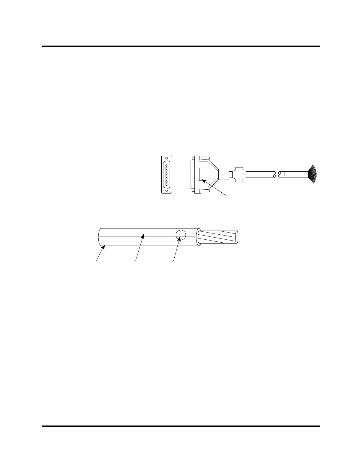
2000X aod Actuator Chapter 4: Installation and Setup
User I/O Cable
Stripped and tinned one end,
HD-44 male connector other end
(cable length as ordered)
Part number
Wire Color Diagram
Two Colors = Insulator/Stripe
Three Colors = Insulator/Stripe/Dot
Insulation Stripe Dot
Instruction Manual Installation Steps
4.5.11 User I/O Interface
The user I/O is a standard interface for automation, provided on the power supply. It provides the ability for
the customer to make their own interface for their automation or special control or reporting needs. The
interface cable has an HD44 female D-shell connection on the rear of the power supply. The electrical interface outputs may be configured for open collector mode or for signal mode (signal voltage levels as indicated), by setting the user I/O DIP switch.
DIP switch SW1 for the user I/O is located next to the J3 on the back of the 2000X-series power supply.
User I/O interface cable pinout is listed in Table 4.5.
Figure 4.14 User I/O Cable Identification and Wire Color Diagram
100-214-282 Rev. 07 4-25

Chapter 4: Installation and Setup
Installation Steps
Table 4.6 User I/O Cable Pin Assignments, Alphabetical Order
Pin Signal Name Signal Type Direction Signal Range Definition Colors
7 ACT_CLEAR 0V True Output 0/24V, 100mA Actuator clear signal Red/Wht
24 AMPLITUDE_OUT Analog Output 0V to 10V Amplitude signal from PS Red/Blk/
2 CYCLE_ABORT 24V True Input 0/24V, 100mA Red/Blk
3 EXT_RESET 24V True Input 0/24V, 100mA System Reset Grn/Blk
18 EXT_SEEK+ 24V True Input 0/24V, 100mA Red/Blk/
38 FREQ_OUT Analog Output -10V to +10V Frequency Signal from PS Blk/Wht/Blu
6 G_ALARM 0V True Output 0/24V, 100mA Blk/Wht
14 GEN_ALARM_RELAY_1 Relay Contact Output 40V, 0.25A Contact Closure Red/Grn
29 GEN_ALARM_RELAY_2 Relay Contact Output 40V, 0.25A Contact Closure Wht/Red/
1 J3_1_INPUT 24V True Input 0/24V, 100mA User definable inputs. Refer
17 J3_17_INPUT 24V True Input 0/24V, 100mA Wht/Blk/
19 J3_19_INPUT 24V True Input 0/24V, 100mA Grn/Blk/
31 J3_31_INPUT 24V True Input 0/24V, 100mA Wht/Red/
32 J3_32_INPUT 24V True Input 0/24V, 100mA Blk/Wht/
33 J3_33_INPUT 24V True Input 0/24V, 100mA Wht/Blk/
8 J3_8_OUTPUT 24V True Output 0/24V, 100mA User definable outputs. Refer
22 J3_22_OUTPUT 24V True Output 0/24V, 100mA Blk/Red/
36 J3_36_OUTPUT 24V True Output 0/24V, 100mA Orn/Red
9 MEM Analog Output -10V to +10V Memory Signal from PS Blu/Wht
11 MEM_CLEAR Open Collector Output 24V, 25mA max Memory Clear signal send toPSWht/Red
to Table 4.6 to view available
selections.
to Table 4.7 to view available
selections.
Grn
Wht
Orn
Wht/Blk
Red
Wht
Blu
Grn
Grn
Grn/Wht
Grn
Grn
40 MEMORY_STORE Open Collector Output 24V, 25mA max Memory store from PS Red/Wht/
Blu
34 PB_RELEASE 0V True Output 0/24V, 100mA Red/Wht/
Grn
37 PWR Analog Output 0V to 10V Power Signal from PS Blu/Red/
21 READY 0V True Output 0/24V, 100mA Blu/Blk/Wht
5 REJECT 0V True Output 0/24V, 100mA Blu/Blk
43 READY_ RELAY_1 Relay Contact Output 40V, 0.25A Contact Closure Blu/Orn/
15 READY_RELAY_2 Relay Contact Output 40V, 0.25A Contact Closure Orn/Grn
26 RUN Open Collector Output 24V, 25mA max Run signal send to PS Orn/Blk/Grn
39 SEEK Open Collector Output 24V, 25mA max Seek Signal send to PS Wht/Blk/Blu
4 SOL_VALVE_SRC 24V Output 0/24V, 125mA SV1 Source Orn/Blk
Grn
Red
4-26 100-214-282 Rev. 07

2000X aod Actuator Chapter 4: Installation and Setup
CAUTION
!
NOTE
i
i
Instruction Manual Installation Steps
Pin
Signal Name Signal Type Direction Signal Range Definition Colors
16 SOL_VALVE_RTN 24V Return Input 0V SV1 Return Blk/Wht/
Red
20 SUSPECT_PART 0V True Output 0/24V, 100mA Orn/Blk/
10 USER_AMP_IN Analog Input -10V to +10V User Amplitude control signal Blk/Red
25 USER_FREQ_OFFSET Analog Input -10V to +10V User Freq. offset control sig-
nal
35 WELD_ON 0V True Output 0/24V, 100mA Start of sonics and trigger Grn/Wht/
30 WELD_ON_RELAY_1 Relay Contact Output 40V, 0.25A Contact Closure Orn/Wht/
44 WELD_ON_RELAY_2 Relay Contact Output 40V, 0.25A Contact Closure Blk/Orn/
23 +10V_REF Analog Output 10.0V 10VDC ref. voltage from PS Wht/Red/
12 24V_RTN 24V Ground Input 0V 24V Return Orn/Red
13 24V_SRC 24V Source Output 24V, 1.25A max 24V Source Blu/Red
27 24V_RTN 24V Ground Input 0V 24V Return Blu/Wht/
28 24V_SRC 24V Source Output 24V, 1.25A max 24V Source Blk/Wht/
41 24V_RTN 24V Ground Input 0V 24V Return Grn/Orn/
42 24V_SRC 24V Source Output 24V, 1.25A max 24V Source Orn/Red/
Wht
Grn/Blk/Orn
Blu
Blu
Red
Grn
Orn
Orn
Red
Blu
Ensure all unused wires are properly isolated. failure to do so may result in Power Supply or
system failure.
Refer to the Branson Automation Guide (EDP 100-214-273) for additional information about
selection and use of Input and Output features listed in the following Table.
100-214-282 Rev. 07 4-27
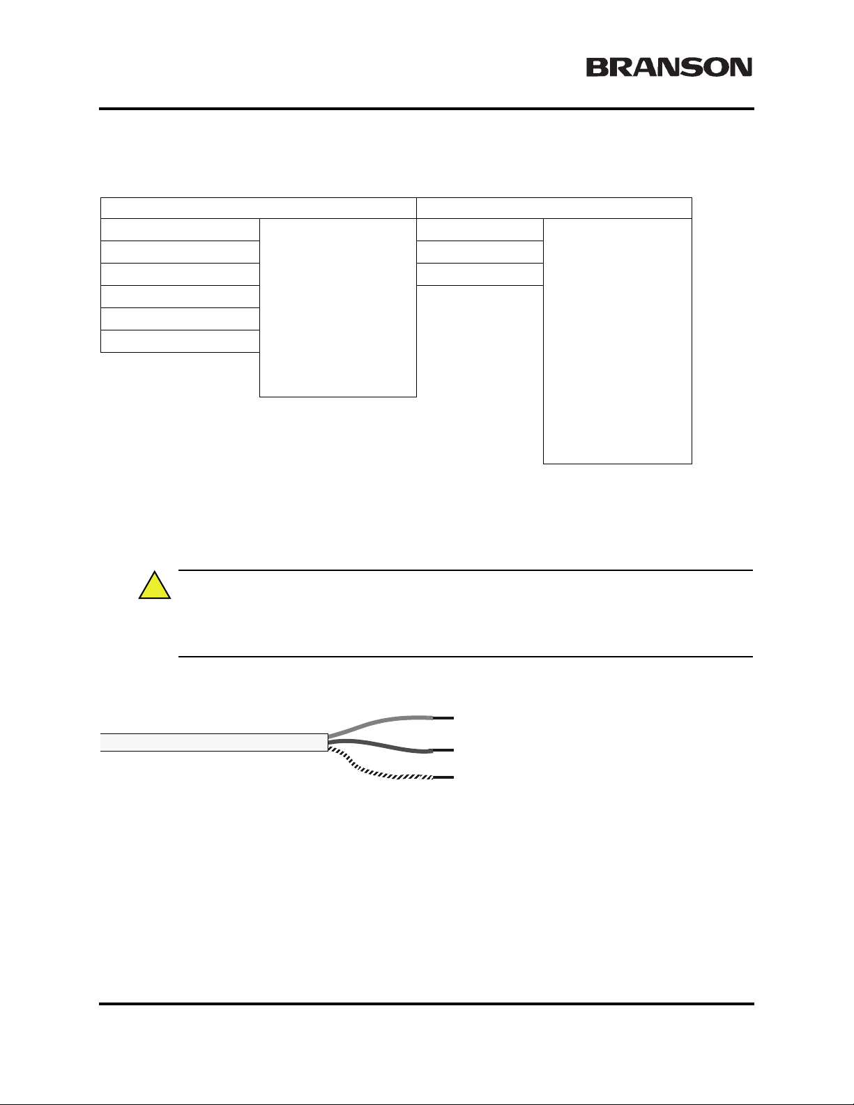
Chapter 4: Installation and Setup
CAUTION
!
BLUE = Neutral 120v operation, Line for 220v
BROWN = Line
GREEN/Yellow trace = Earth Ground
Line Cord jacket
Installation Steps
Table 4.7 User I/O Input and Output Function Selection
Input Output
J3_1_INPUT
J3_17_INPUT J3_22_OUTPUT
J3_19_INPUT J3_36_OUTPUT
J3_31_INPUT
J3_32_INPUT
J3_33_INPUT
Disabled
Ext U/S Delay
Display Lock
Ext Cycle Abort
Sonics Disable
Memory Reset
External Start
Ext Signal
Sync In
J3_8_OUTPUT
Disabled
Confirm Preset
Ext Beeper
Cycle Okay
No Cycle Alarm
Overload Alarm
Modified Alarm
Note
Missing Part
External Start
Sync Out
4.5.12 Input Power Plug
If you must add or change the input power plug, use the following color code for the conductors found in the
international harmonized line cord. Add the plug that is appropriate for your input power receptacle.
The power supply can be permanently damaged if it is connected to the incorrect line voltage,
or if the wiring connection is mis-wired. It also presents a safety hazard if mis-wired. Use of
the correct plug or connector helps prevent incorrect connections.
Figure 4.15 Line Cord Color Code
4-28 100-214-282 Rev. 07

2000X aod Actuator Chapter 4: Installation and Setup
CAUTION
!
WARNING
!
Instruction Manual Installation Steps
4.5.13 User I/O DIP Switch (SW1)
DIP switch SW1 for the user I/O is located next to the J3 on the back of the 2000X-series power
supply. The settings of these switches affect the user I/O signals. Factory default setting is with all
dip switches set to ON (switch position closest to number designation).
• If the dip switch is set to the ON (closed) position, the corresponding Output pin will be configured as
the current source, 25mA max.
• If the dip switch is set to the OFF (open) position, the corresponding Output pin will be configured as an
“open collector”, 24VDC, 25 mA max. current sink.
Table 4.8 User I/O DIP Switch Functions
Switch Position Signal Description Output Signal
1 REJECT_PART R_SIG
2 SUSPECT_PART S_P_SIG
3 PB_RELEASE PB_R_SIG
4G_ALARM G_A_SIG
5 READY RDY_SIG
6WELD_ON W_O_SIG
7 ACTUATOR_RETURN A_R_SIG
8 USER_OUT1 M_PART_SIG
9 USER_OUT2 U_OUT1_SIG
10 USER_OUT3 U_OUT2_SIG
4.5.14 Module Options DIP Switch
In some configurations, it might be necessary to open the Power Supply and change the DIP (Dual In-line
Package) switches on the power supply module. DIP switches change the Seek and Start functions and can
affect the Amplitude Control functions. Refer to your Power Supply Instruction manual, or 2000X-Series
Installation Guide for detailed information.
The components in the Power Supply are subject to damage from electro-static discharge.
When working inside the Power Supply, use a grounded wrist strap and minimize your movement to reduce the possibility of damage due to static electricity.
Unplug the Power Supply (if previously connected) and wait at least two (2) minutes before
opening the Power Supply case. Hazardous Voltages exist and are stored in the system.
100-214-282 Rev. 07 4-29
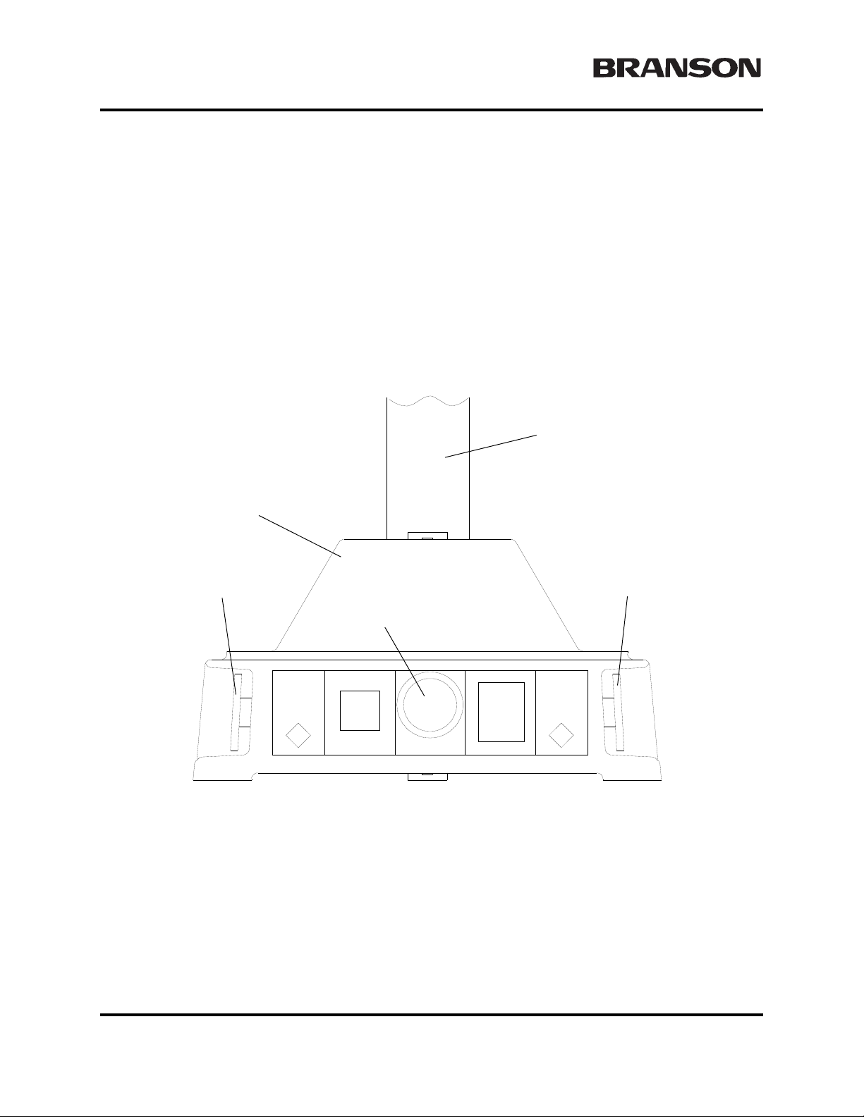
Chapter 4: Installation and Setup
Column
Base
Start SwitchStart Switch
Emergency Stop Knob
Guards and Safety Equipment
4.6 Guards and Safety Equipment
4.6.1 Emergency Stop Control
If you use the Emergency Stop button on the Actuator to terminate a weld, twist the button to reset it. (The
welder will not operate until this button is reset.) You must then press Reset at the power supply. If you are
running automation, you can use external reset that is connected to your User I/O board.
Figure 4.16 Actuator Emergency Stop Button
If you are using an Emergency Stop signal from the User I/O, you must clear the Emergency Stop condition
before the System will operate.
4-30 100-214-282 Rev. 07

2000X aod Actuator Chapter 4: Installation and Setup
NOTE
i
i
Insert two flat-head screws
through the bracket and
into each handle, as shown
Right-side Rack Mount handle
Rack Mount bracket
(right side shown)
Instruction Manual Rack Mount Installation
4.7 Rack Mount Installation
If the system is Rack Mounted, you need to order the Rack Mount handle kit. The kit includes two rack
mounting handles and two corner pieces, which support the handles and provide the rack mount interface.
Do not permanently remove the Cover from the Power Supply because it is required for
proper system cooling.
Figure 4.17 Detail of Rack Mount Handle Kit Assembly
Step Procedure
1
2
3
4
5
6
100-214-282 Rev. 07 4-31
Order and obtain the Rack Mount kit for your Power Supply. The brackets in the Kit are
designed for standard 19-inch rack mounting options.
From the front corners of the Power Supply, remove the Front Corner bezels by removing
the two Phillips screws. Save the screws.
Noting that one side of each bracket is countersunk to accept the provided flathead
screws, assemble the Rack Mount Handles as shown in Figure 4.17
Mount Handle Kit Assembly’ on page 4 - 31. (This shows only the Right bracket and han-
dle; the left side is a mirror-image.) Tighten the screws securely and so they are flush.
Re-using the screws you removed in Step 2, install the assembled Handle in place of the
Front Corner pieces.
Save the removed hardware corner pieces.
When you are ready to install the unit, use the hardware from your Rack Mounting system
to locate the Power Supply.
’Detail of Rack

Chapter 4: Installation and Setup
CAUTION
!
CAUTION
!
Assemble the Acoustic Stack
4.8 Assemble the Acoustic Stack
The following procedure must be performed by a setup person. If necessary, secure the largest portion of a square or rectangular horn in a soft jawed (brass or aluminum) vise. NEVER
attempt to assemble or remove a horn by holding the converter housing or the booster clamp
ring in a vise.
Do not use silicone grease with Mylar washers. Use only 1 (one) Mylar washer of the correct
inside and outside diameters at each interface.
Table 4.9 Tools
Tool EDP Number
20 kHz Torque Wrench 101-063-617
40 kHz Torque Wrench 101-063-618
20 kHz Spanner Wrench 101-118-039
30 kHz Spanner Wrench 201-118-033
40 kHz Spanner Wrench 201-118-024
Silicone Grease 101-053-002
4.8.1 For a 20kHz System
Step Action
1
2
3
4
5 Assemble the converter to the booster and the booster to the horn.
6 Torque to 220 in-lbs, 24.85 Nm.
Clean the mating surfaces of the converter, booster, and horn. Remove any
foreign material from the threaded holes.
Install the threaded stud into the top of the booster. Torque to 450 in-lbs, 50.84
Nm. If the stud is dry, apply 1 or 2 drops of a light lubricating oil before installing.
Install the threaded stud into the top of the horn.Torque to 450 in-lbs, 50.84 Nm.
If the stud is dry, apply 1 or 2 drops of a light lubricating oil before installing.
Install a single Mylar washer (matching the size of the washer to the stud) to
each interface.
4-32 100-214-282 Rev. 07

2000X aod Actuator Chapter 4: Installation and Setup
Instruction Manual Assemble the Acoustic Stack
4.8.2 For a 30kHz System
Step Action
1
2
3
4
5
6 Assemble the converter to the booster and the booster to the horn.
7 Torque to 185 in-lbs, 21Nm.
Clean the mating surfaces of the converter, booster, and horn. Remove any
foreign material from the threaded holes.
Apply a drop of Loctite®
booster and horn
Install the threaded stud into the top of the booster; torque to 290 in-lbs,
32.76Nm, and let cure for 30 minutes.
Install the threaded stud into the top of the horn; torque to 290 in-lbs, 32.76Nm,
and let cure for 30 minutes
Install a single Mylar washer (matching the size of the washer to the stud) to
each interface.
1
290 threadlocker (or equivalent) to the studs for the
1. Loctite is a registered trademark of Henkel Corporation, U.S.A.
4.8.3 For a 40kHz System
Step Action
1
2
3
4
5
6 Screw the converter to the booster.
7 Torque to 95 in-lbs, 10.7Nm.
8
9 Screw the booster onto the horn.
10 Repeat Step 7.
11
Clean the mating surfaces of the converter, booster, and horn. Remove any
foreign material from the threaded holes.
Apply a drop of Loctite 290 threadlocker (or equivalent) to the studs for the
booster and horn.
Install the threaded stud into the top of the booster; torque to 70 in-lbs, 7.9 Nm,
and let cure for 30 minutes.
Install the threaded stud into the top of the horn; torque to 70 in-lbs, 7.9 Nm, and
let cure for 30 minutes.
Coat each interface surface with a thin film of silicon grease –
silicon grease to a threaded stud or tip.
Slide the booster/horn assembly into the adapter sleeve. Screw on the adapter
sleeve ring nut and leave loose.
Securely tighten the adapter sleeve ring nut with the spanner wrenches shipped
with the sleeve assembly.
but do not apply
100-214-282 Rev. 07 4-33

Chapter 4: Installation and Setup
NOTE
i
i
Converter
Booster
Spanner (provided)
Horn
Vise Jaw protectors
(aluminum or soft metal)
See Stack Assembly Procedure
Vise
Assemble the Acoustic Stack
4.8.4 Assembling the 20kHz Acoustic Stack
(Shown with Rectangular Horn Secured in the Vise.)
Figure 4.18 Assembling the 20kHz Acoustic Stack
Stack Assembly Torque Table
The use of a Branson torque wrench or the equivalent is recommended. P/N 101-063-617 for
20kHz systems and 101-063-618 for 40kHz systems.
Table 4.10 Stud Torque Values
Used On Stud Size Torque EDP #
20 kHz 1/2” x 20 x 1-1/4” 450 in.-lbs, 50.84 Nm. 100-098-370
20 kHz 1/2” x 20 x 1-1/2” 450 in.-lbs, 50.84 Nm. 100-098-123
30 kHz * 3/8” x 24 x 1” 290 in.-lbs, 32.76 Nm. 100-298-170
40 kHz * M8 x 1.25 70 in.-lbs, 7.90 Nm. 100-098-790
* Add a drop of Loctite 290 threadlocker to the stud. Torque and let cure for 30 minutes before use.
4-34 100-214-282 Rev. 07
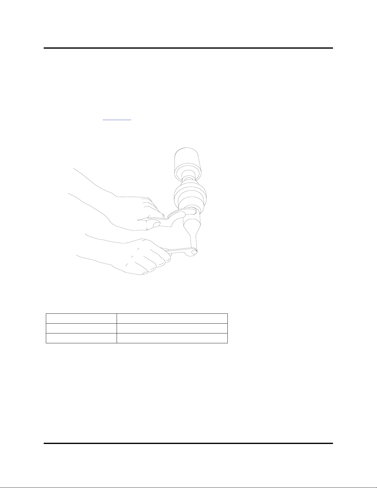
2000X aod Actuator Chapter 4: Installation and Setup
Instruction Manual Assemble the Acoustic Stack
4.8.5 Connecting Tip to Horn
1. Clean the mating surfaces of the horn and tip. Remove foreign matter from the threaded stud and hole.
2. Hand assemble the tip to the horn. Assemble dry. Do not use any silicone grease.
3. Use the spanner wrench and an open-end wrench (refer to Figure 4.19) and tighten to the Torque tip
specifications in Table 4.11
Figure 4.19 Connecting Tip to Horn
.
Table 4.11 Tip to Horn Torque Specifications
Tip Thread Torque
1/4 - 28 110 in.-lbs, 12.42 Nm.
3/8-24 180 in.-lbs, 20.33 Nm.
100-214-282 Rev. 07 4-35

Chapter 4: Installation and Setup
Stack Assembly
Carriage
Support
Washer
Screw
Main Support
Assembly
Hex Screw
Carriage Door
Contact
Term in al
Carriage
Stack Assembly
T-Handle
Wrench
Assemble the Acoustic Stack
4.8.6 Installing the Stack in the Actuator
20 kHz and 30kHz CA-30 Stacks
The ultrasonic stack must first be assembled. To install the stack:
1. Make sure that the system power is turned off by disconnecting the power plug.
2. Loosen the four door screws.
3. Pull the door straight off and set it aside.
4. Take the assembled ultrasonic stack and align the ring on the booster just above the support washer in
the carriage. Firmly push the stack into place, with the acorn nut on the top of the converter making contact with the contactor in the top of the carriage.
5. Reinstall the door assembly, and start the four door screws.
6. Align the horn by rotating it, if necessary. Torque the carriage door to 50 in.-lbs to secure the stack.
Figure 4.20 Installing a 20kHz Stack in a Branson Actuator
4-36 100-214-282 Rev. 07
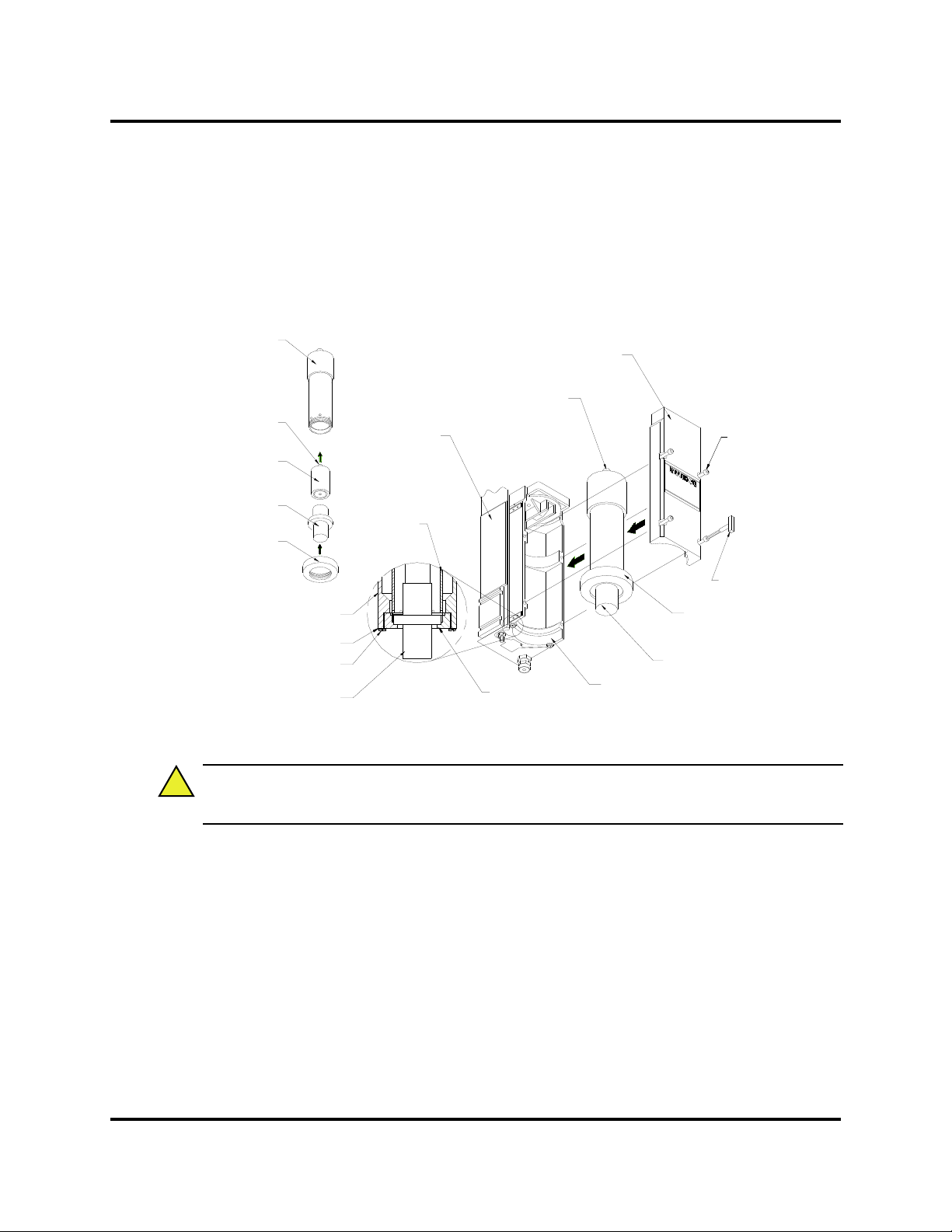
2000X aod Actuator Chapter 4: Installation and Setup
CAUTION
!
Converter
Carriage
Support Washer
Screw
Stack Assembly
Main Support
Assembly
Adapter Sleeve
T-Handle
Wrench
Stack Assembly
Carriage
Ring Nut
Ring Nut
Adapter
Sleeve
Contact Terminal
Booster
Adapter Sleeve
Adapter Sleeve
Contact Terminal
Carriage Door
Cap Screw
Ring Nut
(no Horn installed)
Instruction Manual Assemble the Acoustic Stack
40 kHz Stacks
1. Make sure that the system power is turned off by disconnecting the power plug.
2. Place the converter / booster in the sleeve.
3. Loosen the four carriage door screws.
Figure 4.21 Installing a 40kHz Stack in a Branson Actuator
4. Pull the door straight off and set it aside.
5. Take the assembled sleeve and align the ring nut on the booster just above the support washer in
6. Reinstall the door assembly, and start the four door screws.
7. Align the horn by rotating it, if necessary. Torque the carriage door to 20 in.-lbs to secure the stack.
100-214-282 Rev. 07 4-37
Do not attempt to hold the sleeve in a vise. It can be easily crushed or damaged.
the carriage. Firmly push the sleeve into place, with the acorn nut on the top of the converter making
contact with the contactor in the top of the carriage.

Chapter 4: Installation and Setup
CAUTION
!
9.00 in / 229mm
7.00 in / 178 mm
4.44 in / 113 mm
M = metric M10 hardware
10.50 in
287 mm
12.50 inch
317.5 mm
Optional
Guard
shown for
position only
Leveling Plate
mounting dimensions
Mounting the Fixture on the Branson Base
4.9 Mounting the Fixture on the Branson Base
(hardware and mounting holes)
The base provides mounting holes for your fixture. Mounting holes are also provided for the optional Branson leveling plate kit. The base is tapped for metric M10-1.5 hardware (indicated by an “M” on the base).
The mounting holes are arranged in three concentric bolt circles with the following dimensions.
The base is cast metal and the mounting holes can become stripped if the hardware is overtightened. Tighten your hardware only enough to prevent movement of your fixture.
Figure 4.22 Mounting Circles on Base
The optional guard, EDP 101-063-550, (sometimes required with very large horns) is shown for position
only. It extends several inches to either side of the base, and prevents the user from operating the welder and
pinching their fingers or hands between the base and the tooling.
4-38 100-214-282 Rev. 07

2000X aod Actuator Chapter 4: Installation and Setup
READY:TIME= 0.010
Preset 0
Adjust Weld>
Weld Results>
Select
Select
Weld
Setup
Select
Print
Main
Menu
Horn
Down
Display Control
Increase Decrease
Clear/
Delete
Delete
Go
Back/
Escape
100
80
60
40
20
0
Tes t
Reset
Power
-
+
7
8
9
0
321
456
Run
Instruction Manual Testing the Installation
4.10 Testing the Installation
1. Turn on the air supply connections with the air pressure regulator set at minimum values, and verify
that the system has air pressure.
2. Ensure there are no leaks in the air supply connections.
3. Turn on the power supply. The power supply will begins its normal self-check.
4. If the power supply displays an alarm message, find the alarm message definition, cause and correction in Chapter 7 of this manual.
5. Press the Tes t button.
6. If the power supply displays an alarm message at this point, find the alarm message definition in
the Maintenance section of Chapter 7 of the power supply manual. If there are no alarm messages
displayed, go on to the next step.
7. Fit a test part onto the fixture.
8. Press the Horn Down key and then press and hold the two start switches. The horn will descend
to the fixture on the base of the Actuator. This verifies specifically that the pneumatic system is
working.
9. Press the Horn Down key again. The horn will retract. The system should now be functional and
can be set up for your application.
In summary, if the power supply does not display an alarm message and the actuator descends and retracts
correctly, your ultrasonic welder is ready for operation.
Figure 4.23 Normal Front Panel Display After Power-Up
100-214-282 Rev. 07 4-39

Chapter 4: Installation and Setup
Still Need Help?
4.11 Still Need Help?
Branson is pleased that you chose our product and we are here for you! If you need parts or technical assistance with your 2000X-series system, call your local Branson representative or contact Branson customer
service by calling the appropriate department as indicated in Table 1.2:
Departments to Contact.
Branson Contacts, in Section 1.5.3:
4-40 100-214-282 Rev. 07

2000X aod Actuator Chapter 5: Technical Specifications
Instruction Manual Technical Specifications
Chapter 5: Technical Specifications
5.1 Technical Specifications - - - - - - - - - - - - - - - - - - - 5-1
5.1.1 Requirement Specifications - - - - - - - - - - - - - - - - - 5-1
5.1.2 Performance Specifications - - - - - - - - - - - - - - - - - 5-2
5.2 Physical Description - - - - - - - - - - - - - - - - - - - - - 5-3
5.2.1 Standard Items - - - - - - - - - - - - - - - - - - - - - - - 5-3
5.1 Technical Specifications
5.1.1 Requirement Specifications
The 2000X aod Actuator requires compressed air. The factory air source must be “clean (5
micron) and dry,” that is, does not include moisture or lubricants. The Actuator requires 70 psi
minimum pressure for operation and cooling, and can require up to 100 psig maximum, depending on the application. The following table lists environmental specifications for the ultrasonic
welder.
Table 5.1 Environmental Specifications
Environmental Concern Acceptable Range
Humidity Maximum 95% non-condensing
Operating Altitude Up to 6560 ft (2000 m)
Ambient Temperature +5°C to +50°C (+41°F to +122°F)
Storage/Shipping Temperature
All electrical input power connections are to the Power Supply.
-25°C/-13°F to +55°C/+131°F
(+70°C/+158°F for 24 hours)
100-214-282 Rev. 07 5-1

Chapter 5: Technical Specifications
Technical Specifications
5.1.2 Performance Specifications
The following tables detail some of the performance specifications associated with the 2000aod
Actuator.
Table 5.2 Max. welding force, dynamic trigger force, dynamic follow-through
Cylinder
Size
1.5" 130 lbs / 578 N 5-159 lbf / 22-707 N 5-159 lbf / 22-707 N 4" / 101.6 mm
2.0" 270 lbs / 1.2 kN 5-282 lbf / 22.1.25 kN 5-282 lbf / 22.1.25 kN 4" / 101.6 mm
2.5" 440 lbs / 1.96 kN 10-440 lbf / 44-1.96 kN 10-440 lbf / 44-1.96 kN 4" / 101.6 mm
3.0" 640 lbs / 2.84 kN 10-636 lbf / 44-2.83 kN 10-500 lbf / 44-2.22 kN 4" / 101.6 mm
Table 5.3 Maximum Traverse Speed
Max. clamp force
at 100 psig/690
kPa and 4"stroke
Dynamic triggering
range
Dynamic follow-
through range
Stroke length
Down and Return
Speed
7 inch/ 177.8 mm per sec. max at 3.5-inch / 88.9 mm stroke, 90
psi (all cylinder sizes)
Minimum Stroke: 1/8” / 3.2 mm
Maximum Stroke: 3-3/4” / 95.2 mm (for a 4" cylinder)
5-2 100-214-282 Rev. 07

2000X aod Actuator Chapter 5: Technical Specifications
Instruction Manual Physical Description
5.2 Physical Description
Refer to Chapter 4 for dimensional information.
5.2.1 Standard Items
Actuator Support
The actuator support is firmly clamped to the column. With the actuator support, you can adjust
the height of actuator housing above the fixture position. You can set the height as needed for
your application, or to facilitate servicing.
Actuator Base
Table 5.4 Description of Controls on Base
Name Description
Start Switches
Emergency Stop Button
Start Cable Connects base to START connector on Actuator.
Activate the operating cycle through the actuator to the
power supply when pressed simultaneously.
Interrupts the operating cycle (through the power supply)
and causes the carriage to retract. Twist to reset.
Slide Mechanism
The slide mechanism is based on eight sets of preloaded, permanently lubricated bearings, providing consistent, precise alignment of the horn, smooth linear motion, and long-term reliability.
Limit Switch, Function
The optical Upper Limit Switch (ULS) signals the control circuits in the power supply that the
carriage has returned to the top of its stroke (home) and is ready to start another operating cycle.
The power supply uses the ULS signal to perform various control functions, as in the following
examples:
• Indexing Control: In automated systems, the Linear Encoder generates an Actuator Clear
signal at a preset distance along the travel of the horn. This signal can be used to trigger a
safety interlock switch, controlling movement of the material handling equipment (indexing)
before the horn is fully retracted.
• Electronic Pretriggering: A 2000-series Power Supply can use the ULS signal to activate
ultrasonics before the horn contacts the workpiece. Pretriggering is used with large or difficult-to-start horns and in specialized applications.
100-214-282 Rev. 07 5-3

Chapter 5: Technical Specifications
CAUTION
!
NOTE
i
i
Physical Description
Mechanical Stop
The mechanical stop limits the downward travel of the horn. To prevent equipment damage,
adjust the stop so that the horn will not contact the fixture when no workpiece is in place. There
is an indicator on the right side showing the position of the stop block. It is not intended for use
in welding by distance.
Do not loosen the top hex-headed nut. Damage to the mechanical stop can result.
Turning clockwise will increase the stroke length; turning counter-clockwise will
shorten the stroke length. Adjustment is approximately 0.04-inch (1 mm) per rotation.
Pneumatic System
The pneumatic system is contained within the actuator and the remote pneumatics box. The system consists of:
1. a primary solenoid valve,
2. a cooling solenoid valve,
3. an air cylinder,
4. a pressure regulator,
5. and an air-pressure gauge.
6. down speed flow control valve
The horn’s rate of descent (downspeed) is adjusted at the front of the rp box using the Downspeed control knob. The rate of ascent is fixed. Refer to Figure 5.1 for a schematic of the pneumatic system.
5-4 100-214-282 Rev. 07

2000X aod Actuator Chapter 5: Technical Specifications
3
6
1
2
4
5
INPUT
EXHAUST
FLOW CONTROL VALVE
REGULATOR
COOLING
VALVE
CYLINDER
PRIMARY
MAC VALVE
TO
CARRIAGE
FILTER
Instruction Manual Physical Description
Figure 5.1 2000X Actuator Pneumatic System
100-214-282 Rev. 07 5-5

Chapter 5: Technical Specifications
Physical Description
S-Beam Load Cell and Dynamic Follow Through
The S-Beam Load Cell measures the force being applied to the part to trigger ultrasonics and
record the welding parameters. The S-Beam load cell assembly ensures that pressure is applied
to the part prior to the application of ultrasonic energy.
To maintain horn-to-part contact and force as the joint collapses, theS-Beam load cell assembly
provides dynamic follow-through. As the plastic melts, the S-Beam load cell assembly ensures
smooth transmission of ultrasonic energy into the part.
Linear Encoder
The encoder measures the distance the horn has travelled. Depending on the power supply settings, it can:
• Allow for distance welding
• Detect improper setup controls
• Monitor the quality of the weld
• Decrease cycle time by generating signal to initiate indexing of material handling equipment
before horn is fully retracted
5-6 100-214-282 Rev. 07

2000X aod Actuator Chapter 6: Operation
WARNING
!
Instruction Manual Actuator Controls
Chapter 6: Operation
6.1 Actuator Controls - - - - - - - - - - - - - - - - - - - - - - - 6-1
6.2 Initial Actuator Settings - - - - - - - - - - - - - - - - - - - - 6-2
6.2.1 Regulated Air Pressure and Air Pressure Gauge - - - - - - 6-2
6.2.2 Factory Air Source - - - - - - - - - - - - - - - - - - - - - 6-3
6.2.3 Downspeed Control - - - - - - - - - - - - - - - - - - - - 6-3
6.2.4 Actuator Alignment and Height (Horn travel) - - - - - - - - 6-4
6.2.5 Mechanical Stop - - - - - - - - - - - - - - - - - - - - - - 6-4
6.2.6 Emergency Stop - - - - - - - - - - - - - - - - - - - - - - 6-5
6.3 Operating the Actuator - - - - - - - - - - - - - - - - - - - - 6-5
6.1 Actuator Controls
This section describes how to operate a weld cycle using the 2000X aod Actuator. For more
detailed information on making and altering settings, refer to your 2000X-series Power Supply
manual.
When setting up and operating the Actuator, observe the following precautions:
Keep hands away from under the horn. Down force (pressure) and ultrasonic
vibrations can cause injury.
Plastic parts can vibrate within the audible frequency range when welded. If this
occurs, use hearing protectors to prevent possible injury. Do not allow the ultrasonically activated horn to touch a metal base or a metal fixture.
100-214-282 Rev. 07 6-1

Chapter 6: Operation
WARNING
!
CAUTION
!
Initial Actuator Settings
The 2000aod Actuator is controlled by the Power Supply. The Actuator sends operating cycle
data (such as velocity and force), status information, and alarm information to the Power Supply.
The Power Supply sends operating parameters to the Actuator, determining how and when weld
cycles are initiated and terminated. The Actuator passes distance, force, and pressure information continuously to the Power Supply while in Setup mode. Refer to your 2000X-series Power
Supply manual for tuning, testing, setup, and operating instructions.
When using larger horns, avoid situations where fingers could be pinched
between the horn and the fixture. Contact Branson for information on an optional
guard.
6.2 Initial Actuator Settings
The Actuator is controlled by the Power Supply, however there are several functions that are part
of the Actuator. These include:
• Factory Air Source
• Regulated Air Pressure and Air Pressure Gauge (located on the rp)
• Downspeed Control (located on the rp)
• Mechanical Stop
• Actuator Position and Height above fixture (Horn travel)
• Emergency Stop (on Base, and provided as a User I/O signal for automation)
Each of these will affect the operation of the Actuator.
6.2.1 Regulated Air Pressure and Air Pressure Gauge
When factory air is present, it is delivered to the regulator located in the rp box. The regulator
knob is a push-to-lock knob to prevent undesired changes in your air pressure settings.
When factory air is removed from the system, or the dump valve is activated, the
Actuator may “settle” to a lower position, since it is held up by the constant air
pressure. Be sure to keep your hands and fingers from under the Horn or other
pinch points, and use a block of wood or other soft material to block the Horn up
to prevent damage to the tooling.
6-2 100-214-282 Rev. 07

2000X aod Actuator Chapter 6: Operation
CAUTION
!
NOTE
i
i
NOTE
i
i
Instruction Manual Initial Actuator Settings
Initially, set the Regulator Knob to a counter-clockwise position, which is a low pressure setting.
In the event something is incorrectly connected, a low air pressure setting will reduce any sudden
movement. A typical initial setting is approximately 20-25 psi for a new or unproven setup.
Permanent damage to the system and possible injury can result if the Actuator is
supplied with factory air above the maximum gauge reading of 100 psig (690kPa).
Set the pressure regulator to zero before connecting or disconnecting the factory
air supply.
6.2.2 Factory Air Source
Factory air must be turned on, supplying the actuator’s air pressure regulator with air pressure.
If factory air is too low (below 35 psi maintained) the actuator will not weld or operate reliably.
Factory air is also used to provide cooling air to the converter.
Factory air input may affect weld results for applications requiring more weld pressure buildup.
Factory Air pressure must be greater than the maximum system requirements.
The compressed air system must have sufficient capacity to serve all of the systems connected to it. The use of an accumulator may be required to provide continuous air flow.
6.2.3 Downspeed Control
The Downspeed Control regulates the horn velocity. If the Downspeed control is closed, the
actuator will not extend
Be sure to set the down speed control to a slow setting, between 5 and 15, for an
initial setup. The downspeed control knob has a set-screw locking mechanism
that can be used, if desired.
100-214-282 Rev. 07 6-3

Chapter 6: Operation
Initial Actuator Settings
6.2.4 Actuator Alignment and Height (Horn travel)
The horn carriage will travel up and down on the actuator’s slides. The actuator can also be
adjusted up or down on the column. The distance between the fixture and horn should allow easy
and ready access and removal of your parts.
• Minimum stroke cannot be less than 1/8”.
• Maximum stroke cannot exceed 3-3/4” before part contact to allow for the operation of the
dynamic flow through mechanism.
Consistent weld results are best measured when the horn travel is more than 1/4 inch, because a
shorter distance can be affected by other components of the welding system and a suitable buildup of pressure on the parts.
6.2.5 Mechanical Stop
The Mechanical Stop affects the amount of downward travel the Actuator is allowed to have, up
to the full stroke length of the unit. The multi-turn knurled knob to the right of the Stack, on the
bottom of the Actuator, is the Mechanical Stop adjustment. The Mechanical Stop has an indicator on the right side of the Actuator, showing a scale of an arbitrary unit of measure.
The Mechanical Stop is designed to stop the Horn from contacting your Fixture in the event your
part is missing. It is not a precision measuring device, and it is usually not recommended that
this be used as a ‘collapse’ or other distance weld limiting device. The "missing part" function
can also be used to control critical horn to fixture distances.
Initially, set the mechanical stop to allow at least 1/4 inch of Horn travel, but any distance up to
the full stroke length is suitable.
To adjust the Mechanical Stop:
Step: Action:
1
2
3
6-4 100-214-282 Rev. 07
Activate the manual dump valve and manually lower the carriage until the
horn is just above the fixture.
If the horn does not reach the fixture and has not travelled 4 inches (100
mm), loosen the lock ring fully and turn the mechanical stop-adjusting knob
clockwise until the carriage reaches the desired position.
If the horn reaches the desired position before contacting the stop, turn the
adjusting knob counter-clockwise until the stop contacts the carriage.
Check the height of the horn and make any necessary adjustments to the
stop.

2000X aod Actuator Chapter 6: Operation
NOTE
i
i
Instruction Manual Operating the Actuator
When you have reached the setting you want, tighten the lock ring. The
4
lock ring will prevent the mechanical stop adjustment from vibrating loose
during operation.
5
6
Place a part in the fixture, reset the air pressure, and perform a test weld.
Check that full force develops between the horn and the part. If not, readjust the mechanical stop.
Due to Dynamic Follow Through, do not weld in the last 1/4" of stroke.
6.2.6 Emergency Stop
The Emergency Stop is a user control that will prevent the actuator from running, and will also
immediately terminate a weld cycle and cause the Horn to retract. It does not remove power from
the system. The controls can be configured to provide a beep sound when the emergency stop is
engaged. The front panel display of the power supply will indicate that the system is in emergency stop mode when it is. Twist the emergency stop button to reset the system.
6.3 Operating the Actuator
For detailed information about 2000X aod Actuator controls, refer to Section 2.4: Controls and
Indicators.
To operate the X aod actuator:
Step: Action:
If your application has been analyzed in the Branson Applications Laboratory, consult the
1
2
3
100-214-282 Rev. 07 6-5
Branson Lab Report for appropriate settings or check the 2000X distance Power Supply
manual.
Properly adjust the mechanical stop so that the horn does not make contact with your
fixture. (Refer to 6.2.5 ’Mechanical Stop’ on page4 for more information on this adjust-
ment.)
If the Actuator is mounted on a Base, make sure that the Emergency Stop button is not
pushed in.
If not using the Branson Base, verify that the Emergency Stop signal source is not in the
Emergency Stop mode.

Chapter 6: Operation
Operating the Actuator
Step: Action:
4
5
6
7
8
9
10
With a part in place, depress and hold both start switches simultaneously, or activate the
start mechanism.
The horn advances and contacts the part.
Force develops between the horn and the part, activating the load cell.
Ultrasonic vibrations are activated. The power bar graph on the power supply indicates
loading (usually in the 25% to 100% range). The start switches can now be released.
Ultrasonics stop and the horn continues to clamp the part for the hold time you selected.
After the completion of the hold cycle, the horn retracts automatically and you can
remove the part from the fixture.
Weld a few parts using the initial parameters and check for the desired properties.
If you do not obtain optimal results initially, based on the quality of the weld obtained and the
loading meter reading, you can alter settings to achieve satisfactory results. Change one setting
at a time until a weld is produced in minimum time with maximum strength.
6-6 100-214-282 Rev. 07

2000X aod Actuator Chapter 7: Maintenance
Instruction Manual Calibration
Chapter 7: Maintenance
7.1 Calibration - - - - - - - - - - - - - - - - - - - - - - - - - - 7-1
7.2 Periodic and Preventive Maintenance - - - - - - - - - - - - 7-1
7.2.1 Periodically Clean the Equipment - - - - - - - - - - - - - - 7-1
7.2.2 Recondition the Stack (converter, booster, and horn) - - - - 7-2
7.2.3 Routine Component Replacement - - - - - - - - - - - - - 7-4
7.3 Parts Lists- - - - - - - - - - - - - - - - - - - - - - - - - - - 7-5
7.1 Calibration
This product does not require scheduled calibration. However, if you are operating under
requirements that mandate periodic calibration, for example, the FDA’s Good Manufacturing
Practices, contact your Branson representative for additional information.
7.2 Periodic and Preventive Maintenance
The following preventive measures will help ensure long term operation of your Branson 2000
Series Actuators.
7.2.1 Periodically Clean the Equipment
Periodically disconnect the unit from power, remove the cover and vacuum out any accumulated
dust and debris. Remove material adhering to the circuit boards, cooling intake vents and
exhaust ports. Periodically disconnect the airline from the air supply, open the air filter and clean
the element and bowl with mild soap and water. External covers may be cleaned with a damp
sponge or cloth using a solution of mild soap and water. Do not allow cleaning solution to enter
the unit. Exposed steel surfaces, such as handles, hardware and the main column may require a
very light film of oil, such as WD-40, to prevent rust in areas of high humidity.
100-214-282 Rev. 07 7-1

Chapter 7: Maintenance
NOTE
i
i
CAUTION
!
NOTE
i
i
Periodic and Preventive Maintenance
7.2.2 Recondition the Stack (converter, booster, and horn)
Stack components function with greatest efficiency when the mating interface surfaces are in
proper condition. For 20kHz and 30kHz products, a Branson Mylar washer should be installed
between the horn and the booster, and booster and converter. Replace the washer if torn or perforated. We recommend that stacks using Mylar washers be inspected every three months.
Stacks used with silicone grease, as with certain 20 kHz installations and with all 40 kHz products, should be periodically reconditioned to eliminate fretting corrosion. We recommend that a
stack using silicone grease be inspected every two weeks for corrosion. The inspection interval
can then be adjusted longer or shorter as required, when experience is gained for specific stacks.
See the Branson instruction manuals for correct stack interface reconditioning procedures.
The operating efficiency of the equipment will be greatly affected if the mating
interfaces of the converter, booster, and horn are not flat, make poor contact with
each other, or become corroded. A poor contact condition wastes power and
makes tuning difficult. It may also affect the noise level and damage the converter.
To recondition the interfaces:
1. Remove the stack from the actuator.
2. Disassemble the converter, booster, and horn stack. Observe the following rules:
In the event that you must disassemble a Stack, always use the correct spanner wrench and a suitable soft-faced vise to remove a horn or booster, and reverse the procedures described earlier in
this Section.
NEVER attempt to remove a horn or booster by holding the converter housing or
booster clamp ring in a vise.
Use a soft-jawed vise (brass or aluminum) to remove square or rectangular horns,
or horns otherwise unremovable, by reversing the procedure detailed in Section
4.8 Assemble the Acoustic Stack, beginning on page 4-32.
3. Wipe the interfaces with a clean cloth or paper towel.
4. Examine all interfaces. If any interface is corroded or shows a dark, hard deposit, it should
be reconditioned.
5. If the interfaces appear to be in good condition, go to step 13.
6. If necessary, remove the coupling studs.
7-2 100-214-282 Rev. 07

2000X aod Actuator Chapter 7: Maintenance
NOTE
i
i
NOTE
i
i
CAUTION
!
Instruction Manual Periodic and Preventive Maintenance
7. Tape a clean sheet of #400 grit (or finer) emery cloth to a clean, smooth flat surface. A piece
of glass is suitable.
8. Hold the part to be conditioned at its lower end and carefully stroke it in one direction across
the emery cloth. Do not press down. the weight of the component provides enough pressure.
9. Perform a second stroke. Rotate the part 1/3 around and stroke it twice across the cloth.
Use no more than two strokes in one position. Use the same number of strokes
at each location.
10. Turn the part the remaining 1/3 and repeat.
11. Re-examine the interface and repeat steps 8, 9, and 10 until the surface appears clean and
smooth. This should not take more than 2 or 3 complete rotations of the part being reconditioned.
12. Clean the threaded hole, using a clean cloth or paper towel.
13. Replace the stud with a new one if removed. Torque the 3/8-24 studs to 290 inch pounds
(32.77 Nm). Torque 1/2-20 studs to 450 inch pounds (50.84 Nm).Torque M8x1-1/4 studs to
70 inch pounds (7.9 Nm).
The use of a Branson torque wrench or the equivalent is recommended. P/N 101063-617 for 20kHz systems and 101-063-618 for 40kHz systems.
Failure to follow torque specifications may cause the stud to loosen or break, and
the system to overload. The use of a Branson torque wrench or equivalent is
required.
14. Reassemble the stack and install it in the actuator, using the procedures in Section 4.8
Assemble the Acoustic Stack, beginning on page 4-32 of this manual.
100-214-282 Rev. 07 7-3

Chapter 7: Maintenance
Periodic and Preventive Maintenance
7.2.3 Routine Component Replacement
The lifetime of certain parts is based on the number of cycles the unit has completed, or on hours
of operation. Table 7.1
when components should be replaced. Ambient operating temperature also affects lifetime.
Higher temperatures reduce the number of cycles and hours before replacement is suggested.
The charts below are for equipment operating at a temperature of 72 to 75
The lifetime of system pneumatic components is influenced by the quality of the compressed air
provided. All Branson systems require clean, dry, (normal) factory compressed air. When oil or
moisture is present in the compressed air, the lifetime of the pneumatic components will be
reduced. This table lists pneumatic parts with an average factory compressed air condition.
Table 7.1 Component Replacements Based on Cycles Run
lists the average number of hours or cycles one should use in determining
o
F (22 - 24o C).
At 10 Million Cycles
At 20 Million Cycles Base Palm Buttons
At 40 Million Cycles
Air Cylinder
Hydraulic snubber
Solenoid Valves
Pressure Regulator
Air Filter
Cooling Valve
S-Beam Load Cell Assembly
Encoder Assembly
Linear Bearing (2" stroke or greater)
For Reference Purposes:
1) A system operating at 60 welds per minute, 8 hours per day, 5 days per week, 50 weeks per
year completes approximately 7.2 million cycles in 2000 hours.
2) The same system at 24 hours per day, 5 days per week, in 50 weeks completes 21.6 million
cycles in 6000 hours.
3) 24 hours per day, 365 days per year produces 31.5 million cycles in 8760 hours.
Please note that parts replaced during preventive maintenance constitute normal wear and tear.
They are not covered by warranty.
7-4 100-214-282 Rev. 07

2000X aod Actuator Chapter 7: Maintenance
Instruction Manual Parts Lists
7.3 Parts Lists
The following tables lists the available Accessories (Table 7.2) and Parts (Table 7.3) for the
2000X aod Actuator:
Table 7.2 Accessories List for aod Actuator
Description EDP Number
aod Actuator with 1.5-inch diameter cylinder 101-134-276
aod Actuator with 2.0-inch diameter cylinder 101-134-277
aod Actuator with 2.5-inch diameter cylinder 101-134-278
aod Actuator with 3.0-inch diameter cylinder 101-134-280
aodl Actuator with 2.5-inch diameter cylinder 101-134-279
aodl Actuator with 3.0-inch diameter cylinder 101-134-281
Kit Base Guard (for large horns) 101-063-550
Remote Pneumatics Box (rp) 101-246-1350
Remote Pneumatics Low Force Box for 1.5" and 2.0"(rplf) 101-246-1351
AE/AO Dump Valve 100-246-952
Inch Leveling Plate 101-063-358
Metric Ball Bolt (adapts 2000X base to leveling plates) 100-298-085
Metric Leveling Plate 101-063-444
CJ20 Acorn (in actuator) 101-135-059
30kHz Retaining Ring (for use with CJ30) 100-246-1072
CA30 Acorn 101-134-114
4TJ Acorn (in actuator) 101-135-041
40 kHz Adapter Sleeve Assy (same as 900) 100-246-612
Stand-Base, 1/4 col, support 100-246-1314
Stand-Hub, 1/4 col, support 100-246-1344
Base, ergo - 4” metric, black 100-246-1037
Hub, 2000X for 4” column 101-063-583
Support 4” black 100-246-1035
Column 4’, 40’ x 1/4” wall 100-028-021
100-214-282 Rev. 07 7-5

Chapter 7: Maintenance
Parts Lists
Table 7.2 Accessories List for aod Actuator (Continued)
Column 4’, 4” x 1/4” wall (option) 100-028-017
Column 4’, 4” x 1/2” wall (option) 100-028-011
Column 6’, 4” x 1/2” wall (option) 100-028-012
Sleeve, 1/4” wall column 100-094-159
Sleeve, 1/2” wall column 100-094-102
900 Series Boosters (1/2-20 Input; 1/2-20 Output
Black (Ti), Ratio 1:2.5 101-149-059
Silver (Ti), Ratio 1:2 101-149-058
Gold (Ti), Ratio 1:1.5 101-149-057
Description EDP Number
Green (Ti), Ratio 1:1 101-149-056
Purple (Ti), Ratio 1:0.6 101-149-060
Silver (Al), Ratio 1:2 101-149-053
Gold (Al), Ratio 1:1.5 101-149-052
Green (Al), Ratio 1:1 101-149-051
Purple (Al), Ratio 1:0.6 101-149-055
Solid Mount Boosters - 20kHz - 1/2-20 Input, 1/2-20 Output
Black (Ti), Ratio 1:2.5 101-149-099
Silver (Ti), Ratio 2:1 101-149-098
Gold (Ti), Ratio 1:1.5 101-149-097
Green (Ti), Ratio 1:1 101-149-096
Purple (Ti), Ratio 1:0.6 101-149-095
Boosters - 30kHz (for use with CA-30 converter)
Black (Ti), Ratio 1:2.5 101-149-120
Silver (Ti), Ratio 1:2.0 101-149-121
Gold (Ti), Ratio 1:1.5 101-149-122
Green (Ti), Ratio 1:1 101-149-123
Purple (Ti), Ratio 1:0.6 101-149-124
7-6 100-214-282 Rev. 07
 Loading...