

Page 1

www.brainproducts.com
V-Amp & ImpBox
Operating Instructions
Page 2

V-Amp | Operating Instructions
Copy right
Any trademarks mentioned in this document are the protected property of their rightful owners.
The reproduction, distribution and utilization of this document as well as the communication of its contents to
others without express authorization is prohibited. Offenders will be held liable for the payment of damages. All
rights reserved in the event of the grant of a patent, utility model or design. Subject to change without notice.
For the latest version of this document, please visit www.brainproducts.com or contact your local distributor.
Published by Brain Products GmbH
Zeppelinstrasse 7
82205 Gilching
Germany
Published on* May 2, 2016 Document version 007
*Valid until publication of a new version of this document.
© 2016 Brain Products GmbH
Phone: +49 (0) 8105 733 84 - 0
Fax: +49 (0) 8105 733 84 - 505
Web: www.brainproducts.com
Page 3

Contents 3
Contents
About these operating instructions................................................................................. 4
About the product .......................................................................................................... 7
Safety ..........................................................................................................................10
Chapter 1 Overview ................................................................................................ 14
1.1 V-Amp at a glance ................................................................................... 14
1.2 ImpBox at a glance.................................................................................. 16
Chapter 2 Installation............................................................................................. 18
2.1 Installing the driver ................................................................................. 18
2.2 Confirm the installation........................................................................... 19
Chapter 3 Operation ............................................................................................... 21
3.1 Connecting electrodes ............................................................................ 21
3.2 Operating modes .................................................................................... 23
3.3 Trigger ports and cables (digital ports)..................................................... 27
Chapter 4 Active electrodes .................................................................................... 29
4.1 How the active electrodes work ............................................................... 29
4.2 Preparing the actiCAP for acquisition ....................................................... 29
4.3 Minimizing the impedances of the actiCAP electrodes.............................. 30
Chapter 5 Troubleshooting ..................................................................................... 32
5.1 Driver cannot be installed (Windows® XP and Vista)................................ 32
5.2 Error messages ....................................................................................... 34
5.3 Replacing faulty electrodes ..................................................................... 35
Chapter 6 Maintenance, care and disposal.............................................................. 37
6.1 Maintenance........................................................................................... 37
6.2 Care........................................................................................................ 37
6.3 Disposal ................................................................................................. 38
Appendix A Technical data ........................................................................................ 39
Appendix B Pin-out ................................................................................................... 44
Appendix C Ordering Codes....................................................................................... 48
Page 4

About these operating instructions 4
About these operating instructions
These operating instructions describe how to use V-Amp and how it is integrated into a measurement setup. The operating instructions form an integral part of V-Amp. They must be precisely adhered to in order to ensure that V-Amp is used as intended and operated correctly to guarantee the
concomitant safety of test subjects, users and third parties. Make sure that these operating instructions are always available to the users.
No part of this document may be reproduced or distributed in any form without the express written
permission of Brain Products. The operator may print this document to make it available for the users of the product. Please keep this document and Application Suite DVD in a safe place.
Make sure that you have the most recent operating instructions for your product or product revision.
Please visit our website to download a more recent version: http://www.brainproducts.com
loads.php.
/down-
Target group of this document
This document is intended for users in the psychological and neurophysiological research area as
well as physicians and medical experts with experience in performing physiological data acquisition. Staff must also know how to work safely and reliably with the permitted amplifier and the associated recording software.
Structure of this document
This document is divided into the following chapters:
Chapter 1 introduces the V-Amp and ImpBox with their supplied accessories and also describes
the basic functions.
Chapter 2 describes how to install the V-Amp drivers on your PC.
Chapter 3 describes how the V-Amp and ImpBox are incorporated in a measurement setup and
covers the basic software configuration.
Chapter 4 describes the basic characteristics of the active electrodes.
Page 5

About these operating instructions 5
!
NEW
Chapter 5 contains information on common sources of error and how to rectify these. You should
first check whether any of these sources of error could be responsible for any problems you are
experiencing before contacting our technical support team.
Chapter 6 contains information on care and maintenance and on the correct way of disposing of
old units.
Conventions in this document
Typographical conventions
Bold indicates items on the user interface (menus, buttons, switches, connectors,
options) and is used for emphases in the text
Italic indicates titles of dialog boxes/tabs, file locations and is used to indicate
product names
Underscore
Monospaced indicates text or characters to be entered at the keyboard
indicates cross-references and web addresses
Symbols
Caution: This symbol indicates that incorrect use of the product(s) may result in a
personal injury to the test subject, the user and/or a third-party. Failure to observe
the information in this document constitutes incorrect use.
Notice: This symbol indicates that the incorrect use of the product(s) may bring
about a risk of damage to property.
Note or Tip: This symbol draws your attention to important information relating to the
current topic and to recommendations on how to use the product(s).
Cross-reference: This symbol indicates a reference to a related chapter, section or
document.
New: This symbol indicates changes or new content at this point.
Page 6

About these operating instructions 6
Revision History
Page . . . .Status . . . . . Subject
7 modified Product identification (CE marking)
46 modified Pin-out of 40-way connector for actiCAP
Support and reporting errors
We would ask you to report without delay any error you find in this document, any fault on the products or any malfunction that you observe when using this product. To do so, please contact your local dealer, who will also assist you in general questions about the product.
Page 7

About the product 7
NEW
About the product
The V-Amp manages a variety of signals like EEG, ERP, EOG, ECG, EMG as well as the full range of
evoked potentials. Sensors for peripheral signals like GSR, blood flow, temperature also interface
with the V-Amp auxiliary ports.
It has up to 16 data channels for passive and active electrodes. The EEG-signals acquired with the
electrodes and sensors are amplified, digitized and transferred to a computer via USB for display
and storage.
The V-Amp is a versatile amplifier for a wide range of applications (e.g. biofeedback experiments,
teaching courses).
Product identification
Product designation: Brain Products V-Amp 8
Brain Products V-Amp 16
ImpBox
Manufacturer: Brain Products GmbH
Zeppelinstraße 7
82205 Gilching
Phone: +49 (0) 8105 733 84 - 0
Fax: +49 (0) 8105 733 84 - 505
Website: http://www.brainproducts.com
Electrical safety according
to IEC 60601:
CE marking The Brain Products GmbH confirms the electromagnetic compatibil-
Scope of delivery: V-Amp:
Protection class II
ity (EMC) of this product according to the Directive 2014/30/EU of
the European Parliament and of the Council of 26 February 2014 on
the approximation of the laws of the Member States relating to
electromagnetic compatibility.
- V-Amp Trigger cable
- V-Amp USB cable
- Application Suite DVD
ImpBox:
- 2 Mignon AA batteries
- 1 battery charger
Page 8

About the product 8
Combination with other products
Brain Products permits the user to combine the V-Amp with the following product families:
Product Manufacturer
actiCAP active EEG electrode system
Brain Products GmbH
(incl. splitter box and ControlBox)
EP-PreAmp (only with V-Amp 16) Brain Products GmbH
Acceleration Sensor
GSR Sensor
Respiration Belt
Brain Products GmbH
Brain Products GmbH
Brain Products GmbH
Photo sensor Brain Products GmbH*
StimTrak Brain Products GmbH
actiCAP Xpress Brain Products GmbH
TriggerBox & TriggerBox Extension Brain Products GmbH
Passive Ag/AgCl EEG electrodes/caps
EasyCap GmbH
*
(e.g. Multitrode/Brain Cap)
Electrode gel or paste
Blood Pulse Sensor
Temperature Sensor
EasyCap GmbH
Becker Meditec
Becker Meditec
*
*
*
*
*
*
BrainVision Recorder Brain Products GmbH
Computer The computer to which you connect the amplifier
must fulfill the IEC 60950-1 or EN 60950-1.
* Other manufacturers on request
Brain Products permits the user to combine the ImpBox with the following product families:
Product Manufacturer
actiCAP active EEG electrode system Brain Products GmbH
EP-PreAmp Brain Products GmbH
Beside this general statement about permitted product combinations, the user must check, if all
stipulations of each product are fulfilled for the specific combination and purpose of application
(i.e. intended use and correct use).
Page 9
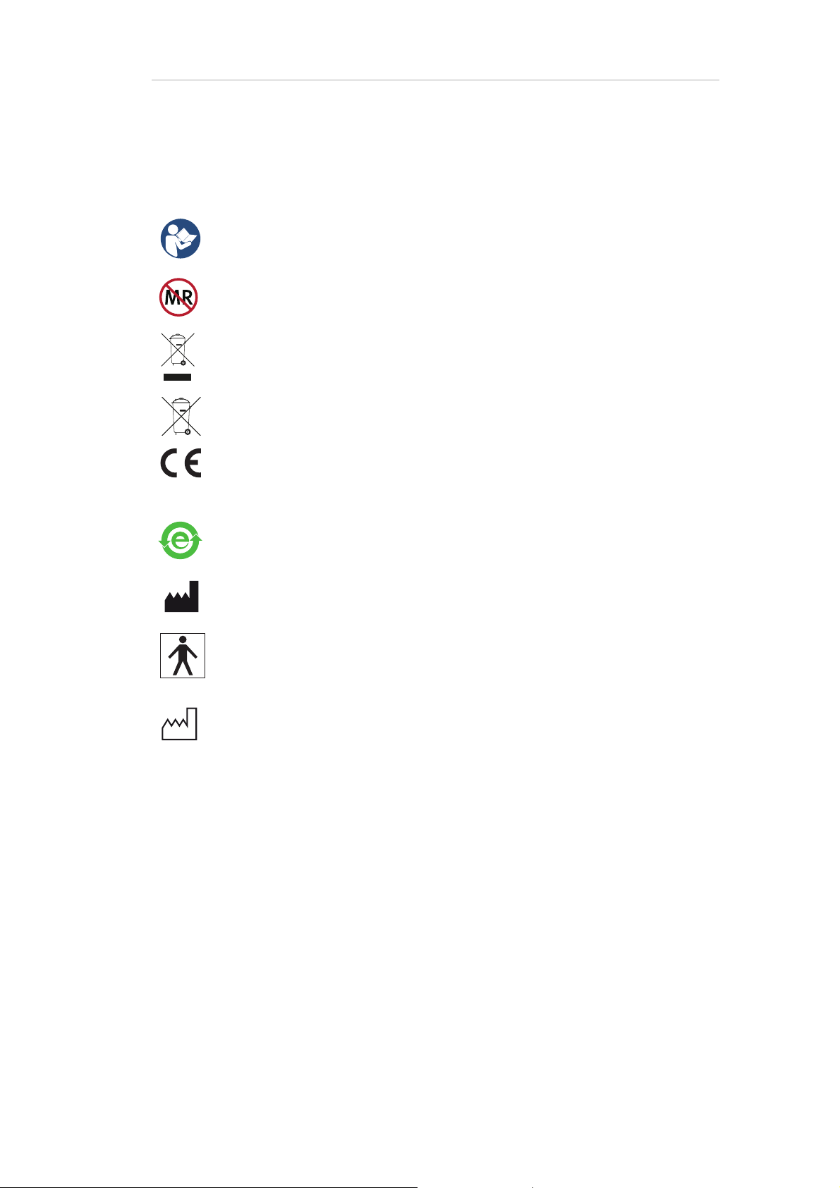
Markings on the products
Observe the operating instructions.
MR unsafe: Products with this symbol are not safe for use in an MR environment.
These symbols indicates that defective products must not be disposed of with
household waste. Dispose of in accordance with national regulations or return
the product and its accessories to the manufacturer.
The Brain Products GmbH confirms the electromagnetic compatibility (EMC) of
this product according to the Directive 2014/30/EU of the European Parliament
and of the Council of 26 February 2014 on the approximation of the laws of the
Member States relating to electromagnetic compatibility.
About the product 9
This symbol confirms compliance with the environmental requirements for electronic products (only applies to China).
Next to this symbol the name and address of the manufacturer is specified.
Patient applied part of type BF. Although marking confirms a BF applied part
according to 60601 (2nd ed.), this product is not a medical device.
Not for use in conjunction with a defibrillator!
Next to this symbol the manufacturing date is specified.
Page 10

Safety 10
Safety
Please read the following safety information carefully since it helps to prevent personal injury and
damage to property. It is assumed that you have the required specialist knowledge in handling the
product and accessories.
Brain Products will not accept any liability for loss or damage resulting from a failure to follow these
operating instructions and, in particular, the safety instructions.
Intended use
V-Amp
V-Amp is intended to be used for amplifying and digitizing neuro-/electrophysiological signals
(e.g. EEG, EMG, ECG, EOG).
V-Amp is not a medical device. Use of V-Amp for diagnosis, therapy, monitoring of vital physio-
logical processes (such as cardiovascular functions etc.) or other medical purposes is expressly
forbidden.
ImpBox
The ImpBox is intended to be used for generating signals for the purpose of displaying impedance values.
ImpBox is not a medical device. Use of the ImpBox for diagnosis, therapy, monitoring of vital
physiological processes (such as cardiovascular functions etc.) or other medical purposes is expressly forbidden.
Correct use (V-Amp and ImpBox)
The V-Amp and/or ImpBox (in the following: V-Amp/ImpBox) are permitted to be used by users in
the psychological and neurophysiological research area as well as physicians and medical experts.
Page 11

Safety 11
The V-Amp/ImpBox is not permitted to be used by
unqualified persons (e.g. laymen),
persons who cannot read (e.g. due to visual impairment) or understand (e.g. due to a lack of lan-
guage skills) the operating instructions.
The V-Amp/ImpBox can be used to record neuro-/electrophysiological signals from healthy and sick
adults, children and animals.
The use of V-Amp/ImpBox for medical purposes is not permitted.
The V-Amp/ImpBox is permitted to be used in the following environments: Research institutes or
other non-medical environments (e.g. at home) as well as hospitals, clinics or other medical environments, provided that all the other stipulations regarding the correct use are met and that the V-
Amp/ImpBox is used in accordance with its intended use.
The V-Amp/ImpBox is not permitted to be used in the following environments:
MR scanner environment,
vicinity of explosive gases, as may be the case in operating theaters, for example,
oxygen enriched atmospheres,
underwater (e.g. sea, swimming pool, bath tub) or in environments which significant amounts
of water could enter the V-Amp/ImpBox (e.g. under shower, under water-tap)
The user is solely liable for any risks to test subjects associated with the investigation, if the products are not used in accordance with the correct use.
General precautions
Never use force to connect or disconnect the connectors.
Never disconnect cables by pulling on the cables. Always disconnect cables by pulling on the
plug itself.
Do not drop.
Do not kink cables.
The connectors on the products are intended for electrodes, electrode caps, sensors and trig-
gers. Never insert probes, metal pins or any other items into these connectors.
Heat, direct sunlight (UV beams), humidity, foreign material may impair the service life of the
amplifier and accessories (see also Appendix A
Use the IEC 60601-1-1 standard to combine V-Amp with other products, such as computers, pe-
ripherals, triggers sources, etcetera.
This product is not suitable for use in an MR environment.
).
Page 12

Safety 12
!
Caution
Not to be connected to a subject undergoing electro surgery or defibrillation.
Take care in arranging the electrode and sensor cables to avoid risk of entangle-
ment or strangulation.
Auxiliary probes or probe sets must comply with the electrical safety according to
IEC 60601. If used two probes with different functions and electrical connection
to the subject (for example GSR and BIP2AUX) or one probe with a set of functions
then a double or reinforced galvanic isolation between the function parts must be
used.
Notice
Only use the supplied cables. On no account use any longer cables that you may
already have.
Always fasten the fixation screws of the USB cable.
Explosion Hazard: Do not use in the environment of explosive gases (e.g. flamma-
ble anesthetic mixture with air) or Nitrous Oxide, and oxygen-enriched atmospheres.
Special Care for Cleaning!
No liquids must ingress the V-Amp, ImpBox and other products, such as the actiCAP splitter box.
Always dry the electrodes in a way, that no water can enter the connectors or actiCAP splitter box!
Page 13

Safety 13
Recording Quality
Do not use the products within 3 meters of an operating cellular phone, similar radio transmitting
or other powerful radio interference producing sources such as radio thermal treatment equipment,
x-ray machines, or equipment that produces electrical sparks. Otherwise the EEG recording might
contain noise/artifacts.
The data recording and the quality of the recorded data lies within the responsibility of the user. For
any queries about data recording and improving the quality, please contact the technical support
([email protected]
).
Page 14
Chapter 1 Overview
1.1 V-Amp at a glance
Scope of delivery
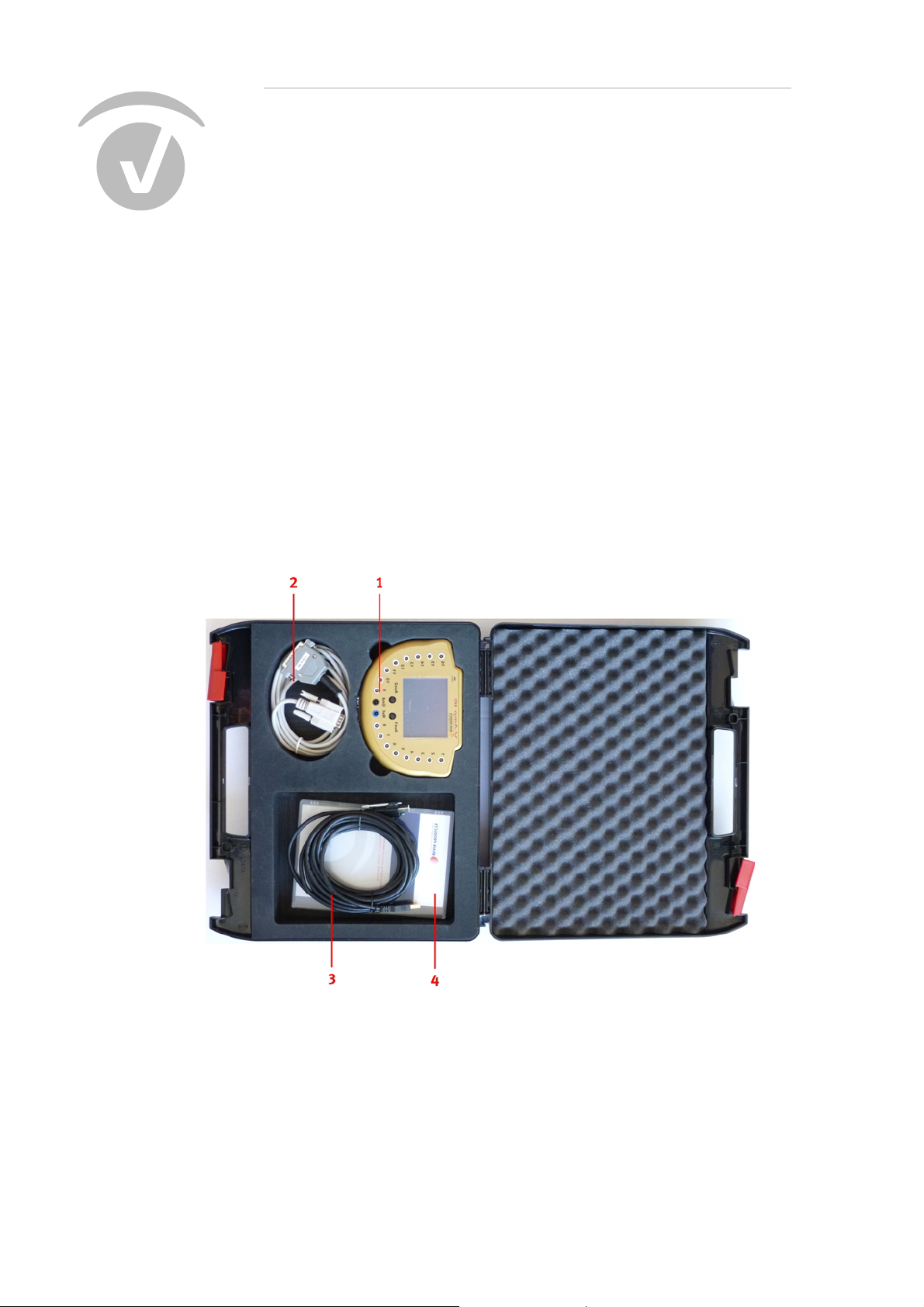
V-Amp is available as 8 or 16-channel version. The components listed below are included in the
scope of delivery.
14
Upon receipt of the delivery, make sure that the product or package does not show any signs of damage, or that the delivery is incomplete:
1 V-Amp 16 (depicted) or V-Amp 8
2 Trigger cable (9/25 pin male)
3 USB cable, Type A/B
4 Application Suite DVD
Page 15
Overview
Chapter 1 Overview 15
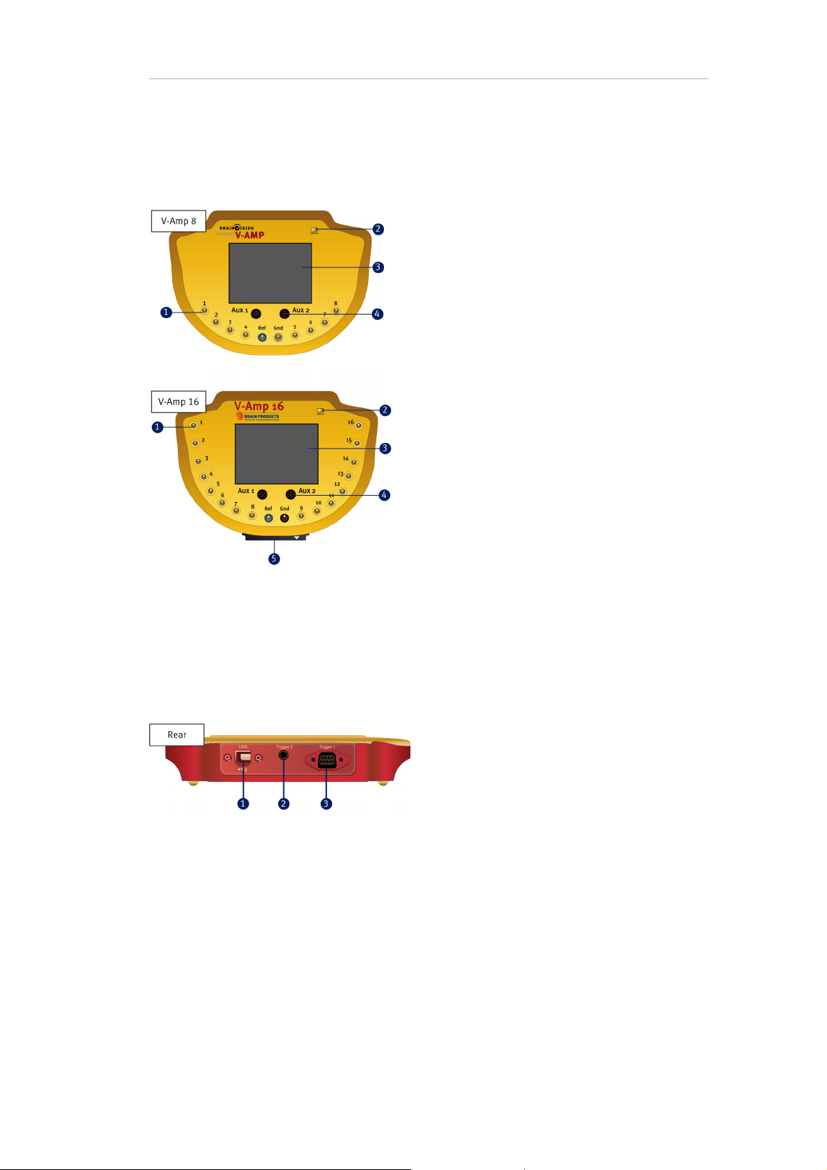
1 8 / 16 touch-proof jacks for passive data electrodes, 2 touch-proof jacks for REF and GND
2 Status LED
3 LCD screen
4 AUX connectors for additional sensors
5 40 pin connector for active electrodes (only for V-Amp 16)
1 USB port for power supply and data interface
2 Trigger 2 (jack plug)
3 Trigger 1 (9 pin female)
Page 16
Chapter 1 Overview 16
1.2 ImpBox at a glance
Upon receipt of the ImpBox, make sure that the product or package does not show any signs of damage, or that the delivery is incomplete.
Scope of delivery
ImpBox
2 x rechargeable Mignon AA batteries (NiMH)
Battery charger
Overview
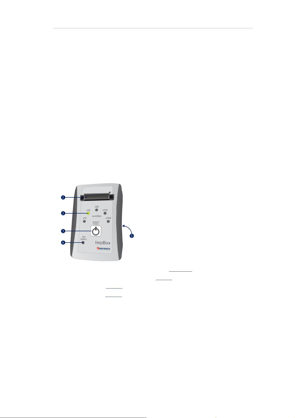
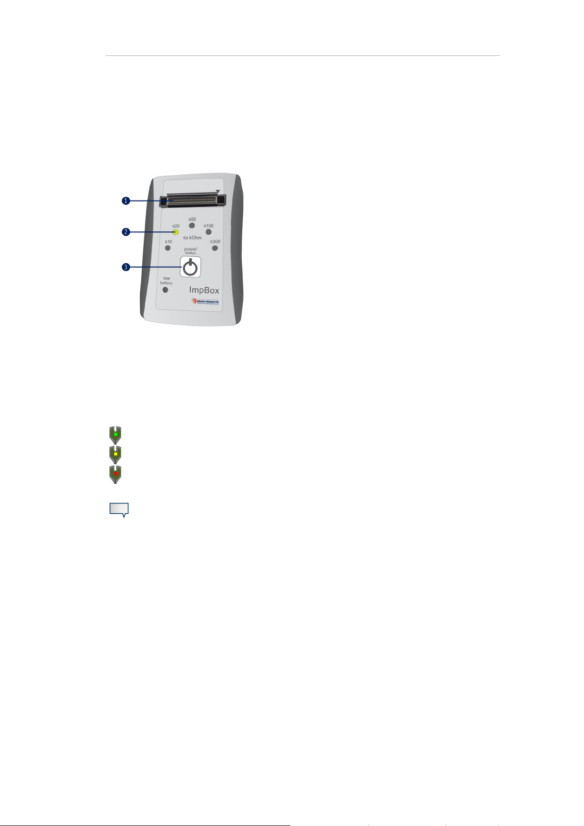
1 40 way connector for actiCAP splitter box (pin out see Appendix B)
2 LED, indicating the selected impedance range (page 23
3 power/switch button (page 17
4 low battery indicator (page 17
5 Rear: battery tray
)
)
f)
Functions
The ImpBox is used to determine the impedances for actiCAP active electrodes and can also be used
for the EP-PreAmpʼs passive electrodes.
Page 17

Chapter 1 Overview 17
Active electrodes have their own impedance converters, which allow working with higher impedance values. When using active electrodes it is sufficient to measure the impedance in ranges,
which is the reason why the ImpBox performs the impedance routine only in ranges instead of single
values. The available ranges are 10 kOhm, 20 kOhm, 50 kOhm, 100 kOhm, 300 kOhm. LEDs
in the active electrodes (or EP-PreAmp modules) will indicate, if the impedances are within the selected range or not (see also Section 3.2.1
Details on the actiCAP active electrode system or the EP-PreAmp are available in the
corresponding operating instructions. You can download these instructions from the
manual section of our website: http://www.brainproducts.com/downloads.php.
).
Power/switch button
The power/switch button has three different functions:
1 On: Press once.
2 Select a range: Press repeatedly until LED indicates impedance range (from low to high).
3 Off: Press and hold for 3 seconds.
Low battery LED
The ImpBox is powe red by t wo rech argeab le Mign on AA ba tterie s (supp lied). If the ir char ge b ecomes
insufficient, a red battery low LED illuminates. In this case you must replace or recharge the batteries.
Note
The batteries must be sufficiently charge in order to achieve reliable results.
Batteries
To change the batteries, slide open the battery tray on the rear side of the ImpBox. The orientation
of the battery positive and negative terminals are marked in the tray. Only use batteries of the supplied type (Mignon AA, NiMH, rechargeable). See also Appendix A
.
Page 18
Chapter 2 Installation
Before you can use the V-Amp amplifier for recording EEG-data you must install the V-Amp driver on
your computer.
2.1 Installing the driver
18
The complete installation comprises the following steps:
1 Install BrainVision Recorder.
The drivers for V-Amp will be installed with the software. Do not remove the Application Suite
DVD during the installation procedure.
To manually install the driver, please refer to Chapter 5
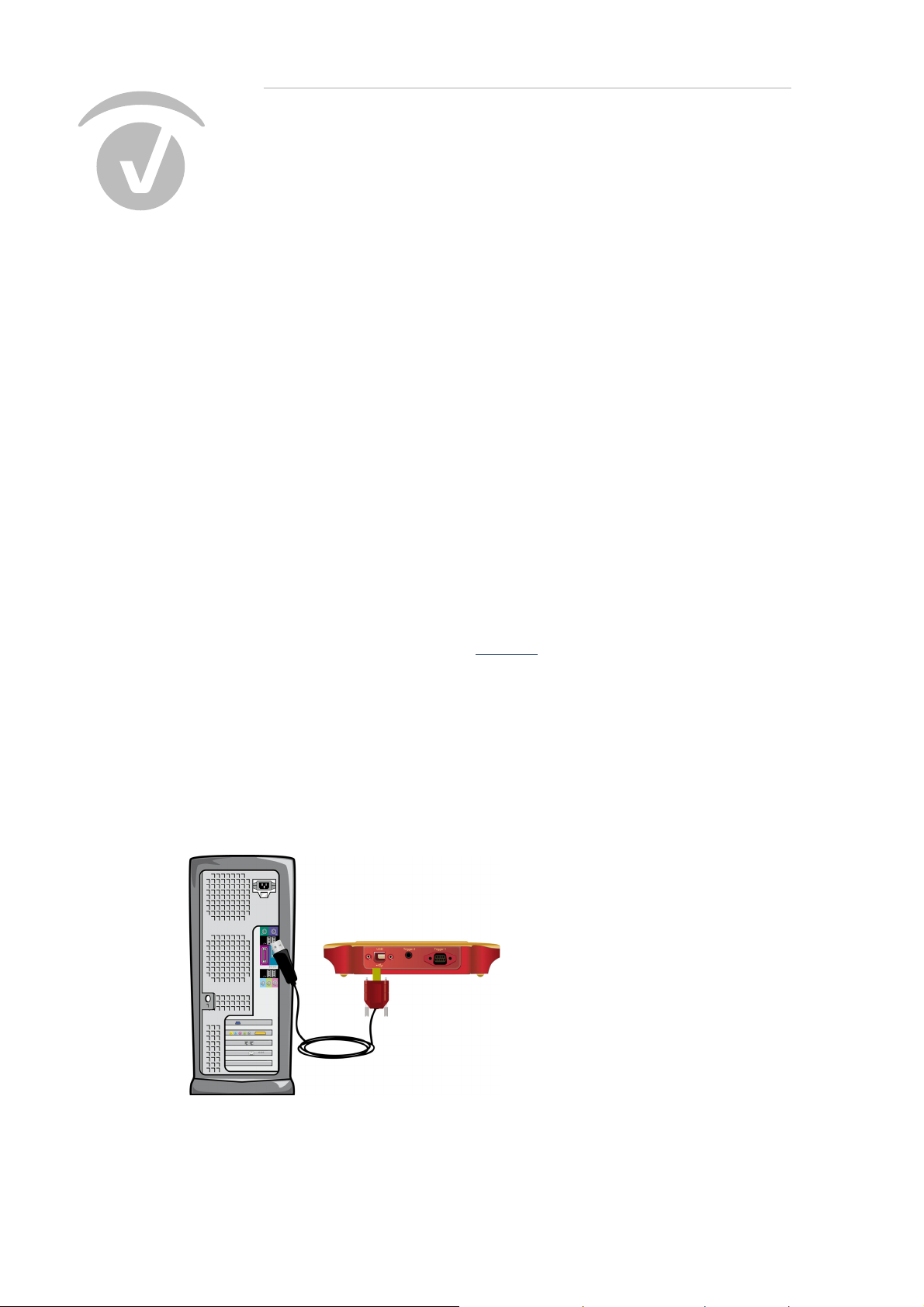
2 Connect V-Amp to the computer with the supplied USB cable.
Note: The computer to which you connect the amplifier must fulfill the IEC 60950-1 or EN 60950-
1.
The driver will be initialized. Every time you connect V-Amp to another USB port the drivers will
be initialized again.
Do not use USB hubs (e.g. on computer screens, keyboards etc). This can cause an instable
working environment.
.
Figure 2-1. Connect the USB cable
Page 19
3 Connect the dongle to the computer.
4 Start BrainVision Recorder and select the V-Amp/FirstAmp amplifier.
2.2 Confirm the installation
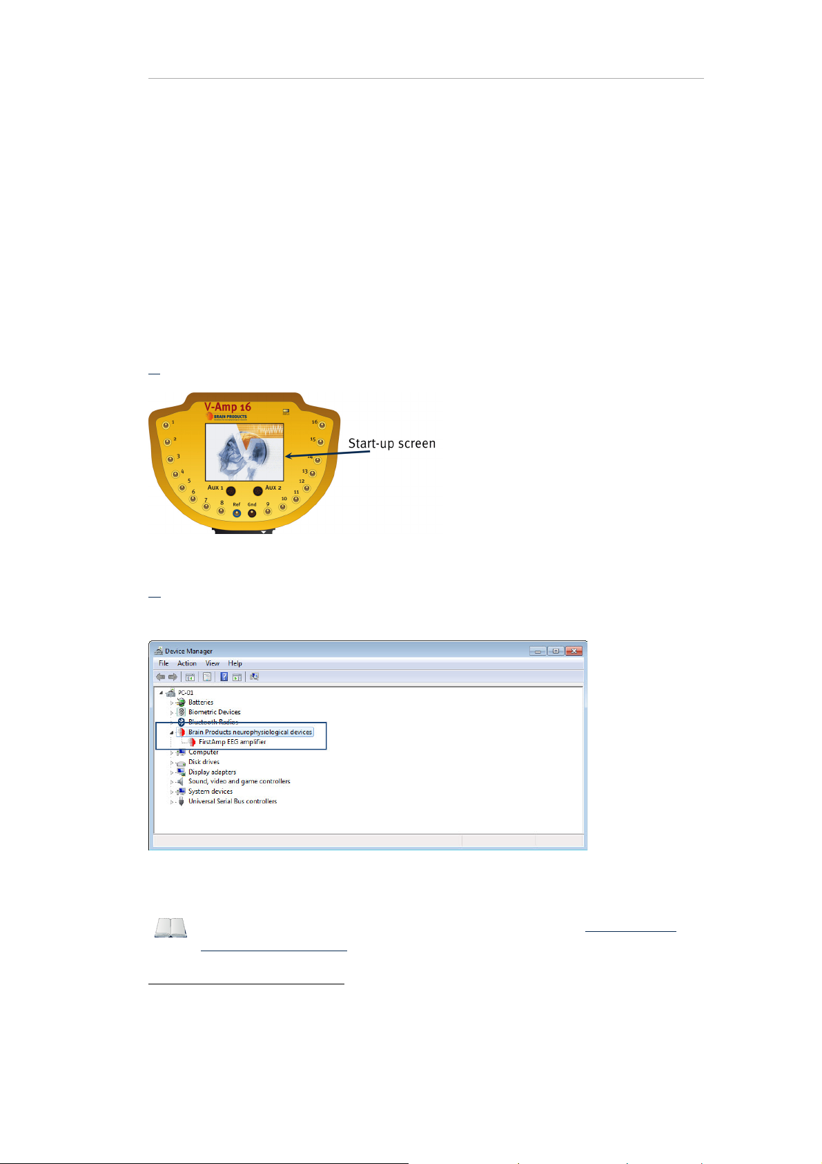
There are two ways to confirm the correct installation of V-Amp.
A)
When you connect V-Amp to the computer, the start-up screen appears.
Chapter 2 Installation 19
Figure 2-2. Confirm installation 1: start-up screen
Click on Start > Control Panel > Device Manager1. V-Amp should appear in the list of installed de-
B)
vices.
Figure 2-3. Confirm installation 2: Device Manager
For additional installation instructions please visit our website at www.brainprod-
ucts.com/downloads.php (set-up poster "How to Set-Up the V-Amp System").
1. You can also open the Device Manager by putting in the following location in a Windows Explorer address bar: Con-
trol Panel\All Control Panel Items\Device Manager
Page 20

Chapter 2 Installation 2021
Page 21
Chapter 3 Operation
3.1 Connecting electrodes
3.1.1 Passive electrodes
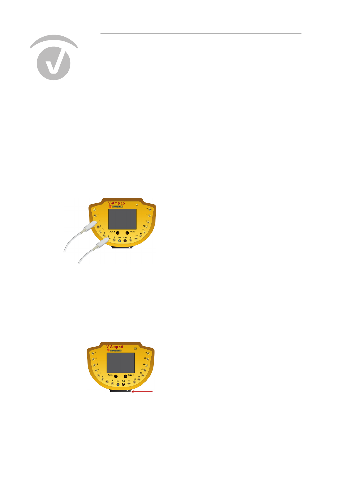
V-Amp has 8 or 16 touch-proof connectors for passive EEG-electrodes and connectors for the reference (blue) and ground (black) electrode. The connectors are located on the top.
Figure 3-1. Connectors for passive electrodes
3.1.2 Active electrodes
The V-Amp 16 models have a 40 way connector for active electrodes on the front. It carries the 16
EEG channels, the REF and GND channel as well as the power supply for the electrodes.
Figure 3-2. Connector for active electrodes
Page 22
Chapter 3 Operation 22
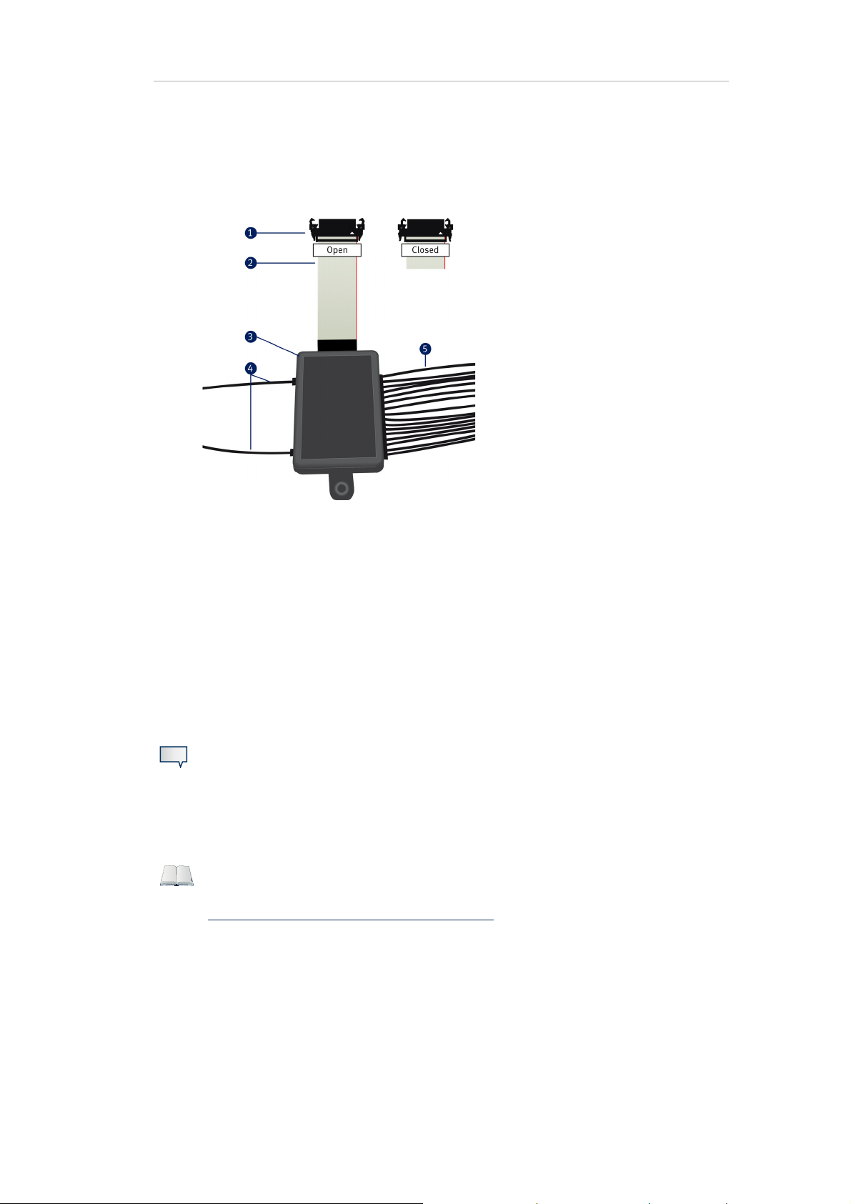
When you connect the splitter box to V-Amp, make sure that the clamps on the flat-ribbon cable are
fully engaged.
Figure 3-3. actiCAP splitter box for V-Amp
1 40-way connector
2 Flat-ribbon cable
3 Splitter box
4 Reference and ground electrodes
5 Data electrodes
To unplug the connector, press both clamps at the same time and carefully pull the connector from
the plug.
Note
Never connect passive and active electrodes at the same time! This may result in a
data loss.
For details about the actiCAP active electrodes, please refer to the actiCAP Operating
Instructions. You can download the latest version of this manual from our website:
http://www.brainproducts.com/downloads.php.
Page 23

Chapter 3 Operation 23
3.2 Operating modes
The V-Amp has three operating modes:
impedance measurement (page 23)
monitoring (page 25)
test signal (page 25)
Switching between these modes is performed in Recorder.
3.2.1 Impedance measurement
Depending on the electrode type, the electrode impedances are determined by different methods.
For passive electrodes, V-Amp has its own impedance routine and for active electrodes, the ImpBox
is used.
Passive electrodes
To measure the impedance of passive electrodes, do the following:
1 Prepare the electrodes on the test subject, e.g. by using abrasive paste and conductive gel.
2 Make the connections (electrodes to V-Amp and V-Amp to computer).
3 Start the Impedance Mode in Recorder.
4 Lower the impedances (if necessary)
First confirm that the impedance values of the REF and GND electrodes are in the 1-10 kOhm
range.
Then lower the impedances of the EEG electrodes.
During the impedance routine, the exact impedance values are displayed in Recorder and
also on the V-Amp LCD display.
5 When finished click on or to end the Impedance Mode.
The impedance values will be stored together with the EEG data. If you close Recorder before
starting to record the EEG signals, the impedance values will be lost.
Active electrodes
Use the ImpBox to measure the impedances of active electrodes.
To conduct the impedance measurement with the ImpBox do the following:
Page 24
Chapter 3 Operation 24
Connect the actiCAP splitter box to the 40 pin connector of the ImpBox (1).
Turn the ImpBox on by pressing the power/switch button (3).
Select a impedance range (levels) by repeatedly pressing the power/switch button (3). The se-
lected value will be displayed by the corresponding LED (2).
Figure 3-4. ImpBox - Overview
For active electrodes it is useful to start with a high impedance range and gradually select the next
lower range until you have reached a satisfying result.
Whether the selected value is reached, is indicated by the LEDs on the electrodes. The colors correspond to different value ranges:
Green: Impedance value lies within selected value range.
Yellow: Impedance value above selected range, but less than 150% of the range.
Red: Impedance value more than 150% of selected level.
Notes
Switch off the ImpBox before you disconnect the electrodes.
V-Amp does not have an impedance routine for active electrodes. If you try to mea-
sure the impedances with V-Amp instead of the ImpBox, you will get unrealistic
impedances of 0 kOhm for all electrodes.
Page 25

Figure 3-5. Example of wrong impedance
More information about handling the actiCAP active electrodes, please refer to
Chapter 4
.
Chapter 3 Operation 25
3.2.2 Monitoring
The monitoring mode is started by clicking on the button. Please note, that the EEG data and impedance values will only be stored when you click on the recording button .
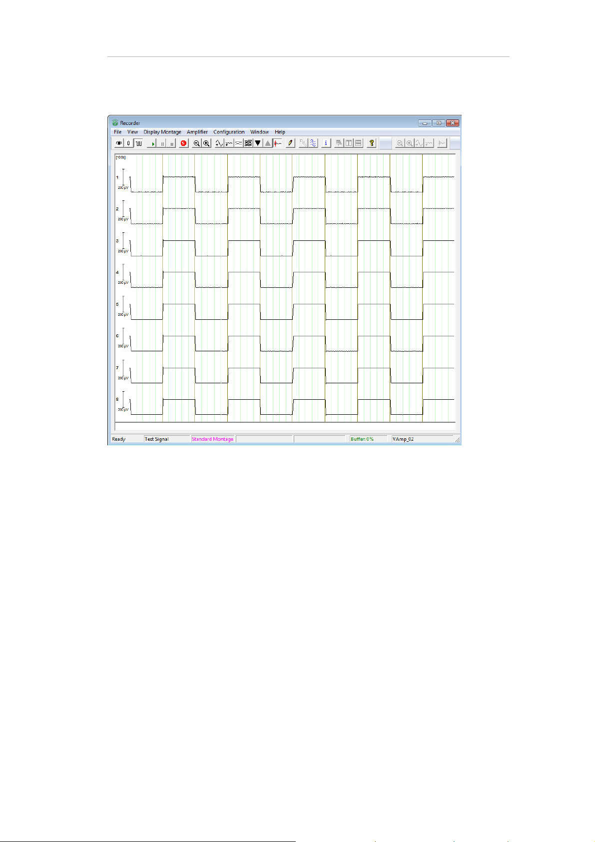
3.2.3 Test signal
If you are in doubt of the functional state of your V-Amp you can perform a test of the physical channels (excluding the AUX channels). When you start the test mode, Recorder shows a square wave for
all EEG channels.
Note
No electrodes must be connected during the test mode!
Page 26
Chapter 3 Operation 26
Figure 3-6. Example of a test signal
The square signal in the figure above contains noise. This is caused by an external power source
with a 50 Hz mains hum. For your project you should remove any interference source before you acquire the EEG data, in order to obtain a high-quality EEG signal.
Page 27
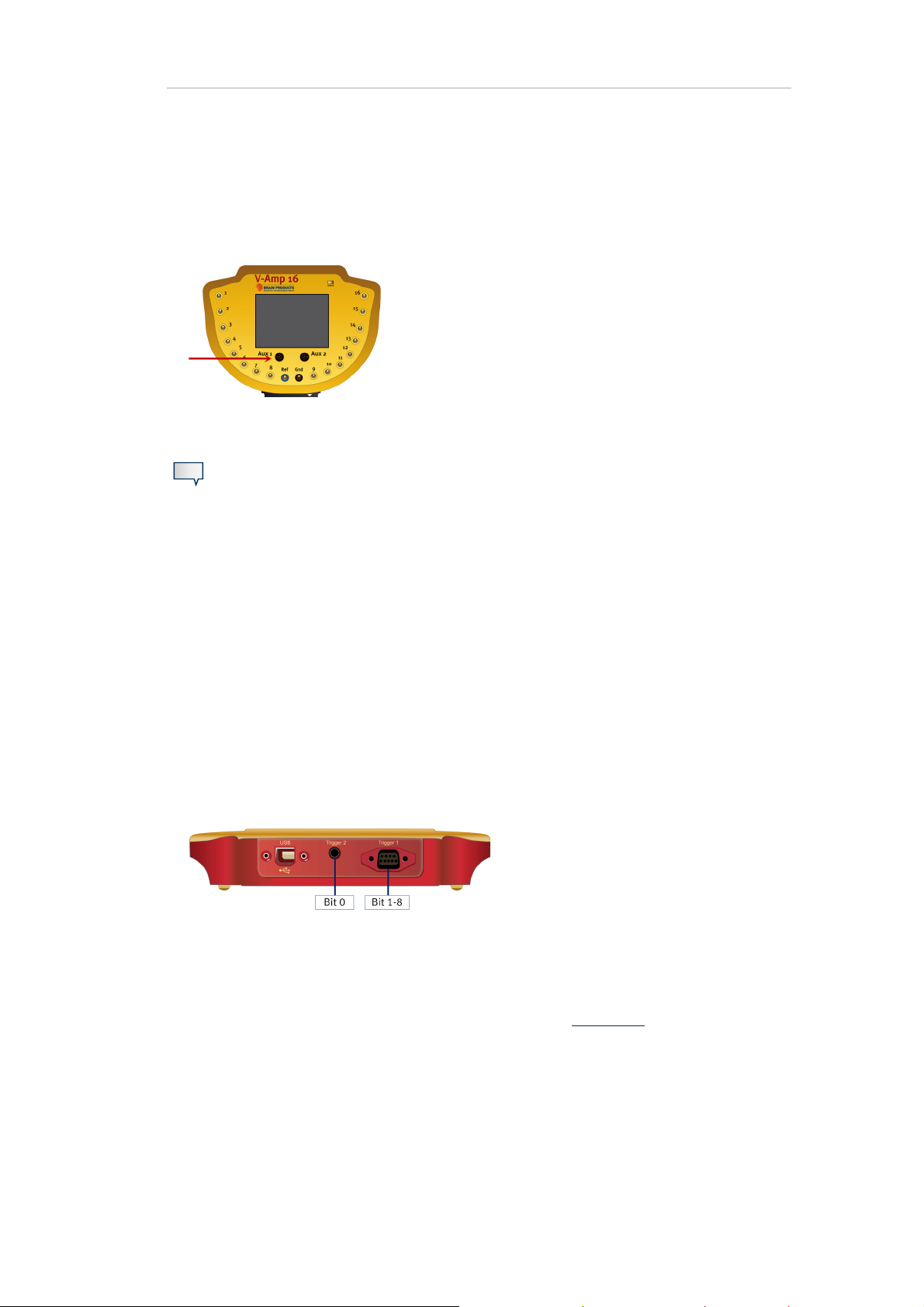
3.2.4 Auxiliary
V-Amp has two AUX inputs for sensors.
Figure 3-7. Location of AUX connectors
Note
The inputs AUX 1 and AUX 2have a common ground. Please make sure that sensors
with different functionalities are galvanically isolated from each other. The connected
sensors must comply with the electrical safety according to IEC 60601.
Chapter 3 Operation 27
3.3 Trigger ports and cables (digital ports)
The trigger ports on the V-Amp are used for recording events that are synchronous with the EEG,
such as stimuli or test subject responses. V-Amp has two trigger ports located on the rear:
Trigger 1: 9-pin D-Sub, Bits 1-8
Trigger 2: jack plug, Bit 0.
Figure 3-8. Location of trigger connectors and mapping of Bits 0-8
The cable of Trigger 1 port is supplied as standard. It has a 9-pin and 25-pin male D-Sub connector.
The cable for Trigger 2 port is optionally available and it has a stereo jack on the one end and a BNC
jack on the other end. For ordering these cables, please refer to Appendix B
.
Page 28

Chapter 3 Operation 28
You make the digital port settings in Recorder. Go to Amplifier > Digital Port Settings...
Note
A suitable ratio between the length of the trigger signal and the sampling rate is required to ensure that the TTL trigger signals are recorded without errors. You can select the appropriate sampling rate in the workspace.
Table 3-1
contains the recommended minimum trigger signal length for each sampling rate.
Sampling rate Minimum length of trigger signal
100 Hz 25.0 ms
250 Hz 10.0 ms
500 Hz 5.0 ms
1,000 Hz 2.5 ms
2,000 Hz 2.5 ms
5,000 Hz 0.5 ms
10,000 Hz 0.5 ms
20,000 Hz 0.5 ms
Table 3-1. Recommended minimum length for trigger signals
If the sampling rate is not suitable for the trigger length, trigger information can be lost. Therefore,
select a sampling rate matching the trigger length, in order not to loose any information.
For the pin-out of the connectors, please refer to Appendix B.
For more information on trigger settings please refer to the BrainVision Recorder User
Manual or to the user manual of your stimulus presentation software.
Page 29

Chapter 4 Active electrodes
4.1 How the active electrodes work
The actiCAP electrodes possess high-quality Ag/AgCl pellets as well as "active" circuits that are integrated in the electrodes (impedance converters). These make it possible to perform recording at
high impedances (e.g. 25 kOhm).
Alongside the integrated impedance converter, the electrodes also possess special electronic components which enable the ImpBox to measure the impedances between the electrode and scalp.
29
The LEDs which are integrated in the electrode housing indicate the impedance range of the current
electrode impedance by means of different colors (red, green, yellow).
4.2 Preparing the actiCAP for acquisition
The actiCAP electrode set consists of a splitter box with 16 numbered electrodes (+ REF and GND)
and a cap with numbered holders. The numbers enable you to assign the electrodes to the corresponding holders quickly. The cap also has two holders for the GND and REF electrodes that are
marked with GND and REF.
Perform the following steps:
1 Insert the electrodes in the actiCAP holders.
2 In BrainVision Recorder, you can import the electrode position file (*.BVEF) that is supplied with
the actiCAP or manually assign the physical channels to the electrode positions.
3 Place the cap on the test subject.
4 Fill the electrodes with gel (see Section 4.3
5 Perform the impedance measurement.
).
You can also use the electrodes to acquire EOGs, EMGs or ECGs. When doing so, use the supplied
actiCAP holders:
1 Insert the electrode in the holder.
2 Use an adhesive ring to apply the electrode to the required part of the body.
3 Fill the electrode with gel.
Page 30

Figure 4-1. EOG electrode
Chapter 4 Active electrodes 30
4.3 Minimizing the impedances of the actiCAP electrodes
To minimize the impedance values, connect the actiCAP splitter box to the ImpBox and turn on the
ImpBox. The LEDs of the electrodes now light up in red. Select the desired impedance range (e.g.
50 kOhm)
First minimize the impedances of the ground and reference electrode and only then minimize the
impedances of the EEG electrodes.
Proceed as follows:
1 Carefully push the blunt needle of the syringe through the electrode aperture as far as the scalp.
2 Gently roughen the scalp by means of careful circular movements of the needle. This increases
the contact area between the electrode gel and scalp.
3 Use the syringe to apply a small amount of gel (0.2 to 0.3 ml) directly to the scalp.
4 Then fill the remaining space in the electrode with gel, by slowly removing the syringe from the
electrode.
In this way, you will easily achieve the impedance of 25 to 35 kOhm.
When the impedance value changes, the electrode LEDs change from red to yellow or green depending on the ranges you have set (see also Section 3.2.1
).
Page 31

Chapter 4 Active electrodes 31
Figure 4-2. Filling the electrodes with gel
Using this procedure and with a little practice, you should be able to prepare 16 channels plus REF
and GND in about five minutes.
The impedances improve with time: First of all, fill all the electrodes with gel as described above.
Once you have prepared all the electrodes accordingly, perform a visual check of the impedances.
Make sure that the GND and REF electrodes are in range.
If the impedance in one or more electrodes has not been sufficiently minimized (LED lit yellow or
red), use the blunt needle in the nozzle to push through the electrode aperture again and roughen
the scalp a little more by means of circular movements. If necessary, use a little more gel.
Page 32
Chapter 5 Troubleshooting
5.1 Driver cannot be installed (Windows® XP and Vista)
If you are using Windows® XP or Vista, the driver might not install automatically. Therefore, when
you connect V-Amp to your Windows® XP or Vista computer for the first time, a wizard for new hardware might open. If this is the case on your system, then do the following:
5.1.1 Windows® XP
32
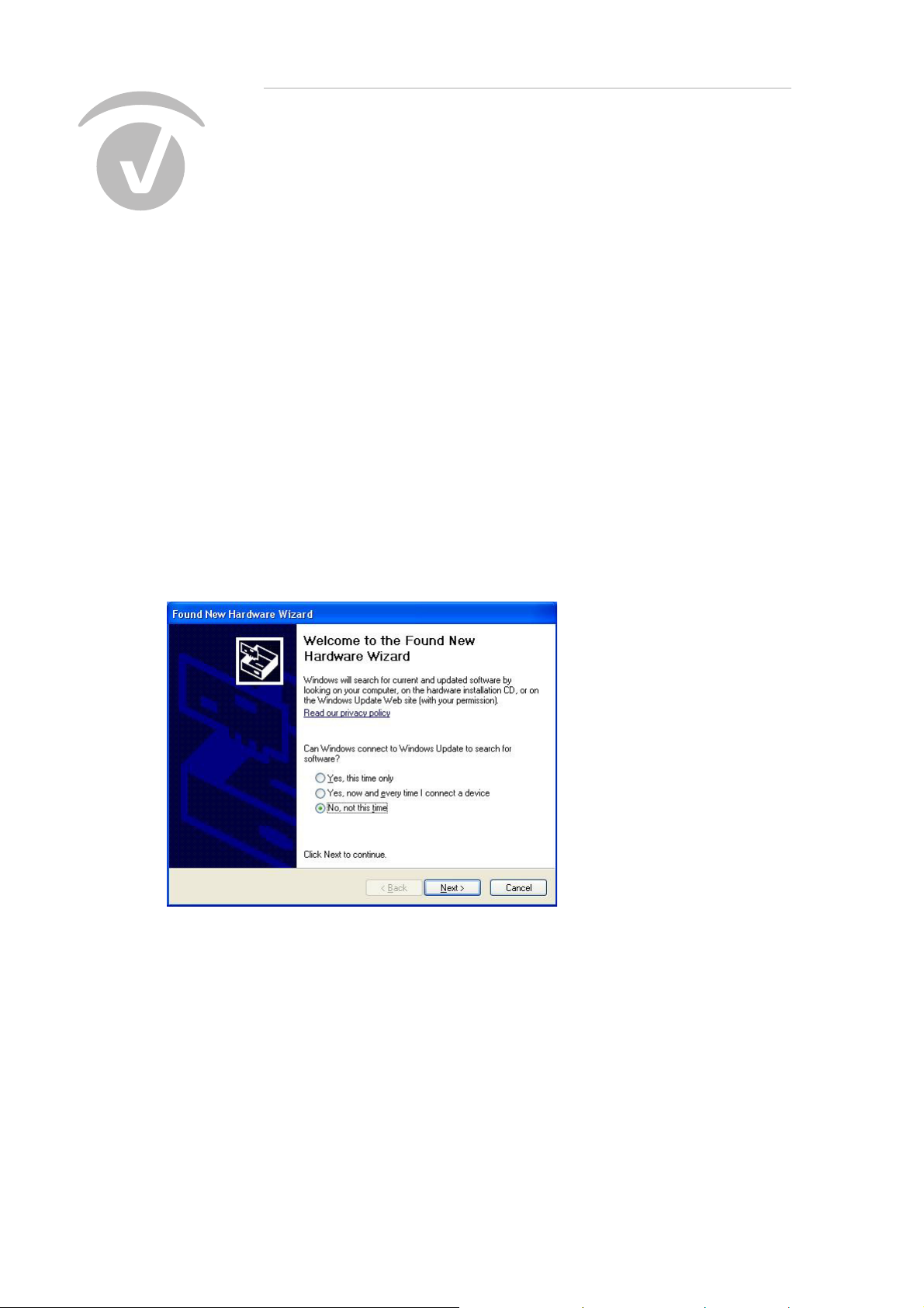
When prompted to connect to Windows® update, select No, not this time and click on Next.
Figure 5-1. Windows® XP, Wizard for new hardware (1)
Then insert the Application Suite DVD.
Select Install the software automatically (Recommended) and click on Next. This installs the V-
Amp USB driver. In some cases this prompt appears a second time. If so, repeat the previous
steps.
Page 33
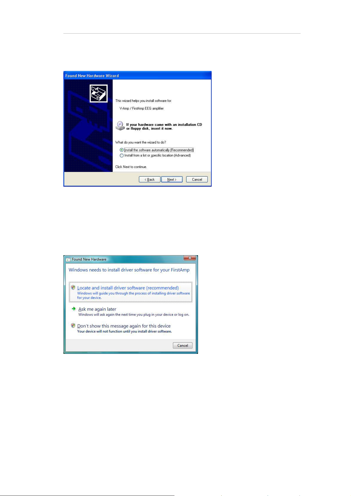
Figure 5-2. Windows® XP, Wizard for new hardware (2)
Chapter 5 Troubleshooting 33
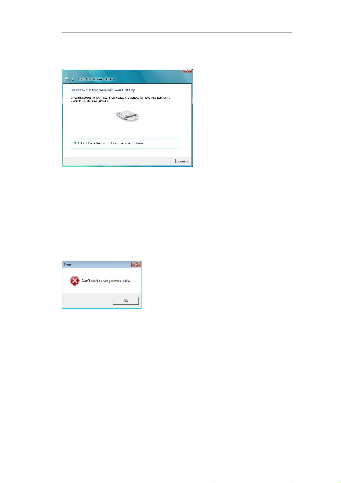
5.1.2 Windows® Vista
Connect V-Amp to your computer. The hardware installation wizard.
Figure 5-3. Windows® Vista, Wizard for new hardware (1)
Click on Locate and install driver software (recommended). The following dialog appears:
Page 34
Chapter 5 Troubleshooting 34
Figure 5-4. Windows® Vista, Wizard for new hardware (2)
Insert the Application Suite DVD. If the driver was not installed automatically, then you can lo-
cate it on the DVD.
5.2 Error messages
Figure 5-5. Warning message ‘Can’t start serving device data’
This error message in BrainVision Recorder can have the following cause: While V-Amp is connected
to your PC, your PC switches into sleep mode. When you re-activate the PC, V-Amp will not show the
start-up screen and BrainVision Recorder will display this error message if you access one of the
three modes (Monitor, Impedance Check, or Test Signal).
To resolve this issue:
Disconnect and re-connect the USB cable of V-Amp.
Change the power saving settings of your PC so that your PC will never switch into sleep mode.
(For details, please refer to the BrainVision Recorder User Manual.)
Page 35
Chapter 5 Troubleshooting 35
5.3 Replacing faulty electrodes
Proceed as follows to replace a faulty electrode:
1 Before replacing the electrode, disconnect the splitter box from the amplifier.
2 Remove the screw in the center of the cover.
3 Remove the cover.
4 Remove the metal bar on the side of the faulty electrode, by loosening the two small screws.
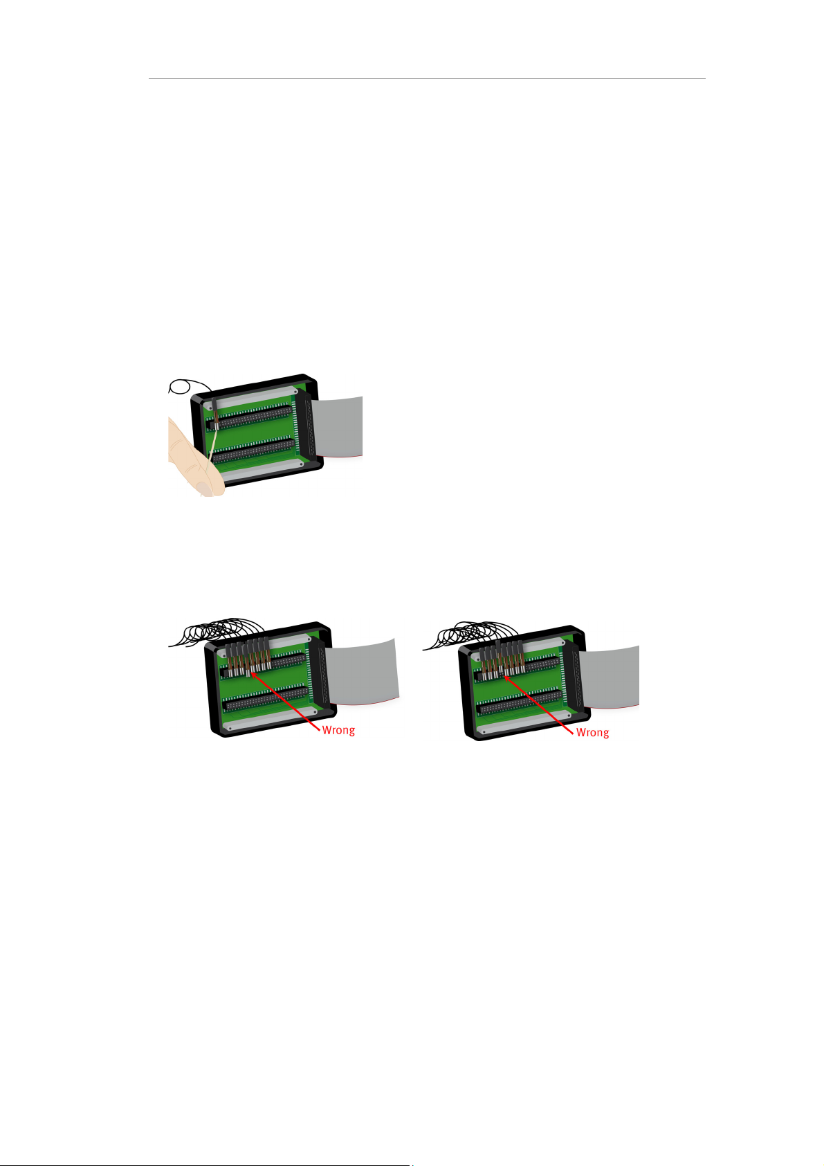
5 Carefully withdraw the faulty electrode from the splitter box. This is best done with a toothpick
or small screwdriver as illustrated below:.
Figure 5-6. Remove a defective electrode from the splitter box
6 Carefully insert the new electrode. Ensure that the four metal pins engage correctly in the splitter
and that the rubber sheathing is aligned and does not protrude.
If the electrode connector is not correctly seated, the electrode will not function.
Figure 5-7. Mistakes when inserting an electrode in the splitter box
7 Set the metal bar back in place with the flat side facing down and secure it with the two small
screws.Put the cover back onto the splitter box and secure it with the center screw.
If, during data acquisition, the corresponding channel signal is flat, or the impedance measurement
is not possible or multiple electrodes exhibit defective signals, confirm that the electrode connector
is seated correctly in the splitter box. Re-align if necessary.
Page 36
Chapter 5 Troubleshooting 36
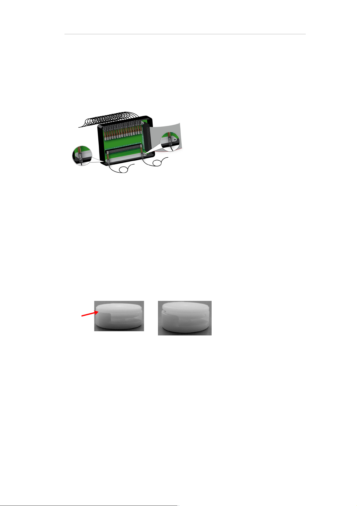
Position of GND and REF electrode
If you replace a faulty GND or REF electrode, observe the positions of these electrodes as illustrated
in the figure below.
Figure 5-8. Insert the reference and ground electrode into the splitter box
The GND and REF electrodes are opposite the EEG electrodes, and have color-coded housings:
GND = black and REF = blue.
Notes on the cable clips
After replacing an electrode, the cable of the old electrode must be removed from the cable clips
and the cable of the new electrode inserted. There are two round cable clips on each harness. A clip
consists of a bottom and a top part.
Carefully insert a small flathead screwdriver or utility knife into the small groove between the
bottom and the top and lightly pry the top open until you here a click.
With one hand, hold the bottom part and cables and with the other hand remove the top.
Then remove the cable of the faulty electrode and insert the cable of the new electrode.
Close the clip and do the same for the other clip.
Page 37

Chapter 6 Maintenance, care and disposal
!
6.1 Maintenance
In principle, the amplifier is maintenance-free. However, it is recommended that you apply the test
signal at regular intervals (e.g. once a month) in order to ensure that it is functioning correctly (see
Section 3.2.3
Factory testing and calibration ensure equipment accuracy and frequency response. Contact Brain
Products GmbH for re-calibration if necessary.
).
37
Repairs or repeat testing as laid down in VDE 0751-1/IEC 62353 may only be carried out by Brain
Products.
If any pins or connections on the product(s) are dirty or if you should notice any damage, return the
product(s) to Brain Products.
6.2 Care
Use a soft, slightly moist cloth to clean the V-Amp and ImpBox.
Notice
Never clean the amplifier and its accessories under running water.
Do not use aggressive or corrosive cleaning agents.
Do not sterilize the products.
Never clean the products when the test subject is connected to them or the USB
cable is still connected.
Page 38

Chapter 6 Maintenance, care and disposal 38
6.3 Disposal
As soon as the product, accessories and cables have reached the end of their service
life , dispose of them in acco rdance with the applicable legislation. In the EU and EFTA,
the WEEE Directive 2002/96/EC on Waste Electrical and Electronic Equipment applies. In Germany, for example, the "ElektroG" additionally governs electrical and
electronic equipment.
Do not dispose of your products, accessories and cables with ordinary household waste.
On request, Brain Products will take back your old products, provided that they are original Brain
Products parts.
Page 39
Appendix A Technical data
V-Amp
Parameter Value
Power supply Via USB
Voltage +5 V ±10 %
Current in stand-by mode Less than 0.5 mA in USB suspend mode
39
Minimal current in active mode
(recording off, LCD off) *
Maximal current in active mode during recording * Less than 450 mA (typically 370 mA)
Data transfer USB 1.1 (USB 2.0)
Supported OS Windows® XP, Vista, 7, 8
Dimensions (mm) 170 x 125 x 30
Weight (g) V-Amp 16: approx. 430 g
*Power data for 16 CH models are described.
Typically 140 mA
Connector: type A/B
full-speed mode
plug-and-play support
V-Amp 8: approx: 400 g
Ambient conditions
Parameter Value
Operation Temperature: 0°C (32°F) to +40°C (104°F)
Humidity: 30 to 90 %, non-condensing
Air pressure: 700 to 1,050 hPa
Transport Temperature: -35 °C (-31 °F) to +65 °C (149 °F)
Humidity: rel. 30 to 95 %, non-condensing
Air pressure: 700 to 1,050 hPa
Storage Temperature: -35 °C (-31 °F) to +65 °C (149 °F)
Humidity: rel. 30 to 95 %, non-condensing
Air pressure: 700 to 1,050 hPa
Page 40

Appendix A Technical data 40
EEG channels for passive electrodes
Parameter Value
Number of channels 8/16 EEG, ground, reference
monopolar
Connectors type Passive electrodes (8/16, ground, reference): 1.5 mm touch-
proof jacks
Active electrodes: 40-way socket for the actiCAP
Input range ±410 mV
Frequency range 0 Hz (DC) – 320 Hz/4 kHz (high-speed mode)
Sampling rates 100 Hz
250 Hz
500 Hz
1,000 Hz
2,000 Hz
5,000 Hz
10,000 Hz
20,000 Hz
Input noise < 1 Vpp (0.5-30 Hz)
Input DC impedance > 100 MOhm
CMRR 100 dB
Impedance Check
(passive electrodes only)
Analog-to-digital conversion Synchronous 2.56 MHz sigma-delta modulation synchronously
Galvanic isolation Reinforced according to IEC60601-1 from PC side and double
Impedance measure independently for each electrode relative
to GND electrode
Range: 1-120 kOhm
Tolerance: 10 %
for all channels, hardware digital filtration and decimation up
to 20,000 Hz, 24 bit.
reinforced from auxiliary channels
Page 41

Mapping of EEG channels (V-Amp 16)
Appendix A Technical data 41
EEG channel Passive electrodes
(touch-proof connectors)
11 6
22 3
33 4
44 1
55 5
66 8
77 7
88 10
99 12
10 10 11
11 11 14
12 12 13
13 13 16
14 14 15
15 15 18
Active electrodes
(40 way connector)
16 16 17
REF REF 19
GND GND 35
Power – - 2, 20, 38
Power + - 9, 27
Page 42

Appendix A Technical data 42
Auxiliary channels
Parameter Value
Number of channels 2 bipolar
Input range ±5 V
Differential impedance > 20 MOhm
Frequency range 0–150 Hz (-3 dB)
Analog-to-digital conversion Multiplexing of auxiliary channels, sigma-delta mod-
ulation, hardware digital filtration and decimation up
to 2,000 Hz, 24 bit.
Sensors power +5 V and -5 V (±5 %) lines.
Current up to 10 mA per channel.
Galvanic isolation Reinforced according to IEC60601-1 from PC side and
double reinforced from EEG channels
No galvanic isolation between auxiliary channels.
Triggers
Parameter Value
Input digital signals 9 Bits
TTL level
Input trigger connector Trigger 1: D-Sub 9, female for Bits 1-8
Trigger 2: 3.5 mm jack plug for Bit 0
Triggers status Synchronously with sample data
max. tolerance +0.5 ms or +1 sample (whichever is
greater)
Galvanic isolation From PC side galvanic isolation is used for reducing
the capacity to ground in case of connected external
triggers sources. Isolation voltage is 200 VDC.
Triggers are reinforced galvanic isolation from the
test subject circuits (EEG and auxiliary channels).
Page 43

Appendix A Technical data 43
ImpBox
Power supply
Parameter Value
Power supply 2 x 1.5 V AA rechargeable battery
Max. operating duration 6 h
Technical data
Impedance measurement range 1 kOhm to 300 kOhm (±15 %)
Injected current < 20 A
Measurement cycle for up to 32 Ch less than 1 sec.
Ambient conditions
Parameter Value
Operating temperature 0 °C (32 °F) to +40 °C (104 °F)
Transport/storage temperature -35 °C (-31 °F) to +65 °C (149 °F)
Humidity rel. 30-95 %, non-condensing
Air pressure 700-1,050 hPa
Page 44

Appendix B Pin-out
-5 V
In- In+
+5 V
GND
2
5
4
3
1
V-Amp
V-Amp is a digital DC amplifier with connectors for:
8 or 16 EEG channels for passive electrodes (plus REF and GND)
16 EEG channels for active electrodes (plus REF, GND and power supply) (V-Amp 16 only)
Auxiliary channels (Aux 1 and Aux 2)
Triggers (Trigger 1 and Trigger 2)
44
Auxiliary connectors
Probes are connected to the AUX inputs.
Figure B-1. AUX connector
Pin Function
1 +5 V power for probe
2 positive terminal of differential input
3 Ground
4 negative terminal of differential input
5 -5 V power for probes
Page 45

Appendix B Pin-out 45
98765
4321
Out
(not used)
Bit 0
GND
Trigger 1 port
The bits in the figures below correspond to the trigger bits in BrainVision Recorder.
For further information, please refer to the BrainVision Recorder User Manual.
Figure B-2. Trigger 1, 9 way digital parallel port (view from top)
Pin Function
1Bit 1
2Bit 2
3Bit 3
4Bit 4
5Bit 5
6Bit 6
7Bit 7
8Bit 8
9GND
Trigger 2 port
Figure B-3. Trigger 2, jack plug (illustrated)
USB Type B (power and data interface)
Page 46

NEW
40 pin connector for actiCAP (V-Amp 16 only)
39
40
F0386
2
1
Pin Function
1EEG Ch1
2 GND power supply
3EEG Ch3
4EEG Ch2
5EEG Ch5
6EEG Ch4
7EEG Ch7
8EEG Ch6
Appendix B Pin-out 46
9 5 VDC power supply
10 EEG Ch8
11 EEG Ch10
12 EEG Ch9
13 EEG Ch12
14 EEG Ch11
15 EEG Ch14
16 EEG Ch13
17 EEG Ch16
18 EEG Ch15
19 REF
20 GND power supply
27 5 VDC power supply
35 Virtual Ground (2,5VDC)
38 GND power supply
21-26, 28-34, 36-37, 39, 40 Not used
ImpBox
Page 47

Appendix B Pin-out 47
39
40
F0024
2
1
40 pin connector for ImpBox
Pin Function
1 Reference for Impedance Measurement (EEG-channel 1)
2 GND power supply
9 3 VDC ±5% power supply
20 GND power supply
27 3 VDC ±5% power supply
35 Virtual GND (2,5VDC)
37 3 VDC ±5% power supply
38 GND power supply
39 GND power supply
40 Control signal
3-8, 10-19, 21-26, 28-34, 36 not used
Page 48

Appendix C Ordering Codes
V-Amp System
V-Amp 8-channel Amplifier System
Article name Article No.
V-Amp 8-channel amplifier BP-01972
V-Amp USB cable BP-01974
48
V-Amp trigger cable BP-245-1550
V-Amp carrying box black BP-01977
Application Suite DVD BP-02000-cd
V-Amp 16-channel Amplifier System
Article name Article No.
V-Amp 16-channel amplifier BP-01973
V-Amp USB cable BP-01974
V-Amp trigger cable BP-245-1550
V-Amp carrying box black BP-01977
Application Suite DVD BP-02000-cd
Page 49

Appendix C Ordering Codes 49
V-Amp Amplifier System + Software
V-Amp 8-channel Amplifier System + BrainVision Recorder + BrainVision Analyzer
Article name Article No.
V-Amp 8-channel amplifier BP-01972
V-Amp USB cable BP-01974
V-Amp trigger cable BP-245-1550
V-Amp carrying box black BP-01977
Application Suite DVD BP-02000-cd
Recorder User Manual BP-00070-me
Recorder & Analyzer V-Amp Edition 1st Lincense, Recorder
& Analysis Software USB only with V-Amp Systems
Recorder & Analyzer USB dongle, black V-Amp Edition BP-00172-VA
V-Amp 16-channel Amplifier System + BrainVision Recorder + BrainVision Analyzer
Article name Article No.
V-Amp 16-channel amplifier BP-01973
V-Amp USB cable BP-01974
V-Amp trigger cable BP-245-1550
V-Amp carrying box black BP-01977
Application Suite DVD BP-02000-cd
Recorder & Analyzer V-Amp Edition 1st Lincense, Recorder
& Analysis Software USB only with V-Amp Systems
Recorder & Analyzer USB dongle, black V-Amp Edition BP-00172-VA
BP-00170-VA
BP-00170-VA
Page 50

Appendix C Ordering Codes 50
BCI Package
Article name Article No.
V-Amp 16-channel amplifier BP-01973
18Ch active Electrodes Set BP-04242-18
actiCAP active Signal electrode for Replacement BP-04243-SIG
actiCAP BP 32Ch Standard Cap with holders (+ 2 add. holders) and chin belt without electrodes
actiCAP Starter Set: SuperVisc gel, chestbelt, measuring
tape and syringe (with needle, washers and brush with
needle, washers and brush)
V-Amp Impedance Box (ImpBox) BP-01982
V-Amp USB cable BP-01974
Trigger Cable BP-245-1550
V-Amp carrying box black BP-01977
BrainVision RecView Basis Module BP-00051
Analyzer HASP HL USB Dongle red BP-00160-U
Recorder USB Dongle blue BP-00060-UR
BCI Package Add-On CD (with samples of BCI applications) BP-02635
Application Suite DVD BP-02000-cd
BP-04251
BP-04259-VISC
 Loading...