

Page 1
UMFPR01G
March 2019
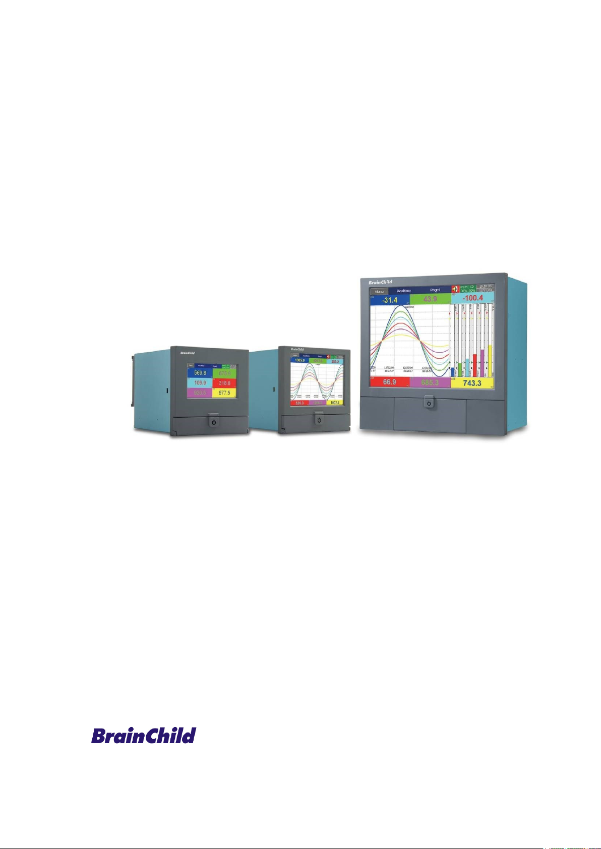
Paperless Recorder
PR10/PR20/PR30
User Manual
Page 2

Page 2 of 479
Safety
This recorder is compliant with the requirements of EN61010-1, UL 61010C-1 & CSA C22.2 No.
24-93. If the equipment is used in a manner not specified by the manufacturer, the protection provided by
the equipment may be impaired. Manufacturer is not liable for any damages incurred to equipment/personal
during installation or use of equipment as explained in this document. User must acquire sufficient
knowledge & skills prior to using equipment in the application and follow all the local standards & regulations
to meet safety requirements.
Warning Symbol
This document contains notices that you should observe to ensure your own personal safety, as
well as to protect the product and connected equipment. These notices are highlighted in the manual by a
warning triangle and are marked as follows.
The danger symbol indicates that death or severe personal injury may result if proper
precautions are not taken. Do not proceed beyond a warning symbol until the indicated conditions are fully
understood and met.
Before connecting the power cord, ensure that the power supply voltage matches the voltage
rating for the instrument.
Make sure to connect the protective grounding to prevent electric shock before turning ON
the power. Never cut off the internal or external protective grounding wire or disconnect the wiring of the
protective grounding terminal. Doing so will pose a potential shock hazard. Do not operate the instrument
when the protective grounding or the fuse might be defective. Also, make sure to check them before
operation.
❖ Do not operate the instrument in the presence of flammable liquids or vapours. Operation
of any electrical instrument in such an environment constitutes a safety hazard.
❖ Some areas inside the instrument have high voltages. Do not remove the cover if the power
supply is connected. The cover should be removed by our qualified personnel only.
❖ Using the instrument in a manner not specified in this manual can damage the instrument’s
protection
❖ Keep signal and supply voltage wiring separated from one another. If this is impractical,
use shielded cables for signal wiring. Double insulation should be used for signal wiring
when the recorder is used with hazardous voltage.
❖ Do not use the recorder where there is high vibration or a high magnetic field. This could
cause damage or error of measurement.
❖ All maintenance or repairs should be carried out with power disconnected to avoid personal
injury or damage to the unit.
❖ In areas with conductive pollution, adequate ventilation, filtering and sealing must be
installed.
❖ When cleaning the recorder, handle carefully and use soft dry cloth. Avoid the use of
abrasives, or any sharp or hard objects which would damage the display.
❖ Do not operate the recorder if any part has been removed or disassembled. Consult your
nearest dealer at once.
❖ Static Electricity: Appropriate precautions must be taken when handling the recorder. The
circuit board components are susceptible to damage caused by electrostatic discharge.
Take static electricity precautions while handling and inserting USB memory into the
recorder.
Page 3

Page 3 of 479
Preface
Original equipment manufacturer reserves the right to change information available in this
document without notice. Manufacturer is not liable for any damages incurred to equipment/personal during
installation or use of equipment as explained in this document. User must acquire sufficient knowledge &
skills prior to using equipment in the application and follow all the local standards & regulations to meet
safety requirements.
Copyright
The documentation and the software included with this product are copyrighted 2016 by
Brainchild Electronic Co. Ltd. All rights are reserved. Brainchild Electronic Co., Ltd. reserves the right to
make improvements in the products described in this manual at any time without notice.
No part of this manual may be reproduced/copied/translated or transmitted in any form or by any
means without the prior written permission of Brainchild Electronic Co., Ltd. The information we supply is
believed to be accurate and reliable as of this printing. However, we assume no responsibility for its use.
Contact Information
Head Office & Factory
Brainchild Electronic Co. Ltd.
209 Chong yang Road, Nangang Dist.,
Taipei 11573, Taiwan
Tel: +886-2-2786-1299 Fax: +886-2-2786-1395
Website: www.brainchildtw.com;
Email: [email protected]; [email protected]
China Sales Office
Brainchild Electronic (Kunshan) Co. Ltd.
Room 405, Building #6, Huamin Gentlefolk Garden
No. 13, Qianjin Central Road, Kunshan City, Jiangsu 215300, China
Tel: +86-512-5511-6133 Fax: +86-512-5511-6113
Email: [email protected] ; [email protected]
Page 4

Page 4 of 479
Table of Contents
1. INTRODUCTION ................................................................................................................................................................ 12
1.1 INTRODUCTION ................................................................................................................................................................ 12
1.2 FEATURES....................................................................................................................................................................... 12
1.2.1 Hardware ............................................................................................................................................................ 12
1.2.2 Firmware ............................................................................................................................................................. 12
1.2.3 PC Software ........................................................................................................................................................ 13
1.2.4 Firmware and Software Features ....................................................................................................................... 13
1.3 COMPARISON OF PR SERIES RECORDERS ........................................................................................................................ 16
1.4 EXPANDABLE INPUT AND OUTPUT CARDS .......................................................................................................................... 16
1.4.1 Analog Input cards (part number AI206 & AI203) ............................................................................................... 17
1.4.2 Relay Output card (RO206) ................................................................................................................................ 17
1.4.3 Digital Input card (DI206) .................................................................................................................................... 17
1.4.4 Combination Relay Output and Digital Input Card (RD233) ............................................................................... 17
1.4.5 Analog Output cards (AO206) ............................................................................................................................ 18
1.4.6 PID Process Control card (PC201) ..................................................................................................................... 18
1.5 COMMUNICATION ............................................................................................................................................................. 18
1.6 EXTERNAL STORAGE MEDIA ............................................................................................................................................. 18
1.7 SMART MECHANISM ......................................................................................................................................................... 19
1.8 ORDERING CODE ............................................................................................................................................................. 20
1.8.1 PR10 Ordering code ........................................................................................................................................... 20
1.8.2 PR20 Ordering code ........................................................................................................................................... 21
1.8.3 PR30 Ordering code ........................................................................................................................................... 23
1.8.4 PID Process Control Card PC201 Ordering code ............................................................................................... 24
1.8.5 Accessories ........................................................................................................................................................ 24
1.9 SPECIFICATIONS .............................................................................................................................................................. 25
1.9.1 General Specifications ........................................................................................................................................ 25
1.9.2 Analog Input Specifications (AI203 & AI206) ...................................................................................................... 26
1.9.3 Digital Input Specifications (DI206 & RD233) ..................................................................................................... 29
1.9.4 Relay Output Specifications (RO206 & RD206) ................................................................................................. 29
1.9.5 Analog Output Specifications (AO206) ............................................................................................................... 29
1.9.6 PID Process Control card Specifications ............................................................................................................ 29
1.9.6.1 Input1 .......................................................................................................................................................................... 29
1.9.6.2 Input2 .......................................................................................................................................................................... 30
1.9.6.3 Input3 (Event Input)..................................................................................................................................................... 30
1.9.6.4 Output1/Output2.......................................................................................................................................................... 31
1.9.6.5 Alarm 1/ Alarm 2 ......................................................................................................................................................... 31
1.9.6.6 Control Mode ............................................................................................................................................................... 31
1.9.6.7 Profiler ......................................................................................................................................................................... 32
1.9.6.8 Digital Filter ................................................................................................................................................................. 32
1.9.7 COMM Module (IF232 and IF485) Specifications ............................................................................................... 32
1.9.8 Standard Ethernet Communication ..................................................................................................................... 32
1.9.9 Real-time Clock .................................................................................................................................................. 32
1.9.9.1 Real time Clock accuracy vs Temperature inside of the housing ............................................................................... 33
1.9.10 Environmental & Physical Specifications....................................................................................................... 33
1.9.11 Approval Standards ....................................................................................................................................... 33
2. INSTALLATION AND WIRING .......................................................................................................................................... 33
2.1 UNPACKING ..................................................................................................................................................................... 34
2.2 DIMENSIONS .................................................................................................................................................................... 34
2.2.1 Panel mounting style .......................................................................................................................................... 34
2.2.1.1 PR10 ........................................................................................................................................................................... 34
2.2.1.2 PR20 ........................................................................................................................................................................... 36
2.2.1.3 PR30 ........................................................................................................................................................................... 38
2.2.2 Portable styles .................................................................................................................................................... 39
2.2.2.1 Bottom Side View of PR20 & PR10 ............................................................................................................................ 40
2.2.2.2 Front Side View of PR20 & PR10 ............................................................................................................................... 40
2.2.2.3 Bottom Side View of PR30 .......................................................................................................................................... 41
2.2.2.4 Front Side View of PR30 ............................................................................................................................................. 41
2.2.2.5 Bottom Stand Clips ..................................................................................................................................................... 42
2.2.2.6 Top Holding Handle .................................................................................................................................................... 42
2.3 INPUT AND OUTPUT CONFIGURATION ................................................................................................................................ 42
Page 5

Page 5 of 479
2.3.1 Analog Input Card (AI206 & AI203) .................................................................................................................... 42
2.3.2 Relay Output card (RO206) ................................................................................................................................ 43
2.3.3 Digital Input card (DI206) .................................................................................................................................... 44
2.3.4 Combination Digital Input and Output card (RD233) .......................................................................................... 44
2.3.5 Analog output cards (AO206) ............................................................................................................................. 45
2.3.6 PID Process Control Module (PC201) ................................................................................................................ 45
2.4 WIRING ........................................................................................................................................................................... 46
2.4.1 Wiring Precautions .............................................................................................................................................. 46
2.4.2 Analog Input Wiring ............................................................................................................................................ 47
2.4.2.1 AI206 wiring ................................................................................................................................................................ 47
2.4.2.2 AI203 Wiring ................................................................................................................................................................ 47
2.4.3 Relay Output Wiring ............................................................................................................................................ 48
2.4.3.1 RO206 ......................................................................................................................................................................... 48
2.4.4 Digital Input Wiring .............................................................................................................................................. 49
2.4.4.1 DI206 ........................................................................................................................................................................... 49
2.4.5 Combination Relay Output and Digital Input Wiring ........................................................................................... 50
2.4.5.1 RD233 ......................................................................................................................................................................... 50
2.4.6 Analog Output Wiring .......................................................................................................................................... 50
2.4.6.1 AO206 ......................................................................................................................................................................... 50
2.4.7 PID Process Control Card Wiring ....................................................................................................................... 51
2.4.7.1 PC201 ......................................................................................................................................................................... 51
2.4.8 RS-232, RS-422, and RS-485 wiring .................................................................................................................. 51
2.4.8.1 RS232 Wiring .............................................................................................................................................................. 51
2.4.8.2 RS422 Wiring .............................................................................................................................................................. 52
2.4.8.3 RS485 Wiring .............................................................................................................................................................. 52
2.5 EXTERNAL MEMORY CARD ............................................................................................................................................... 52
3. BASIC FUNCTIONS OF RECORDERS ............................................................................................................................ 54
3.1 CONFIGURATION .............................................................................................................................................................. 54
3.2 FIRMWARE ...................................................................................................................................................................... 54
3.2.1 Standard Firmware ............................................................................................................................................. 54
3.2.2 Plus 1 Firmware .................................................................................................................................................. 54
3.2.3 Plus 2 Firmware .................................................................................................................................................. 54
3.2.4 Plus 3 Firmware .................................................................................................................................................. 54
3.3 PULSE INPUT THROUGH DIGITAL INPUT .............................................................................................................................. 55
3.4 PID CONTROL WITH RAMP & SOAK PROFILE FUNCTION ...................................................................................................... 55
3.5 ON FIELD CALIBRATION.................................................................................................................................................... 55
3.6 COMMUNICATION WITH THIRD PARTY INTERFACES ............................................................................................................. 55
3.7 WEB SERVER .................................................................................................................................................................. 55
3.8 EMAIL ............................................................................................................................................................................. 55
3.9 HANDWRITING MESSAGES ON HISTORICAL TREND SCREENS .............................................................................................. 56
3.10 CUSTOM DISPLAY SCREEN ......................................................................................................................................... 56
3.11 LOG SPEED FLEXIBILITY.............................................................................................................................................. 56
3.12 SYSTEM CLOCK SYNCHRONIZATION VIA INTERNET ........................................................................................................ 57
3.13 INCREASED SECURITY ................................................................................................................................................ 57
3.14 AUTO OUTPUT TO PRINTER ......................................................................................................................................... 57
3.15 EXTERNAL CHANNELS ................................................................................................................................................ 57
3.16 BATCH ....................................................................................................................................................................... 57
3.17 FDA 21 CFR PART 11 .............................................................................................................................................. 57
3.18 CIRCULAR CHART ....................................................................................................................................................... 57
3.19 MULTILINGUAL LANGUAGES ........................................................................................................................................ 58
3.20 USB BARCODE READER, KEYBOARD AND MOUSE CONNECTIVITY ................................................................................. 58
4. GETTING STARTED .......................................................................................................................................................... 59
4.1 SCREEN NAVIGATION ....................................................................................................................................................... 59
4.1.1 Title Bar .............................................................................................................................................................. 59
4.1.1.1 Menu key ..................................................................................................................................................................... 59
5. CONFIGURATION ............................................................................................................................................................. 76
5.1 CHANNEL ........................................................................................................................................................................ 77
5.1.1 Analog Input ........................................................................................................................................................ 77
5.1.1.2 Desc ............................................................................................................................................................................ 78
5.1.1.3 Type ............................................................................................................................................................................ 78
Page 6

Page 6 of 479
5.1.1.4 Filter ............................................................................................................................................................................ 78
5.1.1.5 Log .............................................................................................................................................................................. 80
5.1.1.6 Sensor ......................................................................................................................................................................... 81
5.1.1.7 Offset ........................................................................................................................................................................... 82
5.1.1.8 Gain ............................................................................................................................................................................. 82
5.1.1.9 Modbus ....................................................................................................................................................................... 82
5.1.1.10 Events ......................................................................................................................................................................... 82
5.1.2 Digital Input ......................................................................................................................................................... 84
5.1.2.2 Desc ............................................................................................................................................................................ 85
5.1.2.3 Type ............................................................................................................................................................................ 85
5.1.2.4 Events ......................................................................................................................................................................... 86
5.1.3 Math Channel ..................................................................................................................................................... 88
5.1.3.2 Desc ............................................................................................................................................................................ 89
5.1.3.3 Type ............................................................................................................................................................................ 89
5.1.3.4 Log .............................................................................................................................................................................. 90
5.1.3.5 Expression .................................................................................................................................................................. 91
5.1.3.6 Scale ........................................................................................................................................................................... 93
5.1.3.7 Modbus ....................................................................................................................................................................... 96
5.1.3.8 Events ......................................................................................................................................................................... 96
5.1.3.9 Examples for Math Channel Application ..................................................................................................................... 98
5.1.4 Analog Output ................................................................................................................................................... 104
5.1.4.1 Desc .......................................................................................................................................................................... 106
5.1.4.2 Type .......................................................................................................................................................................... 106
5.1.4.3 Output ....................................................................................................................................................................... 106
5.1.4.4 Expression ................................................................................................................................................................ 106
5.1.4.5 Modbus ..................................................................................................................................................................... 107
5.1.5 Digital Output .................................................................................................................................................... 107
5.1.5.1 Desc .......................................................................................................................................................................... 108
5.1.5.2 Reverse ..................................................................................................................................................................... 108
5.1.6 External ............................................................................................................................................................. 108
5.1.6.1 Name ......................................................................................................................................................................... 109
5.1.6.2 Desc .......................................................................................................................................................................... 109
5.1.6.3 Type .......................................................................................................................................................................... 109
5.1.6.4 Log ............................................................................................................................................................................ 109
5.1.6.5 Modbus Register Value Conversion ......................................................................................................................... 110
5.1.6.6 Modbus ..................................................................................................................................................................... 111
5.1.6.7 Events ....................................................................................................................................................................... 111
5.2 CONTROLLER ................................................................................................................................................................ 112
5.2.1 Name ................................................................................................................................................................ 113
5.2.2 Parameter ......................................................................................................................................................... 113
5.2.2.1 Parameter Configuration ........................................................................................................................................... 114
5.2.3 Channel ............................................................................................................................................................ 130
5.2.3.1 Name ......................................................................................................................................................................... 131
5.2.3.2 Desc .......................................................................................................................................................................... 131
5.2.3.3 Type .......................................................................................................................................................................... 131
5.2.3.4 Source ....................................................................................................................................................................... 131
5.2.3.5 Log ............................................................................................................................................................................ 131
5.2.3.6 Modbus .................................................................................................................................................................... 132
5.2.3.7 Events ....................................................................................................................................................................... 132
5.2.4 Configuration of Process Control Card ............................................................................................................. 134
5.2.4.1 Heat Only ON-OFF Control ....................................................................................................................................... 134
5.2.4.2 Cool Only ON-OFF Control ....................................................................................................................................... 135
5.2.4.3 Heat Cool Control...................................................................................................................................................... 135
5.2.4.4 Heater Break Alarm................................................................................................................................................... 137
5.2.4.5 Loop Break Alarm ..................................................................................................................................................... 137
5.2.4.6 Sensor Break Alarm .................................................................................................................................................. 137
5.2.4.7 Failure Transfer ......................................................................................................................................................... 138
5.2.4.8 Bumpless Transfer .................................................................................................................................................... 138
5.2.4.9 PV1 Shift ................................................................................................................................................................... 139
5.2.4.10 SP1 Range ................................................................................................................................................................ 140
5.2.4.11 Dwell Timer ............................................................................................................................................................... 140
5.2.4.12 Process Alarms ......................................................................................................................................................... 141
5.2.4.13 Event Input ................................................................................................................................................................ 145
5.2.4.14 Second Set Point ...................................................................................................................................................... 146
5.2.4.15 Second PID Set......................................................................................................................................................... 146
5.2.4.16 Ramp & Dwell ........................................................................................................................................................... 147
5.2.4.17 Remote Set Point ...................................................................................................................................................... 148
5.2.4.18 Differential Control .................................................................................................................................................... 148
Page 7

Page 7 of 479
5.2.4.19 Output Power Limit.................................................................................................................................................... 149
5.2.4.20 Digital Filter ............................................................................................................................................................... 149
5.2.4.21 Auto-Tuning and Manual Tuning ............................................................................................................................... 150
5.2.5 Profile ................................................................................................................................................................ 152
5.2.5.1 Ramp & Dwell ........................................................................................................................................................... 153
5.2.5.2 Name ......................................................................................................................................................................... 154
5.2.5.3 Segments .................................................................................................................................................................. 154
5.2.5.4 Jobs ........................................................................................................................................................................... 157
5.2.5.5 Start/Stop Profile (Ramp &Dwell) .............................................................................................................................. 158
5.2.5.6 Oven Control with Zone Temperature Recording Application .................................................................................. 159
5.3 JOBS ............................................................................................................................................................................ 160
5.3.1 No Action .......................................................................................................................................................... 160
5.3.2 Send Email ....................................................................................................................................................... 160
5.3.3 Pause ................................................................................................................................................................ 160
5.3.4 Start .................................................................................................................................................................. 160
5.3.5 Sound Buzzer ................................................................................................................................................... 160
5.3.6 Dump Data ........................................................................................................................................................ 160
5.3.7 DO Latch On ..................................................................................................................................................... 160
5.3.8 DO Latch Off ..................................................................................................................................................... 160
5.3.9 DO Process ...................................................................................................................................................... 160
5.3.10 Enable Timer ............................................................................................................................................... 161
5.3.11 Disable Timer .............................................................................................................................................. 161
5.3.12 Preset Totalizer ........................................................................................................................................... 161
5.3.13 Reset Totalizer ............................................................................................................................................ 161
5.3.14 Enable Totalizer........................................................................................................................................... 161
5.3.15 Disable Totalizer .......................................................................................................................................... 161
5.3.16 Preset Counter ............................................................................................................................................ 161
5.3.17 Reset Counter ............................................................................................................................................. 161
5.3.18 Inc Counter .................................................................................................................................................. 161
5.3.19 Dec Counter ................................................................................................................................................ 161
5.3.20 Log Report ................................................................................................................................................... 161
5.3.21 Reset MinMaxAve ....................................................................................................................................... 161
5.3.22 Print Historical data ..................................................................................................................................... 161
5.3.23 Print Event List ............................................................................................................................................ 161
5.3.24 Print Report List ........................................................................................................................................... 161
5.3.25 Print Snapshot ............................................................................................................................................. 162
5.3.26 Output Historical Data ................................................................................................................................. 162
5.3.27 Copy Value and Paste Value....................................................................................................................... 162
5.3.28 Select Controller .......................................................................................................................................... 162
5.3.29 Run Profile ................................................................................................................................................... 162
5.4 DISPLAY ........................................................................................................................................................................ 162
5.4.1 Name ................................................................................................................................................................ 163
5.4.2 Mode ................................................................................................................................................................. 163
5.4.3 Speed ............................................................................................................................................................... 163
5.4.4 Direction ............................................................................................................................................................ 164
5.4.5 Background ....................................................................................................................................................... 164
5.4.6 Print Enable ...................................................................................................................................................... 164
5.4.7 Trend Graph Scale ........................................................................................................................................... 164
5.4.8 Pen ................................................................................................................................................................... 165
5.4.8.1 Channel ..................................................................................................................................................................... 165
5.4.8.2 Color .......................................................................................................................................................................... 165
5.4.8.3 Width ......................................................................................................................................................................... 165
5.4.8.4 Range Low ................................................................................................................................................................ 165
5.4.8.5 Range High ............................................................................................................................................................... 165
5.4.8.6 Reference points ....................................................................................................................................................... 165
5.4.8.7 Trend Graph scale position ....................................................................................................................................... 166
5.4.8.8 Status Bar ................................................................................................................................................................. 166
5.5 BATCH .......................................................................................................................................................................... 168
5.5.1 Name ................................................................................................................................................................ 168
5.5.1.1 Lot Number ............................................................................................................................................................... 168
5.5.2 Desc .................................................................................................................................................................. 168
5.5.3 Example for Batch Application .......................................................................................................................... 169
5.5.4 How to view batch data in Recorder ................................................................................................................. 169
5.5.5 How to Dump Batch data to external USB memory .......................................................................................... 170
Page 8

Page 8 of 479
5.6 START / STOP ............................................................................................................................................................... 171
5.6.1 Start .................................................................................................................................................................. 171
5.6.2 Stop .................................................................................................................................................................. 171
5.7 TIMER ........................................................................................................................................................................... 172
5.7.1 Type .................................................................................................................................................................. 172
5.7.1.1 Countdown ................................................................................................................................................................ 173
5.7.1.2 Repeat Countdown ................................................................................................................................................... 173
5.7.1.3 Daily .......................................................................................................................................................................... 173
5.7.1.4 Weekly ...................................................................................................................................................................... 173
5.7.1.5 Monthly ...................................................................................................................................................................... 173
5.7.2 Action ................................................................................................................................................................ 173
5.7.3 Job1, Job2 ........................................................................................................................................................ 173
5.7.4 Timer Example-1 .............................................................................................................................................. 173
5.7.5 Timer Example-2 .............................................................................................................................................. 173
5.7.5.1 Timer Example-3 ....................................................................................................................................................... 174
5.8 CLOCK .......................................................................................................................................................................... 174
5.8.1 Date Style ......................................................................................................................................................... 174
5.8.2 Time Zone ......................................................................................................................................................... 175
5.8.3 Synchronize via Internet ................................................................................................................................... 175
5.8.4 Date / Time ....................................................................................................................................................... 175
5.8.5 Summer time .................................................................................................................................................... 175
5.9 COMMUNICATION ........................................................................................................................................................... 175
5.9.1 Ethernet ............................................................................................................................................................ 175
5.9.2 Serial ................................................................................................................................................................. 176
5.9.3 Modbus Server / Slave ..................................................................................................................................... 176
5.9.4 Modbus Client/Master ....................................................................................................................................... 176
5.9.4.1 Connections .............................................................................................................................................................. 176
5.9.4.2 Commands ................................................................................................................................................................ 177
5.9.4.3 Sample Rate ............................................................................................................................................................. 178
5.9.5 Email ................................................................................................................................................................. 178
5.9.6 Example for IO Modules as External Channels ................................................................................................ 180
5.9.7 Example for Controller as External Channels ................................................................................................... 183
5.9.8 Example for SIO Module as External Channel via PC-E .................................................................................. 186
5.9.9 Example for Recorder as Modbus Slave .......................................................................................................... 190
5.10 INSTRUMENT ............................................................................................................................................................ 192
5.10.1 Name ........................................................................................................................................................... 192
5.10.2 Language..................................................................................................................................................... 192
5.10.3 Security........................................................................................................................................................ 192
5.10.3.1 Logout ....................................................................................................................................................................... 192
5.10.3.2 Password validity ...................................................................................................................................................... 193
5.10.3.3 Security Level of Functions ....................................................................................................................................... 193
5.10.4 Batch Control ............................................................................................................................................... 193
5.10.5 Volume ........................................................................................................................................................ 193
5.10.6 Tool Bar ....................................................................................................................................................... 193
5.10.7 Scan Page ................................................................................................................................................... 193
5.10.8 LCD ............................................................................................................................................................. 193
5.10.9 Storage ........................................................................................................................................................ 193
5.10.10 Data Transfer............................................................................................................................................... 194
5.10.10.1 Show Message at the End ........................................................................................................................................ 194
5.10.11 Custom Page ............................................................................................................................................... 194
5.10.11.1 Power on ................................................................................................................................................................... 194
5.10.12 Setup Start-up Image .................................................................................................................................. 194
5.10.12.1 Procedure to Setup a Start-up Image ....................................................................................................................... 194
5.11 SECURITY ................................................................................................................................................................ 195
5.11.1 Normal ......................................................................................................................................................... 195
5.11.2 CFR-21 ........................................................................................................................................................ 195
5.11.2.1 User Account ............................................................................................................................................................. 195
5.12 DEMO ...................................................................................................................................................................... 196
5.13 AUTO-OUTPUT ......................................................................................................................................................... 196
5.13.1 Setup Printer................................................................................................................................................ 197
5.13.2 Print Header ................................................................................................................................................ 198
5.13.3 Title .............................................................................................................................................................. 198
5.13.4 Historical Data ............................................................................................................................................. 198
Page 9

Page 9 of 479
5.13.5 Report Data ................................................................................................................................................. 198
5.13.6 Output Files ................................................................................................................................................. 198
5.13.7 USB Printer Configuration ........................................................................................................................... 198
5.13.8 Network Printer Configuration ..................................................................................................................... 198
5.13.9 Sample Configuration of Printer .................................................................................................................. 199
5.14 SYSTEM INFORMATION .............................................................................................................................................. 202
5.14.1 Firmware Upgrade ....................................................................................................................................... 202
5.14.2 Touch Screen Calibration ............................................................................................................................ 203
5.14.2.1 Batch Example-1 ....................................................................................................................................................... 204
5.15 CALIBRATE............................................................................................................................................................... 207
5.15.1 Calibrate an AI with 0-5V ............................................................................................................................. 209
5.15.2 Calibrate an AI with K type Thermocouple ................................................................................................. 211
5.15.3 Calibrate an AI with Pt100 RTD................................................................................................................... 213
5.15.4 Calibrate an AO with 4 to 20 mA ................................................................................................................. 216
5.15.5 Calibrate an AO with 0 to 10 V .................................................................................................................... 220
5.16 PROCEDURE TO UPGRADE AND RESTORE FACTORY DEFAULT SETTINGS ..................................................................... 223
6. PC BASED SOFTWARE ................................................................................................................................................. 225
6.1 FREE BASIC SOFTWARE ................................................................................................................................................. 225
6.1.1 Historical Viewer Software Installation .............................................................................................................. 225
6.1.1.1 System Requirements ............................................................................................................................................... 225
6.1.1.2 Software Installation .................................................................................................................................................. 225
6.1.1.3 Uninstallation of Software ......................................................................................................................................... 228
6.1.2 Start and Exit .................................................................................................................................................... 228
6.1.3 Historical Viewer ............................................................................................................................................... 228
6.1.3.1 Historical Viewer-Tool Bar ........................................................................................................................................ 228
6.1.3.2 Historical Viewer-Menu Bar ...................................................................................................................................... 230
6.1.3.3 Configuration Viewer-Tool Bar .................................................................................................................................. 235
6.1.3.4 Configuration Viewer-Menu Bar ................................................................................................................................ 236
6.1.3.5 Create a New Project ................................................................................................................................................ 238
6.1.3.6 Open an Existing Project .......................................................................................................................................... 240
6.1.3.7 Automatic Import of Data .......................................................................................................................................... 242
6.1.3.8 Automatic Import and Export of Data ........................................................................................................................ 243
6.1.3.9 Multiple Projects Automatic Import and Export of Data ............................................................................................ 244
6.2 EXTENSIVE SOFTWARE .................................................................................................................................................. 245
6.2.1 Data Acquisition Studio Software Installation ................................................................................................... 245
6.2.1.1 System Requirements ............................................................................................................................................... 245
6.2.1.2 Software Installation .................................................................................................................................................. 245
6.2.1.3 Uninstallation of Software ......................................................................................................................................... 247
6.2.2 Start and Exit .................................................................................................................................................... 247
6.2.3 Real Time Viewer ............................................................................................................................................. 247
6.2.3.1 Real Time Viewer – Tool Bar .................................................................................................................................... 247
6.2.3.2 Real Time Viewer – Menu Bar .................................................................................................................................. 248
6.2.3.3 Real-time Configuration Viewer-Tool Bar ................................................................................................................. 251
6.2.3.4 Create a New Project ................................................................................................................................................ 267
6.2.3.5 Open an Existing Project .......................................................................................................................................... 272
6.2.3.6 Add a Device to the Existing Device ......................................................................................................................... 273
6.2.3.7 PR-DAQ RS485 Communication .............................................................................................................................. 274
6.2.3.8 PR-DAQ Ethernet Communication ........................................................................................................................... 278
6.2.4 Dynamic Data Exchange (DDE) ....................................................................................................................... 282
6.2.4.1 Procedure to find the tag number for the tag name to use in DDE applications ....................................................... 284
6.2.4.2 DDE with 3rd party applications ................................................................................................................................. 284
6.2.5 Configuration of Recorder ................................................................................................................................. 285
6.2.5.1 On the Recorder........................................................................................................................................................ 285
6.2.5.2 Software via Ethernet port ........................................................................................................................................ 285
6.2.5.3 Removable Media ..................................................................................................................................................... 287
6.3 CUSTOM SCREEN EDITING SOFTWARE - PANEL STUDIO ................................................................................................... 291
6.3.1 Panel Studio Software Installation .................................................................................................................... 292
6.3.1.1 System Requirements ............................................................................................................................................... 292
6.3.1.2 Software Installation .................................................................................................................................................. 292
6.3.1.3 Uninstallation of Software ......................................................................................................................................... 294
6.3.2 Start and Exit .................................................................................................................................................... 294
6.3.3 Project status .................................................................................................................................................... 294
6.3.4 Create new project ............................................................................................................................................ 295
6.3.5 Menu bar ........................................................................................................................................................... 296
Page 10

Page 10 of 479
6.3.5.1 File ............................................................................................................................................................................ 296
6.3.5.2 Edit ............................................................................................................................................................................ 299
6.3.5.3 Format ....................................................................................................................................................................... 299
6.3.5.4 View .......................................................................................................................................................................... 302
6.3.5.5 Objects ...................................................................................................................................................................... 303
6.3.5.6 Project ....................................................................................................................................................................... 304
6.3.6 Standard bar ..................................................................................................................................................... 304
6.3.7 Format bar ........................................................................................................................................................ 305
6.3.8 Project Explorer ................................................................................................................................................ 306
6.3.8.1 Screen ....................................................................................................................................................................... 306
6.3.9 Tool box ............................................................................................................................................................ 309
6.3.9.1 Basic Objects ............................................................................................................................................................ 309
6.3.9.2 Enhanced Objects ..................................................................................................................................................... 351
6.3.9.3 Graphics .................................................................................................................................................................... 370
6.3.9.4 Symbol Factory ......................................................................................................................................................... 378
6.3.9.5 Project Tools ............................................................................................................................................................. 386
7. WEBSERVER .................................................................................................................................................................. 390
7.1 REQUIREMENTS ............................................................................................................................................................. 390
7.2 HOW TO CONFIGURE WEB SERVER SETTINGS.................................................................................................................. 391
7.2.1 How to Configure Static IP Address ................................................................................................................. 391
7.2.2 How to Enable Web Server .............................................................................................................................. 392
7.3 HOW TO VIEW RECORDER DATA IN PC VIA WEBSERVER: ................................................................................................. 393
8. MODBUS COMMUNICATION ......................................................................................................................................... 402
8.1 MODBUS ADDRESS MAPPING ......................................................................................................................................... 402
8.1.1 Input Register (3xxxxx) Parameter Table for Modbus RTU Slave / TCP Server .............................................. 402
8.1.1.1 AI / DI / DO / AO Channel Data (Integer Type) ......................................................................................................... 402
8.1.1.2 AI / DI / DO / AO Channel Data (Float Type) ............................................................................................................ 404
8.1.1.3 Math Channel Data (Integer Type) ........................................................................................................................... 406
8.1.1.4 Math Channel Data (Float Type) ............................................................................................................................... 409
8.1.1.5 PID Process Control Module Data (Integer Type) .................................................................................................... 410
8.1.1.6 PID Process Control Module Data (Float Type) ....................................................................................................... 420
8.1.1.7 System Information (Integer Type) ........................................................................................................................... 428
8.1.1.8 System Information (Float Type) ............................................................................................................................... 428
8.1.2 Holding Register (4xxxxx) Parameter Table for Modbus RTU Slave / TCP Server .......................................... 429
8.1.2.1 External Channels 2 Bytes Data (Integer Type) ....................................................................................................... 429
8.1.2.2 External Channels 4 Bytes Data (Integer Type) ....................................................................................................... 431
8.1.2.3 External Channels 4 Bytes Data (Float Type) .......................................................................................................... 434
8.1.3 Holding Register Parameter Table for Remote Command ............................................................................... 436
8.1.3.1 Command Data ......................................................................................................................................................... 436
8.1.3.2 Scale Low (DWord Type) .......................................................................................................................................... 444
8.1.3.3 Scale High (DWord Type) ......................................................................................................................................... 453
8.1.3.4 Others (Word Type) .................................................................................................................................................. 465
8.2 MODBUS COMMUNICATION ............................................................................................................................................. 465
8.2.1 Read Input Registers (Function 0x04) .............................................................................................................. 465
8.2.2 Preset (Write) Multiple Registers (Function 0x10) ............................................................................................ 466
8.2.3 Placing the CRC into message ......................................................................................................................... 466
8.3 SAMPLE CODE............................................................................................................................................................... 467
8.3.1 CRC Generation Function ................................................................................................................................ 467
8.3.2 Read Data Function .......................................................................................................................................... 468
8.3.3 Convert Data Function ...................................................................................................................................... 469
8.3.4 Read AI Function .............................................................................................................................................. 469
8.3.5 Read Math Function ......................................................................................................................................... 470
8.3.6 Read DI Function .............................................................................................................................................. 471
8.3.7 Read AO Function ............................................................................................................................................ 472
8.3.8 Read DO Function ............................................................................................................................................ 472
8.3.9 Read External Function .................................................................................................................................... 473
8.4 APPENDIX ..................................................................................................................................................................... 473
8.4.1 Modbus RTU Slave / TCP Server Register data type table .............................................................................. 473
8.4.2 Inquire AI range ................................................................................................................................................ 473
8.4.3 AI Conversion Example .................................................................................................................................... 474
8.4.4 Math Conversion Sample ................................................................................................................................. 474
8.4.4.1 Transformation Disable ............................................................................................................................................. 475
8.4.4.2 Transformation as value ........................................................................................................................................... 475
Page 11

Page 11 of 479
8.4.4.3 Transformation as Math Channel .............................................................................................................................. 476
8.4.5 AO Conversion Example .................................................................................................................................. 476
8.4.6 External Channel Conversion for AI channel .................................................................................................... 477
8.4.7 External Channel Conversion for DI and DO channel ...................................................................................... 477
8.4.8 External Channel Conversion for AO channel .................................................................................................. 478
8.4.9 External Channel Conversion for Math channel ............................................................................................... 478
Page 12
Page 12 of 479
1. Introduction
1.1 Introduction
The new generation PR series paperless recorder has many outstanding features to meet the
industry requirements.
1.2 Features
1.2.1 Hardware
The PR series hardware has the following unique features.
❖ Available in three display sizes 4.3”, 5.6〞and 12.1”
❖ PR10, with a 4.3” display, with 3 or 6 universal analog inputs and 24 Optional External Channels
❖ PR20, with a 5.6” display, with 6, 12, 18 or 24 universal analog inputs and 48 Optional External
Channels
❖ PR30, with a 12.1” display, with 6, 12, 18, 24, 30, 36, 42 or 48 universal analog inputs and 96
Optional External Channels
❖ High resolution TFT Colour LCD display with Touch screen
❖ 100 millisecond sampling rate and data logging
❖ PID Process Control card (PC201) to control the process.
❖ High accuracy 24-bit A-D Analog Input
❖ 16-bit D-A Analog Output
❖ Pulse input through Digital input, maximum 100 Hz.
❖ Plug & play I/O cards (AI, AO, DI, and DO) for easy expansion.
❖ On-board SD card slot for external storage.
❖ Two USB Host Ports for external storage and printer connectivity
❖ Ethernet as standard with optional RS-232 or RS422/RS485 communication
❖ IP65 water-resistant
1.2.2 Firmware
The PR series recorder has 4 different versions of firmware for the user to select as per the
application requirement.
1. Standard Firmware
2. Plus 1 Firmware
3. Plus 2 Firmware
4. Plus 3 Firmware
Page 13

Page 13 of 479
1.2.3 PC Software
The PR series has the below user-friendly software for configuration, analysis, data acquisition
and custom display
1. Free Basic Software Historical Viewer for configuration and analysis
2. Extensive Software Data Acquisition Studio for configuration, analysis and data acquisition
on PC.
3. Panel Studio Software for Custom display
1.2.4 Firmware and Software Features
The below are the unique features of PR series different firmware.
❖ Circular Chart in PR30
❖ Panel Studio Software for editing and customizing display pages.
❖ Display values in Digital, Trend, Bar graph and mix format.
❖ Real time and Historical Trends
❖ Real time and Historical Alarms
❖ Event management, Jobs linked with events
❖ Reports (Daily, Weekly and Monthly)
❖ Timers, Counters, Totalizers, Math channels
❖ FDA 21 CFR part 11 compliance
❖ Customized messages for alarms
❖ Alarms by email directly from paperless recorder
❖ Batch control, log data in batches
❖ 100 milliseconds data logging and historical data archival tools
❖ Display pages rotation
❖ Start/Stop data logging functions which can be linked with real time clock or events
❖ Search data with reference Time, Period, Tag, Event, Alarm, Remark, Handwrite
❖ Export data to Excel and database format (*.csv only)
❖ Web server
❖ Handwriting function in historical data
❖ PID control with Profile function
❖ Multiple Languages for users to select
❖ Data logging by value change or time base
❖ Dynamic Data Exchange via PC software
❖ On Field Calibration
❖ Direct Printer Connectivity with PDF Printer included
❖ USB Barcode Reader Connectivity for Data Entry
❖ USB Keyboard and Mouse Connectivity
❖ Clock Synchronization via Internet
Page 14
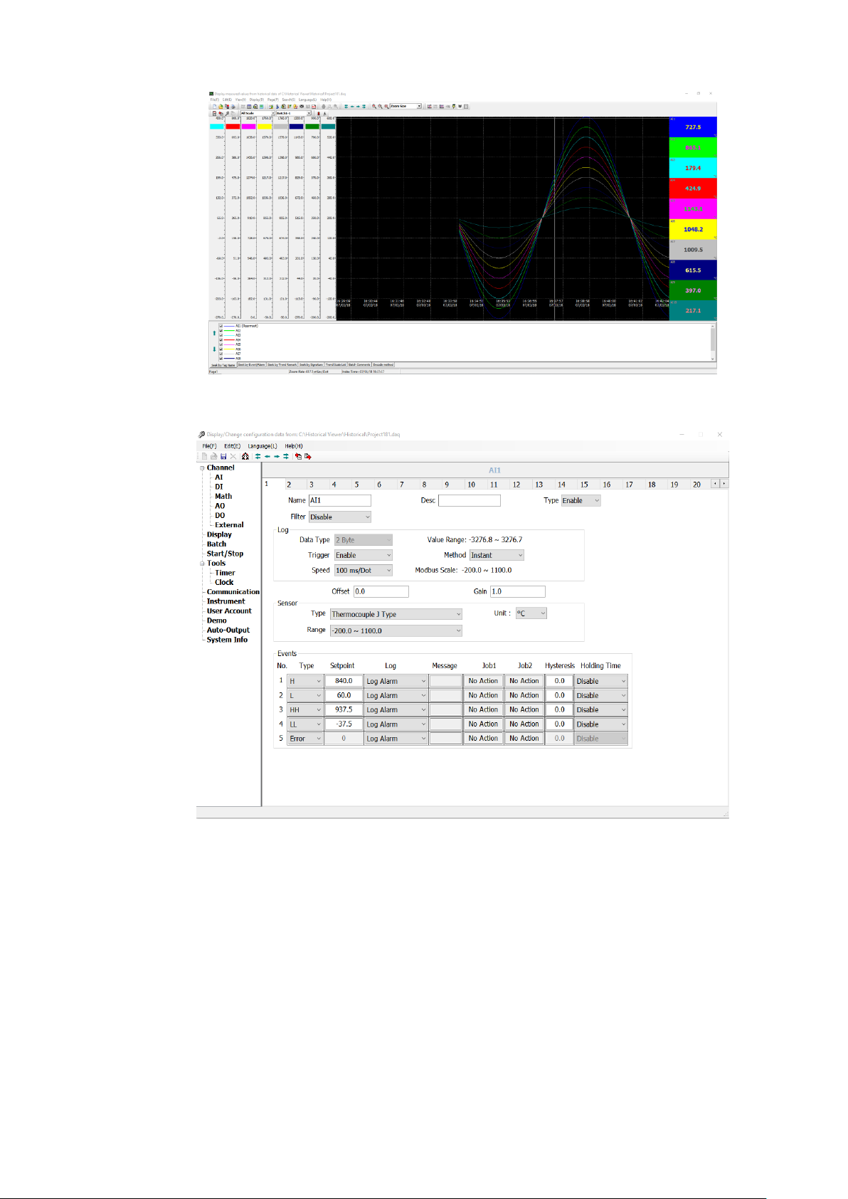
Page 14 of 479
1-1 Historical Viewer Software
1-2 Configuration Viewer Software in Historical Viewer Software
Page 15
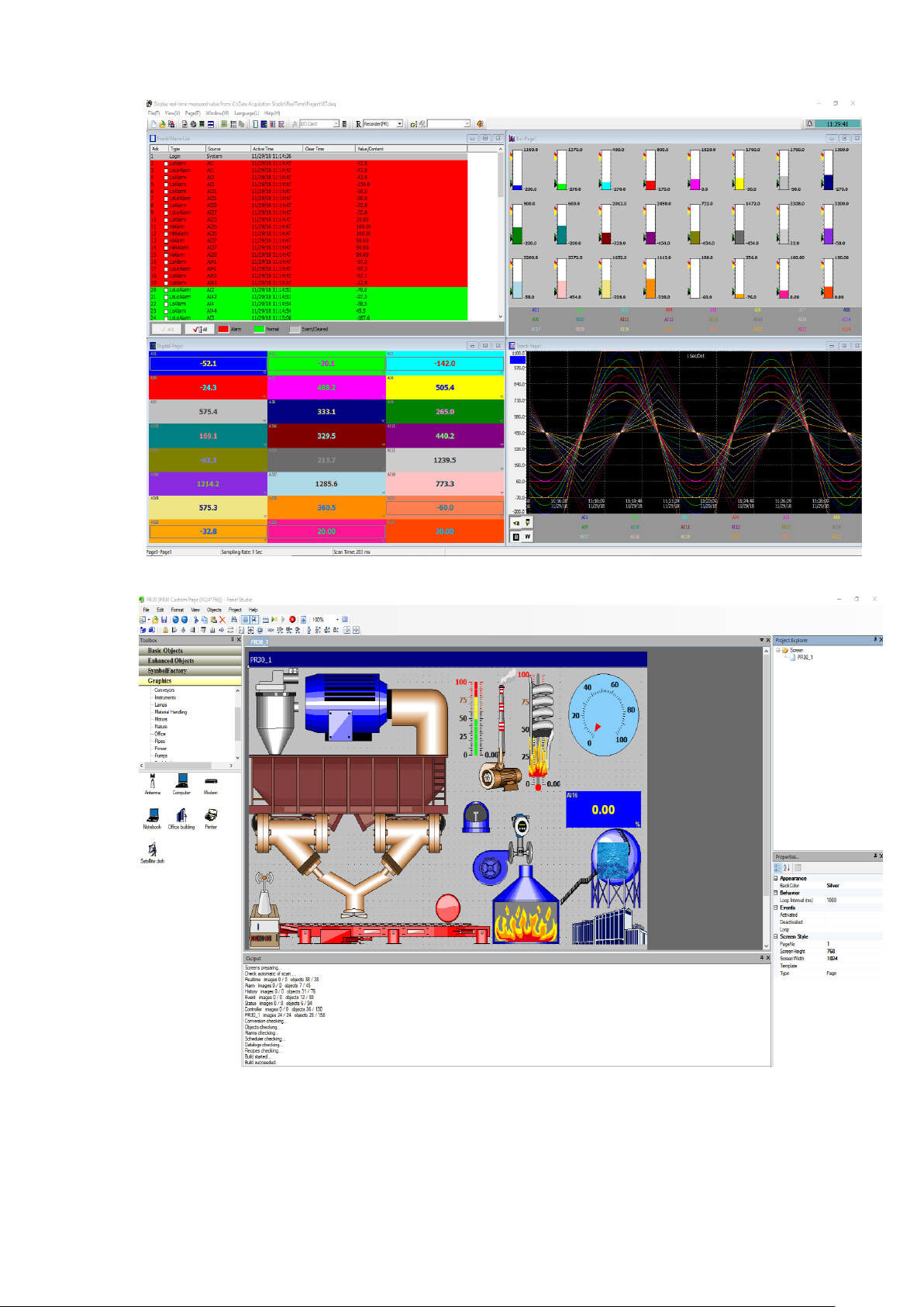
Page 15 of 479
1-3 Real Time Viewer in Data Acquisition Studio Software
1-4 Panel Studio Software for Custom Display
Page 16
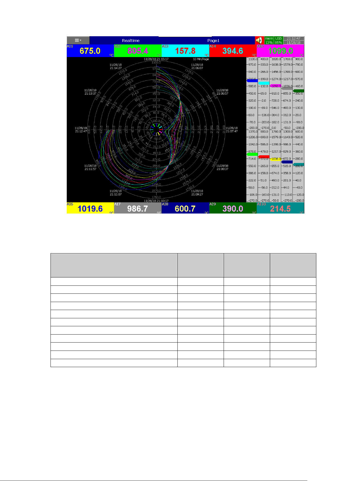
Page 16 of 479
1-5 Circular Chart in PR30
1.3 Comparison of PR series Recorders
The below table show the differences between different models of PR series recorder.
Description
PR10
PR20
PR30
Display Size
4.3”
5.6”
12.1”
Analog Inputs (Maximum)
6
24
48
Analog Outputs (Maximum)
6 6 12
Digital Inputs (Maximum)
24
24
24
Relay Outputs (Maximum)
24
24
24
PID Process Control Card
4 4 8
Math Channels (Maximum)
15
40
60
External Channels (Other devices via Modbus)
24
48
96
Total Pages
8
20
21
Pens/Page (Maximum)
6 6 10
Batches (Maximum)
1 1 1
1-1 Comparison of PR10, PR20 and PR30
1.4 Expandable Input and Output cards
There are 4 rear expansion slots in PR10 and PR20 and 16 rear expansion slots in PR30
available for expansion with the following plug and play I/O Cards.
Page 17
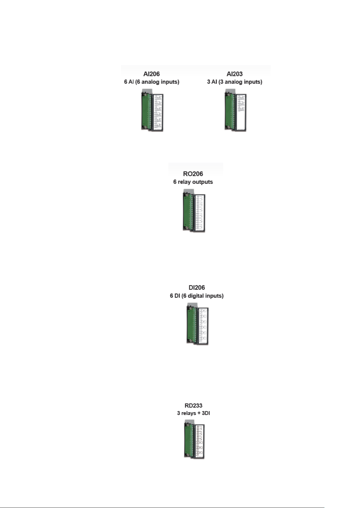
Page 17 of 479
1.4.1 Analog Input cards (part number AI206 & AI203)
These two cards are used for 3 or 6-channel analog inputs. Each input is isolated from each
other to avoid noise and to ensure stable measurement.
1.4.2 Relay Output card (RO206) Each card includes 6 relay outputs. The relay contacts are rated 5 Amp/240 VAC.
1.4.3 Digital Input card (DI206)
Each card includes 6 channels. Logic Low: -5V minimum, 0.8V maximum, Logic High: 3.5V
minimum, 24V maximum
1.4.4 Combination Relay Output and Digital Input Card (RD233)
Each Card includes 3 digital Inputs and 3 Relay Outputs. For Digital Inputs, Logic Low: -5V
minimum, 0.8V maximum, Logic High: -3.5V minimum, 24V maximum. For Relay Outputs, the Contacts are
rated 5 Amp/240 VAC
Page 18
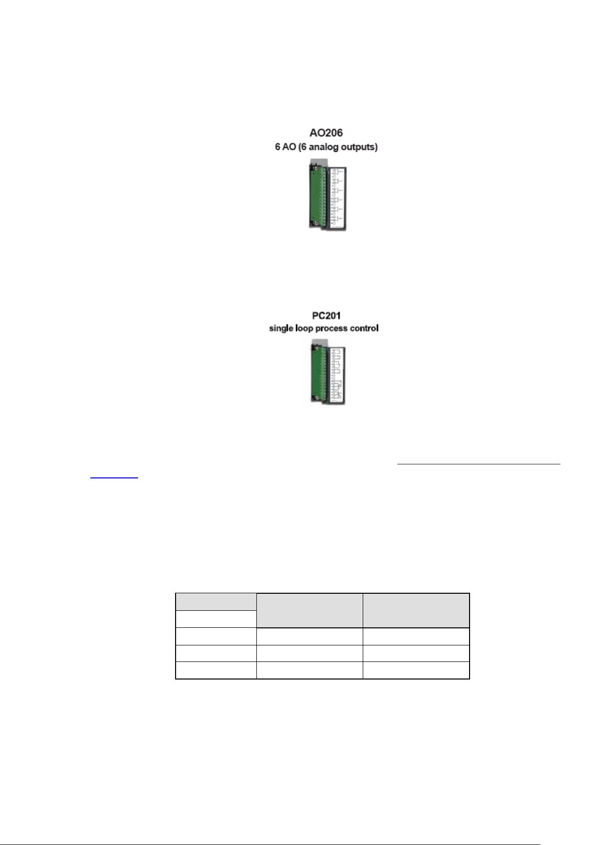
Page 18 of 479
1.4.5 Analog Output cards (AO206)
Each card includes 6 channels. They are used for 4-20mA, 0-20mA current output, 0-5V, 1-5V,
0-10VDC voltage output.
1.4.6 PID Process Control card (PC201)
Each card includes one single loop PID process control function with ramp and soak profile
segment.
1.5 Communication
The standard communication interface is Ethernet with protocol IEEE 802.3 – 10/100 Base T.
Other options are RS-232 / RS-422 / RS-485. Details are explained in Chapter 2.4.8 - RS-232, RS-422, RS-
485 wiring.
1.6 External Storage media
The recorder has 256MB internal memory to store the data. There are two types of External
storage media available for the recorder to dump the stored data from internal memory. They are SD card
and USB. Only one storage media can be used at a time in the recorder.
If the recorder is used with 6-channel inputs, the below chart shows the maximum no of days
historical data can be stored based on available memory.
SD card
16GB
32GB
Log speed
1 second
15, 808 days
31,616 days
10 seconds
158,032 days
316,064 days
120 seconds
1,896,304 days
3,792,608 days
* The above is an approximation, each record of data uses 2 or 4 bytes of memory depending on the data
type.
For ex: Selected data size = 2 bytes
If the Log Speed (the recording speed of measured data) is set to the speed at 1 second per
data, then for a six channels, a 16GB SD Card will last approximately 15, 808 days [16GB / (2 bytes x 24
hours x 60 minutes x 60 seconds x 6 Channels].
The following formula is to calculate how many days a USB disk can do saving before it is full.
Page 19
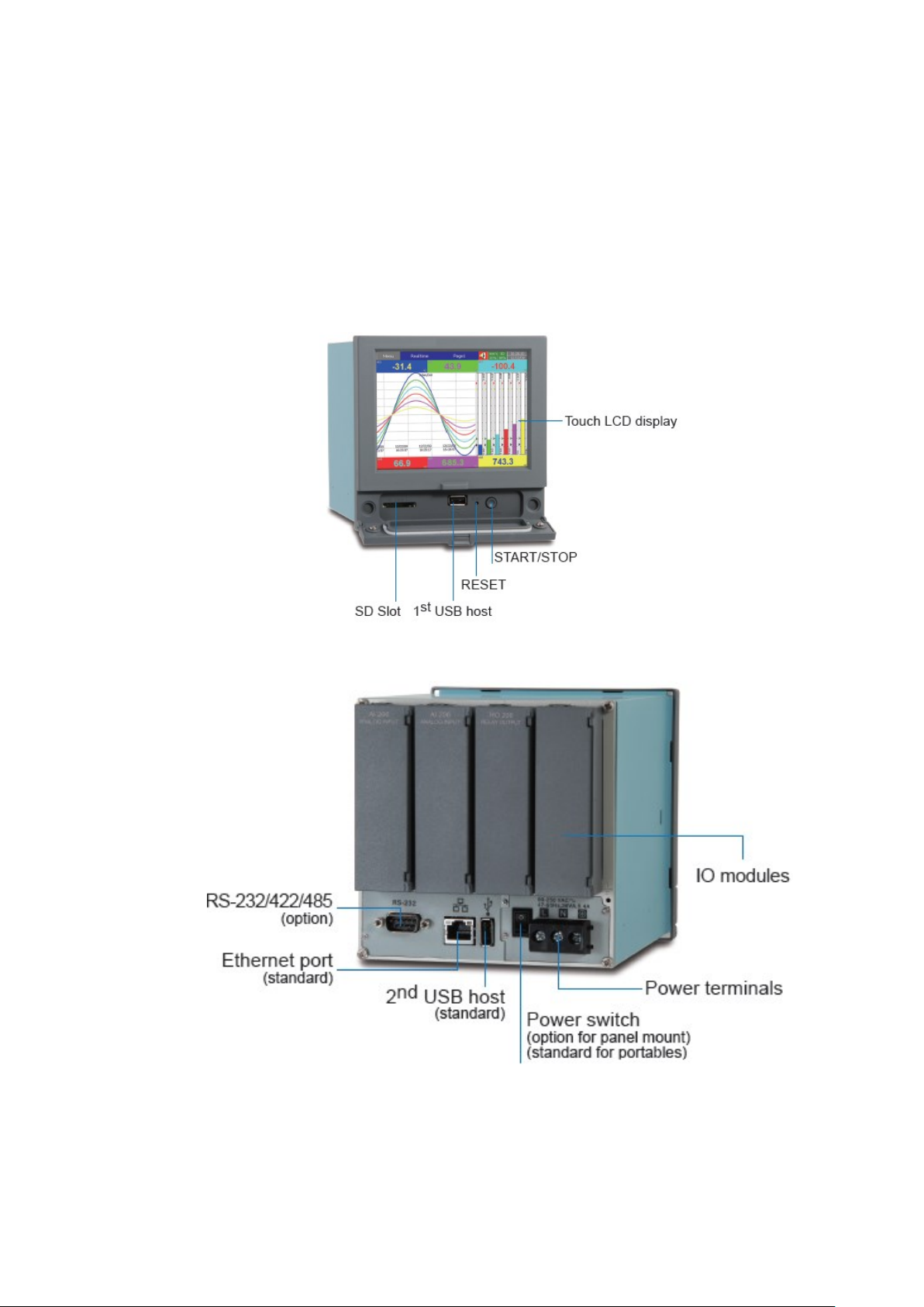
Page 19 of 479
No of days = (The capacity of SD card memory x Log Speed) / (2 x # of hours per day x 60 x 60 x Number
of channels)
If the user is using USB to dump the data then it is necessary to insert USB memory back to
recorder after loading recorded data onto PC. Otherwise the dumping process will fail and the oldest data
will be deleted once the internal memory is full. The recorder will do automatic dumping process when the
internal memory is occupied by 85%.
1.7 Smart Mechanism
The recorded data is stored in the manufacturer’s special binary format. It is not possible to
manipulate or modify the recorded data. This feature fully guarantees the security of the data.
Page 20
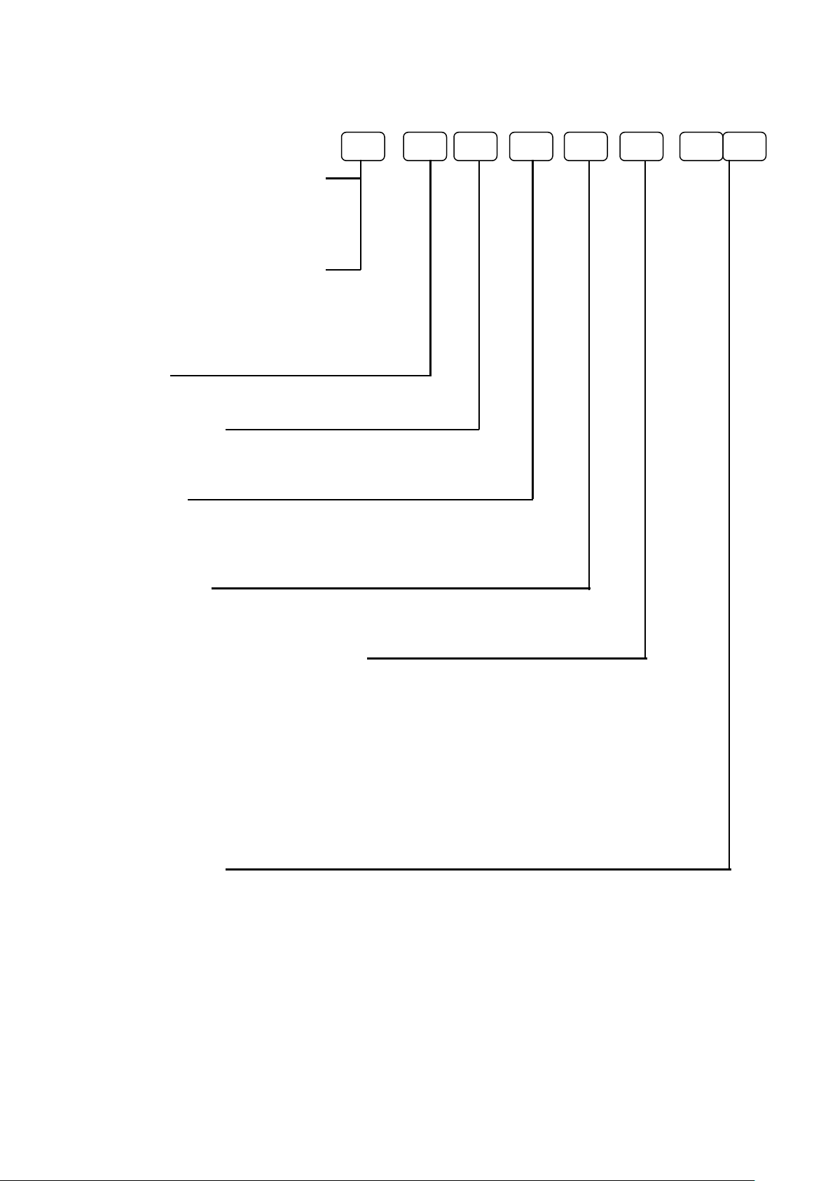
Page 20 of 479
1.8 Ordering Code
1.8.1 PR10 Ordering code
PR1003 (3 Analog Inputs)
Other Inputs and Outputs
0: none
6: 3 relays + 3 DI
PR1006 (6 Analog Inputs)
Other Inputs and Outputs
0: none
1: 6 relays
3: 6DI
6: 3 relays + 3 DI
7: 6 relays + 6 DI
Power
A: 90-250 VAC, 50/60 Hz
D: 11-36 VDC
Communication
0: standard Ethernet interface
1: Ethernet + RS-232
2: Ethernet + RS-422/485
Firmware
0: Standard Version with Mathematic Functions
1: Plus Version 1 with external channels, batch & FDA 21 CFR part 11
2: Plus Version 2 with editable custom display and Panel Studio software
3: Plus Version 3- includes Plus Version 1+2 above
PC Software
1: Free Basic Software of Historical Viewer and Configuration
2: Extensive software Data Acquisition Studio
(Real Time Viewer + Historical Viewer + Configuration)
Mounting types, Power Cord & Switch
0: panel mount, no power cord, no power switch
1: panel mount, no power cord, power switch
2: portable, UL & CSA power cord, power switch
3: portable, VDE power cord, power switch
4: portable, SAA power cord, power switch
5: portable, BS power cord, power switch
6: portable, no power cord, power switch
7: Panel mount, UL & CSA power cord, power switch
8: Panel mount, VDE power cord, power switch
9: Panel mount, SAA power cord, power switch
A: Panel mount, BS power cord, power switch
Special options
00: none
S1: 16G SD card
S2: 32G SD card
Note:
DI- Digital Input
PID Process Control card can be purchased separately.
Page 21
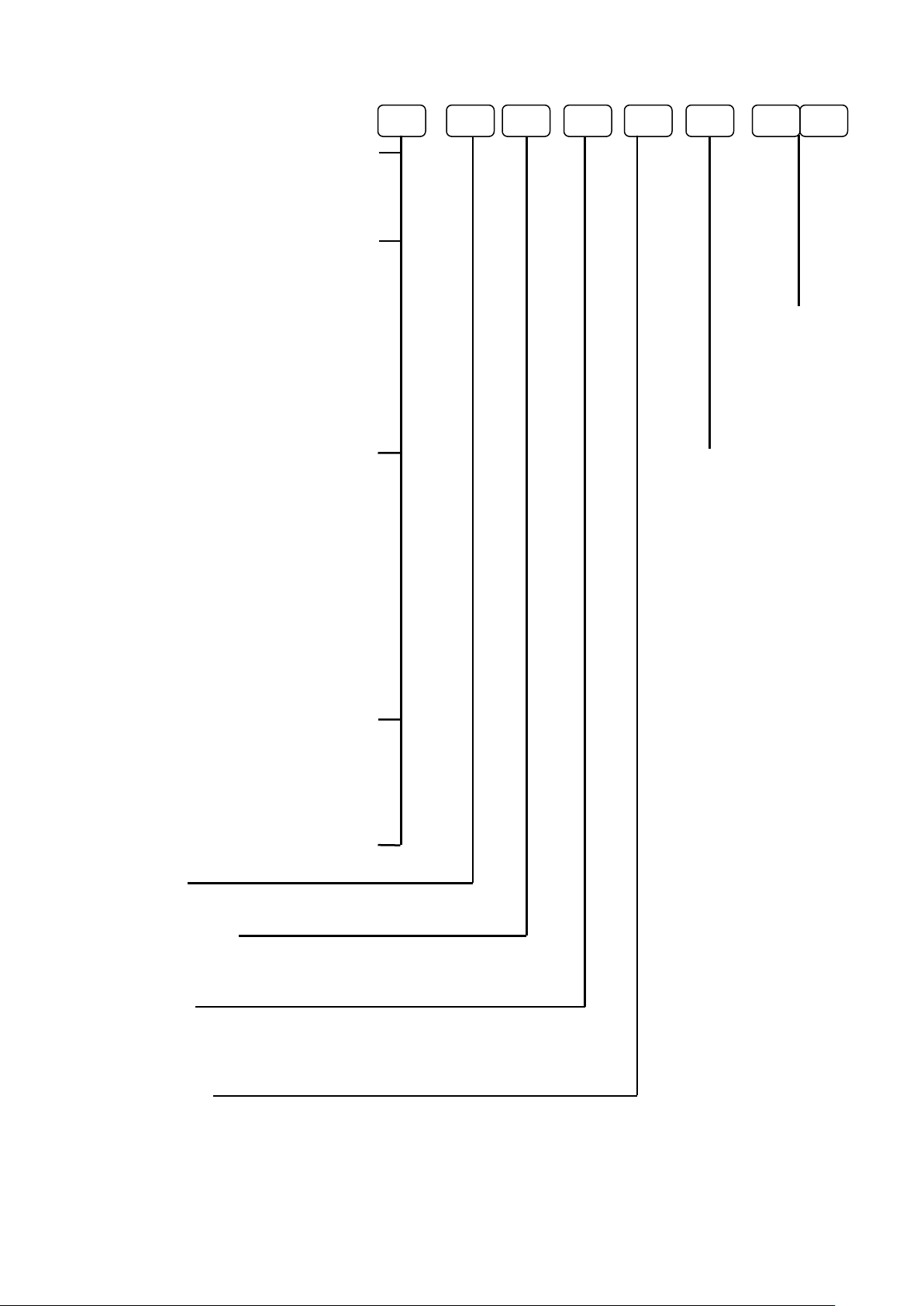
Page 21 of 479
1.8.2 PR20 Ordering code
PR2003 (3 Analog Inputs)
Other Inputs and Outputs
0: none
6: 3 relays + 3 DI
C: 3 relays + 3 DI + 6 AO
PR2006 (6 Analog Inputs)
Other Inputs and Outputs
0: none
1: 6 Relays
3: 6 DI
5: 6 AO Special options
6: 3 relays + 3 DI (Select from the option in the next page)
7: 6 relays + 6 DI
A: 6 relays + 6 AO
B: 6 DI + 6 AO
C: 3 relays + 3 DI + 6 AO
D: 6 relays + 6 DI + 6 AO
PR2012 (12 Analog Inputs)
Other Inputs and Outputs Mounting types, Power Cord & Switch
0: none (Select from the option in the next page)
1: 6 Relays
2: 12 Relays
3: 6 DI
4: 12 DI
5: 6 AO
6: 3 relays + 3 DI
7: 6 relays + 6 DI
8: 9 relays + 3 DI
9: 3 relays + 9 DI
A: 6 relays + 6 AO
B: 6 DI + 6 AO
C: 3 relays + 3 DI + 6 AO
PR2018 (18 Analog Inputs)
Other Inputs and Outputs
0: none
1: 6 Relays
3: 6 DI
5: 6 AO
6: 3 relays + 3 DI
PR2024 (24 Analog Inputs)
Other Inputs and Outputs
0: none
Power
A: 90-250 VAC, 50/60 Hz
D: 11-36 VDC
Communication
0: standard Ethernet interface
1: Ethernet + RS-232
2: Ethernet + RS-422/485
Firmware
0: Standard Version with Mathematic Functions
1: Plus Version 1 with external channels, batch & FDA 21 CFR part 11
2: Plus Version 2 with editable custom display and Panel Studio software
3: Plus Version 3- includes Plus Version 1+2 above
PC Software
1: Free Basic Software of Historical Viewer and Configuration
2: Extensive software Data Acquisition Studio
(Real Time Viewer + Historical Viewer + Configuration)
Page 22

Page 22 of 479
Mounting types, Power Cord & Switch
0: panel mount, no power cord, no power switch
1: panel mount, no power cord, power switch
2: portable, UL & CSA power cord, power switch
3: portable, VDE power cord, power switch
4: portable, SAA power cord, power switch
5: portable, BS power cord, power switch
6: portable, no power cord, power switch
7: Panel mount, UL & CSA power cord, power switch
8: Panel mount, VDE power cord, power switch
9: Panel mount, SAA power cord, power switch
A: Panel mount, BS power cord, power switch
Special options
00: none
S1: 16G SD card
S2: 32G SD card
Note:
DI- Digital Input
AO- Analog Output
PID Process Control card can be purchased separately
Process control card cannot be chosen together with
5: 6AO,
A: 6 relays + 6AO
B: 6DI +6AO
C: 3 relays + 3DI + 6AO
D: 6 relays + 6DI + 6AO
Nor with 24 analog inputs
Page 23

Page 23 of 479
1.8.3 PR30 Ordering code
PR3006 (6 Analog Inputs) PR3012 (12 Analog Inputs)
PR3018 (18 Analog Inputs)
PR3024 (24 Analog Inputs)
PR3030 (30 Analog Inputs)
PR3036 (36 Analog Inputs)
PR3042 (42 Analog Inputs)
PR3030 (48 Analog Inputs)
Relay
0: none
1: 6 Relays
2: 12 Relays
3: 18 Relays
4: 24 Relays
Digital Inputs
0: none
1: 6 Channels
2: 12 Channels
3: 18 Channels
Analog Outputs
0: none
1: 6 Channels
2: 12 Channels
Power
A: 90-250 VAC, 50/60 Hz
D: 11-36 VDC (UL Certification Not available)
Communication
0: standard Ethernet interface
1: Ethernet + RS-232
2: Ethernet + RS-422/485
Firmware
0: Standard Version with Mathematic Functions
1: Plus Version 1 with external channels, batch & FDA 21 CFR part 11
2: Plus Version 2 with editable custom display and Panel Studio software
3: Plus Version 3- includes Plus Version 1+2 above
PC Software
1: Free Basic Software of Historical Viewer and Configuration
2: Extensive software Data Acquisition Studio
(Real Time Viewer + Historical Viewer + Configuration)
Mounting types, Power Cord & Switch
0: panel mount, no power cord, no power switch
1: panel mount, no power cord, power switch
2: portable, UL & CSA power cord, power switch
3: portable, VDE power cord, power switch
4: portable, SAA power cord, power switch
5: portable, BS power cord, power switch
6: portable, no power cord, power switch
7: Panel mount, UL & CSA power cord, power switch
8: Panel mount, VDE power cord, power switch
9: Panel mount, SAA power cord, power switch
A: Panel mount, BS power cord, power switch
Special options
00: none
S1: 16G SD card
S2: 32G SD card
Page 24
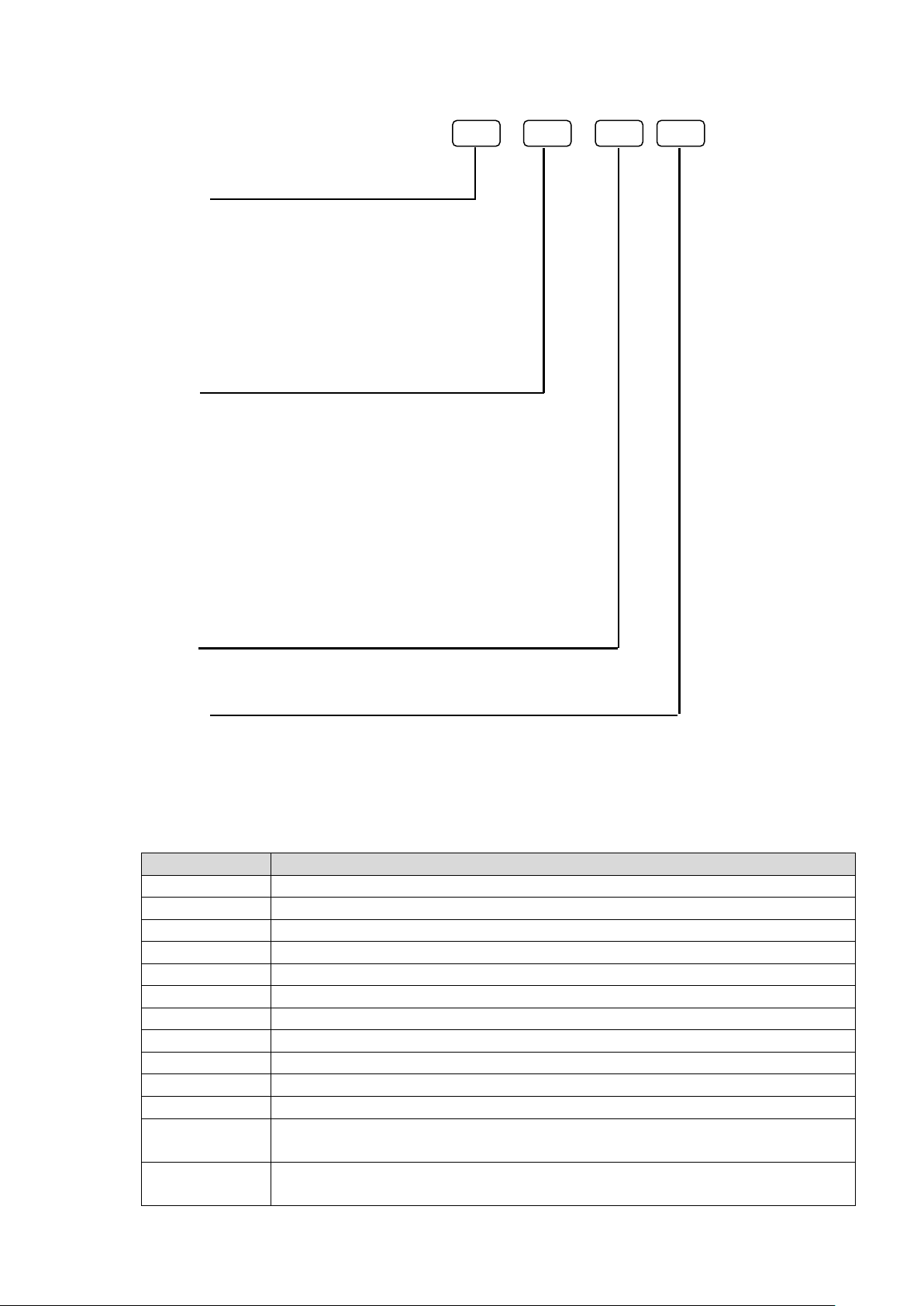
Page 24 of 479
1.8.4 PID Process Control Card PC201 Ordering code
PC201-
Output 1
0: None
1: Relay 2A/240VAC
2: Pulse voltage to drive SSR, 5V/30mA
3: Isolated 4-20mA/0-20mA (OM95-3)
4: Isolated 1-5V/0-5V (OM95-4)
5: Isolated 0-10V (OM95-5)
6: Triac output 1A/240VAC, SSR
C: Pulse voltage to drive SSR, 14V/40mA (OM94-7)
Output 2
0: None
1: Relay 2A/240VAC
2: Pulse voltage to drive SSR, 5V/30mA
3: Isolated 4-20mA/0-20mA (OM95-3)
4: Isolated 1-5V/0-5V (OM95-4)
5: Isolated 0-10V (OM95-5)
6: Triac output 1A/240VAC, SSR
7: Isolated 20VDC/25mA power supply (DC94-1)
8: Isolated 12VDC/40mA power supply (DC94-2)
9: Isolated 5VDC/80mA power supply (DC94-3)
C: Pulse voltage to drive SSR, 14V/40mA (OM94-7)
Alarm 1
0: None
1: Form C relay 2A/240VAC
Alarm 2
0: None
1: Form A relay 2A/240VAC
1.8.5 Accessories
Part no
Description
AI203
3-channel analog input card (TC, RTD, mA, V, mV)
AI206
6-channel analog input card (TC, RTD, mA, V, mV)
PC201
PID process control card
RO206
6-channel relay output card
DI206
6-channel digital input card
RD233
3-channel relay output and 3-channel digital input card
AO206
6-channel analog output card
IF232
RS-232 communication module for PR10 and PR20
IF485
RS-422/485 communication module for PR10 and PR20
IF232A
RS-232 communication module for PR30
IF485A
RS-422/485 communication module for PR30
PM201
90-250VAC 47-63Hz panel mount power supply board without power Switch for PR10
and PR20
PM202
90-250VAC 47-63Hz panel mount power supply board with power switch For PR10
and PR20
Page 25
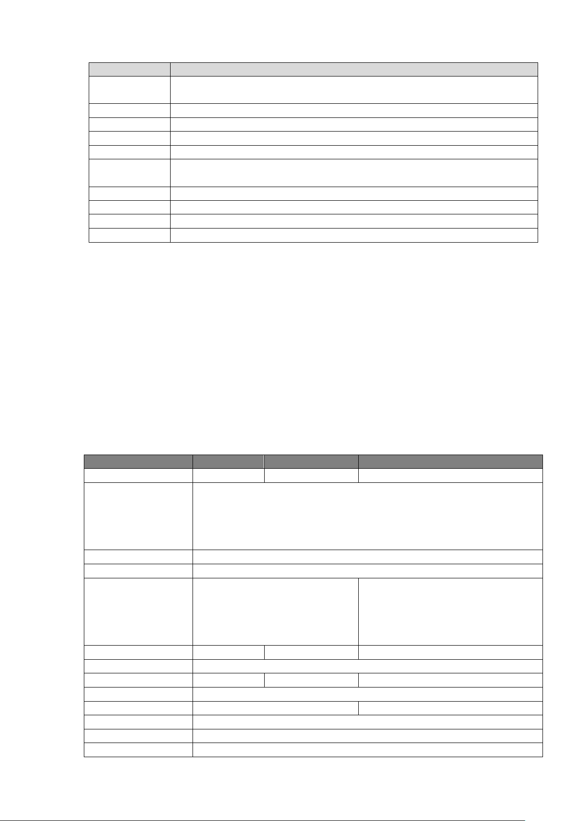
Page 25 of 479
Part no
Description
PM203
90-250VAC 47-63Hz portable power supply board with power switch for PR10 and
PR20
PM211
11-36VDC panel mount power supply board without power switch for PR10 and PR20
PM212
11-36VDC panel mount power supply board with power switch for PR10 and PR20
PM213
11-36VDC portable power supply board with power switch for PR10 and PR20
PM301
90-250VAC 47-63Hz panel mount power supply board without power Switch for PR30
PM302
90-250VAC 47-63Hz panel mount power supply board with power switch For PR30
PM303
90-250VAC 47-63Hz portable power supply board with power switch for PR30
PM311
11-36VDC panel mount power supply board without power switch for PR30
PM312
11-36VDC panel mount power supply board with power switch for PR30
PM313
11-36VDC portable power supply board with power switch for PR30
1-2 Accessories Ordering Code
Note:
❖ The rear slots of the recorder will accept certain Input or output cards only in any combination
based on selected model.
❖ The basic PC software is supplied free with the recorder. There is an additional charge for the
extensive Data Acquisition Software and communication ports of RS-232/422/485.
❖ The Ordering Code for various standard model Recorders with an AC supply and without any
additional options are as follows:
PR1003- 0A001000
PR2003- 0A001000
PR3006- 000A001000
1.9 Specifications
1.9.1 General Specifications
PR10
PR20
PR30
Number of Analog Input
3,6
3,6,12,18,24
6,12,18,24,30,36,42,48
Input Signals
Thermocouples: J, K, T, E, B, R, S, N, L, U, P, W5, W3, LR, A1, A2, A3, M
RTD: PT50, PT100, PT200, PT500,PT1000(α=0.00385), PT50,
PT100(α=0.00391), JPT50, JPT100, JPT200, JPT500, JPT1000(α=0.003916),
Cu10(α=0.00427),Cu50, Cu100(α=0.00426, 0.00428), Ni100, Ni200, Ni500,
Ni1000(α=0.00617), Current(mA),Voltage(Volts, mV)
Fastest Sampling rate
100msec/dot, Default setting : 1sec/dot
Calibration Correction
On-site Calibration possible or using Offset and Gain for correction
Power
90-250VAC, 47-63Hz, 52VA, 26W
maximum
11-36VDC, 26VA, 26W maximum
90-250VAC, 47-63Hz, 110VA, 62W
maximum,
11-36VDC, 62VA, 62W maximum (UL
Certification Not available)
Display Size
4.3”
5.6”
12.1”
Display Type
65K Colour, TFT Touch Screen
Display Resolution
480 x 272
640 x 480
1024 x 768
Backlight
LED
Display MTBF @25°C
30000 Hours
60000 Hours
CPU
ARM Cortex-A8, 1GHz
Internal Memory
256MB
External Storage
Max. Up to 32GB SD Card or USB Disk
Page 26
Page 26 of 479
PR10
PR20
PR30
SD Card Slot
Standard one slot at Front
USB Slot
Standard one USB slot in front and one USB slot in the rear
Pulse Input
Optional DI card support pulse Input up to 100Hz
PID Process Control
PID, Ramp & Dwell
Math Channel
Available by Standard version
External Channel,
Batch, Custom Display,
FDA 21 CFR Part 11
Available by plus versions
Multilingual
Convenient for local users by offering languages in Brazil Portuguese, Chinese
(Simplified, Traditional), Czech, Danish, Dutch, English, French, German, Greek,
Italian, Japanese, Korean, Polish, Portuguese, Russian, Spanish, Swedish, Thai,
Turkish. Other Languages negotiable.
Screen saver, Email
Available by Standard version
Ethernet
Standard Ethernet Port. Modbus TCP/IP (Server by default, Client available with
plus 1 version)
RS-232/422/485
Optional Rs232 or Optional RS422/485. Modbus RTU (Slave by default, Master
available with plus 1 version)
PC Software
Standard: Historical Viewer + Configuration
Optional: Extensive Software Data Acquisition Studio for real time monitoring
1.9.2 Analog Input Specifications (AI203 & AI206)
Channels: AI203 ~ 3 channels, AI206 ~ 6 channels
Resolution: 24 bits
Sampling Rate: 10 times/ second (100milliseconds)
Maximum Rating:
❖ RTD input ±20V
❖ Thermocouple and Voltage input ± 50V
❖ mA input ±10V
Temperature Effect:
❖ ±0.1uV ±15PPM of reading for all inputs except mA
❖ ±30PPM of reading for mA input
Sensor Lead Resistance Effect:
❖ Thermocouple: 0.32PPM of reading/Ω
❖ 3-wire RTD: 2.6˚C/Ω of resistance difference of two leads (Based on °C
measurement temperature for PT100)
❖ 2-wire RTD: 2.6˚C/Ω of resistance sum of two leads (Based on °C measurement
temperature for PT100)
Burn-out Current: 10uA
Common Mode Rejection Ratio (CMRR): 120dB
Normal Mode Rejection Ratio (NMRR): 55dB
Isolation Breakdown Voltage between channels: 1500VAC min.
Sensor Break Detection:
❖ Sensor opened for TC, RTD and mV inputs
❖ Below 1 mA for 4-20mA input
❖ Below 0.25V for 1-5V inputs
❖ Not available for other inputs
Sensor Break Responding Time:
❖ Within 1 seconds for TC, RTD and mV inputs
❖ 0.1 second for 4-20 mA and 1-5V inputs
Page 27
Page 27 of 479
Input Characteristics:
Type
Range
Accuracy at 25 ˚C
Input Impedance
J
-120 ~ 1000 ˚C (-184 ~ 1832 ˚F)
±1 ˚C
3.12MΩ
K
-200 ~ 1370 ˚C (-328 ~ 2498 ˚F)
±1 ˚C
3.12MΩ
T
-250 ~ 400˚C (-418 ~ 752˚F)
±1 ˚C
3.12MΩ
E
-100 ~ 900 ˚C (-148 ~ 1652 ˚F)
±1 ˚C
3.12MΩ
B
0 ~ 1820 ˚C (32 ~ 3308 ˚F)
±2˚C (200 ~ 1820˚C)
3.12MΩ
R
0 ~ 1768 ˚C (32 ~ 3214 ˚F)
±2 ˚C
3.12MΩ
S
0 ~ 1768 ˚C (32 ~ 3214 ˚F)
±2 ˚C
3.12MΩ
N
-250 ~ 1300 ˚C (-418 ~ 2372 ˚F)
±1 ˚C
3.12MΩ
L
-200 ~ 900 ˚C (-328 ~ 1652 ˚F)
±1 ˚C
3.12MΩ
U
-200 ~ 600˚C (-328 ~ 1112 ˚F)
±1 ˚C
3.12MΩ
P
0 ~ 1395 ˚C (32~2543 ˚F)
±1 ˚C
3.12MΩ
W5 or C
0 ~ 2315 ˚C (32 ~ 4199˚F)
±1 ˚C
3.12MΩ
W3
0 ~ 2315˚C (32 ~ 4199 ˚F)
±1 ˚C
3.12MΩ
LR
-200 ~ 800 ˚C (-328 ~ 1472 ˚F)
±1 ˚C
3.12MΩ
A1
0 ~ 2500 ˚C (-32 ~ 4532 ˚F)
±1 ˚C
3.12MΩ
A2
0 ~ 1800 ˚C (-32 ~ 3272 ˚F)
±1 ˚C
3.12MΩ
A3
0 ~ 1800 ˚C (-32 ~ 3272 ˚F)
±1 ˚C
3.12MΩ
M
-200 ~ 100 ˚C (-328 ~ 212 ˚F)
±1 ˚C
3.12MΩ
PT50 (α = 0.00385)
-200 ~ 850 ˚C (-328 ~ 1562 ˚F)
±0.4 ˚C
2.0KΩ
PT100 (α = 0.00385)
-200 ~ 850 ˚C (-328~ 1562 ˚F)
±0.4 ˚C
2.0KΩ
PT200 (α = 0.00385)
-200 ~ 850 ˚C (-328 ~ 1562 ˚F)
±0.4 ˚C
2.0KΩ
PT500 (α = 0.00385)
-200 ~ 850 ˚C (-328 ~ 1562 ˚F)
±0.4 ˚C
2.0KΩ
Page 28
Page 28 of 479
Type
Range
Accuracy at 25 ˚C
Input Impedance
PT1000 (α = 0.00385)
-200 ~ 350 ˚C (-328 ~ 662 ˚F)
±0.4 ˚C
2.0KΩ
PT50 (α = 0.00391)
-200 ~ 850 ˚C (-328 ~ 1562 ˚F)
±0.4 ˚C
2.0KΩ
PT100 (α = 0.00391)
-200 ~ 850 ˚C (-328 ~ 1562 ˚F)
±0.4 ˚C
2.0KΩ
JPT50 (α = 0.003916)
-200 ~ 600 ˚C (-328 ~ 1112 ˚F)
±0.4 ˚C
2.0KΩ
JPT100 (α = 0.003916)
-200 ~ 600 ˚C (-328 ~ 1112 ˚F)
±0.4 ˚C
2.0KΩ
JPT200 (α = 0.003916)
-200 ~ 600 ˚C (-328 ~ 1112 ˚F)
±0.4 ˚C
2.0KΩ
JPT500 (α = 0.003916)
-200 ~ 600 ˚C (-328 ~ 1112 ˚F)
±0.4 ˚C
2.0KΩ
JPT1000 (α = 0.003916)
-200 ~350 ˚C (-328 ~ 662 ˚F)
±0.4 ˚C
2.0KΩ
Cu50 (α = 0.00426)
-50 ~ 200 ˚C (-58 ~392 ˚F)
±0.4 ˚C
2.0KΩ
Cu100 (α = 0.00426)
-50 ~ 200 ˚C (-58 ~392 ˚F)
±0.4 ˚C
2.0KΩ
Cu50 (α = 0.00428)
-180 ~ 200 ˚C (-292 ~392 ˚F)
±0.4 ˚C
2.0KΩ
Cu100 (α = 0.00428)
-180 ~ 200 ˚C (-292 ~392 ˚F)
±0.4 ˚C
2.0KΩ
Ni100 (α = 0.00617)
-60 ~ 180 ˚C (-76 ~356 ˚F)
±0.4 ˚C
2.0KΩ
Ni200 (α = 0.00617)
-60 ~ 180 ˚C (-76 ~356 ˚F)
±0.4 ˚C
2.0KΩ
Ni500 (α = 0.00617)
-60 ~ 180 ˚C (-76 ~356 ˚F)
±0.4 ˚C
2.0KΩ
Ni1000 (α = 0.00617)
-60 ~ 180 ˚C (-76 ~356 ˚F)
±0.4 ˚C
2.0KΩ
Cu10 (α = 0.00427)
-200 ~ 260 ˚C (-328 ~500 ˚F)
±0.1 ˚C
2.0KΩ
±20mA
-26 ~ 26mA
±0.05%
75Ω
±60mV
-122 ~ 122mV
±0.05%
3.12MΩ
±200mV
-243 ~ 243mV
±0.05%
3.12MΩ
±1V
-1.58 ~ 1.58mV
±0.05%
3.12MΩ
±2V
-3.16 ~ 3.16mV
±0.05%
3.12MΩ
±6V
-6.32 ~ 6.32V
±0.05%
3.12MΩ
±20V
-25.3 ~ 25.3V
±0.05%
3.12MΩ
±50V
-50.6 ~ 50.6V
±0.05%
3.12MΩ
0.4 ~ 2V
-3.16 ~ 3.16V
±0.05%
3.12MΩ
1 ~ 5V
-6.32 ~ 6.32V
±0.05%
3.12MΩ
Page 29

Page 29 of 479
1.9.3 Digital Input Specifications (DI206 & RD233) Channels:
DI206: 6 Channels per card,
RD233: 3 Channels per card
Logic Low: -5V minimum, 0.8V maximum
Logic High: 3.5V minimum, 24V maximum
External pull-down Resistance: 1KΩ maximum
External pull-up Resistance: 1.5MΩ minimum
1.9.4 Relay Output Specifications (RO206 & RD206) Channels:
RO206: 6 Channels per card,
RD233: 3 Channels per card
Contact Form: N.O. & N.C. (Form C)
Relay Rating: 5A/240 VAC, life cycles 200,000 for resistive load
1.9.5 Analog Output Specifications (AO206) Channels: 6 Channels per card
Output signal: 4-20mA, 0-20mA, 0-5V, 1-5V, 0-10V
Resolution: 16 bits
Accuracy: ±0.05% of Span ±0.0025% /˚C
Load Resistance: 0-500Ω (current), 10KΩ minimum (voltage)
Output Regulation: 0.01% for full load change
Output Setting Time: 0.1 second (stable to 99.9%)
Isolation Breakdown Voltage: 1500VAC at 50/60Hz for 1 minute
Integral Linearity Error: ±0.005% of Span
Temperature Effect: ±0.0025% of Span /˚C
Note:
There are DIP switches available on the AO card to select the output type and the default setting
is SET to Voltage output. For Current (mA) Output, SET 1to 5 (ON) and 6 to 8 (OFF). For more details refer
to Chapter 5.1.4
1.9.6 PID Process Control card Specifications
1.9.6.1 Input1 Resolution: 18 bits
Sampling Rate: 5 times / second
Maximum Rating: -2 VDC minimum, 12 VDC maximum (1 minute for mA input)
Temperature Effect: 1.5uV/°C for all inputs except mA input, ±3.0uV/°C for mA input
Sensor Lead Resistance Effect:
❖ Thermocouple: 0.2uV/Ω
❖ 3-wire RTD: 2.6°C/Ω of resistance difference of two leads
❖ 2-wire RTD: 2.6° C/Ω of resistance sum of two leads
Burn-out Current: 200nA
Common Mode Rejection Ratio (CMRR): 120dB
Normal Mode Rejection Ratio (NMRR): 55dB
Sensor Break Detection: Sensor Open for Thermocouple, RTD and mV inputs
Sensor short for RTD input
Below 1 mA for 4-20 mA input
Below 0.25V for 1 - 5 V input
Not available for other inputs.
Page 30
Page 30 of 479
Sensor Break Responding Time:
❖ Within 4 seconds for TC, RTD and mV inputs
❖ 0.1 second for 4-20 mA and 1 - 5 V inputs
Input 1 Characteristics:
Type
Range
Accuracy @ 25°C
Input Impedance
J
-120°C to 1000°C (-184°F to 1832°F)
±2°C
2.2 MΩ
K
-200°C to 1370°C ( -328°F to 2498°F)
±2°C
2.2 MΩ
T
-250°C to 400°C ( -418°F to 752°F)
±2°C
2.2 MΩ
E
-100°C to 900°C ( -148°F to 1652°F)
±2°C
2.2 MΩ
B
0°C to 1800°C (32°F to 3272°F)
±2°C (200°C to 1800° C)
2.2 MΩ
R
0°C to 1767.8°C (32°F to 3214°F)
±2°C
2.2 MΩ
S
0°C to 1767.8°C (32°F to 3214°F)
±2°C
2.2 MΩ
N
-250°C to 1300°C (-418°F to 2372°F)
±2°C
2.2 MΩ
L
-200°C to 900°C (-328°F to 1652°F)
±2°C
2.2 MΩ
PT100(DIN)
-210°C to 700°C (-346°F to 1292°F)
±0.4°C
1.3KΩ
PT100(JIS)
-200°C to 600°C (-328°F to 1112°F)
±0.4°C
1.3Ω
mV
-8mV to 70mV
±0.05%
2.2 MΩ
mA
-3mA to 27mA
±0.05%
70.5Ω
V
-1.3V to 11.5V
±0.05%
302KΩ
1.9.6.2 Input2 Resolution: 18 bits
Sampling Rate: 5 times / second
Maximum Rating: -2 VDC minimum, 12 VDC maximum (1 minute for mA input)
Temperature Effect: 1.5uV/°C for all inputs except mA input, ±3.0uV/°C for mA input
Common Mode Rejection Ratio (CMRR): 120dB
Normal Mode Rejection Ratio (NMRR): 55dB
Sensor Break Detection:
❖ Below 1 mA for 4-20 mA input
❖ Below 0.25V for 1 - 5 V input
❖ Not available for other inputs
Sensor Break Responding Time: 0.5 Seconds
Input 2 Characteristics:
Type
Range
Accuracy @ 25°C
Input Impedance
CT94-1
0.0 to 50.0 A
±2% of Reading ±0.2A
302KΩ
mA
-3mA to 27mA
±0.05%
70.5Ω+(0.8V/Input Current)
V
-1.3V to 11.5V
±0.05%
302KΩ
1.9.6.3 Input3 (Event Input) Logic Low: -10V minimum, 0.8V maximum
Logic high: 2V minimum, 10V maximum
External pull-down Resistance: 400 KΩ maximum
External pull-up Resistance: 1.5 MΩ minimum
Functions:
Select second set point and/or PID, Reset alarm 1 and/or alarm 2, Disable output 1 and/or output
2, Remote lockout.
Page 31
Page 31 of 479
1.9.6.4 Output1/Output2
1. Relay Rating:
2A/240 VAC, life cycles 200,000 for Resistive load
2. Pulsed Voltage:
Source Voltage 5V, current limiting resistance 66Ω
3. Linear Output:
Resolution: 15 bits
Output Regulation: 0.01 % for full load change
Output Settling Time: 0.1 sec. (stable to 99.9 %)
Isolation Breakdown Voltage: 1000 VAC
Temperature Effect: ±0.0025 % of SPAN /°C
Linear Output Characteristics:
Type
Zero Tolerance
Span Tolerance
Load Capacity
4 to 20mA
3.8-4 mA
20-21 mA
500 Ω max
0 to 20mA
0 mA
20-21 mA
500 Ω max
0 to 5V
0 V
5 -5.25 V
10KΩ min
1 to 5V
0.95 to 1V
5 -5.25 V
10KΩ min
0 to 10V
0 V
10 - 10.5 V
10KΩ min
4. Triac (SSR) Output:
Rating: 1A / 240 VAC
Inrush Current: 20A for 1 cycle
Min. Load Current: 50 mA RMS
Max. Off-state Leakage: 3 mA RMS
Max. On-state Voltage: 1.5 V RMS
Insulation Resistance: 1000 MΩ minimum at 500 VDC
Dielectric Strength: 2500 VAC for 1 minute
SSR Output Characteristics:
Type
Tolerance
Maximum
Output
Current
Ripple
Voltage
Isolation
Barrier
20V
±0.5 V
25 mA
0.2 Vp-p
500 VAC
12V
±0.3 V
40 mA
0.1 Vp-p
500 VAC
5V
±0.15 V
80 mA
0.05 Vp-p
500 VAC
1.9.6.5 Alarm 1/ Alarm 2 Alarm 1 Relay: Form C, Max. Rating 2A/240VAC, life cycles 200,000 for resistive load
Alarm 2 Relay: Form C, Max. Rating 2A/240VAC, life cycles 200,000 for resistive load
Alarm Mode: Normal, Latching, Hold, Latching / Hold
Dwell Timer: 0 - 6553.5 minutes
Alarm Functions:
Dwell timer, Deviation High / Low Alarm, Deviation Band High / Low Alarm, PV1 High /
Low Alarm, PV2 High / Low Alarm, PV1 or PV2 High / Low Alarm, PV1-PV2 High / Low
Alarm, Loop Break Alarm, Sensor Break Alarm
1.9.6.6 Control Mode Output 1: Reverse (heating) or direct (cooling) action
Output 2: PID cooling control, cooling P band 1~255% of PB
Page 32

Page 32 of 479
ON-OFF: 0.1 - 100.0(°F) hysteresis control (P band = 0)
P or PD: 0 - 100.0 % offset adjustment
PID:
Fuzzy logic modified Proportional band 0.1 ~ 900.0°F,
Integral time: 0 - 1000 Seconds,
Derivative time 0 - 360.0 seconds
Cycle Time: 0.1 - 100.0 seconds
Manual Control: Heat (MV1) and Cool (MV2)
Auto-tuning: (MV2) Cold start and warm start
Self-tuning: Select None and YES
Failure Mode: Auto-transfer to manual mode while sensor break or A-D converter damage
Sleep Mode: Enable or Disable
Ramping Control: 0 - 900.0°F/minute or 0 - 900.0°F/hour ramp rate
Power Limit: 0 - 100 % output 1 and output 2
Pump / Pressure Control: Sophisticated functions provided
Remote Set Point: Programmable range for voltage or current input
Differential Control: Control PV1-PV2 at set point
1.9.6.7 Profiler Number of Profiles: 50
Number of Segments per Profile: 32
Note: Total Segments are limited to 1000 Segments
1.9.6.8 Digital Filter Function: First Order
Time Constant: 0, 0.2, 0.5, 1, 2, 5, 10, 20, 30, 60 seconds programmable
1.9.7 COMM Module (IF232 and IF485) Specifications Interface: RS-232 (IF232-one unit) or RS-485 or RS-422 (IF485- up to 247 units)
Protocol: Modbus Protocol RTU mode
Address: 1-247
Baud Rate: 9.6 ~ 115.2 Kbits/sec.
Data Length: 7 or 8 bits
Parity Bit: None, Even or Odd
Stop Bit: 1 or 2 bits
1.9.8 Standard Ethernet Communication Protocol: Modbus TCP/IP, 10/100 Base T
Ports: AUI (Attachment Unit Interface) and RJ-45, Auto- detect capability
1.9.9 Real-time Clock
Item
Description
Make
Seiko Instruments
Model
MS621-fl11e
Rating
3V,4mAH
Typical Life Time
10 Years
Buffer Period
6 Months
Type
Rechargeable
Accuracy
Maximum ± 2Seconds/Day
Page 33
Page 33 of 479
1.9.9.1 Real time Clock accuracy vs Temperature inside of the housing
Temperature Inside Housing
Typical Error / Month
10°C ~ 40 °C
18 Seconds
0°C or 50 °C
52 Seconds
-10°C or 60°C
107 Seconds
1.9.10 Environmental & Physical Specifications Operating Temperature: 0 ~ 50 ˚C
Storage Temperature: -30 ~ 70 ˚C
Humidity: 20 to 90% RH (non-condensing)
Maximum relative humidity 90% is for ambient temperature up to 38˚C decreasing linearly to
50% relative humidity at 50˚C
Altitude: 2000 M maximum
Insulation Resistance: 20 MΩ min. (at 500 VDC)
Dielectric Strength: 2300VAC, 50/60 Hz for 1 minute between power terminal and earth
Vibration Resistance: 10-55 Hz, 10m/ s² for 2 hours
Shock Resistance: 30m/ s² (3g) for operation, 20g for transportation
Operation Position: no inclined restriction
Dimensions: Panel Mount style: PR10/PR20:144(W) x 144(H) x 193mm (D)
PR30:288(W) x 288(H) x 194mm (D)
Standard Panel Cut-out: PR10/PR20:137 x 137mm
PR30:281 x 281mm
1.9.11 Approval Standards Safety:
UL61010C-1, CSA C22.2 No. 24-93
CE: EN61010-1 (IEC1010-1) over voltage category II, Pollution degree 2
Protective Class:
IP 65 front panel for indoor use
IP 20 housing and terminals
EMC:
Emission: EN61326-1 (EN55022 class A, EN61000-3-2, EN61000-3-3)
Immunity: EN61326-1 (EN61000-4-2, EN61000-4-3, EN61000-4-4,
EN61000-4-5, EN61000-4-6, EN61000-4-8, EN61000-4-11)
2. Installation and wiring
Sometimes dangerous voltages capable of causing death are present in this instrument. Before doing
installation or any troubleshooting procedures, the power to the equipment must be switched off and
isolated. Units suspected of being faulty must be disconnected and removed to a properly equipped
workshop for testing and repair. Component replacement and internal adjustments must be made by a
qualified maintenance person only.
To minimize the possibility of fire or shock hazards, do not expose this instrument to rain or excessive
moisture.
Do not use this instrument in areas under hazardous conditions such as excessive shock, vibration, dirt,
moisture, corrosive gases or oil. The ambient temperature of the area should not exceed the maximum
rating specified in the specification
Page 34
Page 34 of 479
Remove stains from this equipment using a soft, dry cloth. Do not use harsh chemicals, volatile
solvents such as thinner or strong detergents to clean the equipment in order to avoid deformation.
If the equipment is used in a manner not specified by the manufacturer, the protection provided by the
equipment may be impaired.
2.1 Unpacking
Upon receipt of the shipment, remove the recorder from the carton and inspect the unit for
shipping damage. If any damage is found, contact your local representative immediately. Note the model
number and serial number for future reference when corresponding with our service centre. The serial
number (S/N) is labelled on the box and the housing of the recorder.
The recorder is designed for indoor use only, and is not intended for use in any hazardous area.
It should be kept away from shock, vibration, and electromagnetic fields (such as variable frequency drives),
motors and transformers. It is intended to operate under the following environmental conditions.
Environmental Parameter
Specification
Operating Temperature
0°C to 50 °C
Humidity
20% to 90% RH(Non-condensing)
Altitude
2000 M Maximum
Pollution Degree Level II
IEC1010-1(EN61010-1)
Power
90 ~ 250 VAC, 50/60 Hz or 11-36VDC
2.2 Dimensions
2.2.1 Panel mounting style
2.2.1.1 PR10
Page 35
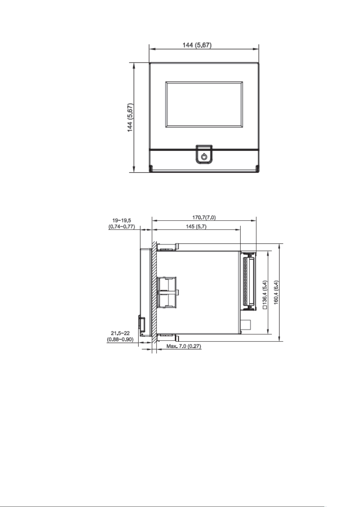
Page 35 of 479
2-1 PR10 Front Side
2-2 PR10 Right Side
Page 36
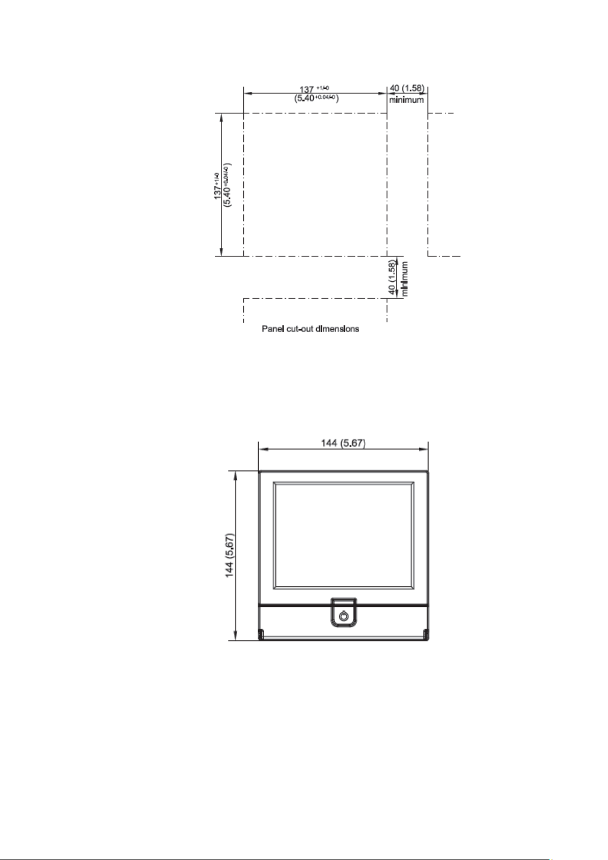
Page 36 of 479
2-3 PR10 Panel Cut-out Dimensions
2.2.1.2 PR20
2-4 PR20 Front Side
Page 37
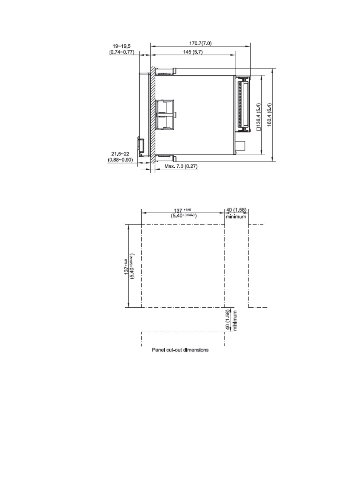
Page 37 of 479
2-5 PR20 Right Side
2-6 PR20 Panel Cut-out Dimensions
Page 38
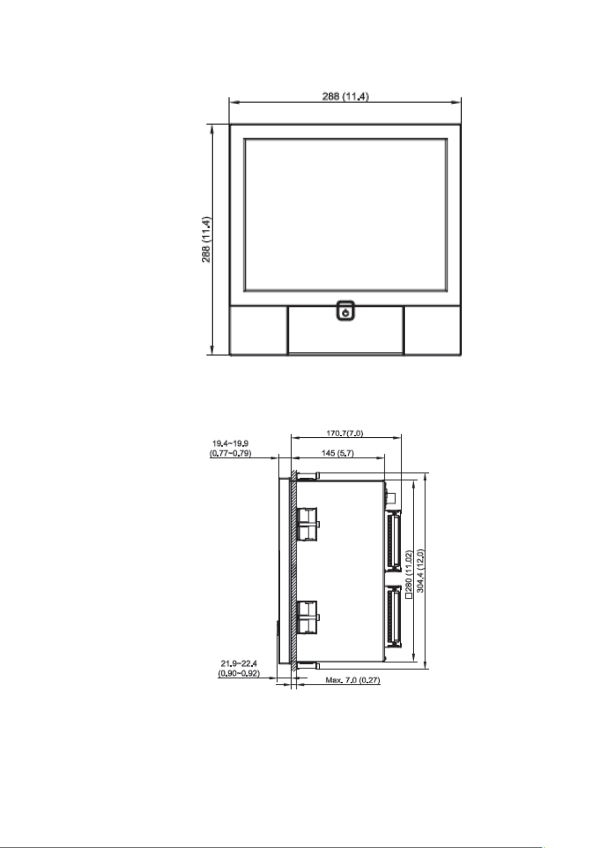
Page 38 of 479
2.2.1.3 PR30
2-7 PR30 Front Side
2-8 PR30 Right Side
Page 39
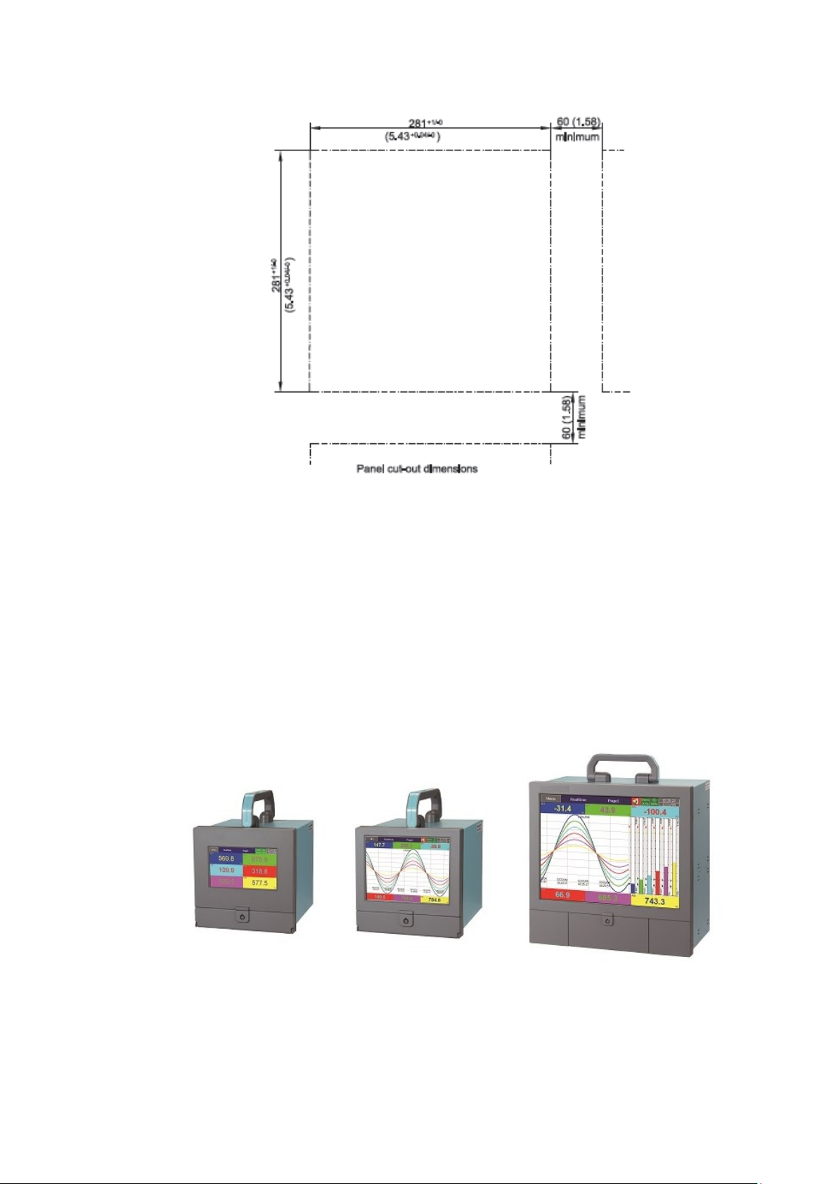
Page 39 of 479
2-9 PR30 Cut-out Dimensions
Note:
❖ Do not over tighten mounting clamp screws that could result in distortion of the case.
❖ There is no mounting angle restriction.
❖ The mounting torque used for 4 sides of the housing should be 2.0 KgF-cm and not more than
2.5 KgF-cm
2.2.2 Portable styles
Page 40
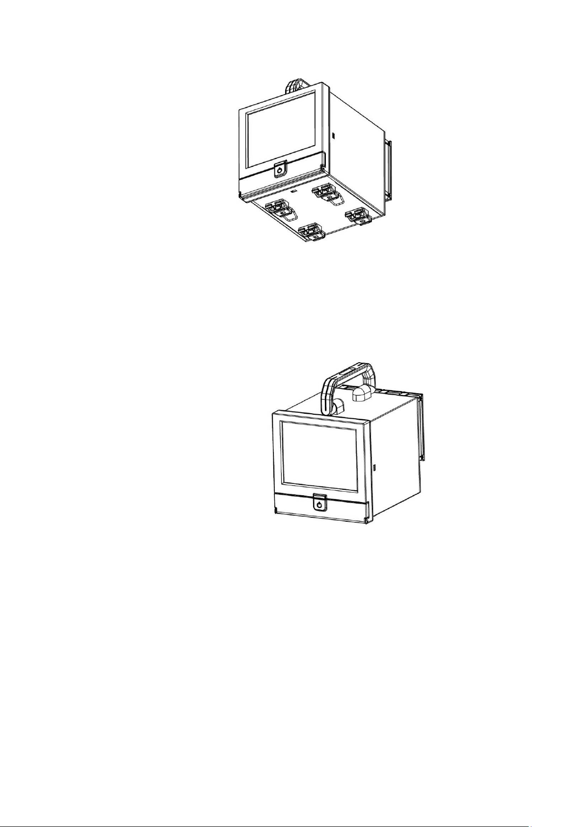
Page 40 of 479
2.2.2.1 Bottom Side View of PR20 & PR10
2-10 PR10 & PR20 Portable Type Bottom Side View
2.2.2.2 Front Side View of PR20 & PR10
2-11 PR10 & PR20 Portable Type Front Side View
Page 41
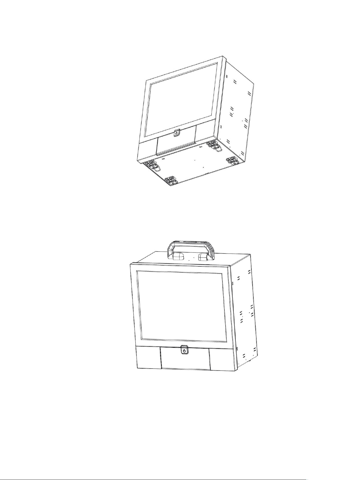
Page 41 of 479
2.2.2.3 Bottom Side View of PR30
2-12 PR30 Portable Type Bottom Side View
2.2.2.4 Front Side View of PR30
2-13 PR30 Portable Type Front Side View
Page 42
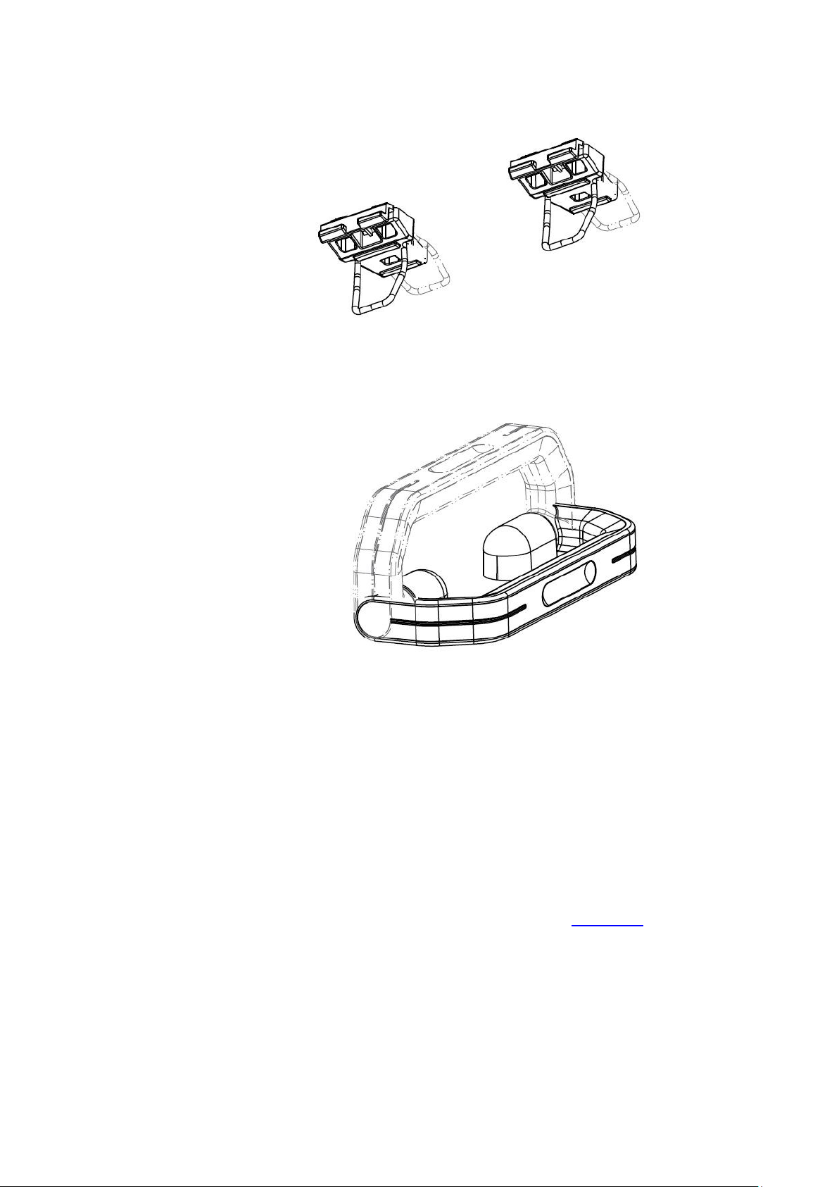
Page 42 of 479
2.2.2.5 Bottom Stand Clips
2-14 Portable Type Bottom Stand Clips
2.2.2.6 Top Holding Handle
2-15 Portable Type Top Holding Handle
2.3 Input and Output Configuration
The Input and Output cards needs to be inserted to the rear slots or removed from the rear slots
at the Power OFF condition. Failure to do so may cause damage to the module or device or both. The
Device will automatically detect the cards at Power ON, once it is inserted in to the rear slots.
2.3.1 Analog Input Card (AI206 & AI203) AI206 and AI203 are analog input cards with 3 and 6 channels respectively. Each card includes
universal inputs of TC (J, K, T, E, B, R, S, N, L, U, P, W5, W3, LR, A1, A2, A3, and M), RTD, mV, mA, V.
The accepted input types and sensor range for analog input are listed in Chapter 1.9. Plug the AI card into
the rear slot then power on. The recorder will automatically detect the card and display the specific input
type and its location in a specific slot in System Information mode while doing the configuration.
The configuration Menu can be reached by pressing Menu and then pressing more and then
pressing Config key. It will display a tree type configuration layout for easy user configuration. By using
Up/Down Key and Enter Key, AI configuration window can be reached. In this window the user can
configure the AI parameters. The user can select the desired input type and other parameters for analog
input in this window.
Page 43
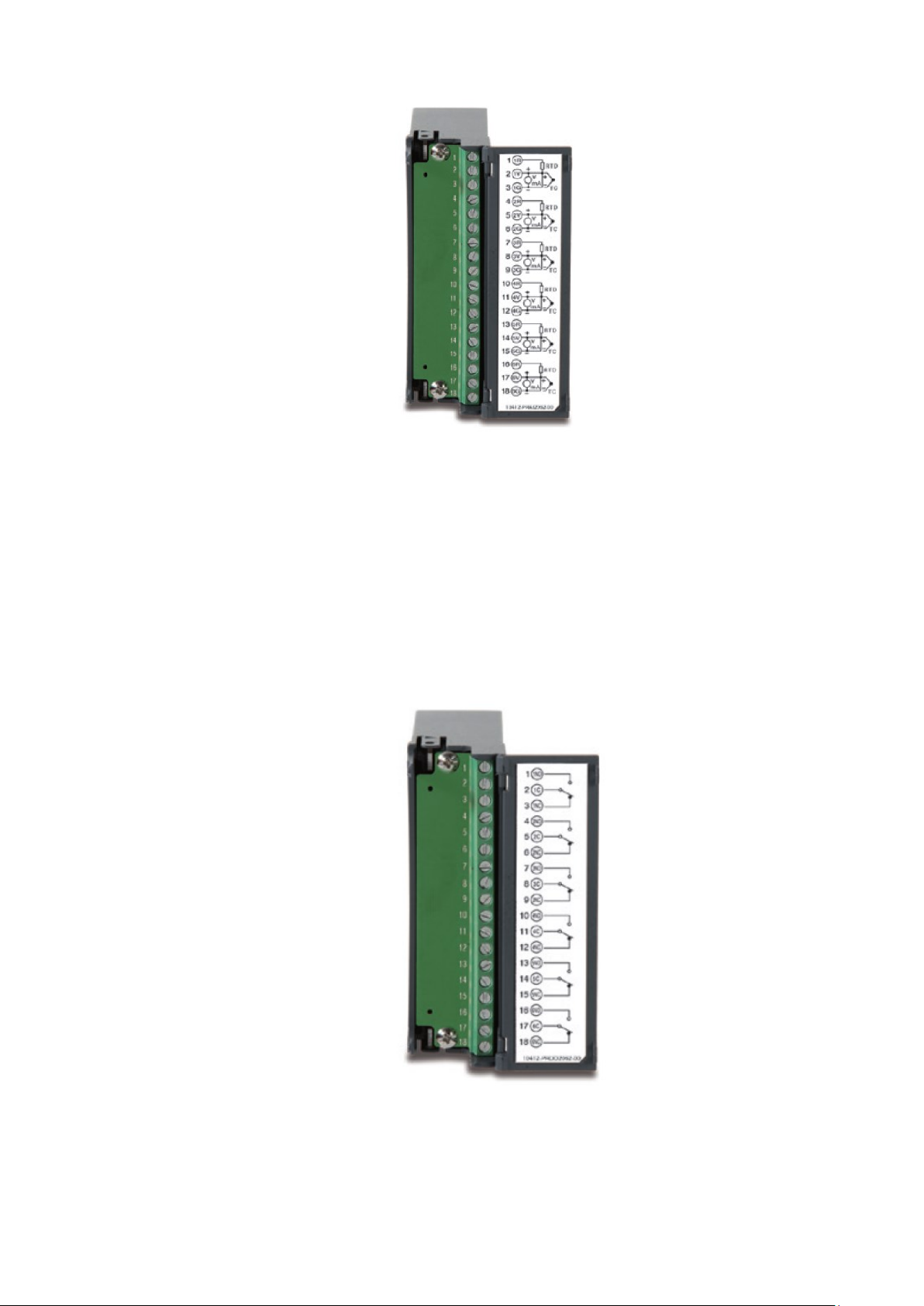
Page 43 of 479
2.3.2 Relay Output card (RO206)
The relay output card RO206 includes 6 relays rated 5 Amp/240 VAC each. Plug the card into a
rear slot and power on the recorder. The recorder will automatically detect the card and display the output
type and its location in a specific slot in System Info mode while doing the configuration.
The configuration Menu can be reached by pressing Menu and then pressing more and then
pressing Config key. It will display a tree type configuration layout for easy user configuration. By using
Up/Down Key and Enter Key, DO configuration window can be reached. In this window the user can
configure the DO parameters. The user can select the desired output type and other parameters for Relay
output in this window. The item "Reverse" is to reverse the output status.
Page 44
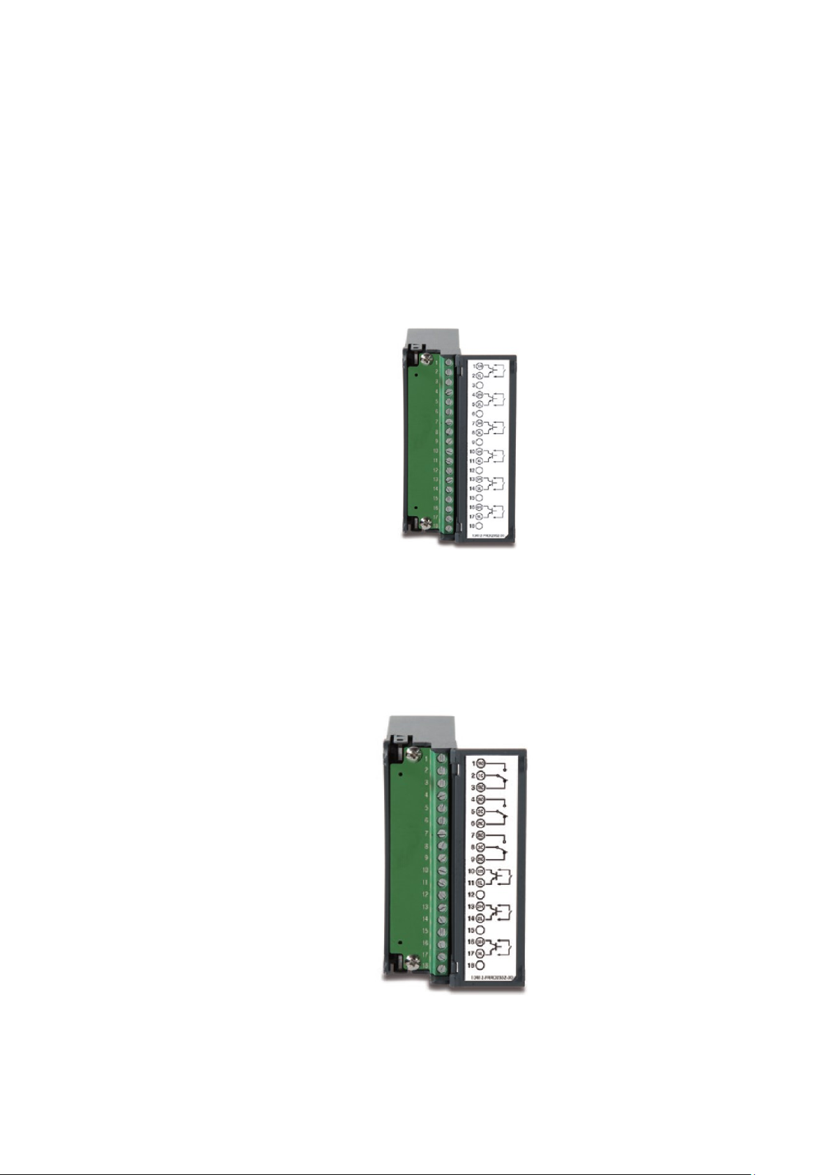
Page 44 of 479
2.3.3 Digital Input card (DI206)
This card includes 6 channels of event inputs. As above, plug the card into rear slot and power
on the recorder. The recorder will automatically detect it, and then display the input type and its location in a
specific slot in System Information mode while doing the configuration.
The configuration Menu can be reached by pressing Menu and then pressing more and then
pressing Config key. It will display a tree type configuration layout for easy user configuration. By using
Up/Down Key and Enter Key, DI configuration window can be reached. In this window the user can
configure the DI parameters. The user can select the desired input type and other parameters for digital
input in this window. The item "Type" is for the user to decide if this channel will have a logic level or Pulse
Counter input. If you select Pulse Counter, the item "Frequency" will appear for you to select input
frequency (100Hz). The item "Events" can be added to do further control.
2.3.4 Combination Digital Input and Output card (RD233)
This card includes 3 relays rated 5 Amp/240VAC each and 3 Channels of Digital Inputs. As
above, plug the card into rear slot and power on the recorder. The recorder will automatically detect it, and
then display the input type and the output type on its location in a specific slot in System Information mode
while doing the configuration. The first 3 channels are for relays (Terminal 1 to 9) and last 3 channels are for
Digital inputs (Terminals 10 to 18). The setup is similar to relay output card and digital input card.
Page 45
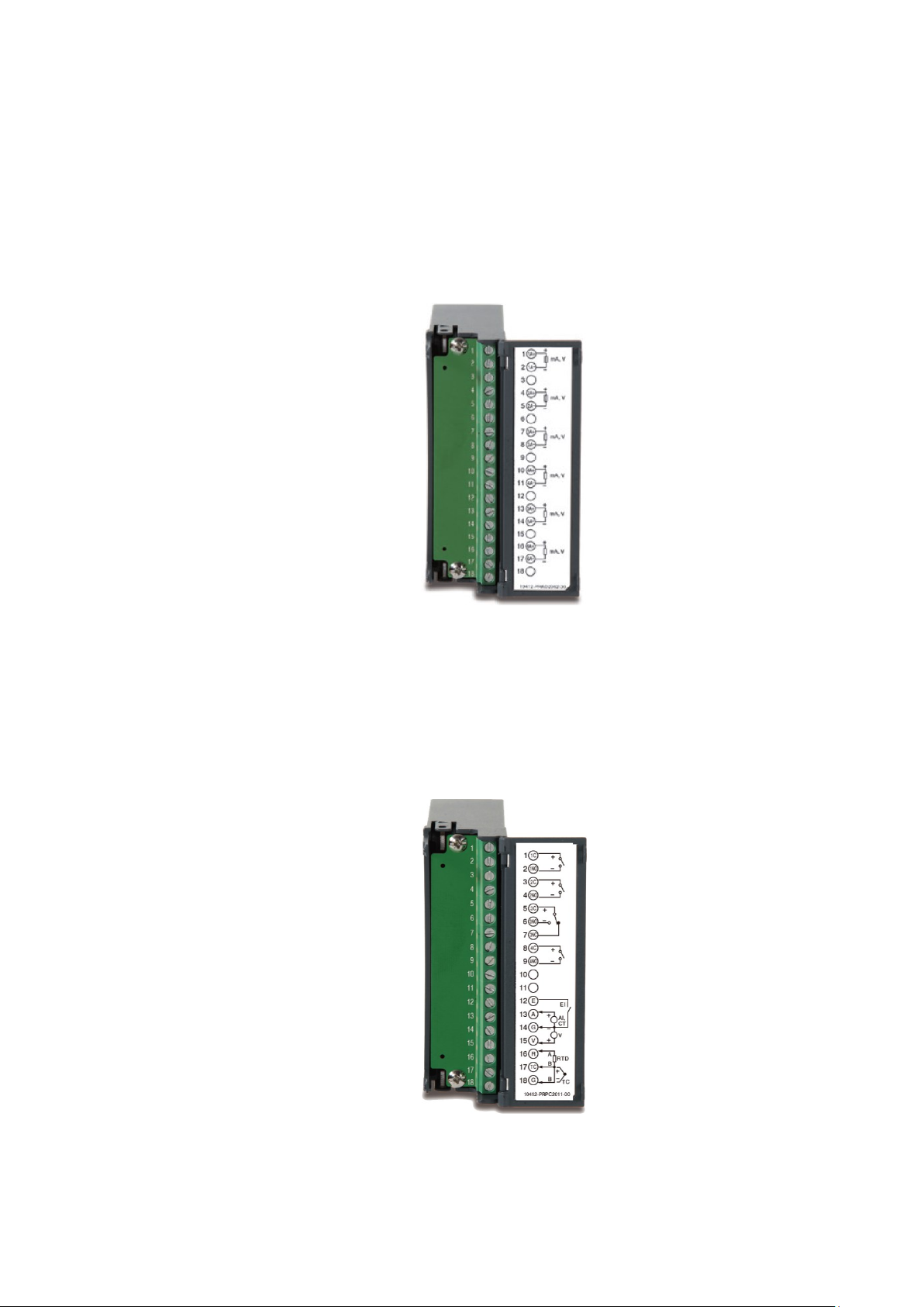
Page 45 of 479
2.3.5 Analog output cards (AO206)
These cards are 6-channel analog output cards. They are used to retransmit process values to
other devices like meters, controllers, etc. The configuration Menu can be reached by pressing Menu and
then pressing more and then pressing Config key. It will display a tree type configuration layout for easy
user configuration. By using Up/Down Key and Enter Key, AO configuration window can be reached. In this
window the user can configure the AO parameters. The user can select the desired output type and other
parameters for analog output in this window.
Note: There is dip switch on the AO206 card to select the current or voltage output for each
channel.
2.3.6 PID Process Control Module (PC201)
This is a single loop PID Control Module which consists of Universal Input. The Module output
can be configured by using the configuration Menu. The configuration Menu can be reached by pressing
Menu and then pressing more and then pressing Config key. It will display a tree type configuration layout
for easy user configuration. By using Up/Down Key and Enter Key, PID Controller and Profile configuration
window can be reached. In this window the user can configure the Controller parameters and profiles of PID
Control Module. The user can select the desired output type and other parameters for analog output in this
window.
Page 46
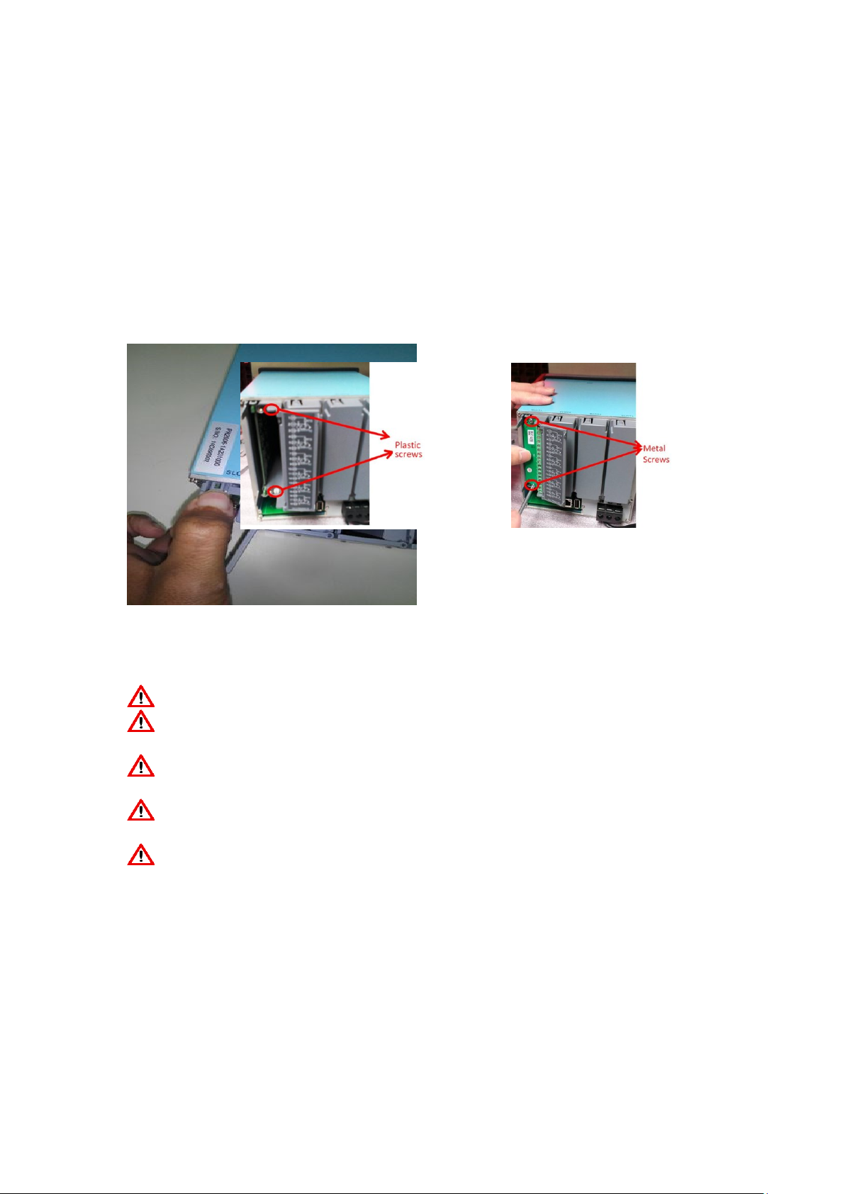
Page 46 of 479
Note:
❖ The IO Modules should not be removed or Inserted to the device when the Power is ON. This
should be carried out in the Power OFF Condition only.
❖ For removing the IO Modules, First remove the metal screws then remove the plastic screws, after
that press the lock on the top and bottom of the Card and pull to remove it. Failing to do so will
damage the IO Card. Please follow the Recorder user manual for more information.
❖ The Maximum Torque for the metal screw is 3Kg-cm (2.6in-lb) and the Maximum Torque for the
plastic screw is 0.8Kgf-cm (.7in-lb).
❖ Calibration should be carried out by a qualified Engineer with qualified equipment only.
❖ Thermocouple inputs requires 1 hour initial warm up time during initial setup.
❖ For some industries who prefer circular chart displays, PR30 can offer this Unique feature and set
the display speed for each page/circle in 30 minutes, 1, 2, 4, 8, 12 hours, 1, 2 days, or 1, 2, 4
weeks.
2.4 Wiring
2.4.1 Wiring Precautions
Care must be taken to ensure that the maximum voltage rating specified on the label is not exceeded.
For the panel-mount version, it is recommended that near an external fuse or an external switch rated
at 2A/250 VAC should be used.
Beware not to over tighten the terminals screws. The torque should not exceed 0.4 N-m (3.6 Lb-in or
4.0 Kg F-cm).
With the exception of the thermocouple wires, all wires should be stranded copper conductor with
maximum gauge of 18 AWG.
Connect a grounding conductor with 1.6mm diameter minimum to provide protective grounding prior to
turning on the equipment.
Page 47
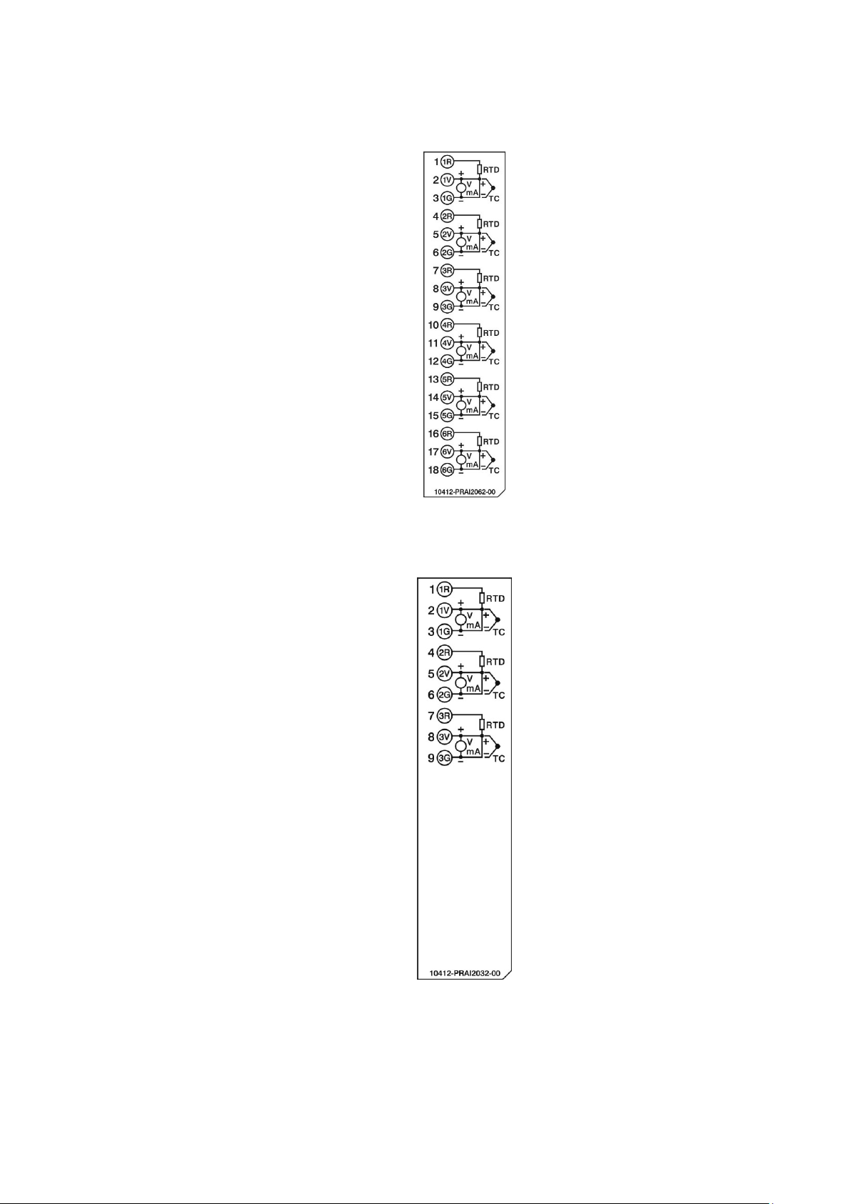
Page 47 of 479
2.4.2 Analog Input Wiring
2.4.2.1 AI206 wiring
2.4.2.2 AI203 Wiring
Page 48

Page 48 of 479
2.4.3 Relay Output Wiring
2.4.3.1 RO206
Page 49
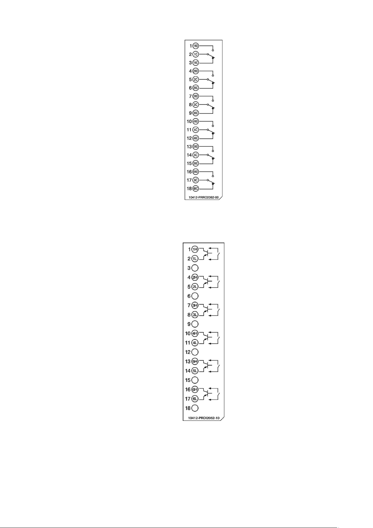
Page 49 of 479
2.4.4 Digital Input Wiring
2.4.4.1 DI206
Page 50
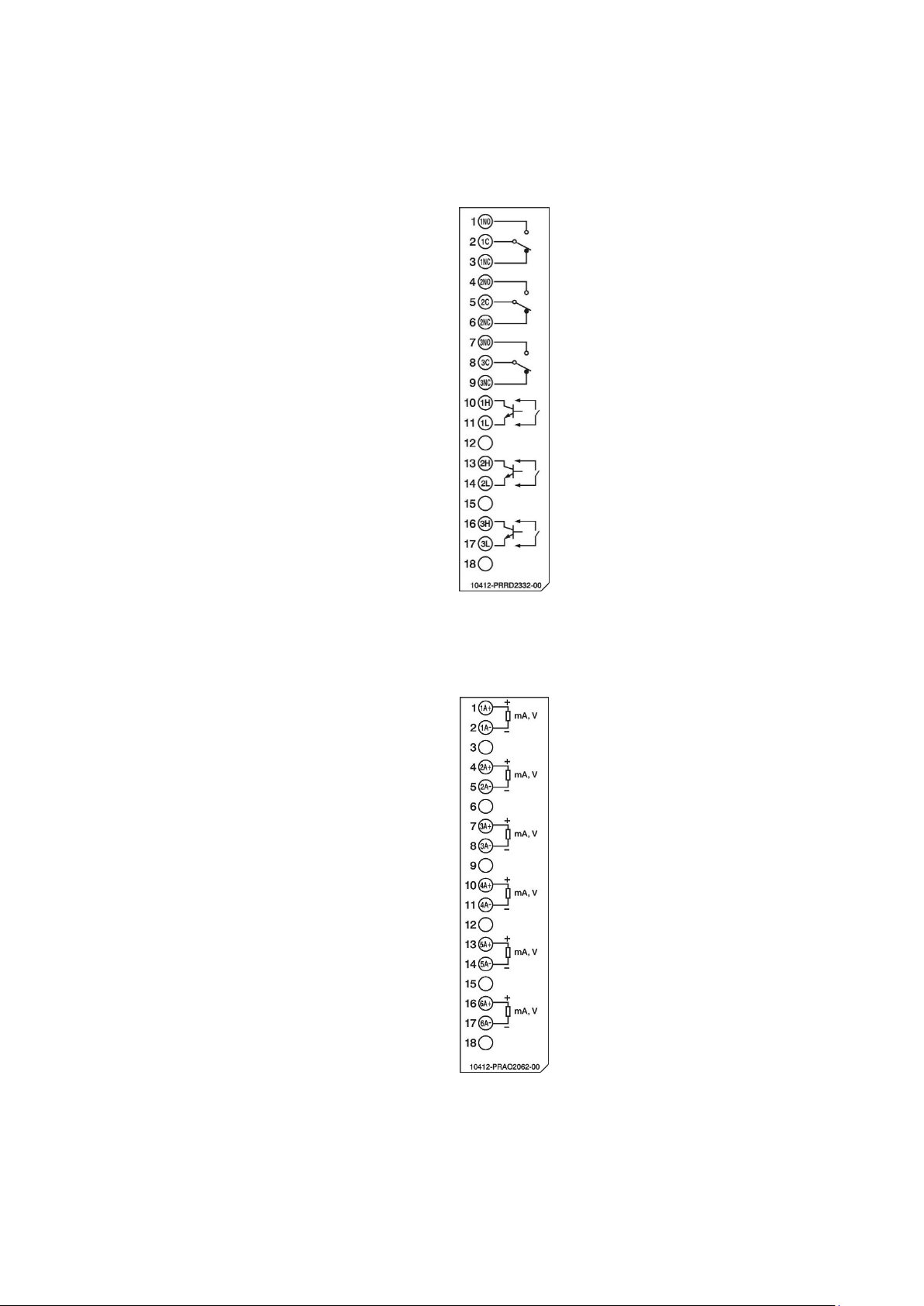
Page 50 of 479
2.4.5 Combination Relay Output and Digital Input Wiring
2.4.5.1 RD233
2.4.6 Analog Output Wiring
2.4.6.1 AO206
Page 51
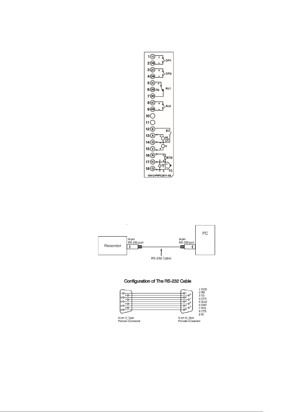
Page 51 of 479
2.4.7 PID Process Control Card Wiring
2.4.7.1 PC201
2.4.8 RS-232, RS-422, and RS-485 wiring
2.4.8.1 RS232 Wiring
Page 52
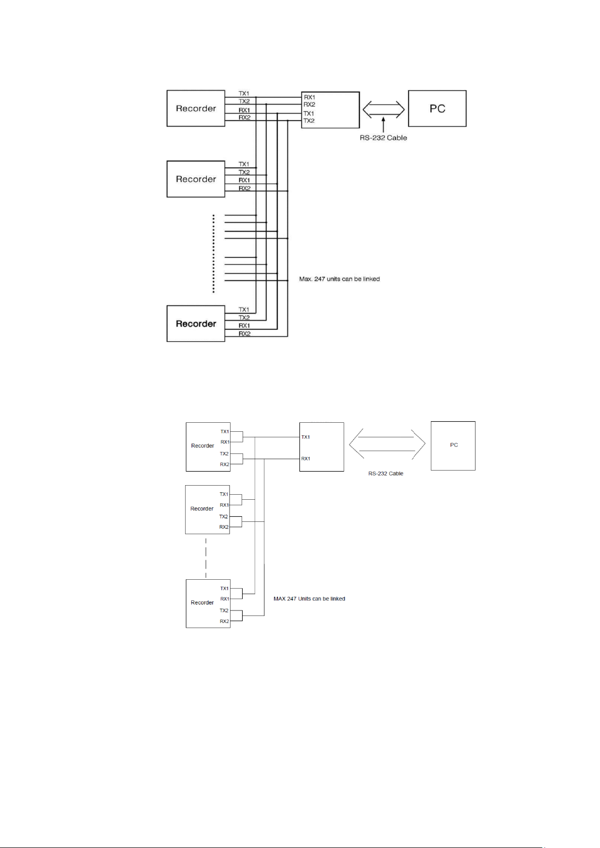
Page 52 of 479
2.4.8.2 RS422 Wiring
2.4.8.3 RS485 Wiring
2.5 External Memory Card
There are two types of external storage for the User to use in the recorder. One is the SD card
and other is USB memory. There are two slots for inserting USB memory, one in the front and other on the
rear side of the recorder. If bigger capacity USB memory is required, the user may buy it locally. The SD
card slot is in the front side. Please see the below figures for more information.
RS232 to RS422 Converter
RS232 to RS485 Converter
Page 53
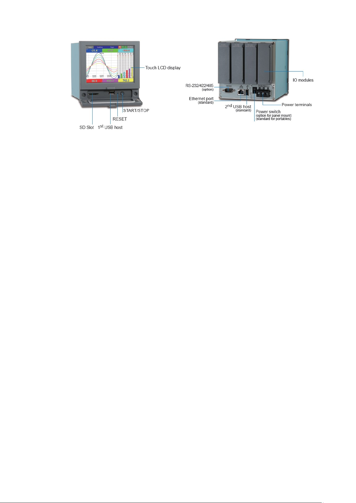
Page 53 of 479
Note
❖ The maximum capacity of external memory supported by recorder is 32GB. The external memory must be
formatted to FAT or FAT32.
❖ To read measured data and events on USB memory and SD card Memory, it is necessary to install either the
free basic software or the Extensive Data Acquisition software on PC first.
Page 54
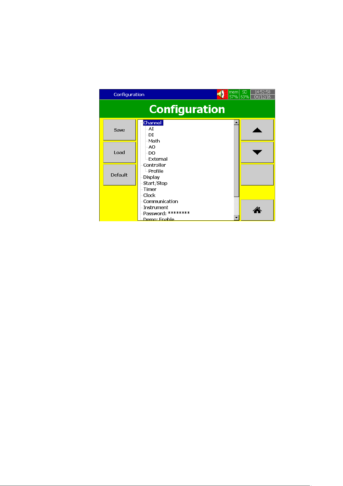
Page 54 of 479
3. BASIC FUNCTIONS OF RECORDERS
3.1 Configuration
The configuration of the recorder follows a tree type layout. This makes it easy for the users to
go through the different sub menus easily and do not miss any configuration.
3.2 Firmware
The PR series recorder has 4 different versions of firmware for the user to select as per the
application requirement.
1. Standard Firmware
2. Plus 1 Firmware
3. Plus 2 Firmware
4. Plus 3 Firmware
3.2.1 Standard Firmware
The standard version of firmware have Input and output configuration, Math functions (Counter,
Totalizer),PID Controller function with PID Process control card. This firmware does not include External
channels, Custom Edited Display, Batch, or FDA 21 CFR part11 functions.
3.2.2 Plus 1 Firmware
The plus 1 firmware have external channel, Batch, FDA 21CFR Part 11 functions along with the
functions available in standard version firmware. This firmware does not include custom display function.
3.2.3 Plus 2 Firmware
The plus 2 firmware version have custom display function similar to HMI along with the functions
available in standard version firmware. This firmware does not include external channel, Batch, FDA 21CFR
part11 functions.
3.2.4 Plus 3 Firmware
The plus 3 firmware have all the functions of standard, plus1, plus 2 version firmware.
Page 55
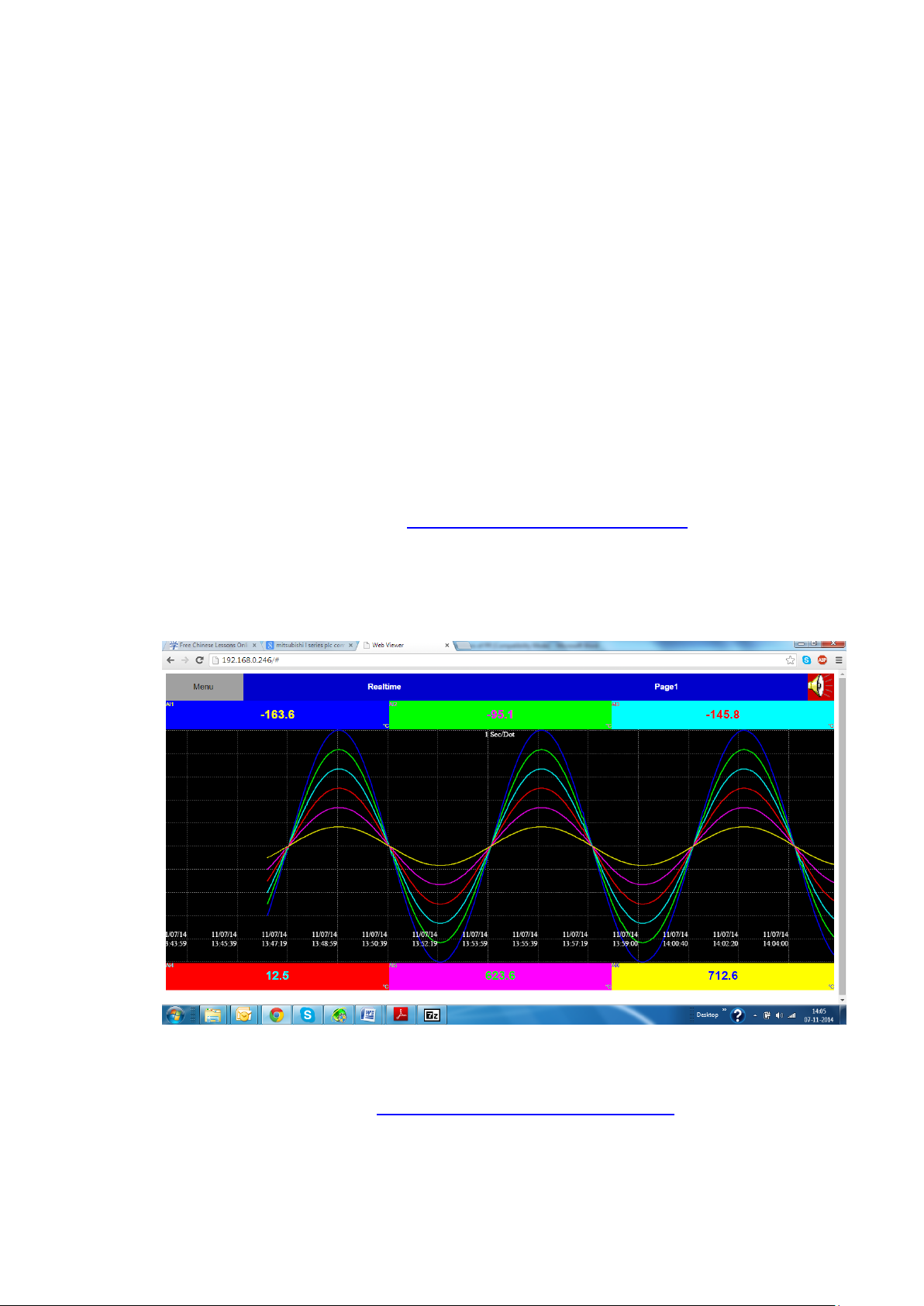
Page 55 of 479
3.3 Pulse input through Digital input
The recorder will support pulse input up to 100Hz via digital input. The digital input can be
configured as pulse counter to count the no of pulses.
3.4 PID control with Ramp & Soak Profile function
The recorder has the option to use PID control function by using PC201 PID process control
card. The PID Control Module includes Ramp & Dwell function. It is useful to control the process with
varying set point time to time. There are 50 different Profiles can be configured with 32 Segments/Profile
with the limit of 1000 Segments totally.
3.5 On Field Calibration
The Device allows the user to do on field calibration for the device. No need to send the device
to factory for Calibration.
Note: The calibration must be carried out by a skilled person with proper instruments.
3.6 Communication with Third Party Interfaces
The Recorder has the flexibility to communicate with Third party Interfaces via protocols such as
Modbus TCP/IP or Modbus RTU as either a Modbus Master or Modbus Slave. The detailed configuration
and related information are available in Chapter 5 Configuration, and Section 5.9.
3.7 Web Server
The Recorder Trend and Digital data can be viewed in any place in the world if we have Web
Server connectivity. For this the Recorder should be connected to Internet with a fixed IP address provided
by the Internet Service provider.
3.8 Email
All Important system events and alarms can be sent as an email. The detailed configuration and
related information are available in Chapter 5, Configuration, and Section 5.9.5.
Page 56
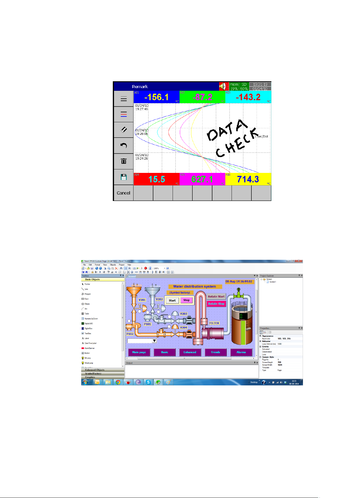
Page 56 of 479
3.9 Handwriting Messages on Historical Trend Screens
Handwriting Messages on Historical trend screen is a useful feature for the user to highlight
important events. The User can write handwritten messages using a stylus on Historical Trend screens.
This is shown in the below picture.
3.10 Custom Display Screen
In plus 2 and plus 3 versions of firmware the recorder allows the user to download the custom
screens linked with Analog and Digital Tags from the custom display editor software Panel Studio. The
custom display screens are called custom page in the recorder. The software used to create custom screen
called as custom screen editor (Panel studio).
3.11 Log Speed Flexibility
The recorder has various log speed flexibility for the user to select as per their requirement. The
available log speeds are 100ms/Dot, 1 Sec/Dot, 2 Sec/Dot, 5 Sec/Dot, 10 Sec/Dot, 15 Sec/Dot, 20 Sec/Dot,
30 Sec/ Dot, 1 Min/Dot, 2 Min/Dot, 5 Min/Dot, 10 Min/Dot, 15 Min / Dot, 1 Hour/Dot, 2 Hour/Dot. The User
has a lot of flexibility in logging speeds to select as per the application requirement.
Page 57

Page 57 of 479
3.12 System Clock Synchronization via Internet
The Recorder System clock can be synchronized via internet and Summer Saving Time can be
defined. The detailed configuration and related information are available in Chapter 5, Configuration, and
Section 5.8.
3.13 Increased Security
The security mode can be configured as normal or CFR-21. For normal, there is only one
password can be defined for configuration. For CFR-21, there are 9 levels of password with 30 users can be
defined for different functions. The detailed configuration and related information are available in Chapter 5,
Configuration, and Section5.11.
3.14 Auto Output to Printer
The Historical data can be directly printed automatically by a printer or can be saved as a PDF
file using PDF printer. The detailed configuration and related information are available in Chapter 5,
Configuration, and Section 5.13.
3.15 External Channels
Besides on-board AI and DI inputs, the recorder can accept inputs through Modbus
communication. The PR10, PR20, and PR30 can have a maximum of up to 24, 48 and 96 channels
respectively. The detailed configuration and related information are available in Chapter 5, Configuration,
and Section 5.9..
3.16 Batch
Using this function, the recorded data can be stored in batches. This makes it easy for the user
to analyse the historical data.
3.17 FDA 21 CFR PART 11
This feature is meant to comply with U.S. Food and Drug Administration with human health
concern. When this feature is enabled, the recorded data cannot be manipulated.
3.18 Circular Chart
PR30 has a unique feature to display the trend in circular chart mode. The recorder has various
log speed flexibility for the user to select as per their requirement. The available log speeds are 100ms/Dot,
1 Sec/Dot, 2 Sec/Dot, 5 Sec/Dot, 10 Sec/Dot, 15 Sec/Dot, 20 Sec/Dot, 30 Sec/ Dot, 1 Min/Dot, 2 Min/Dot,
5 Min/Dot, 10 Min/Dot, 15 Min / Dot, 10 Min/Page, 30 Min/Page, 1 Hour/Page, 2 Hour/Page, 4 Hour/Page,
8 Hour/Page, 12 Hour/Page, 1 Day/Page, 2 Day/Page, 1 Week/Page, 2 Week/Page, 4 Week/Page,
1 Hour/Dot, 2 Hour/Dot. The User has a lot of flexibility in logging speeds to select as per the application
requirement.
Page 58
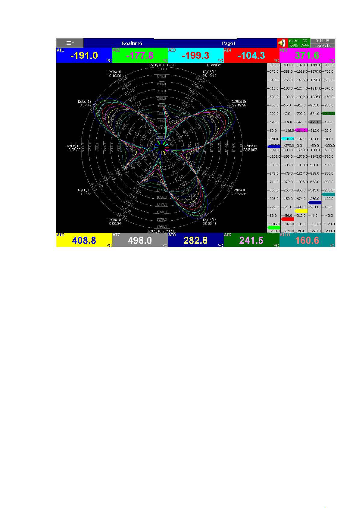
Page 58 of 479
3.19 Multilingual Languages
The recorder provides multiple language options for the user to select as per their convenience.
The available languages are Brazil Portuguese, Chinese (Simplified, Traditional), Czech, Danish, Dutch,
English, French, German, Greek, Italian, Japanese, Korean, Polish, Portuguese, Russian, Spanish,
Swedish, Thai, Turkish. Other Languages negotiable.
3.20 USB Barcode Reader, Keyboard and Mouse Connectivity
The recorder supports the data entry through USB Keyboard, Mouse and Barcode reader for the
configuration.
Page 59
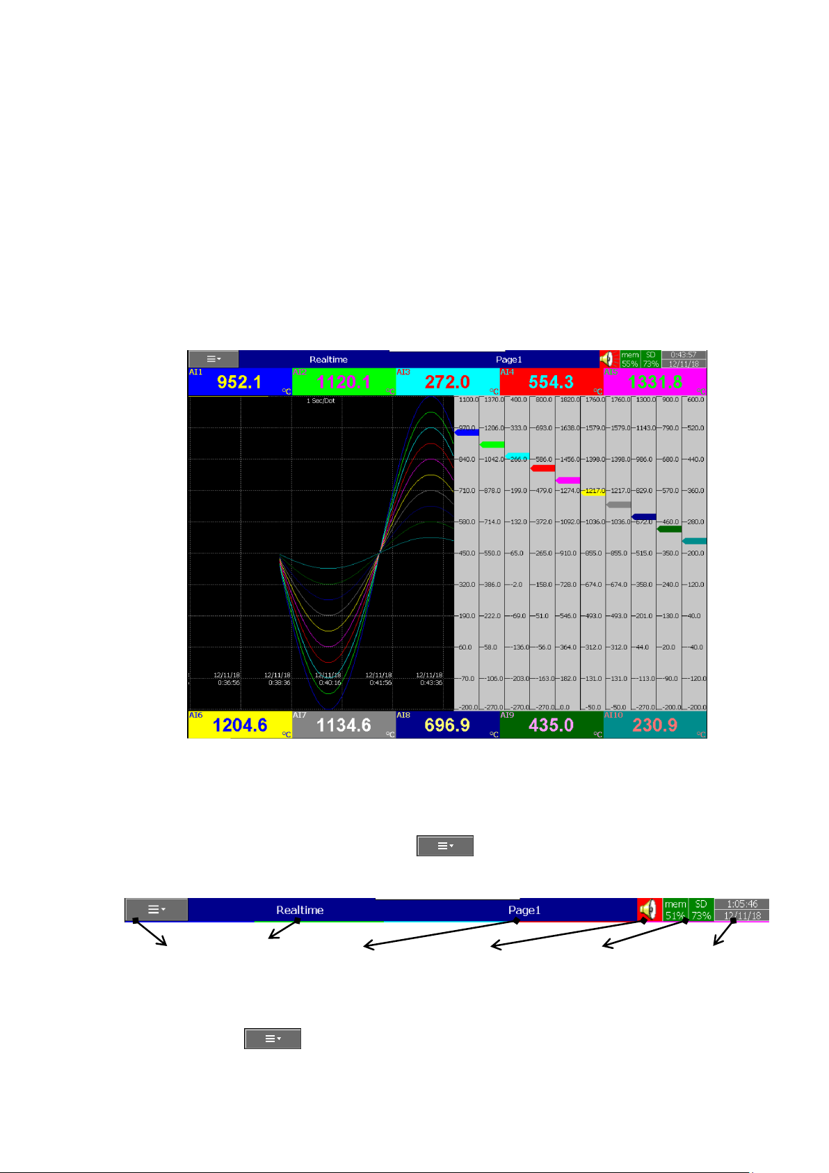
Page 59 of 479
4. GETTING STARTED
The recorder has a TFT touch screen display capable of complex graphical representation,
internal memory and SD card slot or USB drive slot for data storage. The unit is easily programmable, and
the average user will probably never need to use most of the features or functions available in the recorder.
This chapter will give the user a brief system overview and guide the first-time user in a simplified setup
which will enable you to begin recording with the least amount of effort.
4.1 Screen Navigation
The recorder has a TFT touch screen which shows graphics. The screen that also acts as a touch
keypad. The user has only to lightly touch the screen area to operate. If the Beep volume is enabled then
the unit will provide a short audible beep, each time the screen is touched. The default display of the
recorder which shows after power on is as below.
The screen is divided into two distinct areas such as Title Bar, across the top of the screen and
the Graphics Area below the Title bar.
4.1.1 Title Bar
The Status Bar consists of Menu key , Page Type, Page Name, Alarm Status, Internal
memory status, External memory status, Date and Time.
4.1.1.1 Menu key
The menu key will allow the user to access the menus available in the recorder. When the user
press the menu key , the available menus are displayed.
Menu key Page Type Page Name Alarm Status Internal and Memory Status Date and Time
Page 60
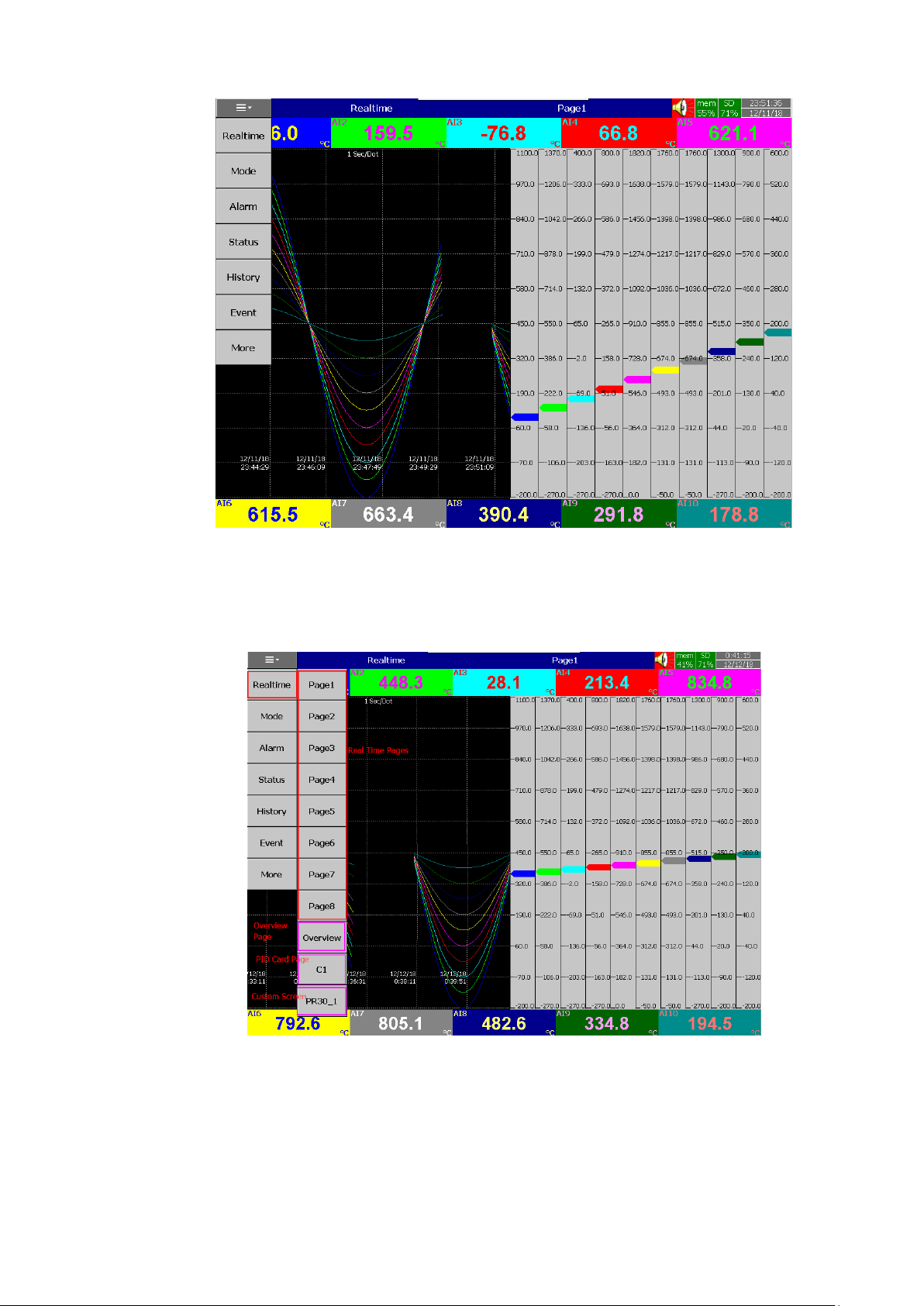
Page 60 of 479
4.1.1.1.1 Real Time
Real time menu will allow the user to access the real time display of the configured display
pages, Overview display, PID Control card display page and custom screen display page.
4.1.1.1.2 Mode
Mode Menu will allow the user change the graphical display mode. The available display modes
are Trend, Bar Graph, Digital, Mix Mode, Individual Mode and Circular Mode (only for PR30).
Page 61
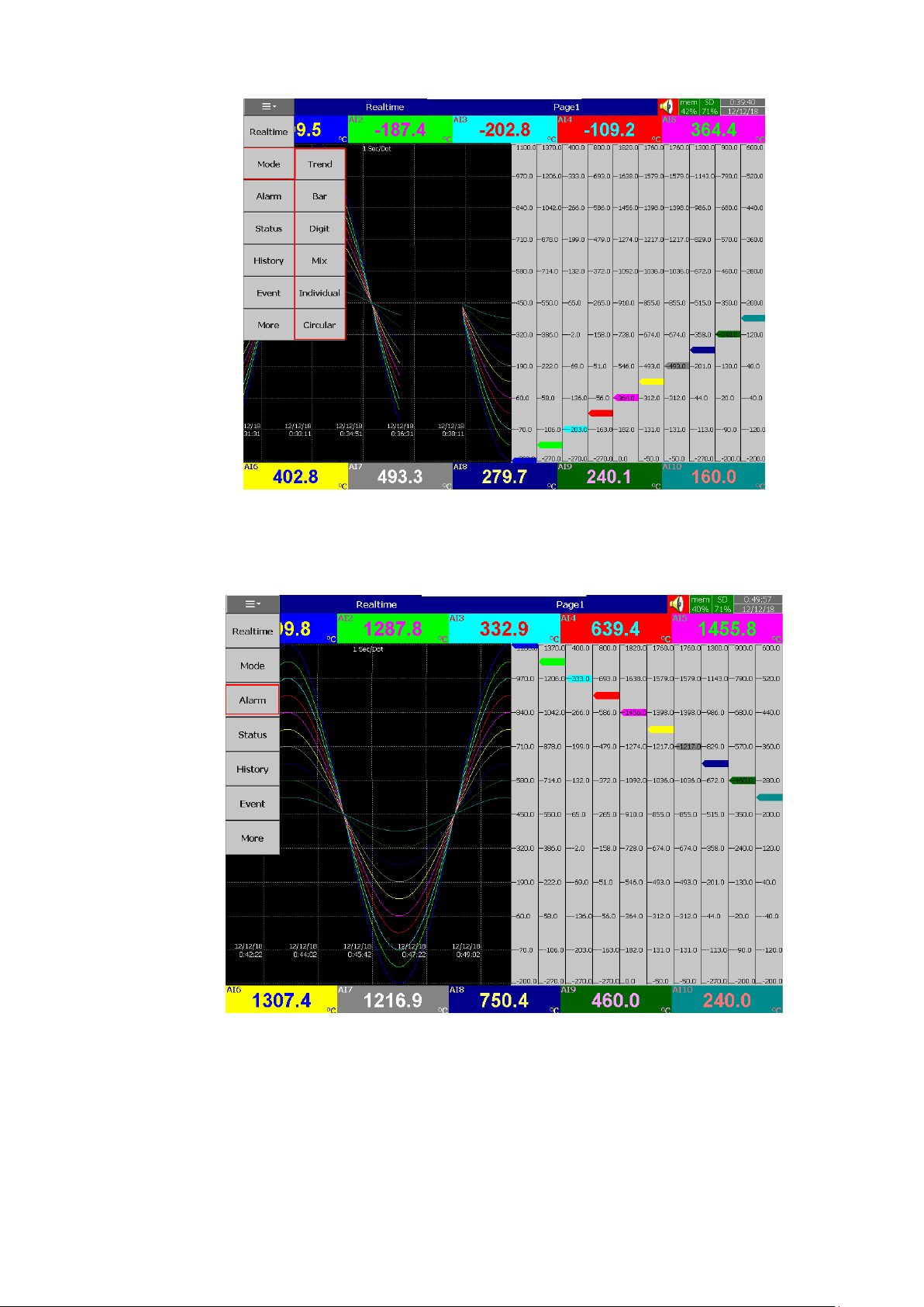
Page 61 of 479
4.1.1.1.3 Alarm
Alarm menu will allow the user to access the real time alarm page. In this page the user can
view the real time alarms and acknowledge the alarms.
Page 62
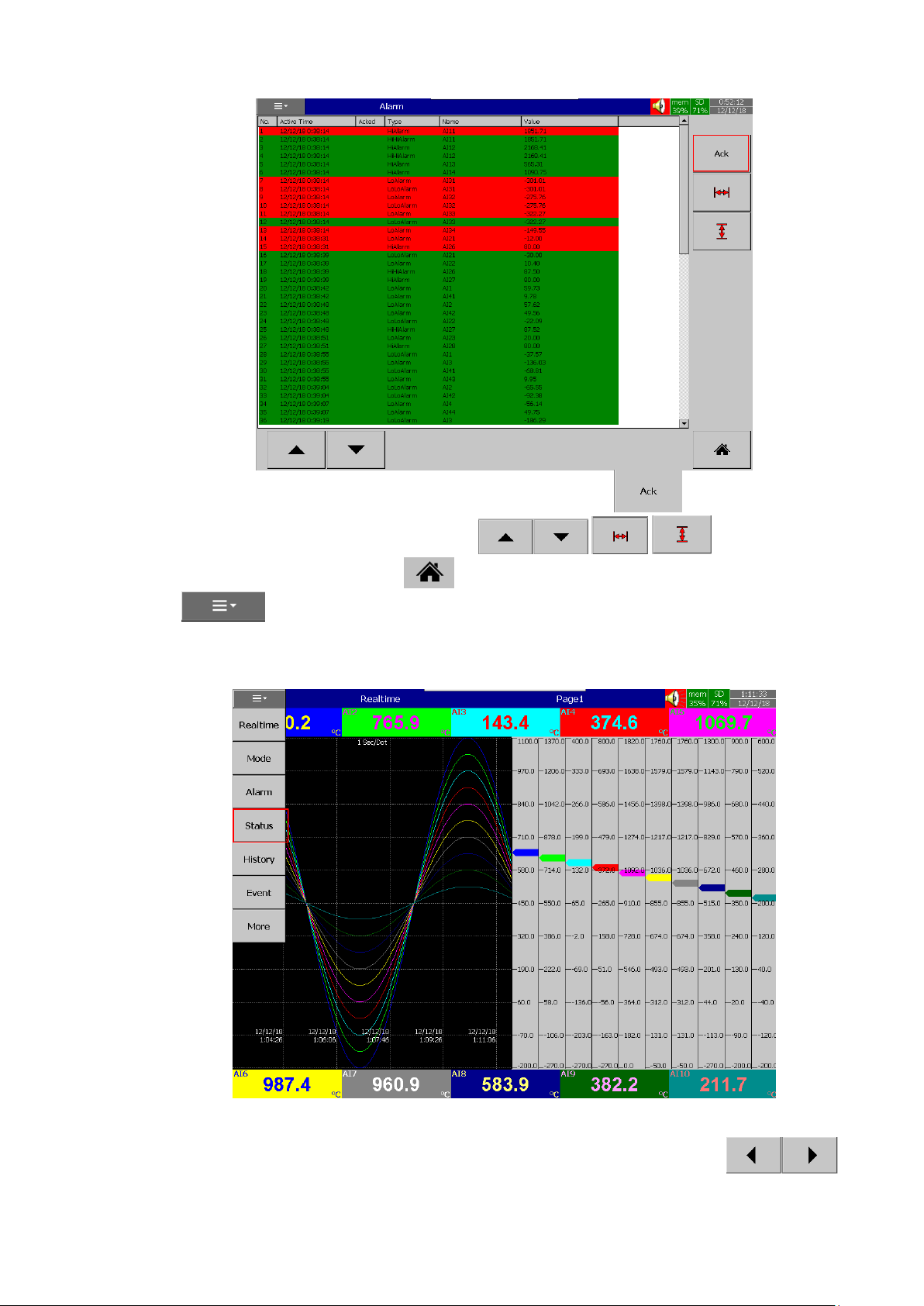
Page 62 of 479
The user can acknowledge the alarm by pressing the ACK key. The user can
navigate the alarm display by using the scroll keys . The user can go back
to Home screen by pressing the Home key. The user can access other menus by pressing the
menu key.
4.1.1.1.4 Status
Status menu will show the status of DI, DO, AO, Totalizer, Counter.
By using the DI, DO, AO, Counter, Totalizer tabs the individual status can be viewed in the
respective tabs. The selected tab can be changed by using the left and right scroll keys .The
Page 63
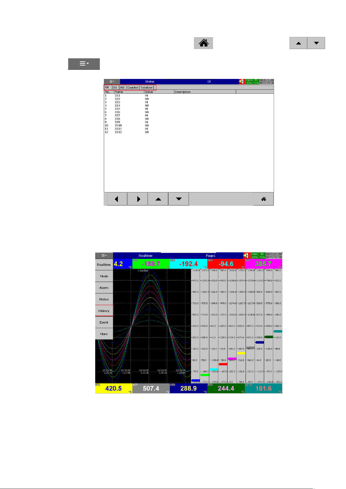
Page 63 of 479
user go back to the home screen by pressing the Home key. The up down scroll keys
are used to scroll down the pages in individual tabs. The user can access other menus by pressing the
menu key.
4.1.1.1.5 History
History menu will allow the user to access the historical data of the display pages. The user can
select the required historical display page by pressing the required page key in the history menu.
Page 64
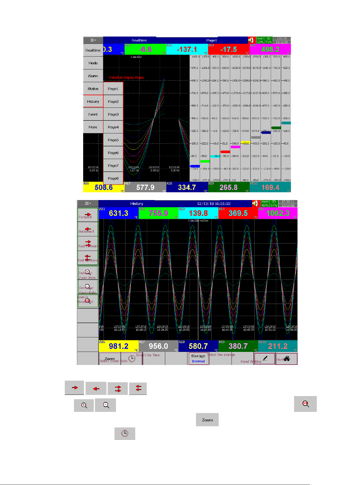
Page 64 of 479
The historical display page will allow the user to navigate the historical data and do the
handwritten remarks on the display page. The user can do the navigation on the screen using the four scroll
keys . The user can increase or decrease the zoom rate by using the two
softkyes . The hand written messages within the data can be searched by using
key. The zoom rate can be selected by using the soft key . The data at the particular time can be
serached by the soft key . The location of displayed data can be switched between internal memory
Page 65
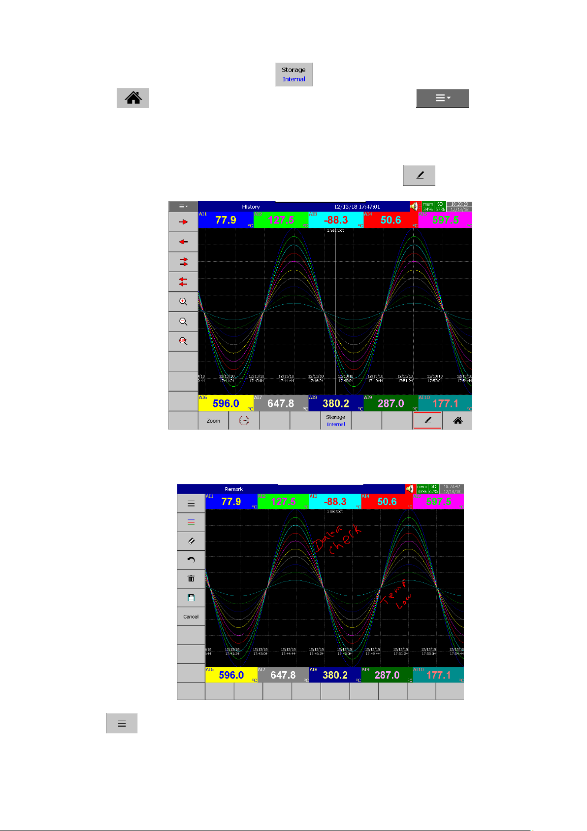
Page 65 of 479
and external memory by using the softykey . The user go back to the home screen by pressing the
Home key. The user can access other menus by pressing the menu key.
4.1.1.1.5.1 Handwriting Messages on Historical Trend Screens
Handwriting Messages on Historical trend screen is a useful feature for the user to highlight
important events. The User can write handwritten messages using a stylus on Historical Trend screens.
If the User wants to write a message, then they can press the pen key in the screen
below.
Then using the stylus, the user can write any message in Historical Trend Pages as shown
below.
If the User wants to change the width of the written message, he/she can choose the width
key to change the width of the pen.
Page 66
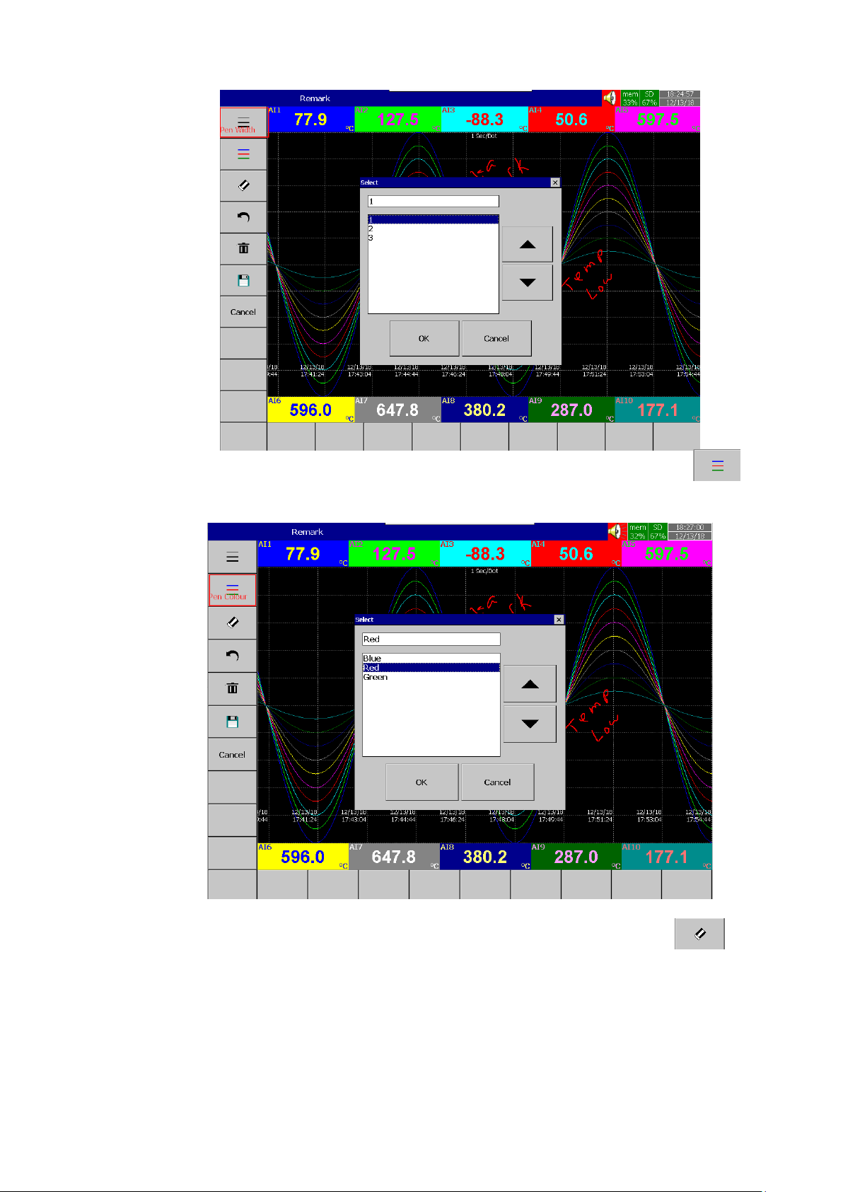
Page 66 of 479
If the User wants to change colour of the pen, he/she can change it by using the key to
change the color of the pen.
If the User wants to erase part of a message, he/she can do this by using the key to
erase part of the message.
Page 67
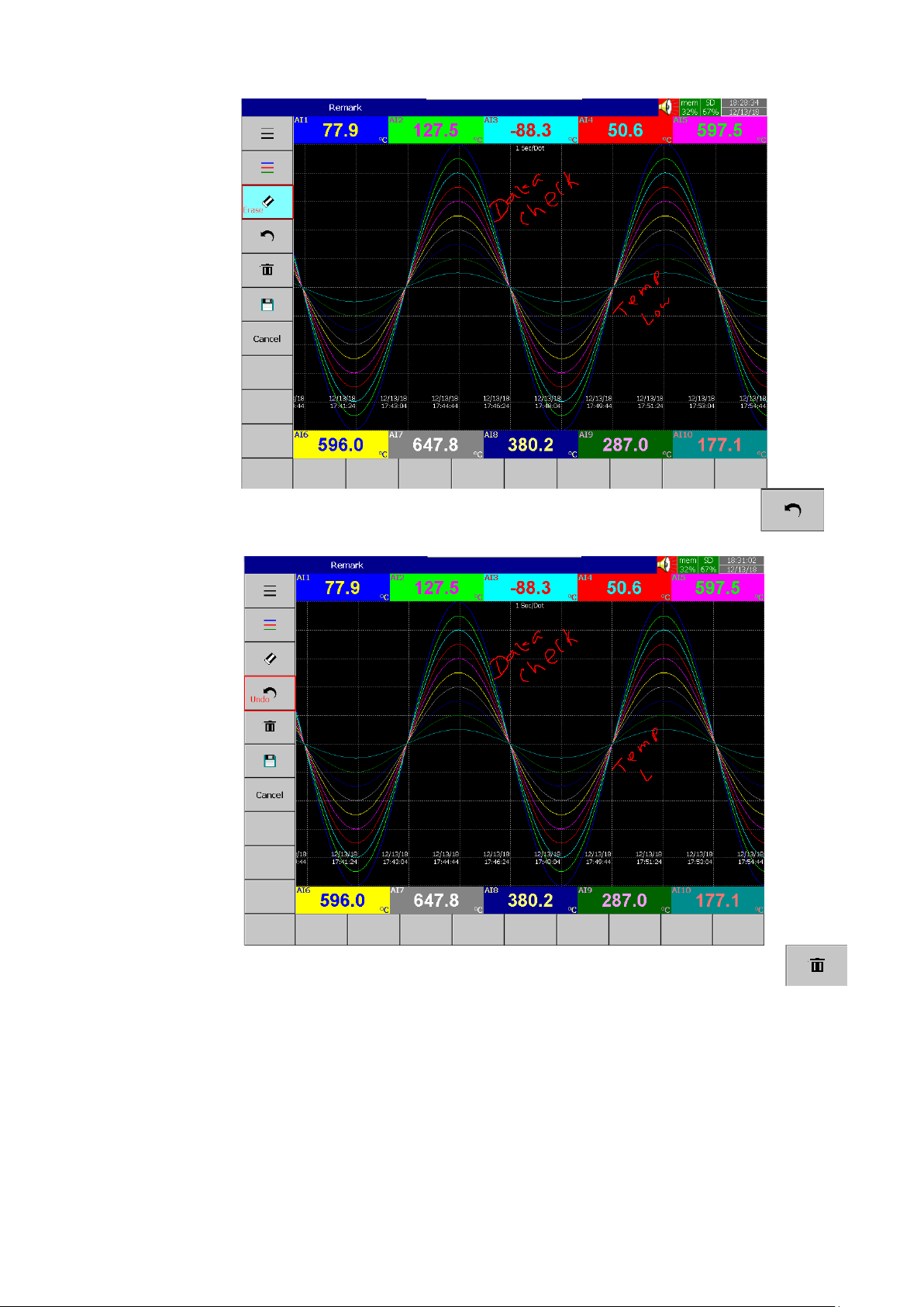
Page 67 of 479
If the user wants to undo part of a message, he/she can do this by using the key to
undo the last part of the message.
If the User wants to delete the written message, he/she can this do by using the key to
delete the written message.
Page 68
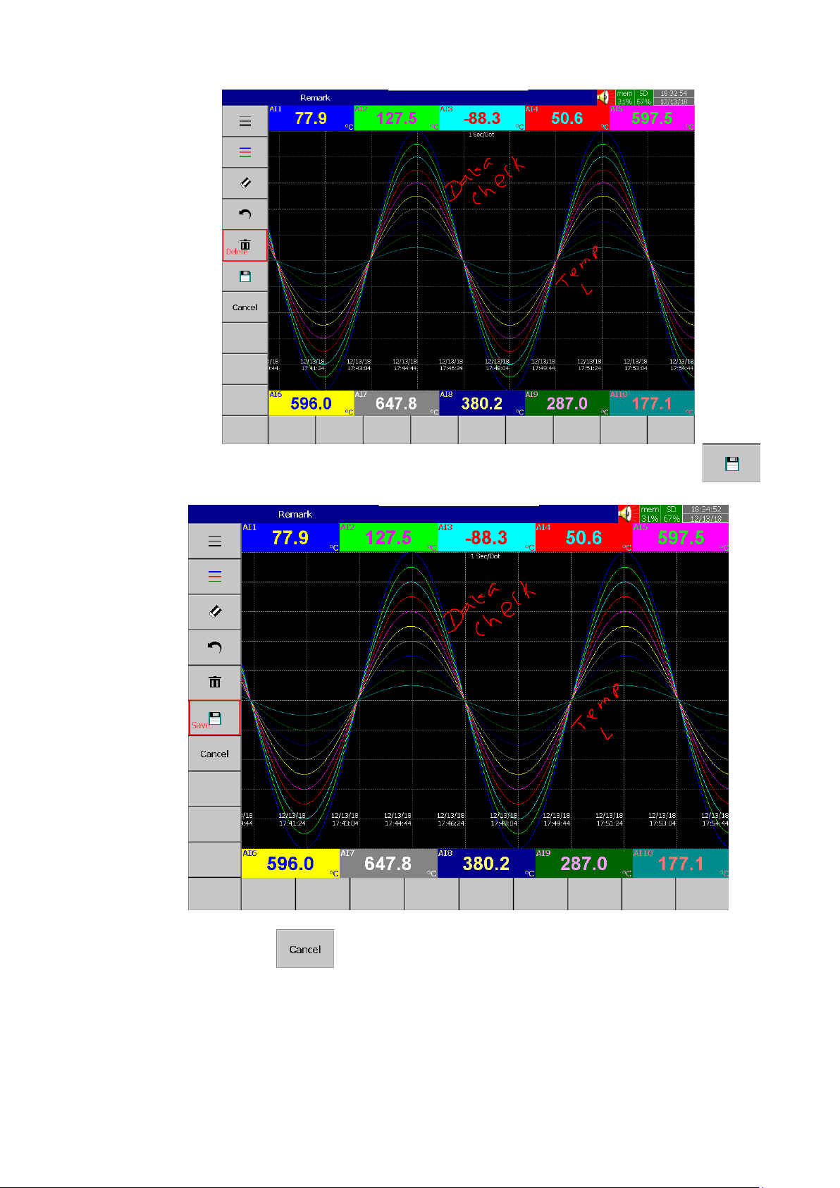
Page 68 of 479
If the user wants to save the written message, he/she can do this by using the key to
save the written message.
By using the key, the user can exit the page without saving the data.
Note: The handwriting messages are saved once can’t modified or deleted.
Page 69
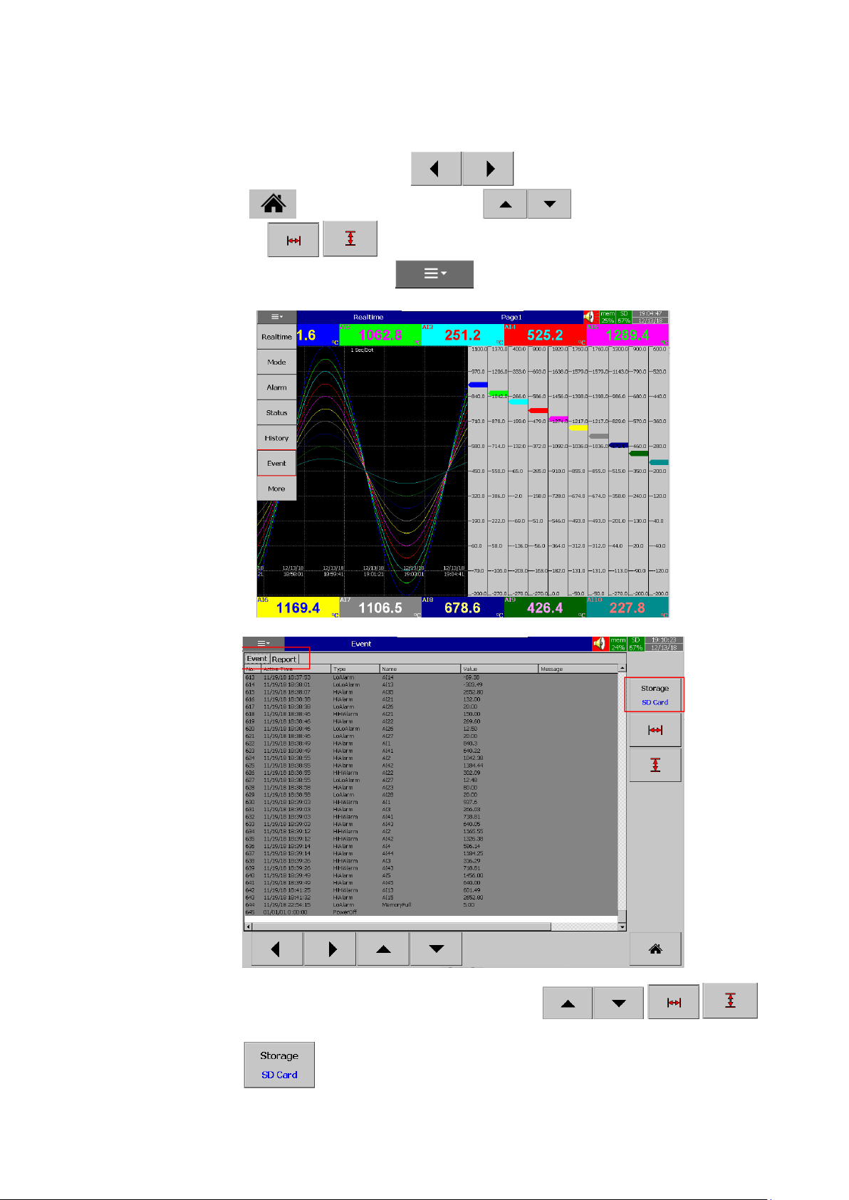
Page 69 of 479
4.1.1.1.6 Event
Event menu will allow the user to access the historical events and reports. By using the Event
and Report tabs the event list and report list can be viewed in the respective page. The selected tab can be
changed by using the left and right scroll keys .The user go back to the home screen by
pressing the Home key. The up down scroll keys are used to scroll down the pages
in individual tabs. The keys are used to navigate rows and columns. The user can
access other menus by pressing the menu key.
The Event list can be navigated by using the scroll keys . The
stored location of displayed historical events cane be switched between internal memory and SD card by
using the softkyey .
Page 70
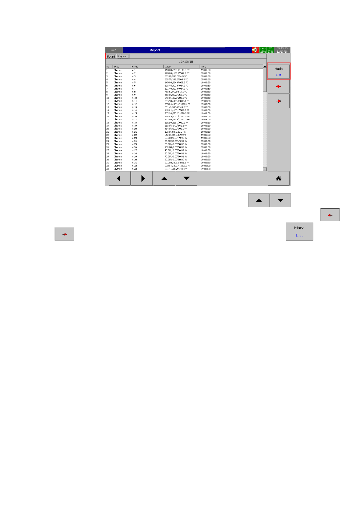
Page 70 of 479
The Report list can be navigated up and down by using keys. The report
of previous and next day,week, month depends on the selection of mode can be navigated by using
keys. The mode can be switched between List, Daily, Weekly,Monthly by using key.
4.1.1.1.7 More
More menu will allow the users to access more menus for the operation. The more consists of
the below menus.
1. Dump
2. Clear
3. Operate
4. Config
5. Stop
6. Logout
7. Batch
8. Shutdown
Page 71
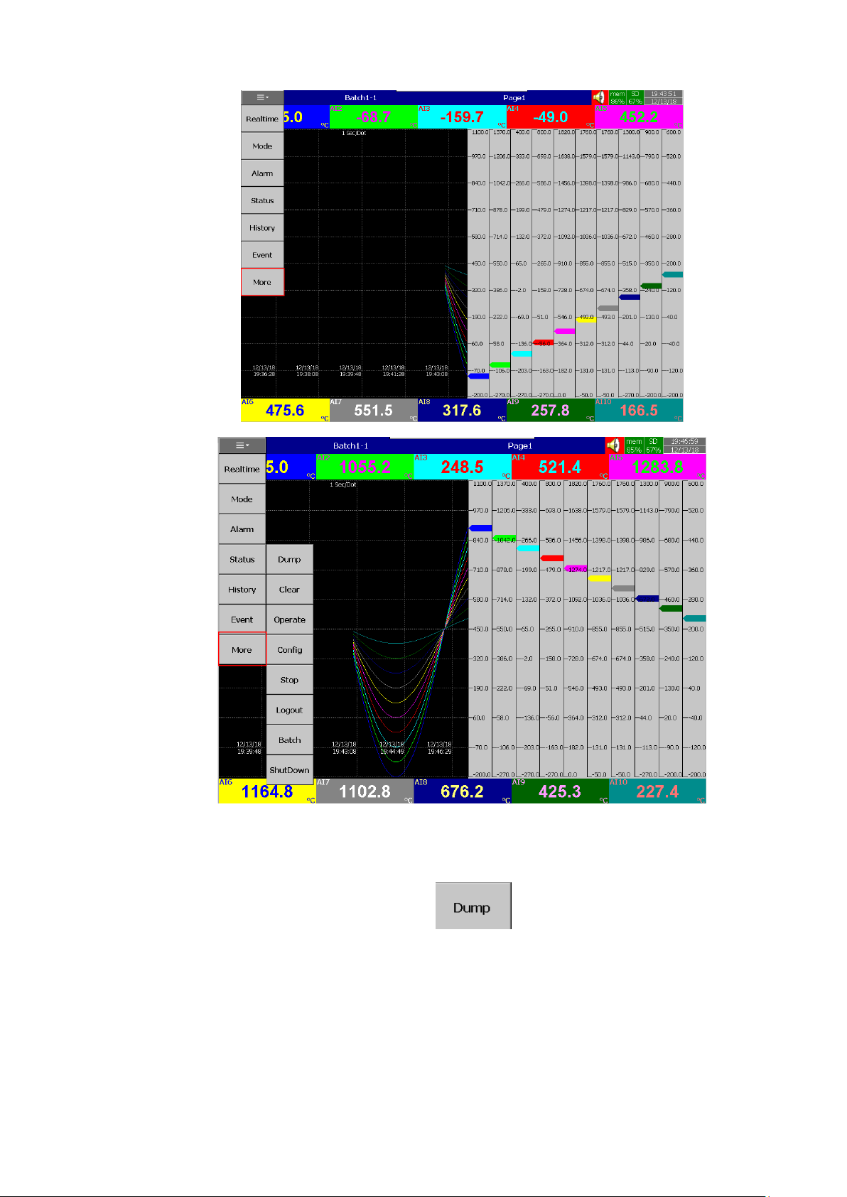
Page 71 of 479
4.1.1.1.7.1 Dump
Dump the historical data from internal memory to external memory such as SD Card or USB
Disk. The user can select the data to be dumped to external memory. The recorder will allow the user to
select the period to be dumped after pressing the key. The available period option to be
selected will be differ for normal mode and batch mode.
Page 72
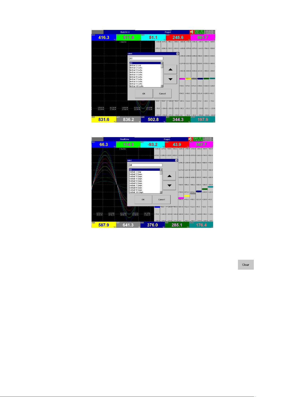
Page 72 of 479
Dump Option-Batch Mode
Dump Option- Normal Mode
4.1.1.1.7.2 Clear
Clear all the historical data and event list stored in the memory. The user can select the data to
be cleared. The recorder will allow the user to select the period to be cleared after pressing the key.
The available option period to be selected will be differ for normal mode and batch mode.
Page 73
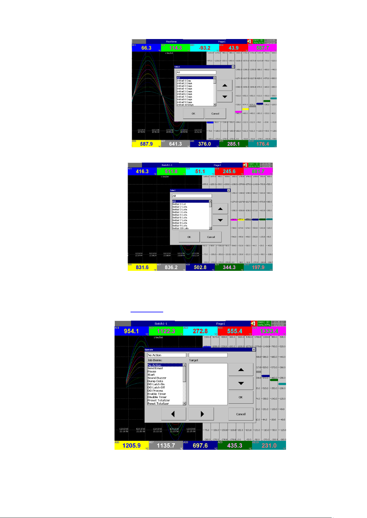
Page 73 of 479
Clear Option- Normal Mode
Clear Option-Batch Mode
4.1.1.1.7.3 Operate
Manually operate the jobs from the available jobs directly without any events. The details of
all the jobs are explained in section 5.3.
Page 74
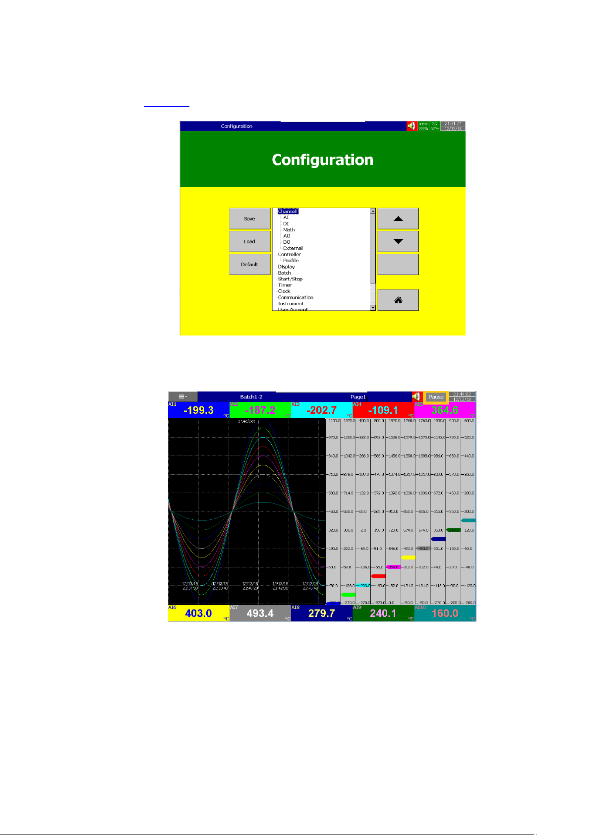
Page 74 of 479
4.1.1.1.7.4 Config
This will allow the user to access the configuration page. The configuration page configuration is
explained in Chapter 5.
4.1.1.1.7.5 Stop
Stop the batch and logging. The Title bar will show pause when the logging is stopped.
Logging Paused
4.1.1.1.7.6 Logout
Logout the user.
4.1.1.1.7.7 Batch
The user can configure the batch related information. The information can be configured
are Batch name, Lot no, Batch comments. There are 10 comments are available for the user to configure.
Page 75
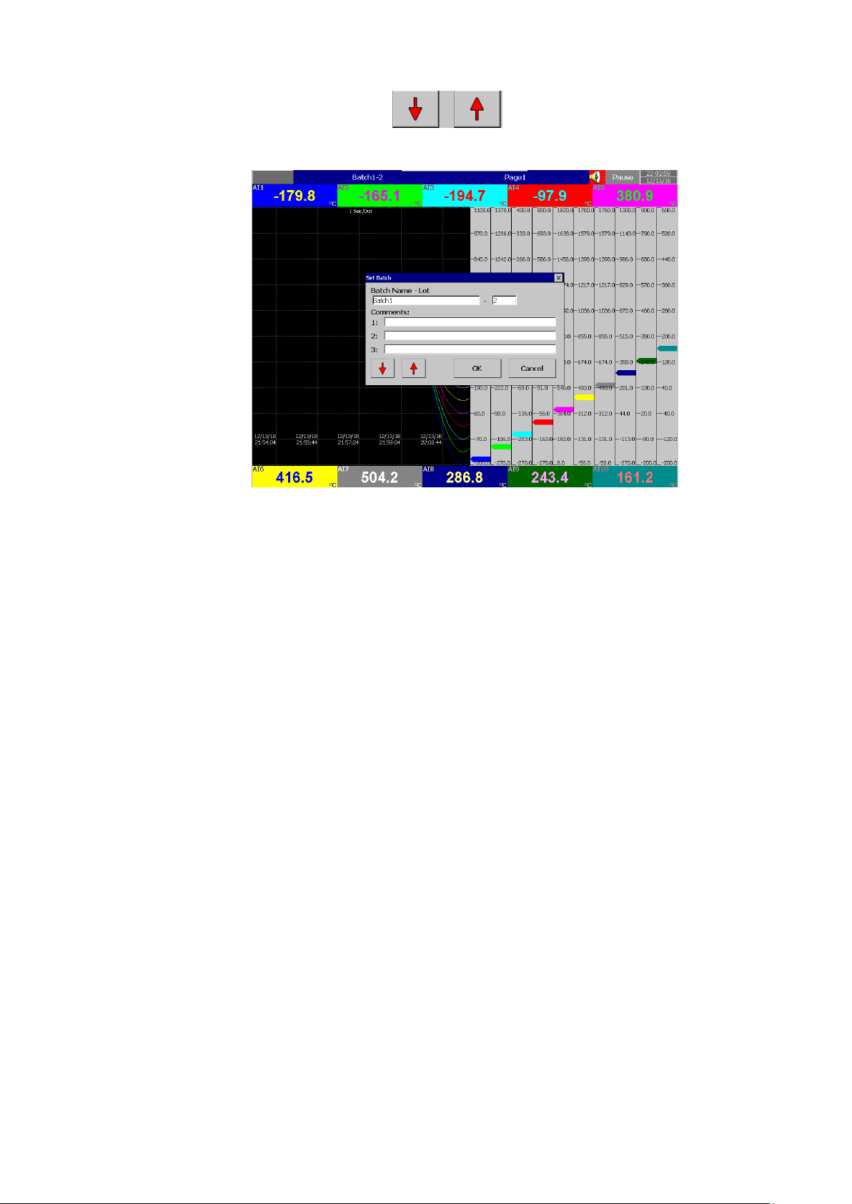
Page 75 of 479
The comments can be navigated by using keys. The Batch name and lot no can’t be
edited during the batch is running.
4.1.1.1.7.8 Shutdown
Shutdown the recorder.
Page 76
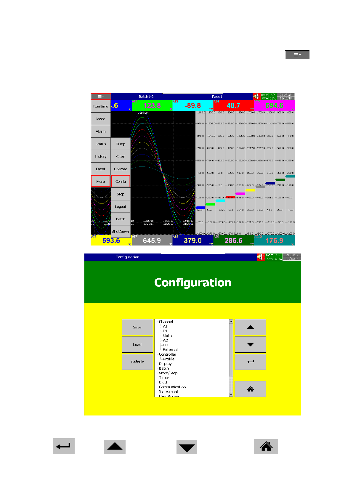
Page 76 of 479
5. CONFIGURATION
This section will explains about the procedure to configure the recorder. Press (Menu),
then More and then Config soft key to enter Configuration mode. A tree type layout appears with a
provision to configure Channel, Tools, Message, Display, Instrument, Security, Auto-Output, Demo, and
system Information. In addition, the Save, Load, Default and Home soft buttons also appear.
There are four soft keys are available in the configuration page for the menu navigation. They
are as below.
Enter key Up directional key Down directional key Home key
Page 77
Page 77 of 479
Various options are available to enter into configuration page menus.
Option-1: Select the required menu by using up & down directional keys, then press “Enter” key
Option-2: Select the required menu directly with a touch, then press “Enter” key
Option-3: Select the required menu by pressing the menu two times quickly, it is same as a double click
from a mouse
There are four soft key are available to save, load, to load the default settings and move to home
screen. They are below.
Save
Save configuration from the recorder to a USB disk or an SD Card.
Load
Load configuration from a USB Disk or SD Card to the recorder.
Default
Load the factory default setting to the configuration menu parameters.
Home
Returns the display back to the home page.
5.1 Channel
This section will explains the configuration of different types of channels. They are as below.
1. Analog Input (AI)
2. Digital Input (DI)
3. Math
4. Analog Output (AO)
5. Digital Output (DO)
6. External device channels.
5.1.1 Analog Input
After entering the Configuration menu, in “Channel”, select “AI”, then Press the “Enter” key to
get into Analog Input Channel configuration menu. It displays the Analog input AI1 as the first analog input
channel configuration page. Press directional navigation keys at the bottom to select
other channels. Press directional keys on the right hand side to select the column.
After completing Configuration, press soft key, then press soft key to return to
main display. All configurations will be saved automatically.
Page 78
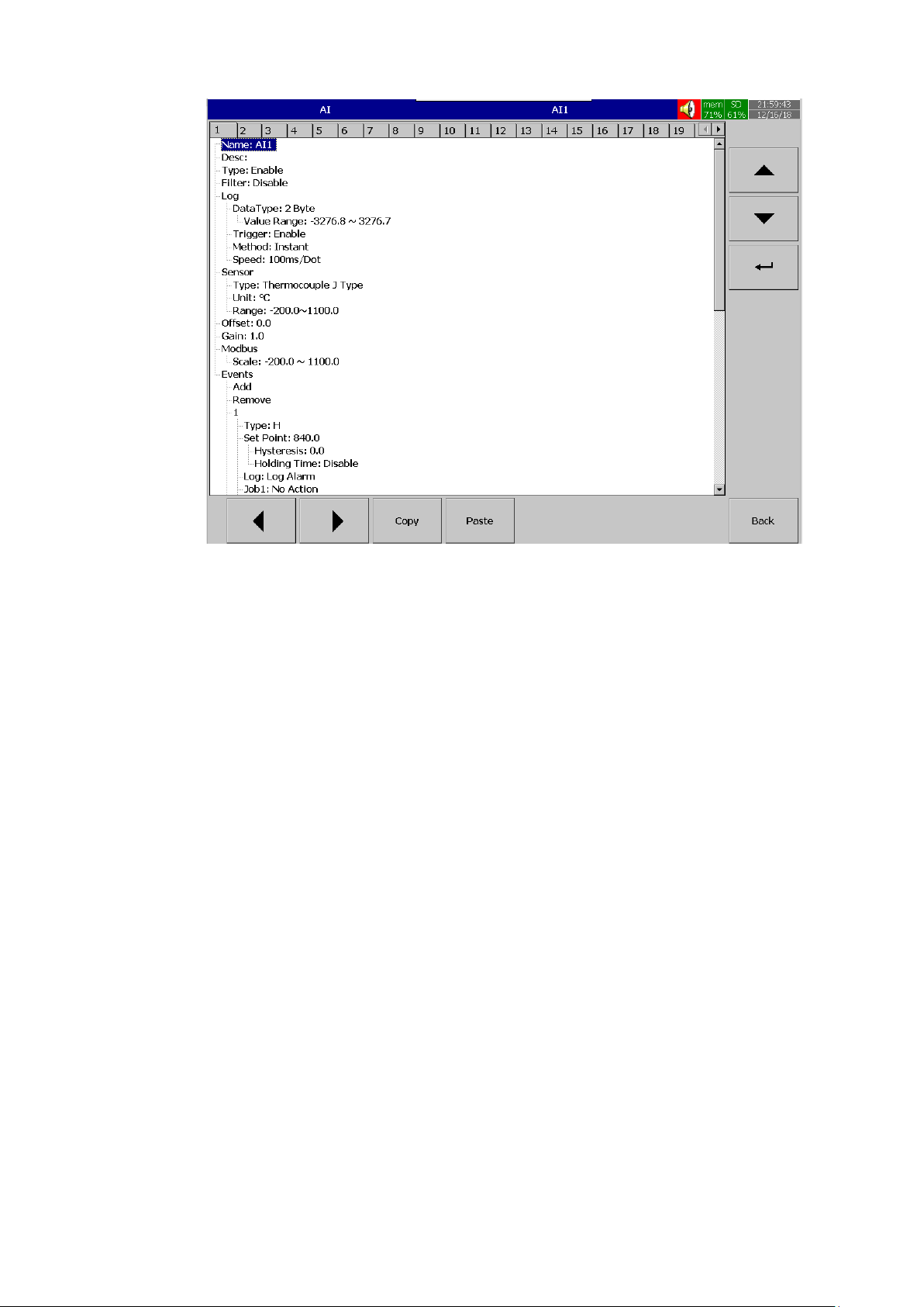
Page 78 of 479
Copy: copy the channel configuration from one channel to another channel.
Paste: Paste the copied configuration to the channel.
Press Copy key in the source channel and press paste key in the destination channel.
5.1.1.1.1 Name
Enables the User to define the name for each channel with a maximum of 18 characters.
Select “Name”, then Press “Enter”, soft key, a keyboard with several keys will appear. Press “Shift” to
select special characters. Press “Caps” to select capital letters. Press soft key “OK” after entering a new
channel name.
5.1.1.2 Desc
The description about a specific channel on the recorder.
5.1.1.3 Type Option available to enable or disable the channel
5.1.1.4 Filter It is to reduce the noise of input signal before logging. The filter can be set from 1 second to 16
seconds. It is a soft filter available to reduce fast variation of analog inputs. There are two types of filters
available for the users to select. They are moving average and difference.
5.1.1.4.1 Moving Average
This will log average of the values sampled in the configured Buffer Time.
For example, if the filter value is set as 5 sec for AI1, it means all the samples collected in the
last 5 sec shall be averaged, and the averaged value is available to record as per Log method.
Page 79
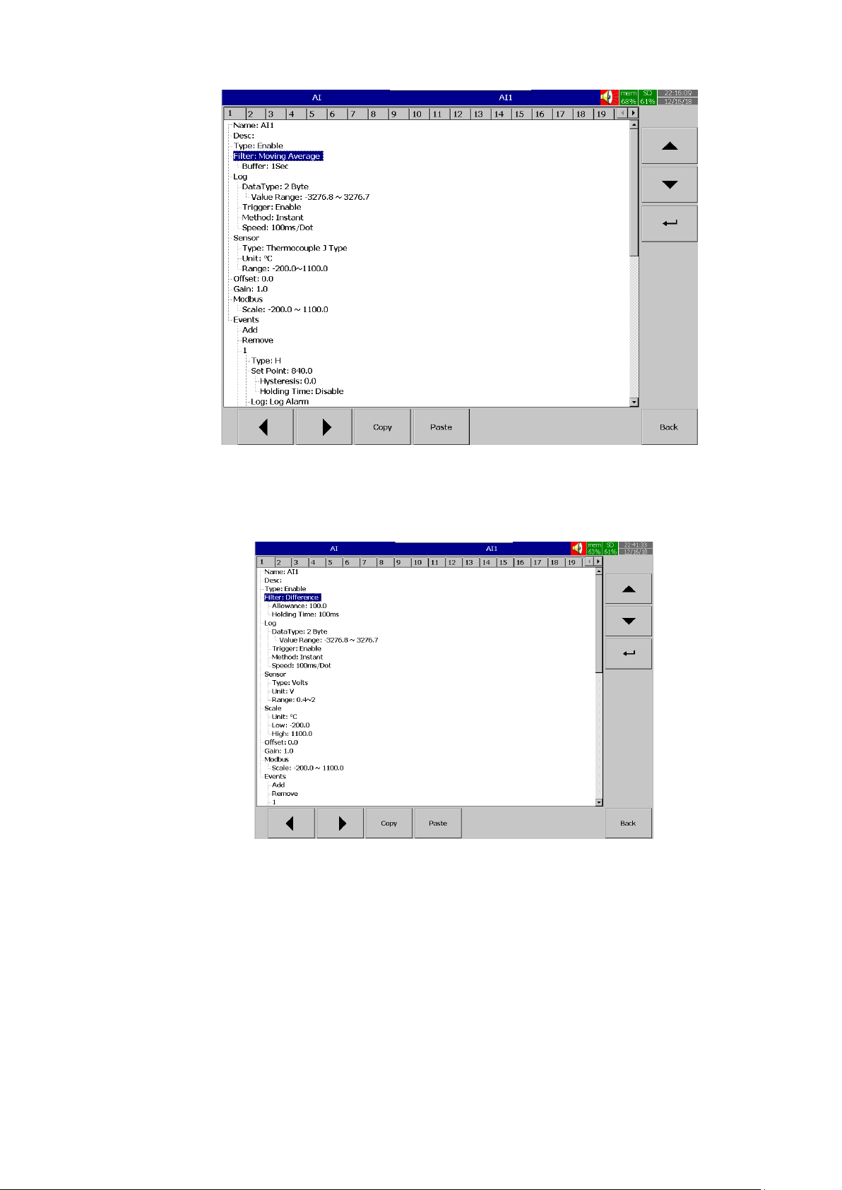
Page 79 of 479
5.1.1.4.2 Difference
This will log the data only there is at least a difference between the current data and the last
logged data for a period. The difference will be defined by allowance and the period is defined by holding
time.
For example, the allowance is set for 100 and the holding time is set for 100 msec. If current
value is 1000 and last value is 890, when you check the difference is 110. Since this difference is greater
than 100 it is with that value more than the holding time 100 msec, this value will be recorded. If the
difference of current and last recorded value is greater than “difference value” but does not stay for the
duration of holding time this value will not be recorded. So the holding time will define the duration of noise
filter.
Page 80

Page 80 of 479
5.1.1.5 Log
5.1.1.5.1 Data Type
The data type for logging is 2 byte.
2 byte range: -32767 to +32767
5.1.1.5.2 Trigger
Two options are available for the user to select.
1. Disable: Select disable while the recording of a specific channel is not required at this time
2. Enable: Select enable while the recording of a specific channel is required at this time
5.1.1.5.3 Method
This is the method of logging measured data. Select the column Method and press Enter. Then
choose the required Log method from the available methods Instant, Average, Minimum or Maximum of
data.
5.1.1.5.3.1 Instant Logging the last measured data at the logging interval
5.1.1.5.3.2 Average
Logging the averaged of sampled measured data at the logging interval
5.1.1.5.3.3 Minimum
Logging the minimum of sampled measured data at the logging interval
5.1.1.5.3.4 Maximum
Logging the maximum of sampled measured data at the logging interval
5.1.1.5.4 Speed
It is the logging speed (recording speed) of measured data. The available log speeds are as
below.
1. 100 msec/dot
2. 1 Sec/dot
3. 2 Sec/dot
4. 5 Sec/dot
5. 10 Sec/dot
6. 15 Sec/dot
7. 20 Sec/dot
8. 30 Sec/dot
9. 1 min/dot
10. 2 min/dot
11. 5 min/dot
12. 15 min/dot
13. 1 hour/dot
14. 2 hour/dot
Page 81
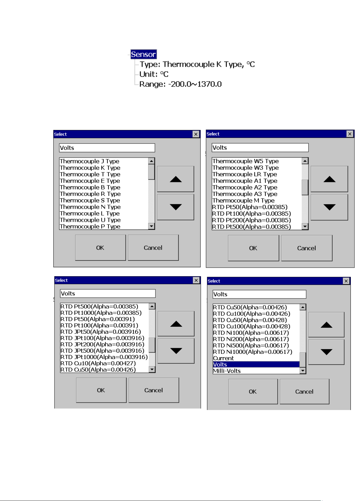
Page 81 of 479
5.1.1.6 Sensor
5.1.1.6.1 Type
Select the input type of the sensor for the channel.
5.1.1.6.2 Unit
The engineering unit of input.
5.1.1.6.3 Range
Select the range for the input based on Sensor type
Page 82

Page 82 of 479
5.1.1.6.4 Scale
Appears only for linear input type. The user can scale the input to the engineering unit as per the
application requirement.
5.1.1.7 Offset
It is to offset the input value to correct the sensor error.
5.1.1.8 Gain
It is a multiplier to correct the sensor error.
The correct value = (the process value x gain) + offset
5.1.1.9 Modbus
The scaling of the channel value in Modbus communication.
5.1.1.10 Events
Events are frequently used for Alarm purposes. The events can be used to operate digital
outputs (DO), Timer, Totalizer, Counter or Report. There are maximum five events can be added to each
analog input.
Press “Add” to add new event and Press “Remove” to remove selected event
5.1.1.10.1 Type
There are various types of events are available for the user to select for job or alarm purpose.
They are listed as below.
5.1.1.10.1.1 H
It is high event. When the process value is higher than high limit, then the alarm or job
associated with this event is actuated.
5.1.1.10.1.2 L
It is low event. When the process value is lower than low limit, then the alarm or job associated
with this event is actuated.
5.1.1.10.1.3 HH
It is high high event. When the process value is higher than high high limit, then the alarm or job
associated with this event is actuated. This is another limit higher than high limit for double warning.
5.1.1.10.1.4 LL
It is low low event. When the process value is lower than low low limit, then the alarm or job
associated with this event is actuated. This is another limit lower than low limit for double warning.
5.1.1.10.1.5 Dev+
It is deviation+ event. This event will be triggered on the positive deviation of process value. The
job or alarm is activated when the process value is deviated by the value higher than set point from the
previous process value.
Page 83

Page 83 of 479
For example,
Set point =10
At 10.00.01 Hrs, Tag1=40
At 10.00.02 Hrs, Tag1 = 51
Then, job or alarm is activated
5.1.1.10.1.6 Dev-
It is deviation- event. This event will be triggered on the negative deviation of process value. The job or
alarm is activated when the process value is deviated by the value lower than set point from the previous
process value.
For example,
Set point =10
At 10.00.01 Hrs, Tag1=40
At 10.00.02 Hrs, Tag1 = 29
Then, job or alarm is activated.
5.1.1.10.1.7 Error
It is error event. This event will be activated when there is an error on the input of the channel.
5.1.1.10.2 Set point
Set point for the event.
5.1.1.10.2.1 Hysteresis
To avoid the alarm or event been activated too often, Hysteresis value can be defined for the
event trigger set point.
5.1.1.10.2.2 Holding time
To avoid the alarm or event been activated too often, the holding time can be defined for the
event trigger set point. In process sometimes SP is reached but it will go down immediately, this might due
to process instability. To avoid these kind of nuisance situations, the holding time can be used to see that
PV stays at above that SP more than the holding time and then only activate the action for that event. The
range of holding time can be set from 1 min to 60 min.
5.1.1.10.3 Log
The event can be logged as alarm or event. They can be selected from the available options. They are as below.
5.1.1.10.3.1 Log Alarm
Log the event as Alarm.
5.1.1.10.3.2 Log Alarm (Auto Ack) Log the event as alarms and acknowledge automatically
5.1.1.10.3.3 Log Event Log as event
Page 84
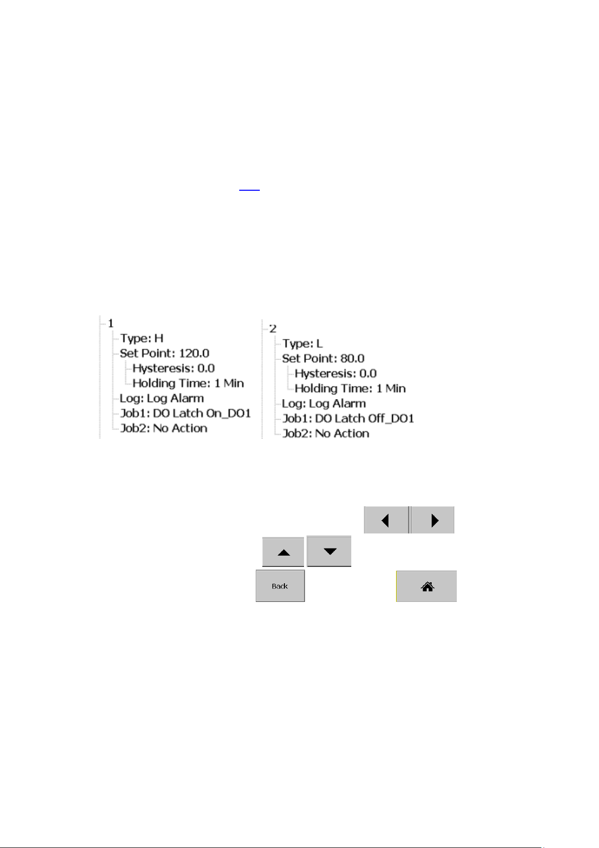
Page 84 of 479
5.1.1.10.4 Job1 & Job2
The job is called as a task to be performed when the event is activated. There are two jobs Job1
and Job2 can be added to perform in any event.
A typical example is to trigger an alarm buzzer in the event of a high temperature. Each
channel can accept five different types of events (or alarms) and each event can create two jobs. Please
note that a job under Event is different from a job perform by Operate key. The job is actuated by an event,
and the Operate is actuated by manual control, no event necessary.
Note: Please refer to the section Jobs for full details about various jobs available
Note: Number of analog inputs shown on the AI screen depends on number of Analog input cards inserted
in the paperless recorder.
Example:
If the temperature is increased to more than 120 OC, logs alarm and switches on digital output 1
only after 1 minute holding time defined in the setting. When the temperature is decreased to less than 80
O
C, logs the alarm and switches off the digital output1 only after 1 minute holding time defined in the setting.
Setting of events for the analog input in the channel configuration is as follows,
5.1.2 Digital Input
After entering the Configuration menu, in the Channel, select DI then Press the “Enter” soft key
to get into Digital Input Channel configuration menu. . It displays the Digital input DI1 as the first digital input
channel configuration page. Press directional navigation keys at the bottom to select
other channels. Press directional keys on the right hand side to select the column.
After completing Configuration, press soft key, then press soft key to return to
main display. All configurations will be saved automatically.
Page 85
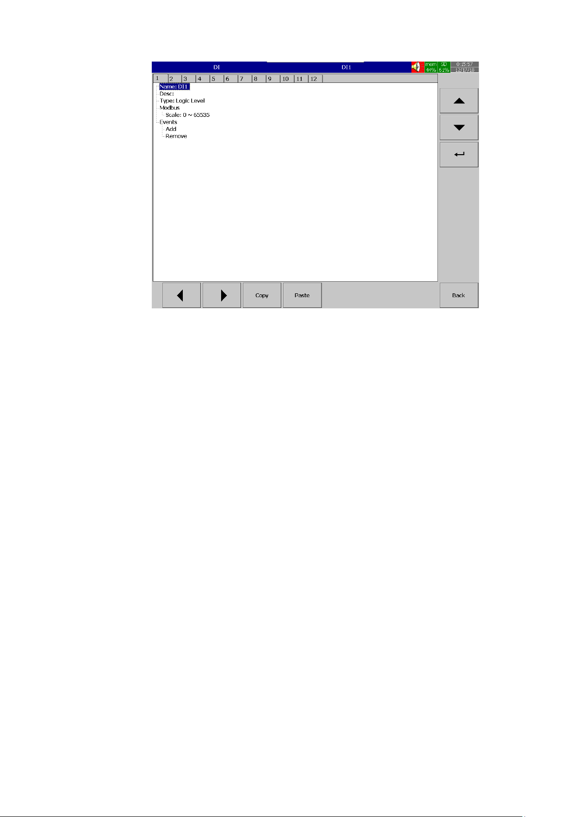
Page 85 of 479
Copy: copy the channel configuration from one channel to another channel.
Paste: Paste the copied configuration to the channel.
Press Copy key in the source channel and press paste key in the destination channel.
5.1.2.1.1 Name
Enables the User to define the name for each channel with a maximum of 18 characters.
Select “Name”, then Press “Enter”, soft key, a keyboard with several keys will appear. Press “Shift” to
select special characters. Press “Caps” to select capital letters. Press soft key “OK” after entering a new
channel name.
5.1.2.2 Desc
The description about a specific channel on the recorder.
5.1.2.3 Type
Type of Digital input. The digital input can be configured as Logic Level and pulse counter. To
select the type press the Type and then select the required type.
5.1.2.3.1 Logic Level
This selection activates digital logic, which is either one or zero with low frequency which is less
than 1Hz, such as an external relay.
5.1.2.3.2 Pulse Counter
This selection will allow the digital input to read the high speed pulse inputs up to 100 Hz. This is
useful to get the flow rate from pulse output from flow meters.
Page 86
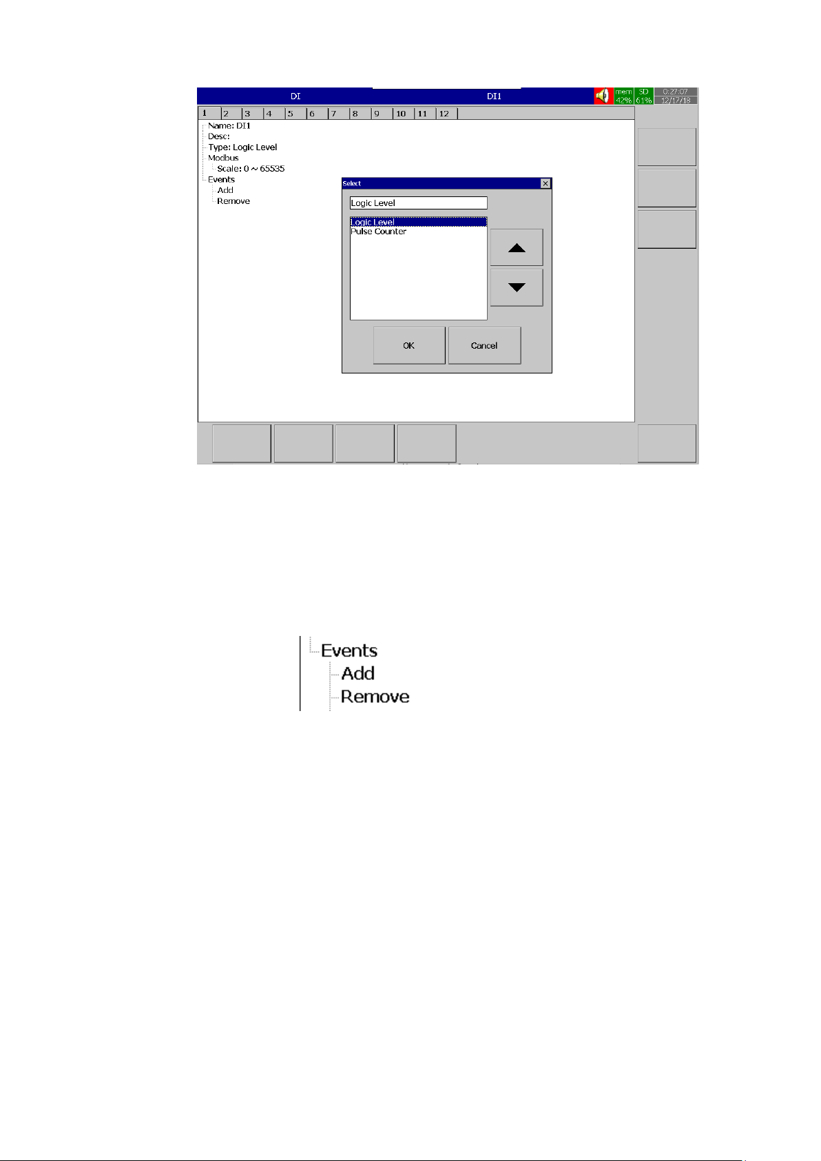
Page 86 of 479
5.1.2.4 Events A maximum of 2 events are supported for every digital Input channel. A maximum of two jobs
can be configured for each event.
*Note: Events will not appear if Logic Level selected as Pulse Counter
Press “Add” to add new event and Press “Remove” to remove selected event
5.1.2.4.1 Type
Select the event type Low L or High H
5.1.2.4.1.1 Holding time
To avoid the alarm or event been activated too often, the holding time can be defined for the
event trigger set point. In process sometimes SP is reached but it will go down immediately, this might due
to process instability. To avoid these kind of nuisance situations, the holding time can be used to see that
the DI stays at high or low more than the holding time and then only activate the action for that event. The
range of holding time can be set from 1 min to 60 min.
5.1.2.4.2 Job1, Job2
The job is called as a task to be performed when the event is activated. There are two jobs Job1
and Job2 can be added to perform in any event.
To configure a Job, select Job1, the press the Enter key. It will show a list of all the available
jobs. Select the required Job.
Page 87
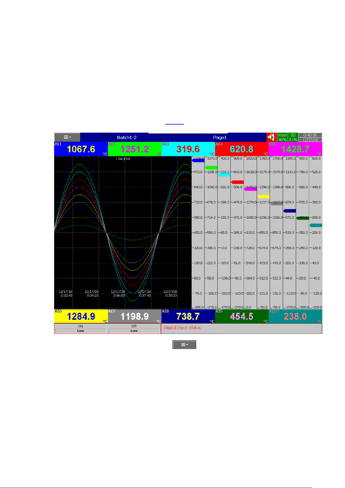
Page 87 of 479
Note: Number of digital inputs shown one the DI screen depends on number of Digital input cards inserted
in the paperless recorder.
Example:
After pressing a “Start” switch, latch ON Digital Ouput1, after pressing a “Pause” switch, latch Off
Digital Output1.
Start Timer, Stop Timer, Reset Totalizer, Reset Counter, Reset MaxMinAve values of all the
channels etc...
It is possible to display Digital input status via status bar on any display page in the paperless
recorder. If digital input is not enabled then it shows as “Low”. If digital input is enabled then it shows as
“High”. To configure status bar, refer section Display
Digital Input status can also monitored from the (Menu). Press “Status” and then select “DI”, it will
show the Digital Input Status as follows.
Page 88
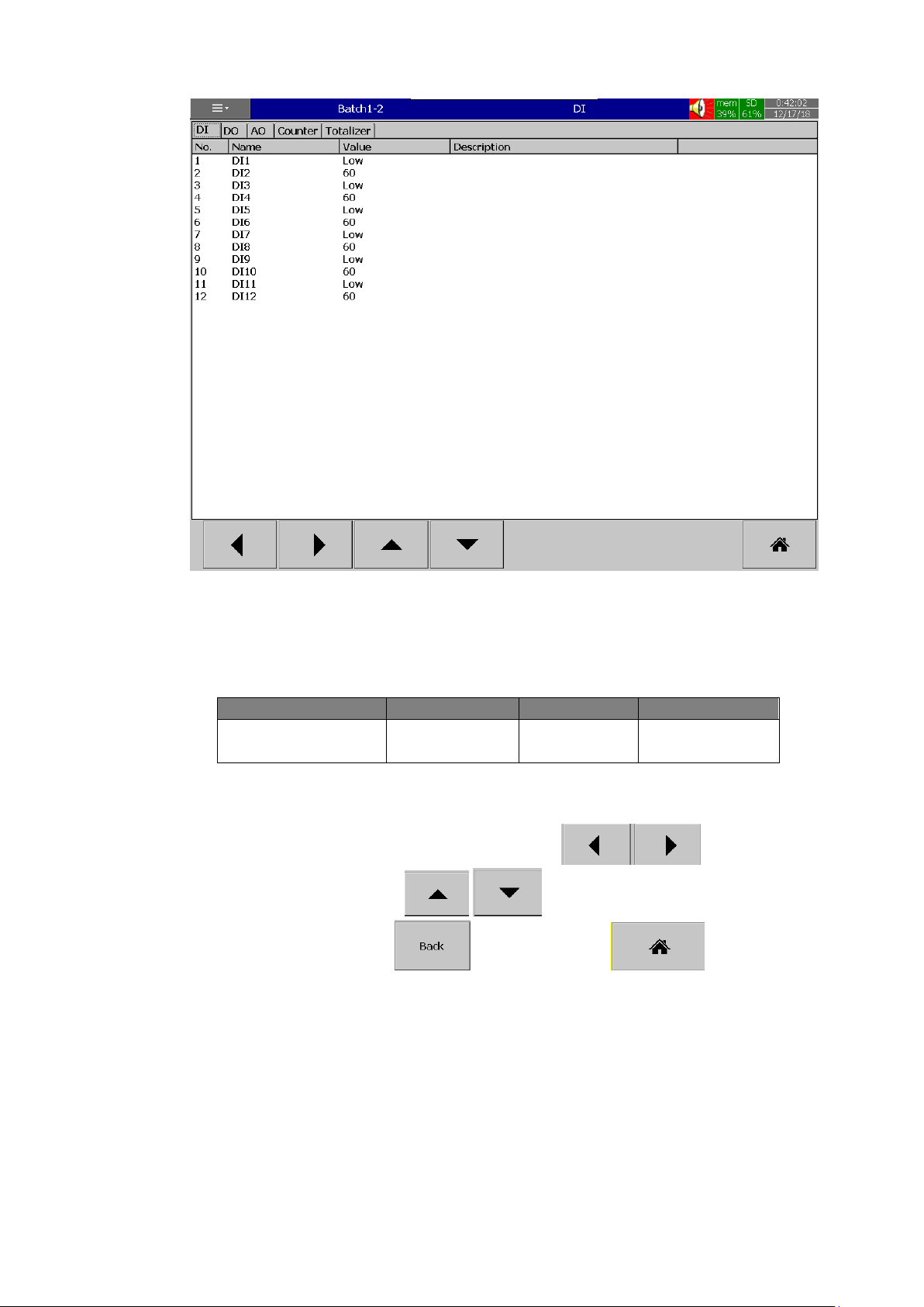
Page 88 of 479
5.1.3 Math Channel
The Math channel is used to do the mathematical operations. The Math channel can be
configured as Math or counter or Totalizer. The maximum no of math channel in different PR recorders as
below.
PR Recorder
PR10
PR20
PR30
Maximum Math
Channels
15
40
60
After entering the Configuration menu, in the Channel, select Math then Press the “Enter” soft
key to get into Math Channel configuration menu. . It displays the Math channel Math1 as the first math
channel configuration page. Press directional navigation keys at the bottom to select
other channels. Press directional keys on the right hand side to select the column.
After completing Configuration, press soft key, then press soft key to return to
main display. All configurations will be saved automatically.
Page 89
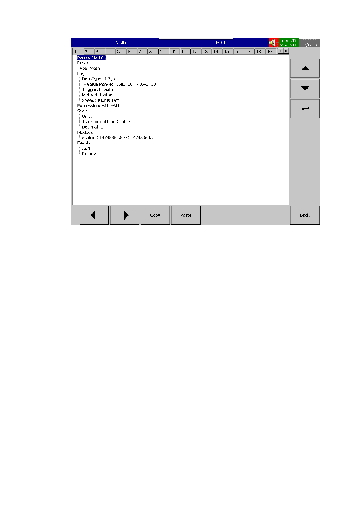
Page 89 of 479
Copy: copy the channel configuration from one channel to another channel.
Paste: Paste the copied configuration to the channel.
Press Copy key in the source channel and press paste key in the destination channel.
5.1.3.1.1 Name
Enables the User to define the name for each channel with a maximum of 18 characters.
Select “Name”, then Press “Enter”, soft key, a keyboard with several keys will appear. Press “Shift” to
select special characters. Press “Caps” to select capital letters. Press soft key “OK” after entering a new
channel name.
5.1.3.2 Desc The description about a specific channel on the recorder.
5.1.3.3 Type
The type of math channel. The math channel can be configured as Math, Counter and Totalizer.
The options available in type for the user to select are Disable, Math, Counter and Totalizer. The
configuration menu will differ depends on the selection of Type.
5.1.3.3.1 Disable
Disable the math channel.
Page 90
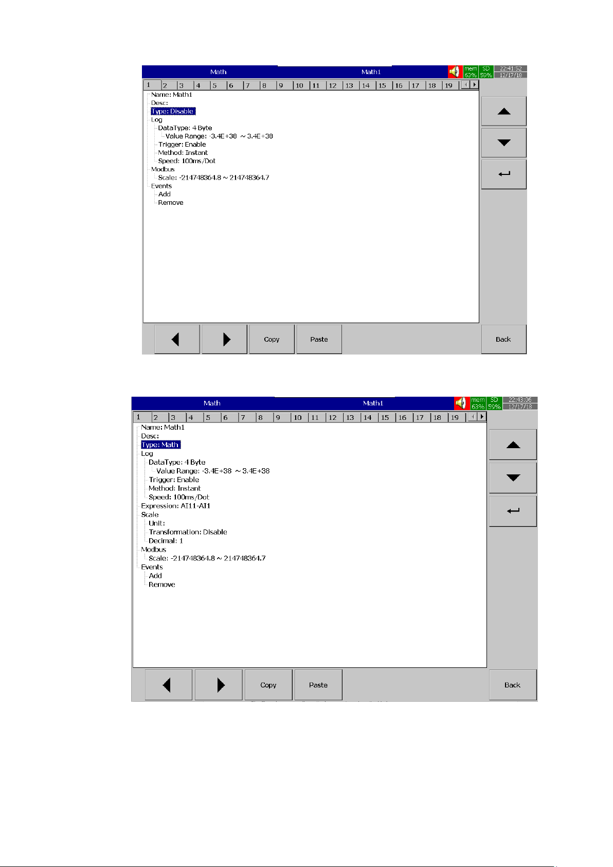
Page 90 of 479
5.1.3.3.2 Math
Configure the channel as Math channel.
5.1.3.4 Log
5.1.3.4.1 Data Type
The data type for logging is 2 byte or 4 byte
2 byte range: -32767 to +32767
4 byte range:-3.4E+38 to +3.4E +38
Page 91

Page 91 of 479
5.1.3.4.2 Trigger
Two options are available for the user to select.
3. Disable: Select disable while the recording of a specific channel is not required at this time
4. Enable: Select enable while the recording of a specific channel is required at this time
5.1.3.4.3 Method
This is the method of logging measured data. Select the column Method and press Enter. Then
choose the required Log method from the available methods Instant, Average, Minimum or Maximum of
data.
5.1.3.4.3.1 Instant Logging the last measured data at the logging interval
5.1.3.4.3.2 Average
Logging the averaged of sampled measured data at the logging interval
5.1.3.4.3.3 Minimum
Logging the minimum of sampled measured data at the logging interval
5.1.3.4.3.4 Maximum
Logging the maximum of sampled measured data at the logging interval
5.1.3.4.4 Speed
It is the logging speed (recording speed) of measured data. The available log speeds are as
below.
1. 100 msec/dot
2. 1 Sec/dot
3. 2 Sec/dot
4. 5 Sec/dot
5. 10 Sec/dot
6. 15 Sec/dot
7. 20 Sec/dot
8. 30 Sec/dot
9. 1 min/dot
10. 2 min/dot
11. 5 min/dot
12. 15 min/dot
13. 1 hour/dot
14. 2 hour/dot
5.1.3.5 Expression
This will appear only for the channel type as Math. Math channel expression can be configured
on this menu. Once the user enter the expression menu the pop up window will show the option for the user
to configure the expression. The pop up window consists of Source, Operator and key board.
Page 92
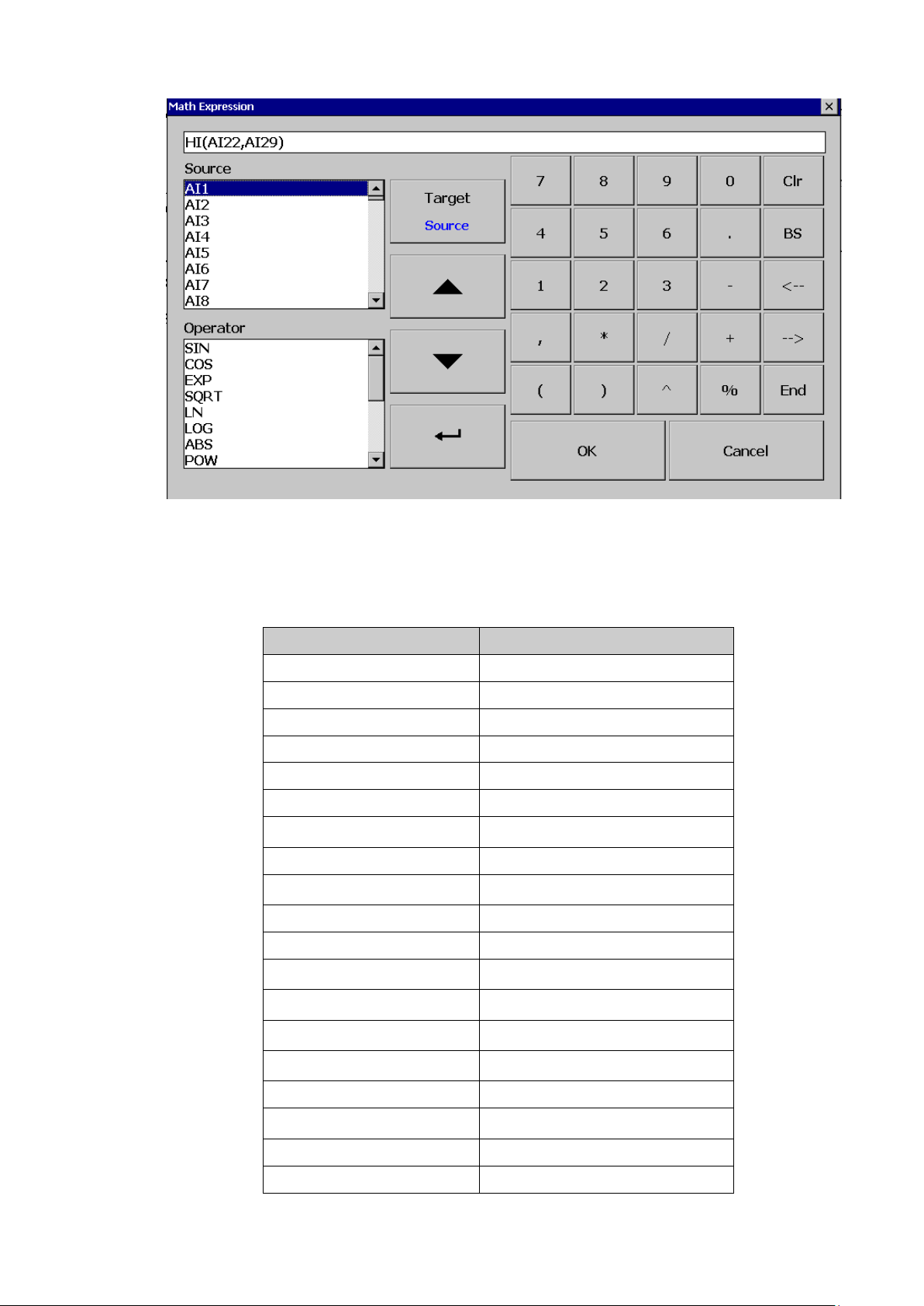
Page 92 of 479
The Source consists of all available Analog inputs, Digital Inputs, Math inputs, external channels.
The Operator consists of available mathematical expressions. Use Source, Operator and keyboard to define
the Math equation.
5.1.3.5.1 Available Math Expressions
The available math expression for the user to configure the math expressions are as below.
Expressions
Mathematics Functions
+
Addition
-
Subtraction
*
Multiplication
/
Division
SIN(x)
sin(x)
COS(x)
cos(x)
EXP(x)
ex
SQRT(x)
Square root of x
LN(x)
loge(x)
LOG(x)
log10(x)
ABS(x)
Absolute of x
POW (x,y)
xy
ROUND(x)
The closest integral number to x
HI(x,y)
The bigger value between x and y
INV(x)
1/x
TG(x)
tan(x)
CTG(x)
1/tan(x)
ASIN(x)
Sin-1(x)
ACOS(x)
Cos-1(x)
Page 93
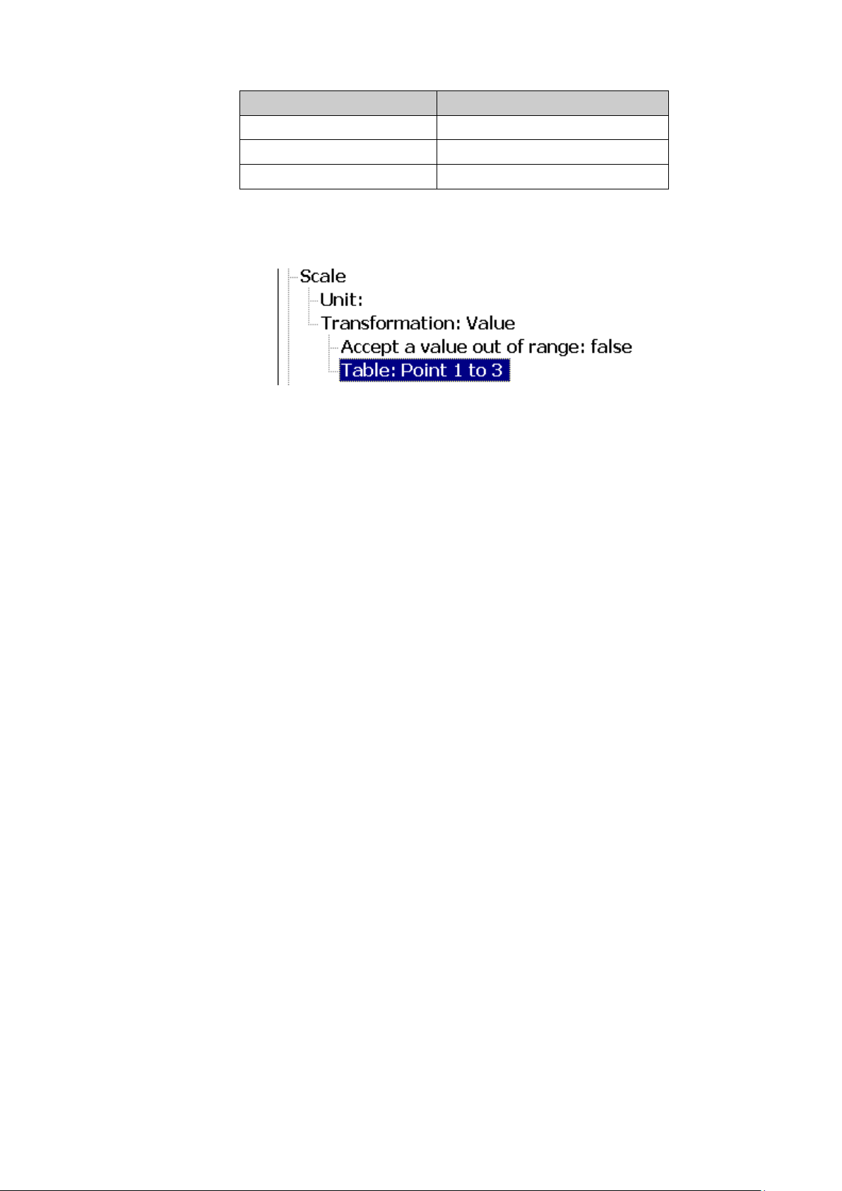
Page 93 of 479
Expressions
Mathematics Functions
ATG(x)
Tan-1(x)
x%y
Remainder of x/y
x^y
xy
5.1.3.6 Scale
The scale is used to do scale the math channel value.
5.1.3.6.1 Unit
The user can define engineering unit for the channel as per the application requirement.
5.1.3.6.2 Transformation
This is mainly used to scale the non-linear process input value. The available options for the
user in transformation menu are disable, value and math channel.
5.1.3.6.2.1 Disable
The transformation function is disable
5.1.3.6.2.2 Value
The transformation table will transform the value of the expression to the same math
channel.
5.1.3.6.2.3 Math Channel
The transformation table will transform the value of the expression to another math
channel.
5.1.3.6.2.3.1 Accept a value out of range
This will allow the user to restrict the maximum value to be displayed as per the value
configured in transformation table.
5.1.3.6.2.3.2 Table
The transformation table can be configured with this menu. The user can configure the table with
maximum of 64 rows with corresponding input and output values.
Page 94
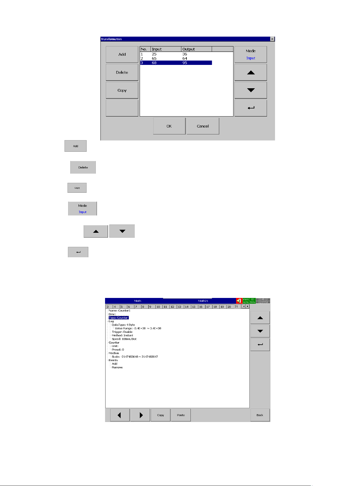
Page 94 of 479
Add
Press “Add” soft key to add a new row into the Transformation table
Delete
Press “Delete” soft key to delete existing row from the Transformation table
Copy
Press to copy existing row in the Transformation table to create a duplicate entry
Mode
Press to toggle between Input and Output entries in the Transformation table
Up & Down
To navigate among rows in the Transformation table
Enter
To change the value of the selected rows.
5.1.3.6.3 Counter
Configure the channel as Counter
Page 95
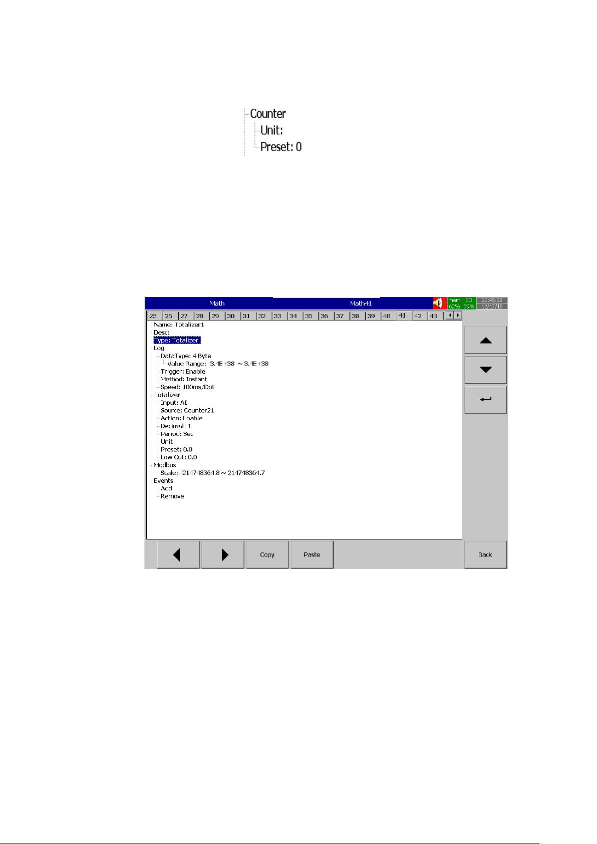
Page 95 of 479
5.1.3.6.3.1 Counter
The counter is used to configure the counter.
5.1.3.6.3.1.1 Unit
Defines the unit of counter
5.1.3.6.3.1.2 Preset Defines the pre-set value for the counter.
5.1.3.6.4 Totalizer
Configure the channel as totalizer
5.1.3.6.4.1 Input
Input type for the Totalizer. Select Analog Input or DI Pulse counter.
5.1.3.6.4.2 Source Select the source for the Totalizer from Analog input/Math/Counter/Totalizer/DI Pulse
counter
5.1.3.6.4.3 Action
Disables or enables the Totalizer
Page 96

Page 96 of 479
5.1.3.6.4.4 Decimal
Defines the decimal point for the Totalizer
5.1.3.6.4.5 Period
Select the period for the totalizer. The available options are Seconds, Minutes, Hours and Days
5.1.3.6.4.6 Unit
Defines the unit of totalizer
5.1.3.6.4.7 Preset
Defines the pre-set value for the Totalizer.
5.1.3.6.4.8 Low Cut
Defines the Low Cut value for the Totalizer. For example If 0.0 is set as Low cut, then, if source
channel AI1 is less than 0.0, the Totalizer value will not go to negative.
5.1.3.7 Modbus
The scaling of the channel value in Modbus communication.
5.1.3.8 Events
Events are frequently used for Alarm purposes. The events can be used to operate digital
outputs (DO), Timer, Totalizer, Counter or Report. There are maximum five events can be added to each
analog input.
Press “Add” to add new event and Press “Remove” to remove selected event
5.1.3.8.1 Type
There are various types of events are available for the user to select for job or alarm purpose.
They are listed as below.
5.1.3.8.1.1 H
It is high event. When the process value is higher than high limit, then the alarm or job
associated with this event is actuated.
Page 97

Page 97 of 479
5.1.3.8.1.2 L
It is low event. When the process value is lower than low limit, then the alarm or job associated
with this event is actuated.
5.1.3.8.1.3 HH
It is high high event. When the process value is higher than high high limit, then the alarm or job
associated with this event is actuated. This is another limit higher than high limit for double warning.
5.1.3.8.1.4 LL
It is low low event. When the process value is lower than low low limit, then the alarm or job
associated with this event is actuated. This is another limit lower than low limit for double warning.
5.1.3.8.1.5 Dev+
It is deviation+ event. This event will be triggered on the positive deviation of process value. The
job or alarm is activated when the process value is deviated by the value higher than set point from the
previous process value.
5.1.3.8.1.6 Dev-
It is deviation- event. This event will be triggered on the negative deviation of process value. The
job or alarm is activated when the process value is deviated by the value lower than set point from the
previous process value.
5.1.3.8.1.7 Error
It is error event. This event will be activated when there is an error on the input of the channel.
5.1.3.8.2 Set point
Set point for the event.
5.1.3.8.2.1 Hysteresis
To avoid the alarm or event been activated too often, Hysteresis value can be defined for the
event trigger set point.
5.1.3.8.2.2 Holding time
To avoid the alarm or event been activated too often, the holding time can be defined for the
event trigger set point. In process sometimes SP is reached but it will go down immediately, this might due
to process instability. To avoid these kind of nuisance situations, the holding time can be used to see that
PV stays at above that SP more than the holding time and then only activate the action for that event. The
range of holding time can be set from 1 min to 60 min.
5.1.3.8.3 Log
The event can be logged as alarm or event. They can be selected from the available options.
They are as below.
5.1.3.8.3.1 Log Alarm
Log the event as Alarm.
5.1.3.8.3.2 Log Alarm (Auto Ack) Log the event as alarms and acknowledge automatically
Page 98
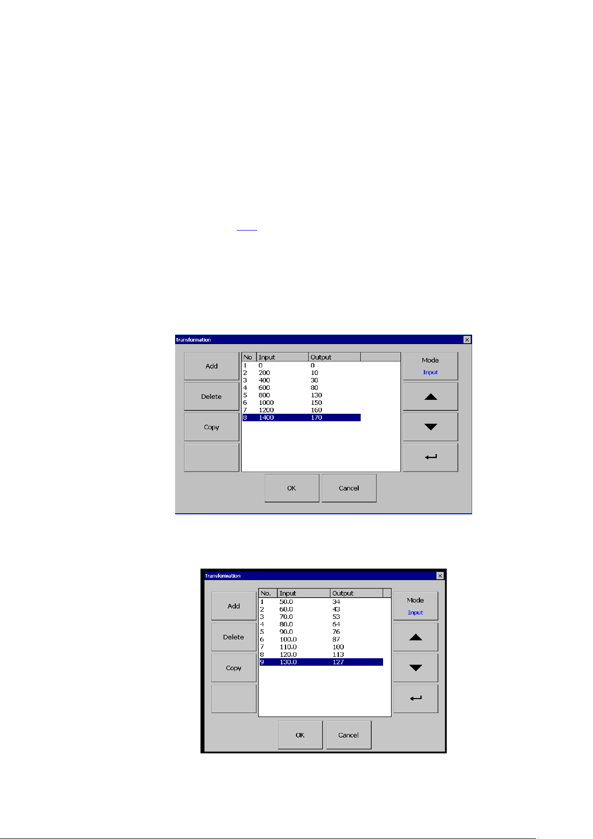
Page 98 of 479
5.1.3.8.3.3 Log Event Log as event
5.1.3.8.4 Job1 & Job2
The job is called as a task to be performed when the event is activated. There are two jobs Job1
and Job2 can be added to perform in any event.
A typical example is to trigger an alarm buzzer in the event of a high temperature. Each
channel can accept five different types of events (or alarms) and each event can create two jobs. Please
note that a job under Event is different from a job perform by Operate key. The job is actuated by an event,
and the Operate is actuated by manual control, no event necessary.
Note: Please refer to the section Jobs for full details about various jobs available
5.1.3.9 Examples for Math Channel Application
5.1.3.9.1 Example 1 with Transformation Table
A chemical tank has a non-linear shape. The level is 0 to 1400 CMS. The Recorder should
display 0 to 170 Tons as per following table
5.1.3.9.2 Example 2 with Transformation Table
The input of 0 to 20mA for pressure 0 to 150 PSIG is required to display as per the below table.
Page 99
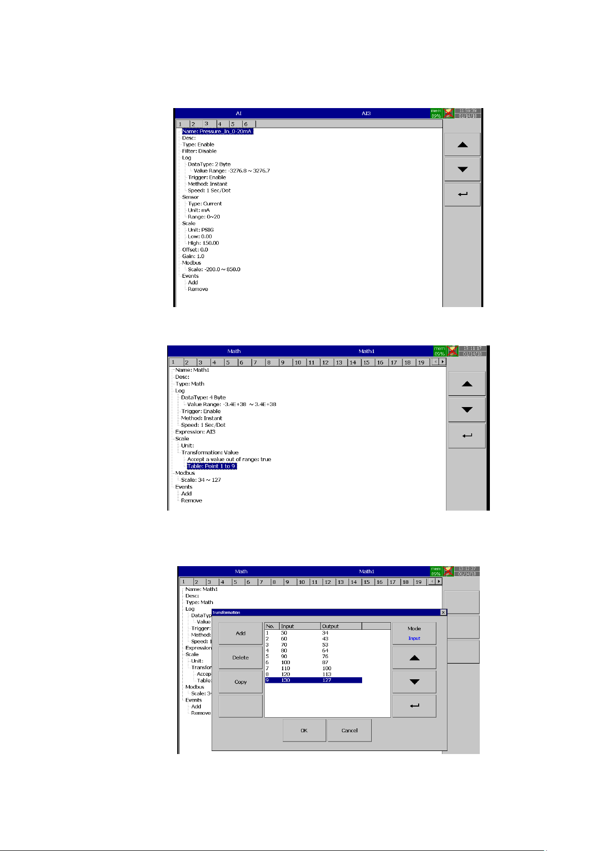
Page 99 of 479
The below steps are required to follow.
1. Configure the AI Channel as per the input configuration.
2. Configure one math channel with the required conversion using transformation table.
3. Configure the Expression with the input channel
4. Add the Transformation table type as values
5. Create the transformation table with the known values.
6. Now the Math channel will show the value as per the table.
Page 100
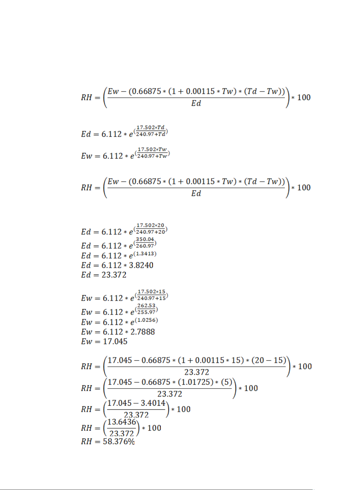
Page 100 of 479
5.1.3.9.3 Relative Humidity Application
The relative humidity can be calculated using Math Channel application. For this we need two
analog inputs with RTD input to measure dry bulb temperature and wet bulb temperature. For this example
the recorder has two analog inputs with RTD input in AI1 to measure dry bulb temperature and AI2 to
measure wet bulb temperature. The below are steps to be followed to calculate the relative humidity.
The relative humidity can be calculated by using the below formulae.
The formulae can be split in to 3 different parts for easier understanding.
1. Calculate Ed with dry-bulb (Td) and wet-bulb (Tw) temperatures using the following equation.
2. Calculate Ew with dry-bulb (Td) and wet-bulb (Tw) temperatures using the following equation.
In the above equations the temperatures units are °C.
3. Calculate Relative Humidity(RH) using the following equation
The units of relative humidity are in %
Example:
Assume that dry-bulb temperature (Td) = 20°C and wet-bulb temperature (Tw) = 15°C.
 Loading...