

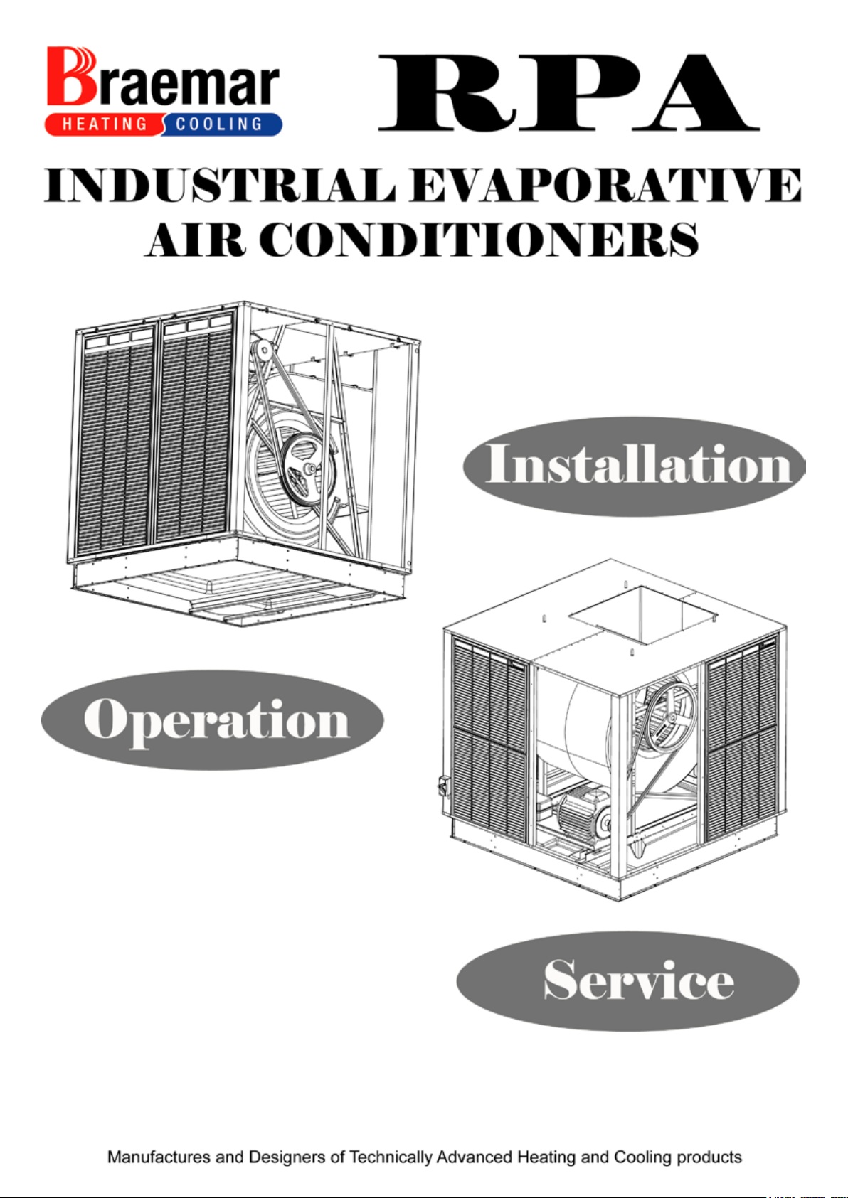
Braemar RPA Series, RPA 1000, RPA 900, RPA 1500, RPA 600 Installation, Operation & Service Manual
...Page 1
January 2014
Page 2

RPA INDUSTRIAL AIR CONDITIONERS
IMPORTANT
As with any product that has moving parts or is subject to wear and tear, it is VERY IMPORTANT
that you maintain the cooler and have it regularly serviced. It is a condition of warranty cover for
your cooler that you comply with all of the maintenance and service requirements set out in the
Owner’s Manual. Compliance with these requirements will prolong the life of your cooler. Further,
it is also a condition of warranty cover that each item in the Maintenance Schedule in the
Owner’s Manual is performed with the frequency indicated, by a qualified, licensed technician,
and that the Maintenance Schedule is properly filled out (ie names, signature, date, and action
taken) when the item is completed. ANY FAILURE TO CARRY OUT THE REQUIRED MAINTE-
NANCE AND SERVICING REQUIREMENTS, AND ANY FAILURE TO PROPERLY FILL OUT
THE MAINTENANCE SCHEDULE, WILL VOID YOUR WARRANTY.
Page 3
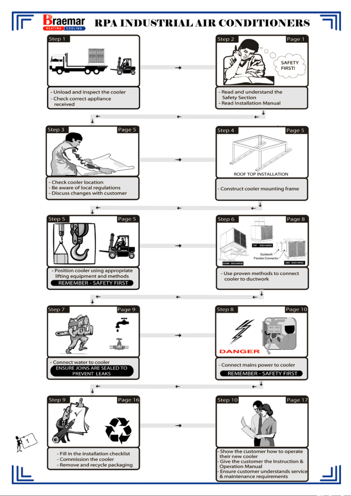
Page 4

RPA INDUSTRIAL AIR CONDITIONERS
TABLE OF CONTENTS
ITEM PAGE
Employer and Employee Responsibilities. 3
General Specifications. 4
Introduction. 5
Location of Air Conditioner. 5
Mounting the Air Conditioner 5
Product Specifications. 6
Flexible Connection. 8
Flexible Connection Kit Instructions 9
Water Supply and Drain Fittings. 11
Electrical Connection. 11
Wiring Diagram - Single Phase 12
Wiring Diagram - Three Phase 13
Variable Pitch Pulley and Belt Tension. 14
Bleed Control. 15
Effective Cooling Requirements 16
Installation Check List. 16
Operating the Air Conditioner. 17
Service Information 17
Service & Maintenance 18
Health Regulations. 18
Lubrication. 18
End of Season Maintenance. 18
Pre Season Maintenance. 19
Replacing the Filter Pads. 19
Trouble Shooting 20
Maintenance Schedule 23
2
Page 5
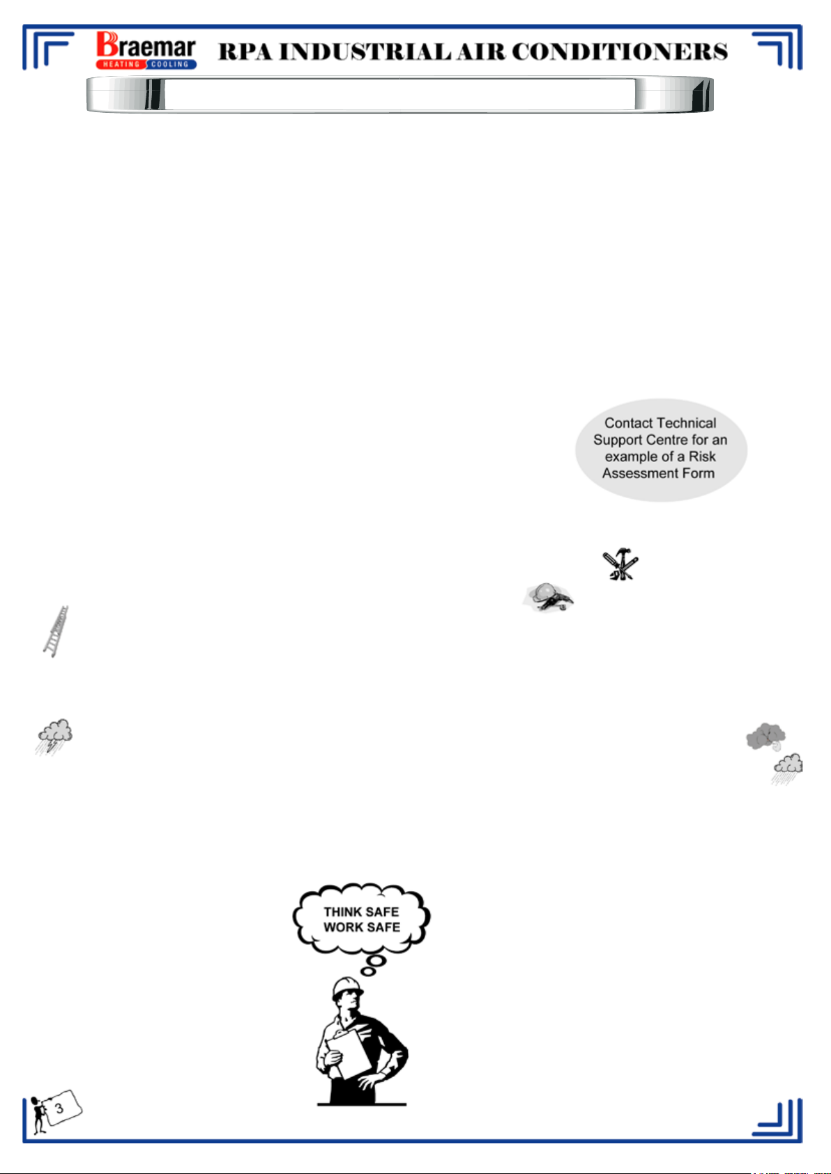
EMPLOYER AND EMPLOYEE RESPONSIBILITIES
The installation and maintenance of evaporative air conditioning units, particularly at height, has the potential to
create Occupational Health and Safety issues for those involved. Installers are advised to ensure they are familiar
with relevant State and Federal legislation, such as Acts, Regulations, approved Codes of Practice and Australian
Standards, which offer practical guidance on these health and safety issues. Compliance with these regulations
will require appropriate work practices, equipment, training and qualification of workers.
Seeley International provides the following information as
a guide to contractors and employees to assist in minimising risk.
Risk Assessment:
A risk assessment of all hazardous tasks is required under legislation. A risk assessment is an essential element
that should be conducted before the commencement of work, to identify and eliminate the risk of falls and other
risks, or to minimise these risks by implementing control measures. This does not need to be a complicated
process - it is a matter of assessing the job to be done and considering what action(s) are necessary so the person
doing the job does not injure themselves.
This should be considered in terms of:
- What are the chances of an incident occurring?
- What could the possible consequences be?
- What can be done to reduce, or better still, eliminate the risk?
Some points to consider when working on or in a roof:
- Check State regulations regarding working at height.
- What is the best and safest access to the roof and working areas?
- What condition is the roof in? Should the roof structure and surface be checked?
- Does the worker have appropriate footwear?
- Are all power cables/extension leads safe and appropriately rated?
Are all ladders, tools and equipment suitable and in good condition?
Where ladders are to be used, is there a firm, stable base for them to stand on? Can they be tied or secured
in some way at the top?
- Is there a roof anchor to attach a harness and lanyard to? If so, instruction should be issued for the use of an
approved harness or only suitably trained people used
- Are all tools and materials being used, prevented from slipping and falling onto a person at ground level? Is
the area below the work area suitably protected to prevent people entering this area?
Does the work schedule take into account weather conditions, allowing for work to be suspended in high
winds, thunder storms/lightning or other types of weather giving wet, slippery surfaces?
- Is there an on-going safety check system of harnesses, ropes, ladders and access/lifting equipment, and
where they exist on roofs, anchor points before the commencement of work?
- Is there a system which prevents employees from working on or in roofs if they are unwell or under the
influence of drugs or alcohol?
- Are there any special conditions to consider i.e. excessive roof pitch, limited ground area, fragile roof,
electrical power lines?
- Use the appropriate lifting equipment.
Page 6
RPA INDUSTRIAL AIR CONDITIONERS
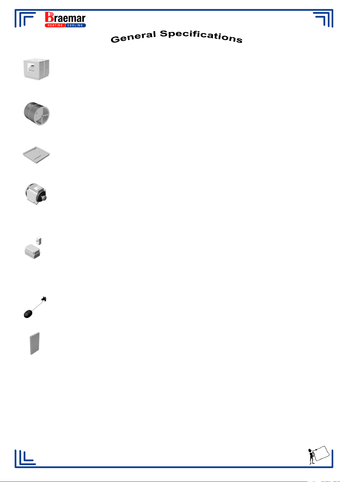
Cabinet.
The cabinet is constructed from marine grade aluminium, incorporating channel section
corner pillars, mounted on a heavy gauge base frame for structural stability. Many
components have been powder coated for extra corrosion protection. Cabinet fasteners are
Stainless steel and Aluminium.
Fan Wheel.
The Fan wheel is a double inlet, multi-blade, forward curve, centrifugal type. Constructed
from galvanised steel, the wheel is statically balanced, The blower shaft is mounted in
plumber blocks with, self aligning, single row ball bearings.
Water Reservoir.
The water reservoir is a one piece Rotational Moulding of Polyethylene, providing a thick
walled, corrosion free component with excellent sound deadening properties.
Fan Motors.
RPA450 to 1500 - 415V 3 Phase TEFC tropic proof induction motor, coated Aluminium or
Cast iron frame, IP55 enclosures to AS1359. Motor current draw can vary depending on
supplier.
RPA400 - 240V Single Phase
Electrical Control.
Three phase starter assembly is pre-wired within the unit and incorporates a dual contactor
assembly for control of high and low speeds, Current overloads are fitted to both high and
low contactors. The enclosure is hose proof to IP55 and incorporates an isolation switch
(RPA400-900 only). RPA1000 to 1500 have an external isolation switch.
Single phase is wired directly to mains.
The wall control switch supplied incorporates the Pump, Fan and High/Low mechanisms.
Water Connection.
Water supply connection is 1/2" BSP, this connects directly to a 1/2" NB standard approved
ball valve.
Filter Pads.
Filter pads are shredded wood wool fibre or Chillcel® with a minimum operating saturation
efficiency of 80%. All models incorporate a full ABS Louvre (UV stabilised) to enhance the
appearance of the pad and to prevent water splash.
Special Features. Bleed off adjustment is by an external valve located at the
corner pillar. A mains isolator is provided. Flexible Connectors are standard on RPA400 to
900 - (RPA1000 to 1500 optional).
Unit Rating.
Units are factory set to run (free discharge) at the motor rated current, unless operating
conditions are specified. Motor ratings, Pulley and Belt sizes are nominal, and may vary
slightly due to manufacturing tolerances. Larger & Smaller motor pulleys and belts are
available on request.
It is the policy of Seeley International to introduce continual product improvement. Accordingly, specifications are subject to
change without notice. Please consult with your dealer to confirm the specifications of the model selected.
Manufacturers and Designers of Technically Advanced Quali
ty Heating and Cooling Products
4
Page 7
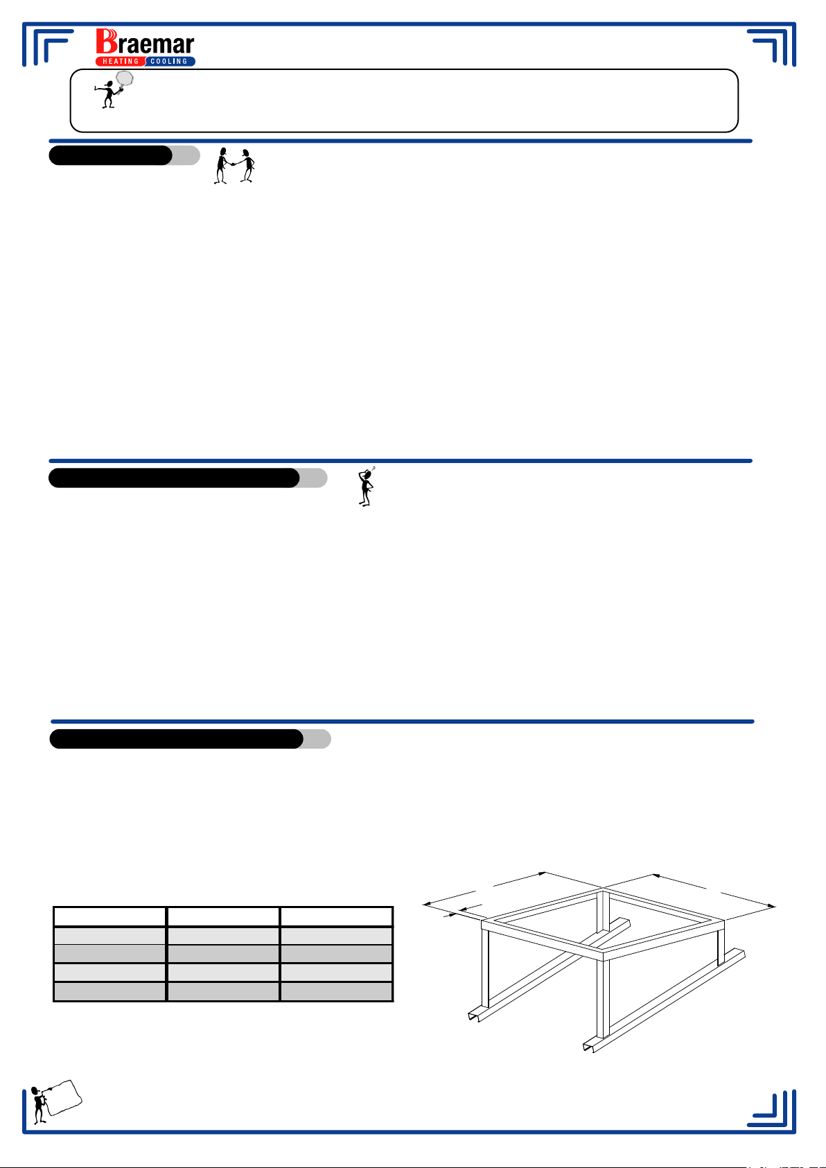
RPA INDUSTRIAL AIR CONDITIONERS
Model Dimension A Dimension B
RPA 400-500 1055 30 min
Important!
Installation must be in accordance with Municipal building Regulations,
Relevant Electrical Wiring Regulations, and any other relevant Codes and Regulations
Introduction.
All Braemar air conditioners are run and electrically tested at the factory.
Subject to normal handling during storage, transit, installation and operation, they will provide
years of economical air conditioning with the minimum of service and maintenance.
All Braemar air conditioners are designed for a range of installations and are readily adaptable to
the following applications.
a. Through wall or window mounting for direct discharge through the appropriate air
diffusion equipment
b. Wall mounting for plenum chamber diffusion.
c. Roof (all models), ground or wall mounting for connection of multiple outlet duct systems.
d. Roof (all models), ground or wall mounting for connection to a duct system for central
plenum air diffusion.
Location of Air Conditioner.
To ensure only fresh air flows through the filter pads. locate the cooler away from chimneys,
exhaust/extractor flues, heater flue pipes and sewer vents.
Check your local building code for the minimum distances in your area.
Allow adequate access to and around the cooler for maintenance. Provision must be made for
access to electricity, water supply and drains
Thoroughly seal all roof penetrations, this will ensure storm water cannot enter the building as a
result of the installation
Unit Mounting Guidelines.
Mounting the RPA unit. - A level platform is required for all units and must be strong enough to
support the unit under operating and prevailing conditions.
RPA ROOF MOUNTED TYPE DETAILS
A
B
A
RPA 1000-1500 1940 30 min
RPA 700-900 1480 30 min
RPA 600 1330 30 min
5
Typical Detail
Page 8
RPA INDUSTRIAL AIR CONDITIONERS
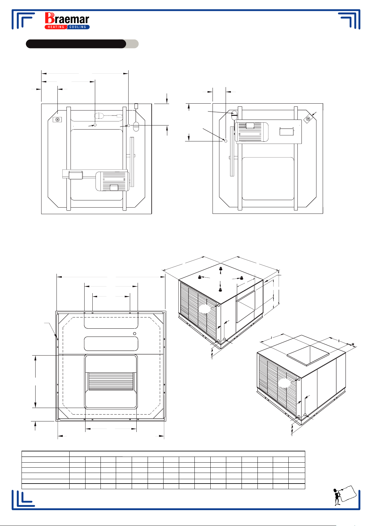
Product Specification.
Services Layout RPA400 - RPA600
+
M 10
-
DRAIN
400/500
BLOWER ASSEMBLY
CONTROL
BOX
PLAN VIEW
500 Only
DRAIN
600 Only
MOTOR
+
M 10
-
PUMP
+
M 10
-
-
+
L 10
Services Layout RPA700 - RPA900
+
M 10
-
Float
Drain
-
+
RPA700/900
L 10
MOTOR
BLOWER ASSEMBLY
PLAN VIEW
CONTROL
BOX
Pump
Mounting Detail RPA400 - RPA900
C
D
E
RPA 400/500 only
ALL SLOTS
16 x 9.5
I
K
J
P = MOUNT HOLE CENTRES
B
LIFTING EYES
OPTIONAL
ELEC
ENTRY
F
ELEC
ENTRY
G
WATER
INLET
TOP DISCHARGE
B
ELEC
J
ENTRY
A
I
SIDE DISCHARGE
N
J
ELEC
ENTRY
F
ELEC
ENTRY
G
WATER
INLET
I
H
MODEL
A
B
C
RPA400 / 500*
RPA600
RPA700 / 900
1170
1370
1650
1145
1375
1520
1050
1325
1475
D
682
700
796
*RPA500 AVAILABLE IN DOWN DISCHARGE ONLY
E
560F150
140
295
215
215
215
G
H
I
J
K
L
M
N
50
115
62
610
660
780
610
660
760
100
200
150
200
300
415
575
1135
185
490
550
650
P
1032
1307
1457
6
DIMENSIONS
Page 9
RPA INDUSTRIAL AIR CONDITIONERS
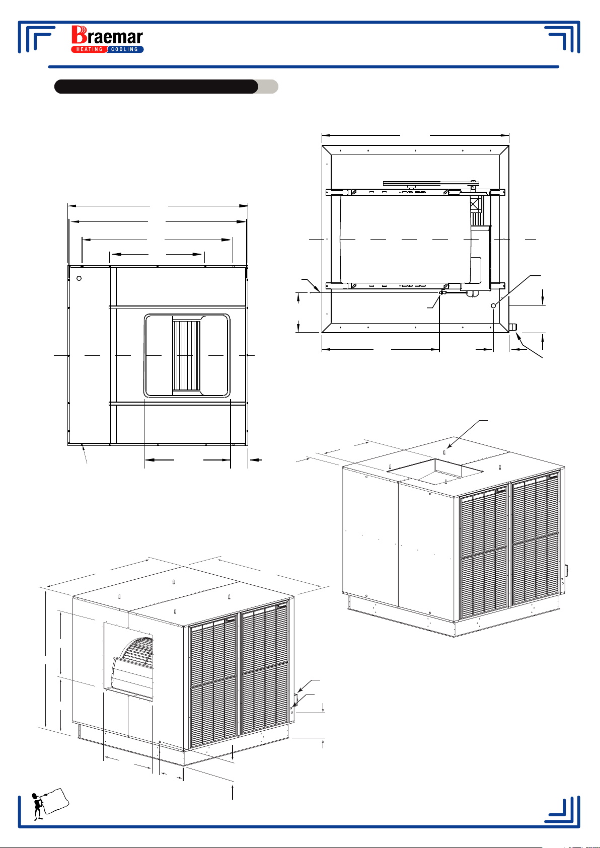
Product Specifications cont.
Mounting Detail RPA1000 - RPA1800 Services Detail RPA1000 - RPA1800
2030 TYP
1937
Distance between mount holes centres
1917
1625
1025
WATER
INLET
MOTOR
CONTROL BOX
DRAIN VALVE
LOCATION
MOUNT HOLES
16 X 9.5
2030
890 SQ
230
2030
230
430
FLOAT VALVE
1275
200 ±10
Up to 4 pumps located behind
motor platform
890
290 ±10
ISOLATION
SWITCH
Lifting Eyes (Optional Extra)
1904
890
TOP DISCHARGE
Isolating switch
Bleed Adjustment Tap
776
Water Inlet Point
350
Water
Inlet
890
430
7
SIDE DISCHARGE
260
Units with 8 Pads Only
Page 10
RPA INDUSTRIAL AIR CONDITIONERS
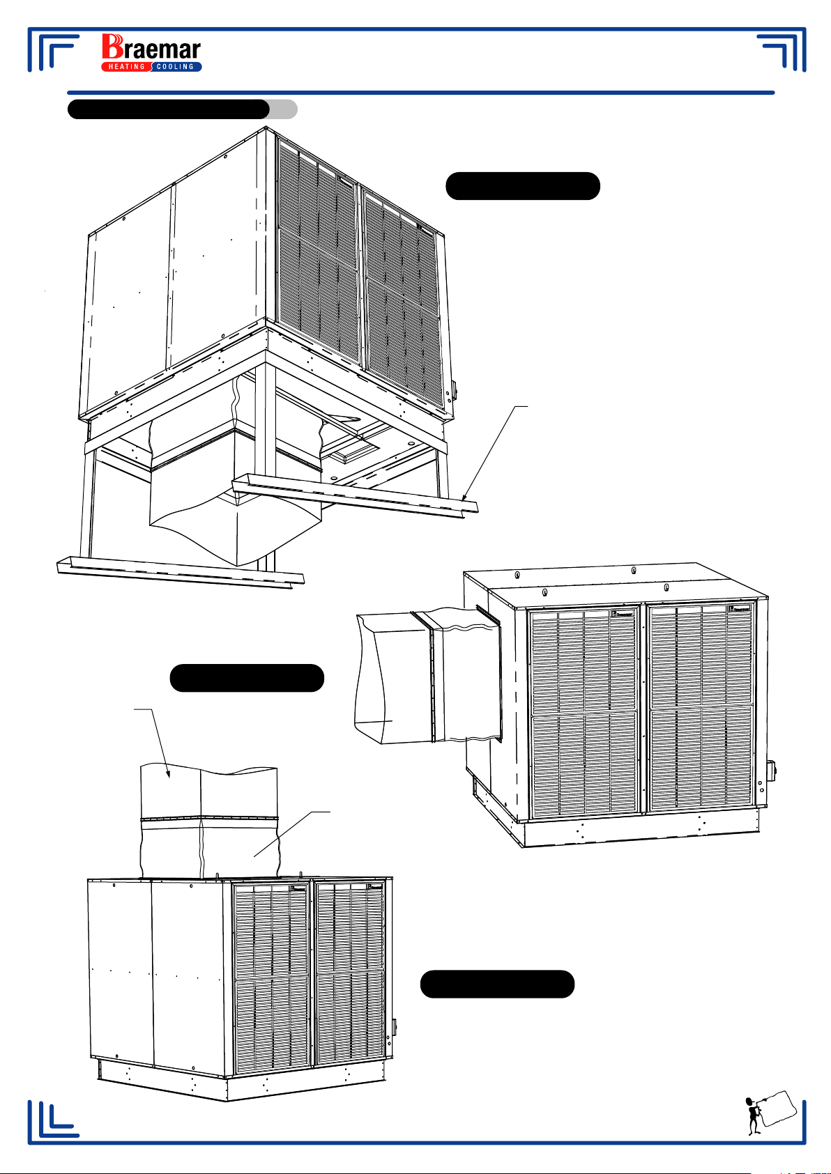
Flexible Connections.
RPA1000 to 1800
DOWN DISCHARGE
Mounting Frame
Ductwork
SIDE DISCHARGE
Flexible Connector.
TOP DISCHARGE
8
Page 11
RPA INDUSTRIAL AIR CONDITIONERS
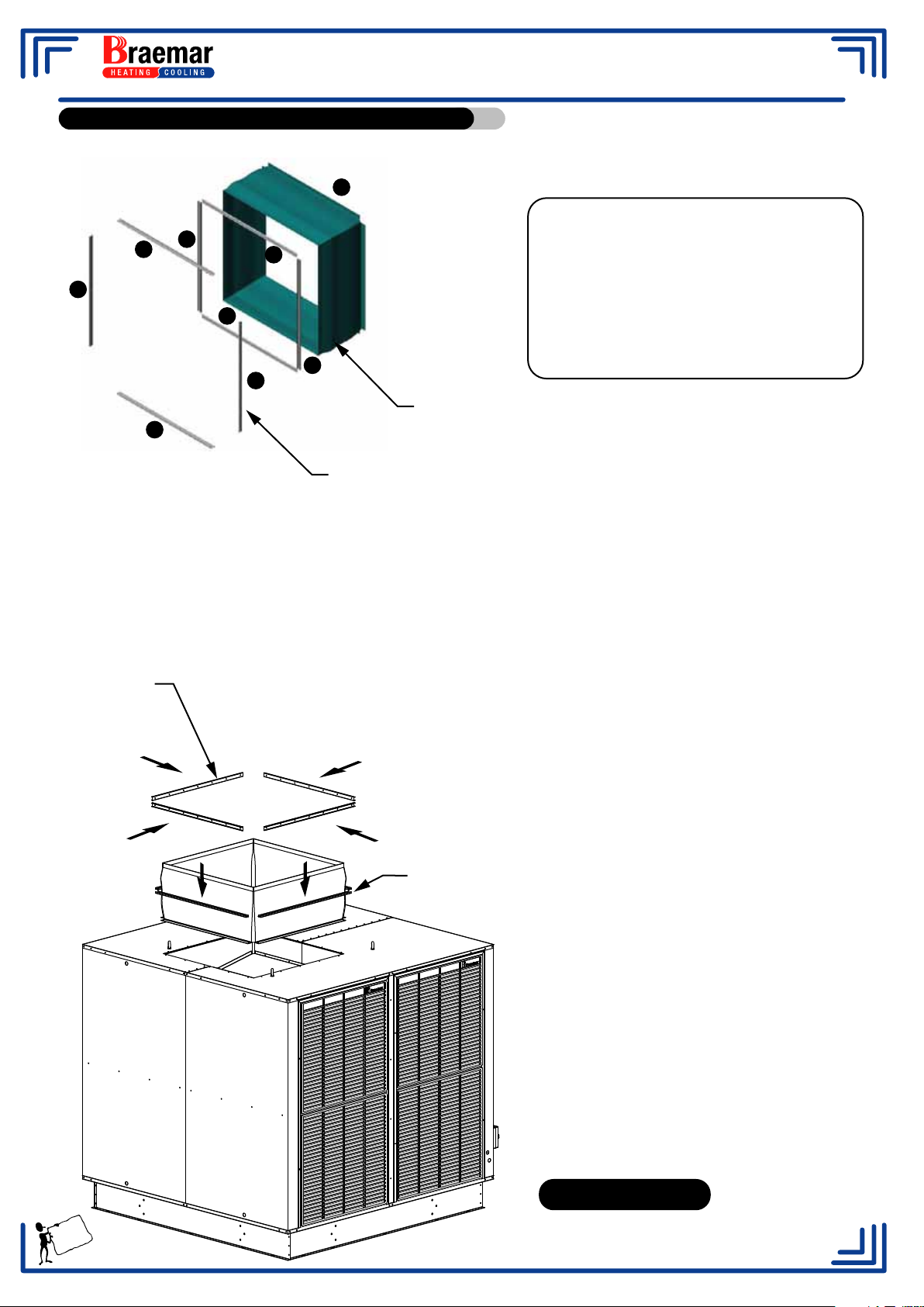
Flexible Connection....Fitting Instructions.
J
F
D
C
G
E
RPA1000 to RPA1800 Series
FLEXIBLE CONNECTOR KIT - 096582
CONTENTS
DESCRIPTION STOCK QTY
CODE
1. Flexible Connector 609645 1
2. Channel 609423 8
3. Rivet - 5/32" Alum FAS204 60
A
H
4. Instruction Sheet 621920 1
Flexible Connector
B
Channel
FITTING INSTRUCTIONS
The flexible connector on the RPA1000 to 1500 has not been fitted at the factory. It is intended to be fitted
on site to allow for better alignment to the ductwork.
1. Position the flexible connector (part J) with the seam to the bottom. The corners of the skirt will need to
be slit approximately 20mm to prevent bulging at the corners.
2. The metal channels A to H fit outside the skirt.
Channels A to D
3. Fit channel (part G) using the rivets supplied, starting from the centre and
working towards the ends. The skirt must be tucked between the
channel and unit before securing. The bottom edge of the channel
is intended to be level with the edge of the opening in the
cooler. This is not essential and may be adjusted to suit
your installation.
4. Secure channels E to H in the same
manner as above.
Channels E to H
5. Install ductwork between 250mm
and 320mm from unit. Secure
remaining channels A to D to side of
duct with rivets supplied.
Seal with Silicone after completion.
TOP DISCHARGE
9
Page 12
RPA INDUSTRIAL AIR CONDITIONERS
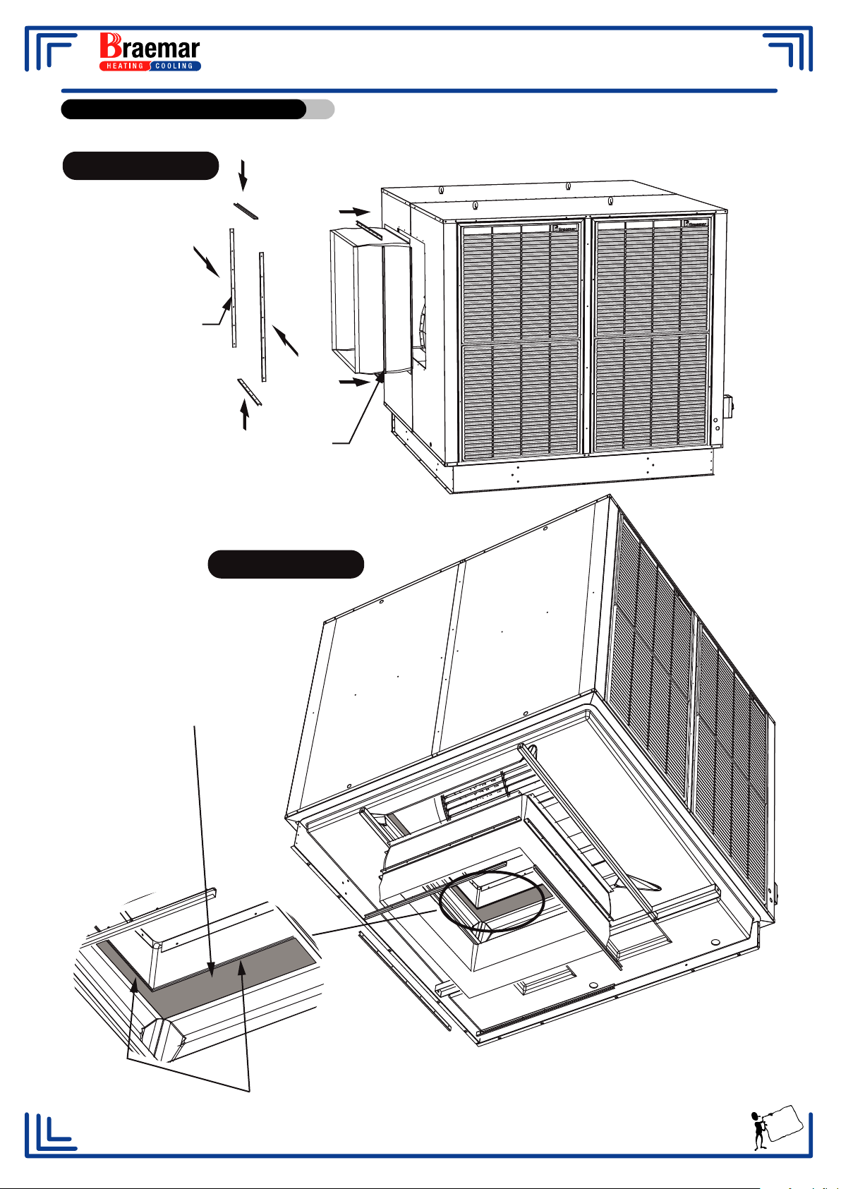
Fitting Instructions cont.
SIDE DIS
C
hannel
s
A
CHAR
t
o
GE
D
C
hannel
s
E
t
RPA1000 to RPA1800 Series
o
H
DOWN DISCHAR
Note: On down discharge units,
secure flexible connector to each
of the edges (4) where the tank
and outlet meet as highlighted
by the shaded section below.
GE
Tank & Outlet Edge
Refer Diagrams on page 8
for nished assembly of
Flexible Connector and Ductwork
10
Page 13
RPA INDUSTRIAL AIR CONDITIONERS
Water Supply and Drain Fittings.
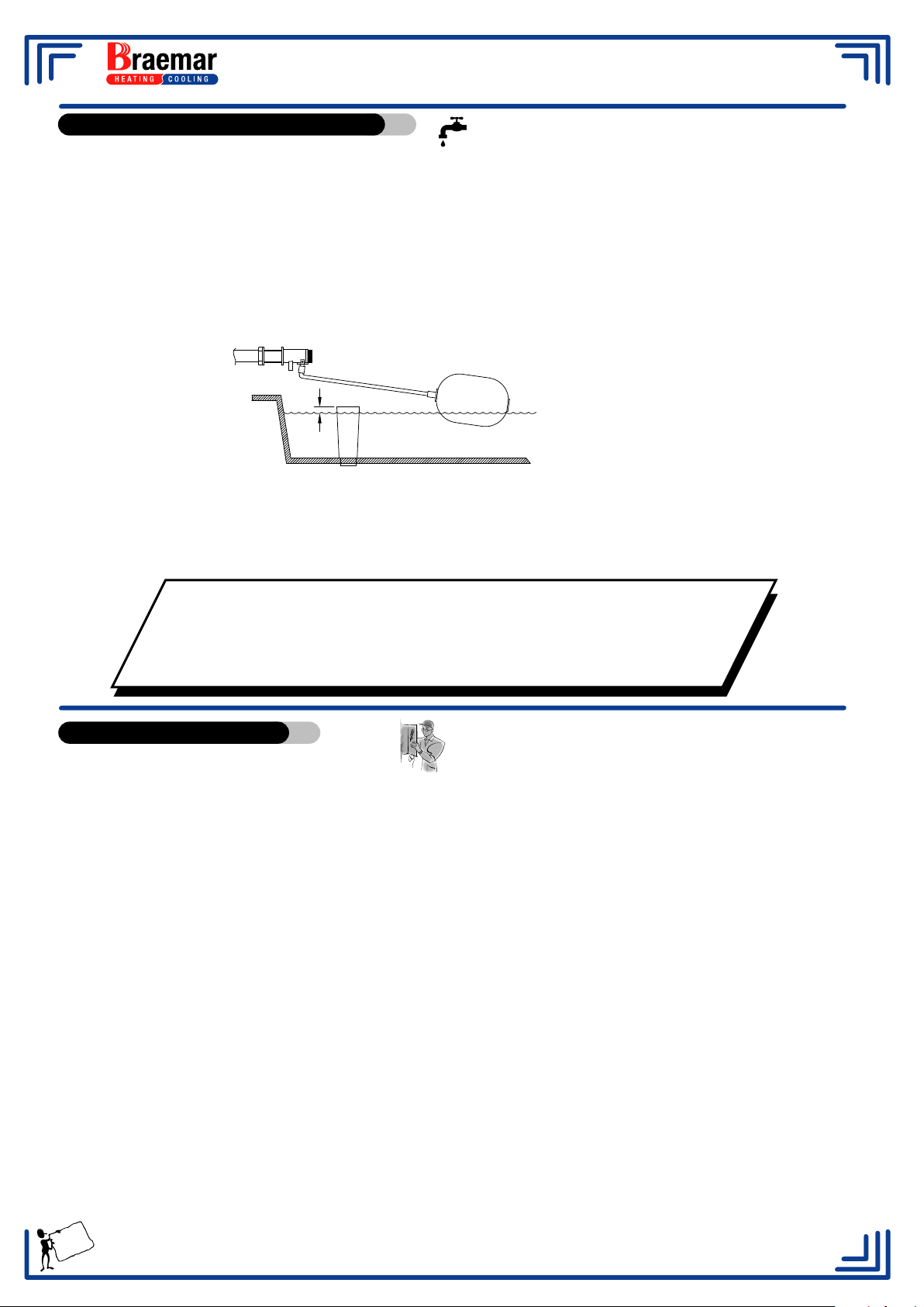
Mains Water connection is made to the float valve fitted in the reservoir. The mains
water supply to and inside the unit should be made with the appropriate copper pipe and
fittings. A stopcock must be fitted outside the unit.
The float valve must be set to maintain the reservoir water level about 10 mm below the
overflow level.
An overflow stand pipe is supplied with the unit and must be fitted to the hole
provided in the water reservoir. RPA400 - 1800 have a 40 mm drain/overflow supplied as
standard.
10 Max
Drain Valves
When fitting drain valves, other than the Seeley type, the overflow assembly must not be
removed. Fit the drain valve in a separate location in a new hole.
When fitting the Seeley Drain Valve, use the existing overflow assembly hole.
NOTE: Flush the mains water supply before connection to the unit
to remove any foreign matter which may foul the float valve seat.
Ensure that the drain hole in the reservoir and any penetrations
through the roof are adequately sealed with an approved sealant.
Electrical Connection.
Connection to the Electricity Supply
It is a requirement of Seeley International that all coolers be wired with a dedicated circuit to the
distribution board adhering to Local and National wiring standards. Ensure that the power supply
corresponds to the rating indicated on the serial plate.
RPA coolers ( RPA400 - 900 ) have a 25mm diameter knockout hole at the top and bottom of the
front panel, use one of these holes for the conduit entry. Wire the unit in accordance with the
wiring diagram supplied and the local supply regulations.
RPA coolers ( 1000 - 1800 ) have a separate mains isolator located on a corner pillar. Wire the
mains power to the isolator.
Mounting the Control Switch - Mount the control switch in the most desirable location.
Two Speed Single & Three Phase Units
Controls for two speed air conditioners are 240 Volt Clipsal switch plate pattern.
No adjustment of minimum or maximum speed is necessary.
Control circuit wiring is via a 240V 5 wire system.
Wire the unit in accordance with the wiring diagram supplied and the local supply regulations.
11
Page 14
RPA INDUSTRIAL AIR CONDITIONERS
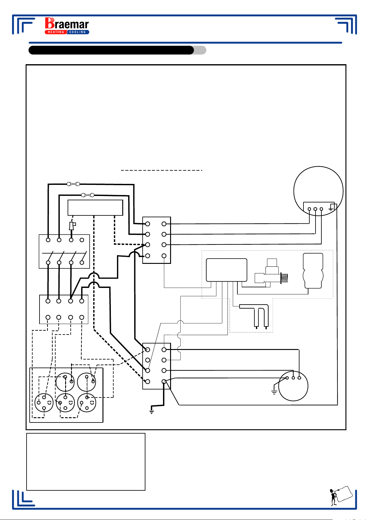
Wiring Diagram - Two Speed Single Phase.
TWO SPEED SINGLE PHASE WIRING DIAGRAM
107196 ISOLATION BOX
THESE WIRING INSTRUCTIONS ARE FOR UNITS MADE FROM JANUARY 2006
WIRING INSTRUCTIONS
1. THE INCOMING MAINS POWER MUST BE TAKEN DIRECTLY TO THE COOLER.
2. 5 WIRES ARE REQUIRED BETWEEN THE COOLER AND THE WALL SWITCH.
3. FOR DRAIN KIT 077444 WIRING INSTRUCTIONS SEE MANUAL SUPPLIED IN KIT OR VISIT
OUR WEB SITE www.braemar.com.au
ALL FIELD WIRING IS SHOWN AS
FUSE
FUSE
BROWN
BROWN
2 SPEED
FAN MOTOR
8 6 4 2
4 POLE ISOLATOR
7 5 3 1
RED
WHITE
9 10 11 12
FAN LOW
FAN HIGH
NEON1
1
C
2
ACTIVE
MAINS IN
CONNECTOR
BROWN
PUMP
NEON2
1
2
LO HI C
NA E
LOW
HIGH
COMMON
Solenoid
Drain
Valve
BROWN
BLUE
8
7
6
5
DRAIN KIT COMPONENTS
Electronics
enclosure
BROWN
ORANGE
Sensor
WHITE
BROWN
*
4
3
2
1
1
2
EARTH *
BLUE
BLUE
BROWN
EARTH
E NA
PUMP
EARTH
LO/HI FAN COOL
(VIEWED FROM REAR)
Drain Valve connections are as follows;
Brown* wire from pump to terminal 3
Brown wire to terminal 5
Blue wire to terminal 4
White wire to terminal 2
Orange wire to terminal 3
12
Page 15
RPA INDUSTRIAL AIR CONDITIONERS
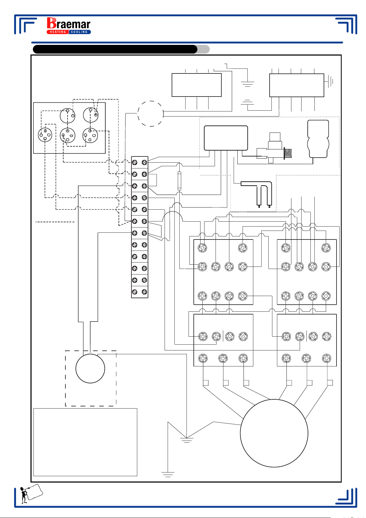
Wiring Diagram - Two Speed Three Phase.
3 PHASE
WIRING DIAGRAM
WALL SWITCH
Neon1
1
C
Lo/Hi
FAN LO
FIELD WIRING
C
2
FAN HI
Neon2
Fan
1
2
ACTIVE
NEUTRAL
TERMINAL
1
C
2
Cool
PUMP
BROWN
BLUE
1
2
3
4
5
6
7
8
9
TO
POINT 6
BLACK
*RED
RED
L1 L2 L3 N E
ISOLATING
SWITCH
RPB600-1000
RPA450-900
RED
WHITE
BROWN
ORANGE
3AG 250V
5A FUSE
WHITE
BLUE
BLACK
A1
MAINS IN
E N L1 L2 L3
ISOLATING
SWITCH
TO EARTH
POINT 1
BLUE
BLACK (Neutral)
RPB1200-1800
RPA1000-1800
RED
DRAIN KIT COMPONENTS
Electronics
enclosure
Solenoid
To Isolating
Sensor
BLUE
WHITE
BLACK
GREY
A2
GREY
RED
Switch
RED
A1 A2
WHITE
WHITE
BLUE
Drain
Valve
BLUE
BROWN
BLUE
WATER
PUMP
WATER PUMP
CONNECTION
ALL MODELS
*Link wire removed when drain
Valve is installed.
Drain Valve connections are as
follows;
Brown wire to terminal 1
Blue wire to terminal 7
Orangewire to terminal 2
White wire to terminal 3
EARTH
10
11
12
GREY
GREY
1 L1 3 L2 5 L3 21 NC
CONTACTOR
2 T1 4 T2 6 T3 22 NC
GREY
OVERLOAD OVERLOAD
NC NO
95 96 97 98
2 T1 4 T2 6 T3
EARTH
GREY
GREY
12 3 4 5
GREY
1 L1 3 L2 5 L3 21 NC
CONTACTOR
2 T1
4 T2
GREY
NC NO
95 96 97 98
2 T1 4 T2 6 T3
GREY
GREY
6 T3 22 NC
GREY
6
MOTOR
EARTH
EARTH
POINT 1
(TO MOTOR PLATFORM)
13
Page 16
RPA INDUSTRIAL AIR CONDITIONERS
Variable Pitch Pulley and Belt Tension.
Models RPA400 - 900 are fitted with a variable pitch pulley so that the full potential of the motor
can be utilised. The pulley is set at the factory to approximate the full motor load with the unit at
free delivery. When installed and operating against system resistance, (with doors and windows
open) adjustment may be made to the pulley in order that all the available power is utilised.
Models RPA1000 - RPA1300 are supplied with variable pitch pulleys. Fixed pulleys are fitted to
the RPA1400 - RPA1800.
Method of Variable Pulley Adjustment.
1. Ensure installation is complete and that all registers are set to their maximum openings.
2. Operate the unit and allow the motor to warm up ( 10 - 15 minutes ).
3. Measure the current being drawn by the motor on high speed.
4. Compare the rated current shown on the rating plate, to the measured current. If the current is
significantly above or below the rated current, pulley adjustment may be made as follows.
5. Isolate unit and remove the “ V “ belt/s. Loosen the grub screws in the flange of the pulley.
Screw pulley flange in to increase the blower speed and amperage, and screw it out to
decrease blower speed and amperage.
Re-tighten the grub screws in the flange evenly.
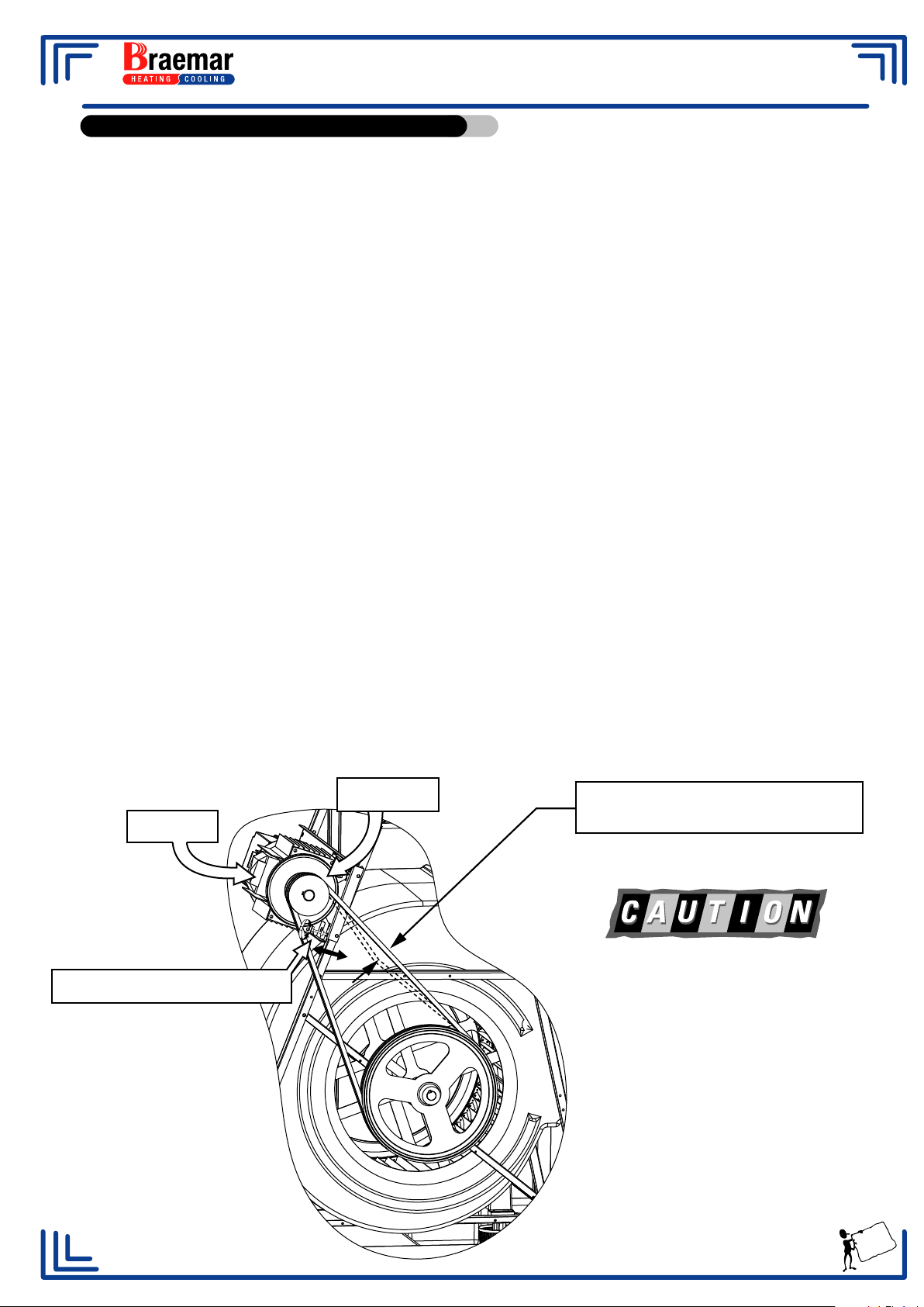
6. Adjust the pulley as shown in figure below.
7. It will be necessary to adjust the belt tension by using the jacking screws after any pulley
adjustment has been made.
8. A new drive can be tightened initially 50% more than normal to allow for the drop in tension
during run-in.
Motor / Pulley arrangement for models RPA400 TO RPA600
MOTOR
BELT TENSION SCREW
PULLEY
1.6mm/100mm SPAN @ 2.0kg
BELT DEFLECTION FORCE
If turning pulley counter clockwise to reduce
blower speed, ensure that the V section is not
opened far enough to allow the belt to ride on
the threaded part of pulley, as this will cause
damage to the belt.
Too great a belt tension will increase
motor load, and shorten belt and bearing
life.
Too loose a belt will cause belt slippage
and excessive belt and pulley wear.
14
Page 17
RPA INDUSTRIAL AIR CONDITIONERS
Variable Pitch Pulley and Belt Tension (cont.)
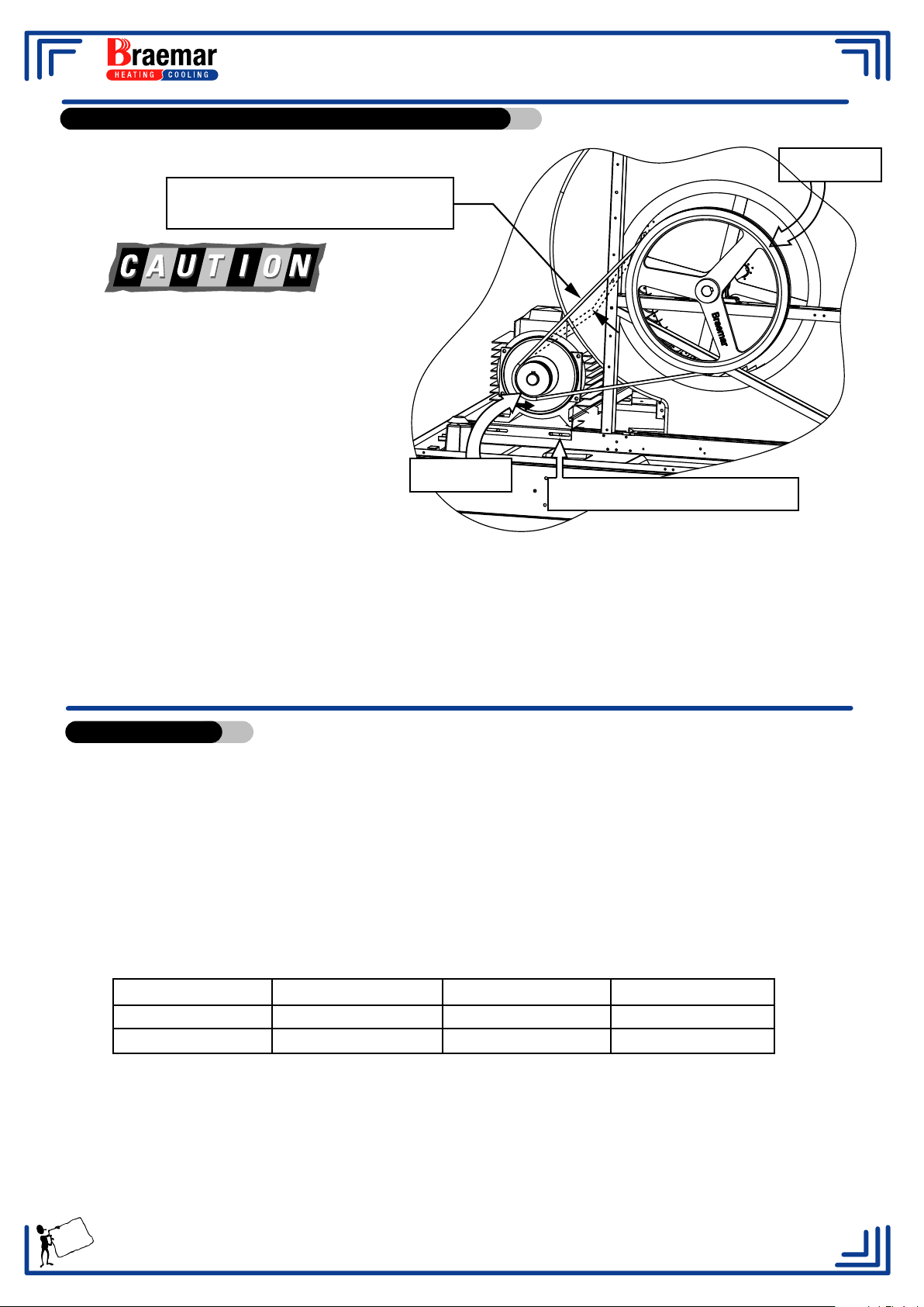
Motor / Pulley arrangement for models RPA700 TO RPA1500
1.6mm/100mm SPAN @ 2.0kg
BELT DEFLECTION FORCE
If turning pulley counter clockwise to reduce
blower speed, be sure that the V section is not
opened far enough to allow the belt to ride on
the threaded part of pulley, as this will cause
damage to the belt.
Too great a belt tension will increase
motor load, and shorten belt and bearing life.
Too loose a belt will cause belt slippage and
excessive belt and pulley wear.
PULLEY
PULLEY
BELT TENSION SCREWS
Check the Full Load Amps
After any adjustments to belt tension, the maximum full load current must be checked
to ensure it is within the rating specified on the serial plate. If the amps are not within
rating, make adjustments to the motor pulley as described in this section. Only units
with a variable pitch pulley can be adjusted, other units will need to have the
installation checked.
Check that the full load current on high and low speed is within the motor rating.
Bleed Control.
To reduce the accumulation of salts and minerals in the recirculated water it is essential to bleed a
certain amount of water to waste. Increased flow of make up water reduces the salt content.
The bleed rate will vary with the water supply quality, but should initially be set to the minimum
recommended bleed rates as set out in the chart below. The bleed line from the flow and bleed
controller in the pump delivery line, inside the unit , must be suspended through the overflow
stand pipe, or into the side of the optional drain valve. Connect suitable pipe work to bottom
thread of the drain bush so that water drains directly to waste.
Table 1 Recommended Minimum Bleed Rates (LPH)
RPA400 11 RPA600 16 RPA1000 26 RPA1400 36
RPA450 12 RPA700 18 RPA1200 31 RPA1500 39
RPA500 13 RPA900 24 RPA1300 34
Location of Bleed Control.
The bleed control tap is located externally on a corner pillar.
Adjustment to the bleed rate is made by turning the black/red tap control to the desired setting.
Check the bleed rate by running into a graduated container for a set time, say 10 minutes.
Build up of salt deposits in the pads or the tank indicates that the bleed rate is inadequate.
Increase the rate where necessary.
15
Page 18
RPA INDUSTRIAL AIR CONDITIONERS
Effective Cooling Requirements.
To provide efficient cooling or ventilation your air conditioner must be operated with sufficient
exhaust openings in the form of doors, windows, or other vents.
One square metre of open area is the minimum requirement for every 3000 m3/hr (830 l/s) of air
delivery. ( ie. a 6000 m3/hr (1660 l/s) air conditioner requires a minimum of 2 square metres of
open exhaust areas ).
For optimum cooling performance, windows opposite the prevailing wind conditions should be
opened. The cool filtered air entering the building will flow toward the exhaust openings. Doors
and windows should be set according to the airflow pattern desired.
Air should never be recirculated back through the air conditioner.
When the design of the building or prevailing winds prevent effective airflow, consideration must
be given to the use of some form of exhaust extraction device.
Installation Check List.
TO BE COMPLETED BY
THE COMMISSIONING AGENT
1. Unit level on mounting platform / dropper.
2. Unit correctly flashed to prevent water damage.
3. " V “ belt alignment and tension checked.
4. Unit wired in accordance with regulations and operating correctly.
5. Water main flushed before connection to unit.
6. Float valve set correctly.
7. Water flow adequate to all pads.
8. Bleed rate set and bleed hose positioned in overflow.
9. Filter pad frames uniformly packed (woodwool pads only).
10. Water distribution through pads uniform.
11. Control switch tested.
Pump only running.
High Speed Fan only.
High Speed Fan and Pump running.
Low Speed start-up.
Low Speed running .
12. Unit tested for maximum amperage.
13. Air flow from duct outlets correctly set.
14. Adequate exhaust openings provided.
15. OWNER INSTRUCTED IN METHODS OF OPERATION.
16. OWNER ADVISED ON MAINTENANCE SERVICING REQUIREMENT.
17. OWNER PRESENTED WITH OPERATING INSTRUCTIONS.
INSTALLATION CHECKED / COMMISSIONED AND APPROVED BY
Agent ..............................................DATE ........ / ........ / ..........
16
Page 19
RPA INDUSTRIAL AIR CONDITIONERS
Operating the Air Conditioner
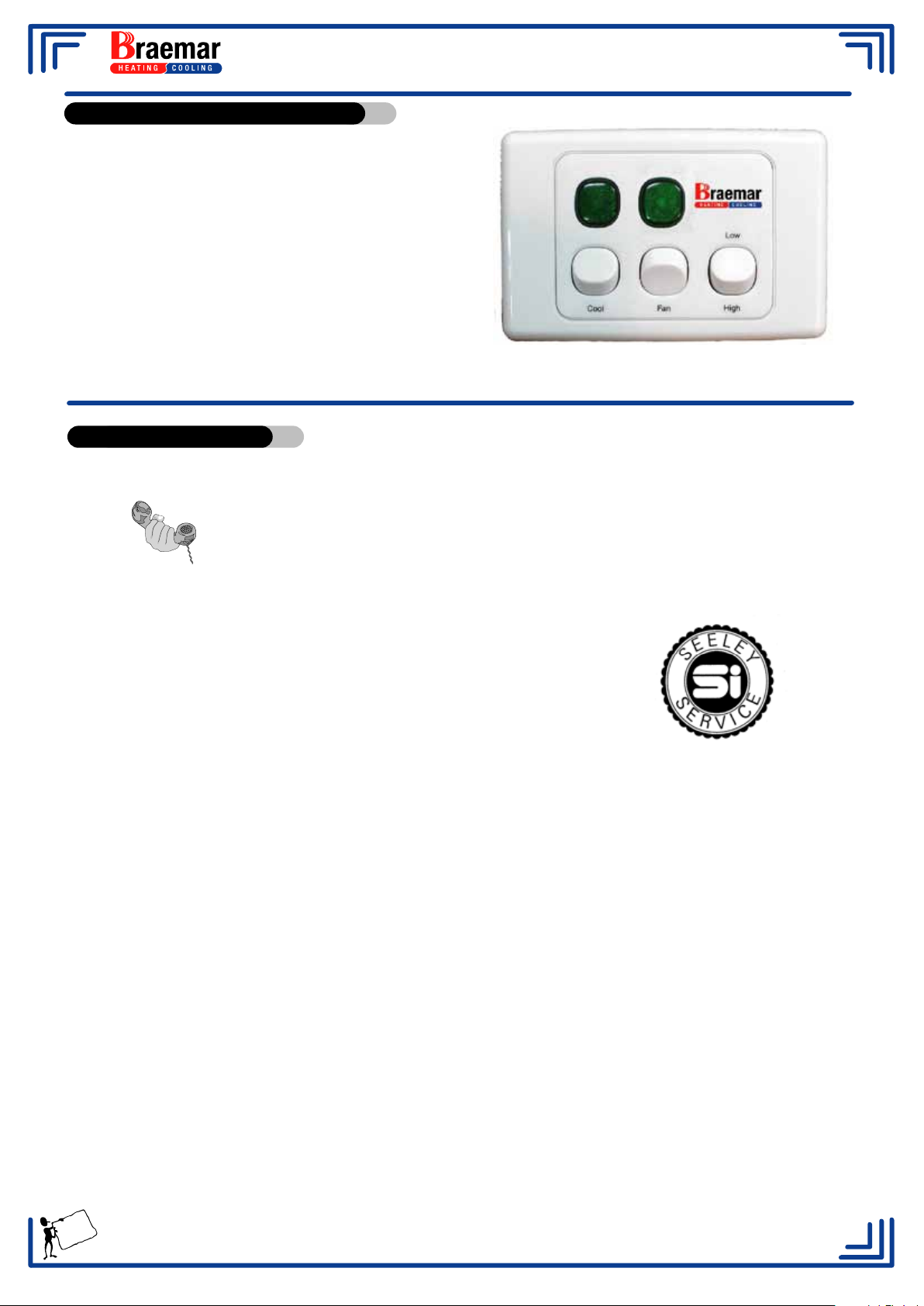
- Turn on the water at the source and ensure
that any shut off valve is open.
- Turn on the electrical supply and the mains
isolator at the air conditioner.
- Wait for the tank to fill with water.
- Turn on the pump by switching
the Cool switch on the wall control to Cool.
- Wait 2 - 5 minutes for the pads to saturate
with water.
- Select either High or Low fan speed.
- Turn on the fan by switching the Fan switch to ON.
Service Information.
Should you consider that your Braemar air conditioner requires service,
you should contact your local Braemar Dealer/Service Agent.
For Service please phone
1300 650 644
quote the unit Model number and Serial number as shown below.
Model No................................... Serial No..................................
For your future reference:
Air conditioner purchased from........................................................................
Air conditioner purchase date ...... / ...... / ....... Phone No ..................
Air conditioner installed by..............................................................................
Air conditioner installation date ...... / ...... / ....... Phone No .................
17
Page 20
RPA INDUSTRIAL AIR CONDITIONERS
Service & Maintenance
REGULAR MAINTENANCE IS ESSENTIAL FOR MAXIMUM EFFICIENCY
To ensure that your Braemar Evaporative Air conditioner remains in first class working
condition for many years, it should be thoroughly serviced four (4) times a year. Service
schedules should include a service at the end of the summer season and prior to the
commencement of the next summer season.
. Health Regulations.
Please note that some State Regulations require that Evaporative Air Conditioners
used for Commercial purposes must be serviced at Three ( 3 ) Monthly Intervals.
Owners of Commercial Air Conditioners should contact the Health Authority in their State for
servicing guidelines.
11. Lubrication - All models.
Bearings on electric motors and water pumps are sealed for life and do not require
lubrication. The same applies to the fan shaft bearings on the RPA400-RPA900.
RPA1000 - RPA1500 fan shafts are fitted with plumber blocks with grease nipples, lubricate
at regular intervals, depending on frequency of use.
. End of Season Maintenance.
Turn off the water supply.
Remove filter pad frames.
Turn off the power at the isolating switch inside cabinet, or on the corner pillar.
Hose both sides of the filter pad frames to remove dust, salts, pollen etc.
Warning! Do not use high water pressure when cleaning Chillcel
Check and clean the water distributor channels.
Empty the water reservoir through the outlet provided.
Thoroughly clean the reservoir.
Do not replace the drain outlet. If fitted with a drain valve, ensure that it is open.
Ensure that there is no evidence that water is carrying over onto the motor or pumps. If so,
®
pads- Damage will occur.
check the pad condition.
Check the fan blades are tight.
Check Pulleys and Belts for wear.
Check alignment and tensioning.
Replace or adjust parts if necessary.
Leave Isolating switch OFF and refit pad frames.
18
Page 21
RPA INDUSTRIAL AIR CONDITIONERS
Service & Maintenance cont.
Pre-Season Maintenance.
Remove the filter pad frames. If pads are deteriorating replace as required. (see below )
Ensure air conditioner is turned OFF at the Isolating switch
Regrease fan shaft bearings
Replace drain outlet removed at the end of the season maintenance.
Turn on the water supply.
Check the float valve assembly for correct operation and setting of water level.
Turn air conditioner ON at the Isolating switch.
Refit the pad frames.
Run air conditioner for a period of time, check pads for an even saturation of water.
Check the bleed off rate and set using the table on page 15 as a guide.
Replacing the Filter Pads.
If, during your scheduled maintenance you determine that the filter pads need replacing, you will
be able to purchase replacements from you local Braemar Dealer/Service Agent.
Replacing the pads is as follows.
• Turn air conditioner off at the isolating switch.
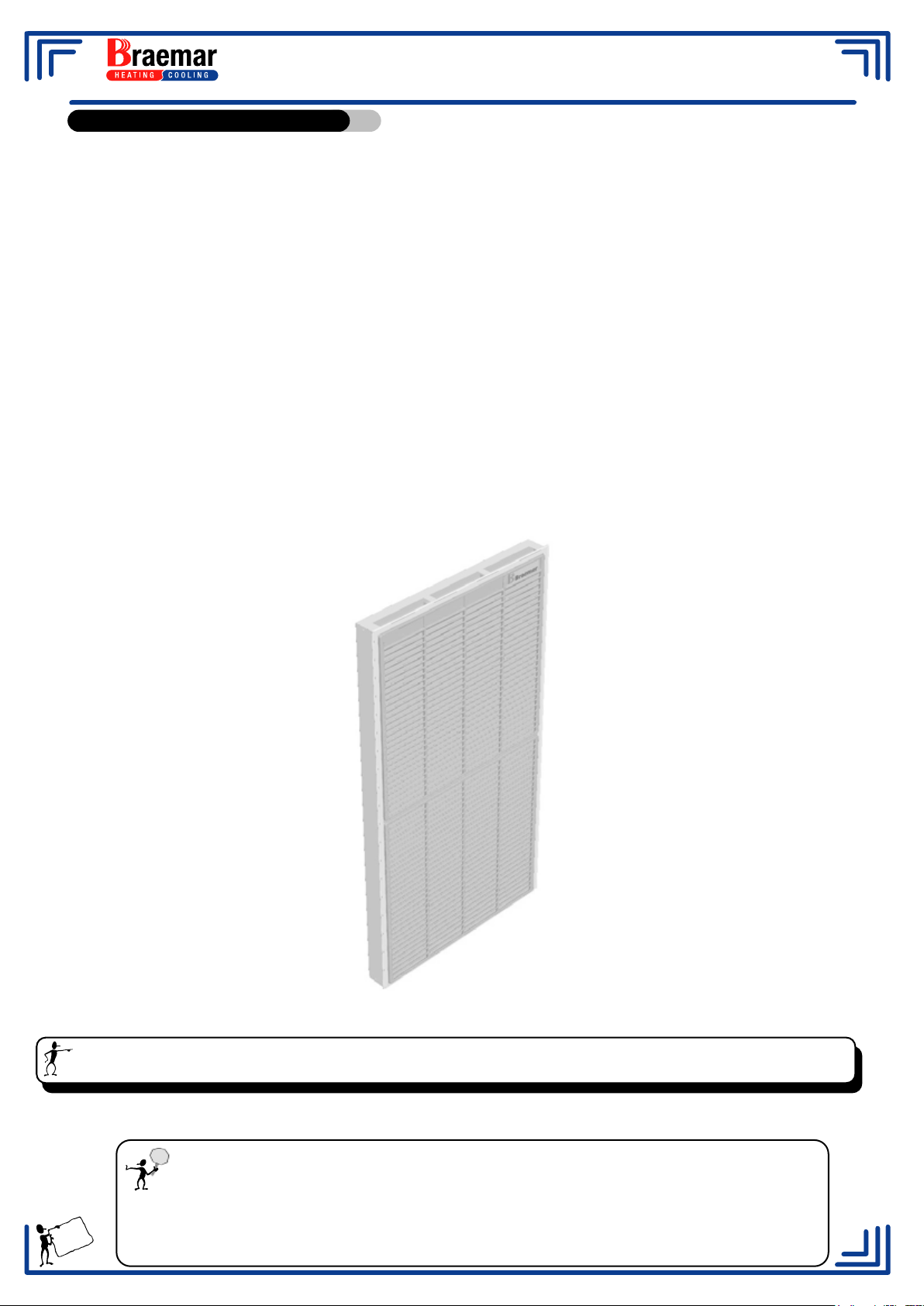
• Remove the pad frames from the air conditioner by turning the black latch at the top of the pads,
tilting the pad outwards and lifting.
• Chillcel
®
Pad - On a suitable work surface area, remove the rivets from the top of the frame, lift
off the top frame, the water tray and pad will lift out.
• Woodwool
Pad - On a suitable work surface area, remove the rivets(s) securing splash guard to
top of pad frame, open the wire frame and remove the pad.
• Using a spray nozzle on a garden hose with a moderate pressure, wash any dirt and salt
deposits from the louvre grille and frames.
• Place the new pad into the frame and secure as before. When replacing pads with wood wool,
ensure that the wood wool is distributed evenly throughout the frame and any protruding strands
are pushed back in. Particular attention should be paid to the corners and edges so that air
cannot bypass the pad.
• Spray the assembly with water to rinse any dust or loose material from the frames, then install
into air conditioner.
Warning! Do not use high water pressure when cleaning Chillcel® pads- Damage will occur.
• Switch the COOL control “ ON “, and check that the trough in the upper part of the pad is filling,
and allowing the water to drain through the holes in the trough.
Important!
New filter pads can take some time to become conditioned and uniformly
saturated when water is first applied. A characteristic odour of wet timber may
19
be experienced during this period.
Page 22
RPA INDUSTRIAL AIR CONDITIONERS
Trouble Shooting.
Inadequate Cooling
PROBABLE CAUSE SUGGESTED REMEDY
Insufficient air discharge
openings.
Inadequate exhaust for area being
cooled, causing high humidity and
discomfort.
Undersized air conditioner.
Ducts blocked or collapsed
Clogged or dirty filter pads.
Dry pads or lack of water while the
air conditioner is operating.
Make sure adequate openings are
provided to exhaust the incoming
cool air.
Open windows, doors etc.
Replace with larger Model.
Repair Ducts
Clean or replace pads.
Check water distribution system
for obstructions. Check pump is
operating.
Excessive Ambient Humidity.
(see also top of page)
Fan running backwards.
Fan running too slowly.
Belt slipping.
Circuit breaker tripped or fuse
blown.
Overload tripped.
During summer when the
humidity is high, the unit will not
work as effectively.Turn the pump
off.
Reconnect the incoming mains for
correct rotation. (3 phase only)
Check motor amps. If below rating
plate specification, adjust motor
pulley to increase fan speed
Tighten belt.
Replace if worn.
Reset or replace.
Reset & check motor amps and
adjust if necessary.
Fan Fails To Start
Power not turned ON
Loose electrical connections.
Faulty control switch.
Motor burned out.
Turn power ON
Check all connections.
Replace.
Replace.
20
Page 23
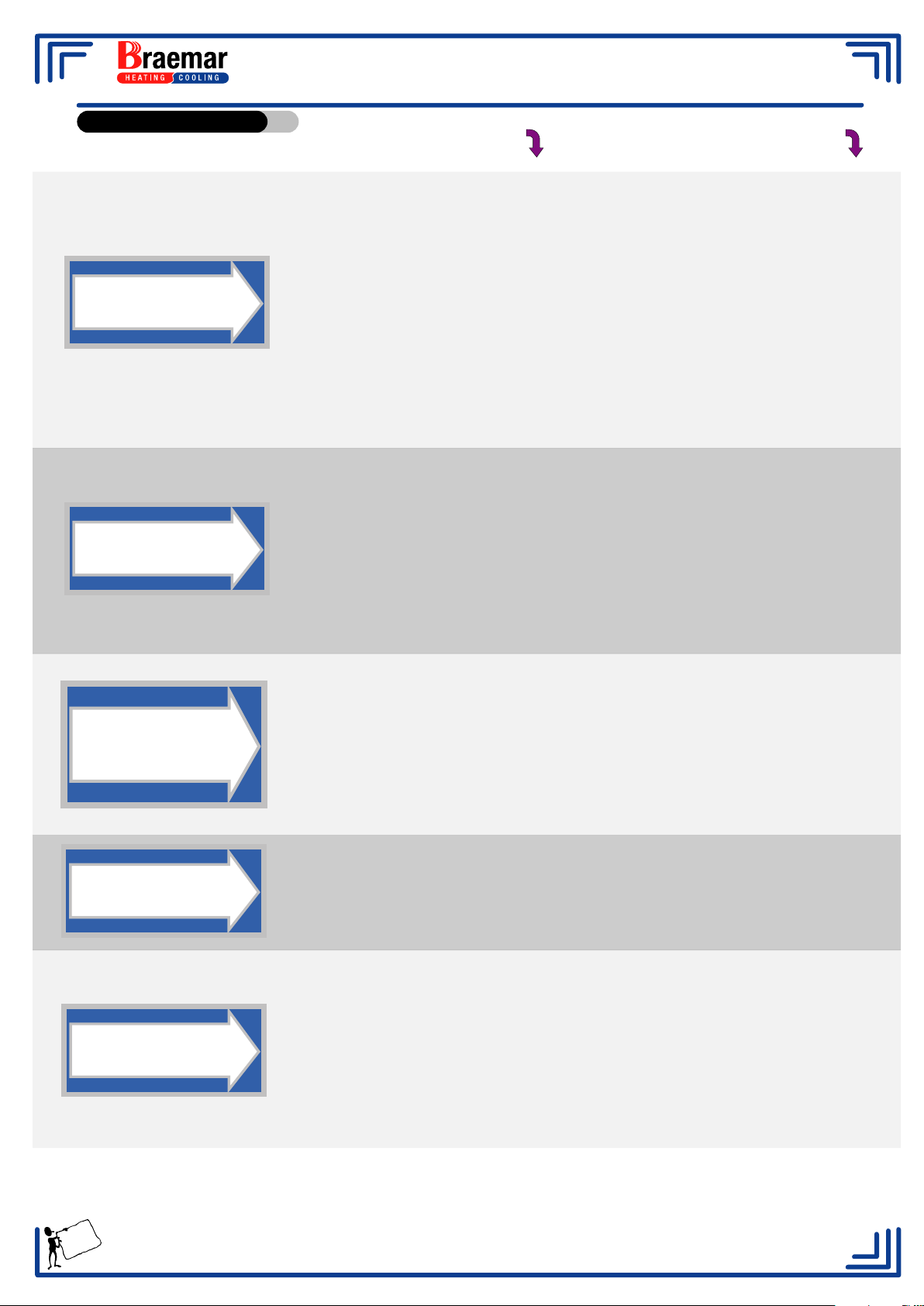
RPA INDUSTRIAL AIR CONDITIONERS
Trouble Shooting.
Motor Overheats
& Trips Overload.
Belt Slipping
Wearing Excessively
PROBABLE CAUSE SUGGESTED REMEDY
Low supply voltage.
Incorrect settings on current
overloads.
Wrong motor size.
Fan speed too high.
Belt loose.
Pulleys out of line.
Worn belts.
Consult with local Electrical
Authority.
Reset overloads to correct setting.
Fit correct size motor.
Adjust motor pulley until the motor
current is equal or below that
specified on motor rating plate
Tighten belt.
Align pulleys.
Replace belts.
Pump runs but does
not circulate water
or pads lack water
Continuous overflow
of water
Pump Fails
To Operate
Worn pulleys.
Insufficient water in tank causing
pump to cavitate.
Pump strainer clogged or dirty.
Blocked water supply tubing.
Incorrect float valve setting.
Inlet valve not sealing
Pump motor failure.
Incorrect wiring of pump.
Loose electrical connections.
Replace pulleys.
Adjust float level to increase water
depth.
Clean strainer.
Clean out water trough.
Adjust float valve
Replace valve
Replace complete pump.
Correct pump wiring.
Tighten connections.
21
Pump control switch faulty.
Replace pump control switch.
Page 24
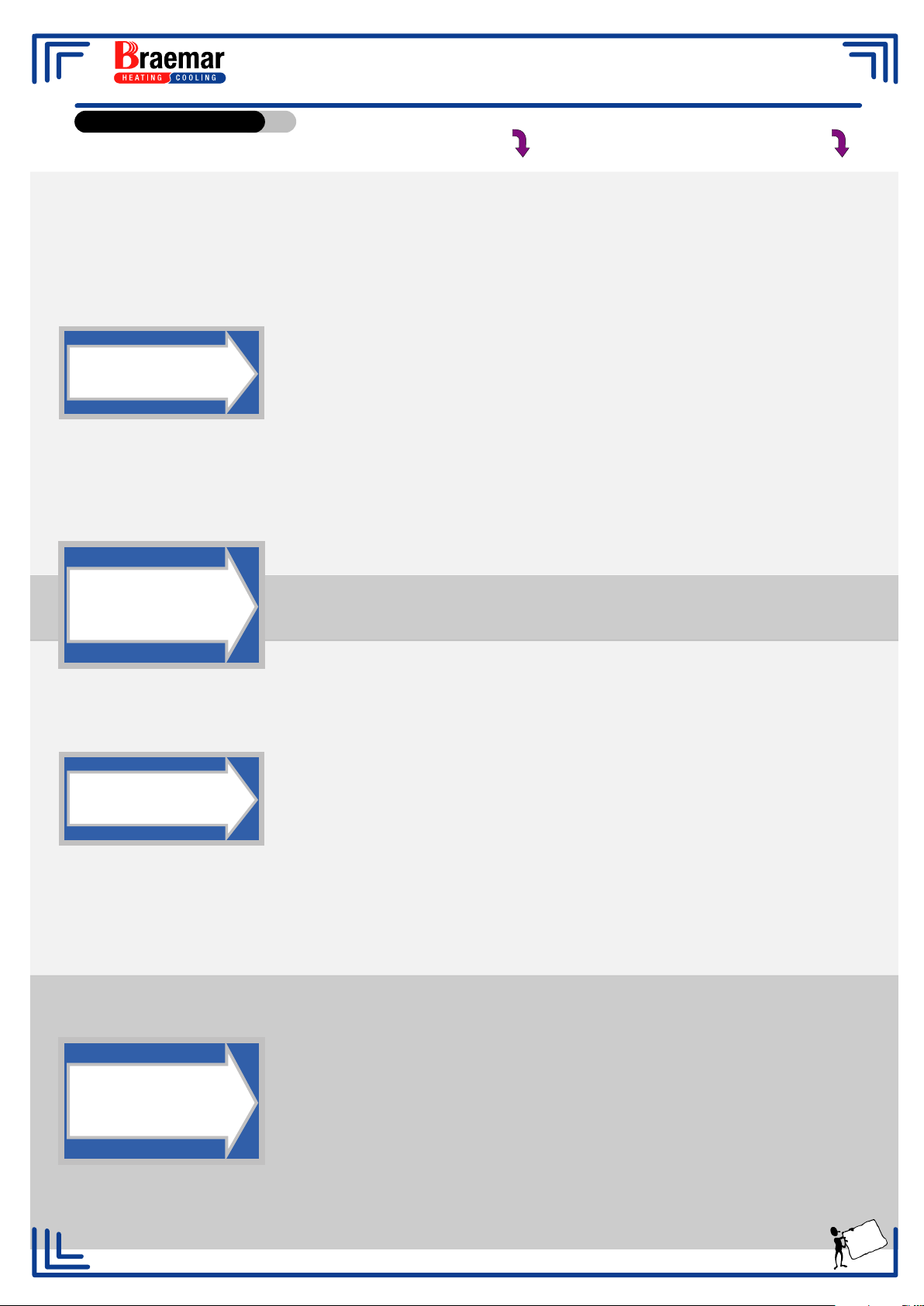
RPA INDUSTRIAL AIR CONDITIONERS
Trouble Shooting.
Noisy Air
Conditioner.
PROBABLE CAUSE SUGGESTED REMEDY
Fan rubbing on housing.
Fan out of balance due to dirt,
bent blade etc.
Air conditioner delivering more air
than required.
Belt "squelching".
Belt "squealing".
Inadequate sized ducts or grilles.
Loose water distribution
connections.
Reposition fan.
Clean fan, adjust blades if
possible: Replace fan.
Adjust any baffles or balance air to
reduce airflow.
Adjust alignment of motor and
pulleys.
Tighten belt by adjusting motor
platform: Replace belt.
Increase grille size.
Tighten all connections.
Formation of white
deposits in tank
and on pads.
Unpleasant
odour.
High mineral content in water
supply.
Air conditioner located near the
source of unpleasant odour.
New Pads fitted
Algae in tank.
Pad remains wet after shutdown.
Break in water distribution system.
Filter pads not properly installed
into pad frames, or sagging.
Increase the bleed rate.
Relocate the air conditioner or
remove the odour source.
Will go after short time.
Drain tank and clean thoroughly,
fill with clean water and install new
pads.
Allow fan to run for further 10
minutes after pump has been shut
off.
Replace any cracked or broken
tubing.
Ensure filter pads are correctly
installed.
Water being thrown
into area being
cooled.
Old filter pads have developed
"thin" spots.
Filter pad fibre sticking through
netting causing water to be
sucked off pad.
Too much water to pads.
Replace with new filter pads.
Remove any fibres protruding
through netting.
Check restrictor tap setting and
adjust if required.
Blocked Pads
22
Page 25
RPA INDUSTRIAL AIR CONDITIONERS
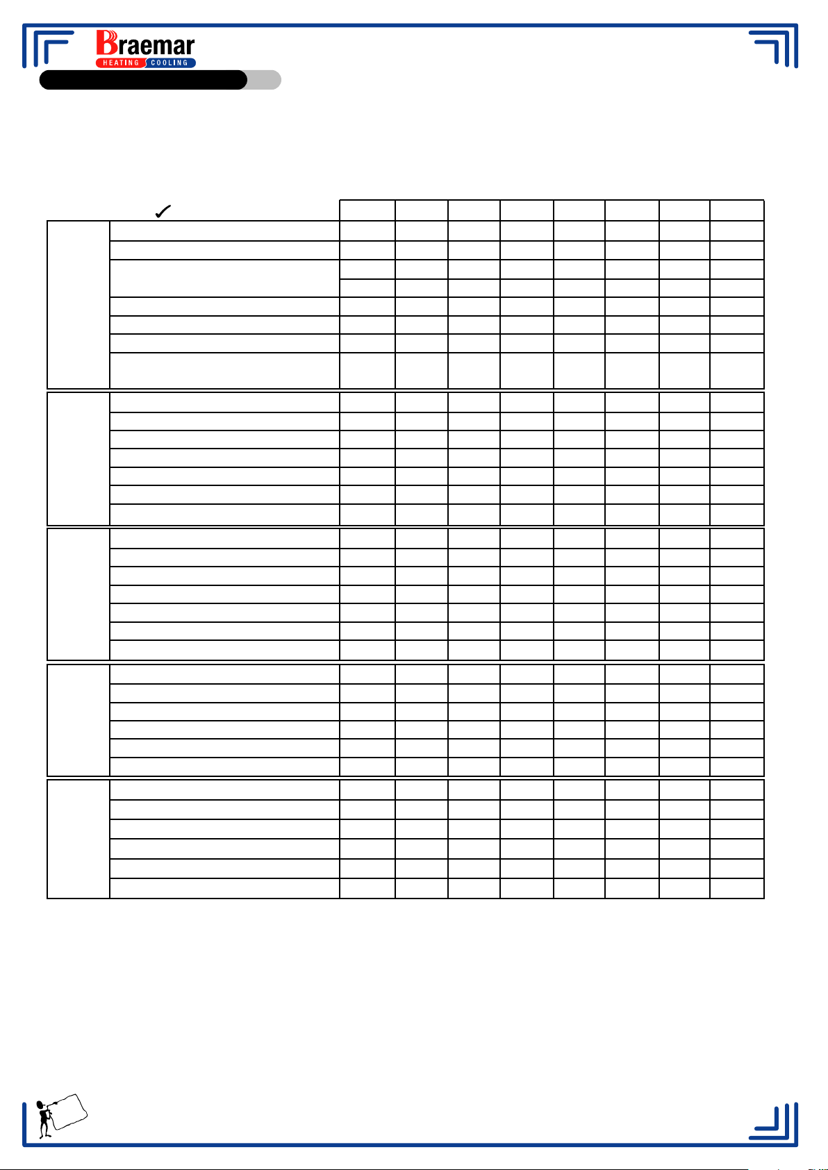
Maintenance Schedule
It is a condition of your warranty cover that the items in the Schedule below are checked (and action taken as required)
four (4) times a year from the date of installation by a qualified, licenced technician, and that the Schedule is properly
filled out (ie names, signature, date, and action taken). Even after the warranty period expires, please continue to have
the product maintained four (4) times a year as per the items in the Schedule. This will help to prolong the life of the
product and keep it running efficiently.
C = clean R = replaced
A = adjust = check
Electrical wiring
Fan Motor / alignment
Check and record overloads settings
Electrical
Water distribution
General
Cabinet and
components
General
PCB’s, contactors and boxes
Drain valve (if applicable)
Water solenoid (if applicable)
Pump1, Pump2, Pump3, Pump4
Pad, pad pins and retaining wire
Water distribution hoses
Water distributors
Water distribution tap settings
system
Water float valve / level
Water probes (where applicable)
Bleed rate (where applicable) record setting
Belt tension / condition
Bearings (grease where required)
Start up and run sequence
Control operation
operation
Motor Amps high speed
Motor Amps low speed
Bleed hoses correctly installed / operating
Cabinet
Pad frames
Tank
Fan, fan blades and alignment
Shaft and alignment
Pulleys and alignment
Electrical connections
Water connections
Duct condition
Roof penetrations
installation
General installation
Access
1st service 2nd service 3rd service 4th service 5th service 6th service
High
Low
High
Low
High
Low
High
Low
High
Low
High
Low
1234 1234 1234 1234 1234 1234
lt/pmlt/pmlt/pmlt/pmlt/pmlt/pm
7th service 8th service
High
Low
High
Low
1234 1234
lt/pmlt/pm
To owner/user: please note that as explained in your Warranty Card, installation is not covered by the warranty
(for example, ductwork, roof penetrations, and electrical and water connections to the Braemar Evaporative Air
Conditioner). However, we still require that you have these things checked, because they can affect the performance
(and/or safety) of the product. This is why we have included them in the Maintenance Schedule.
Service 1 Technician____________________ Company____________________ Date____________
Service 2 Technician____________________ Company____________________ Date____________
Service 3 Technician____________________ Company____________________ Date____________
Service 4 Technician____________________ Company____________________ Date____________
Service 5 Technician____________________ Company____________________ Date____________
Service 6 Technician____________________ Company____________________ Date____________
23
Service 7 Technician____________________ Company____________________ Date____________
Service 8 Technician____________________ Company____________________ Date____________
Page 26

SERVICE: 1300 650 644
For all your Braemar warranty and service needs.
Or
Contact your local Braemar direct dealer.
TECHNICAL SUPPORT CENTRE: 1300 650 399
For technical support regarding
the installation of this product
SALES: 1300 650 141
For all your sales enquiries
Seeley International Pty Ltd has a policy of continuous product development and therefore
reserves the right to make changes to these specifications without notice. Whilst every
care has been taken to assure accuracy of the data compiled in the document,
Seeley International Pty Ltd does not assume any liability for errors and/or omissions.
Braemar is a registered trademark of Braemar Industries Pty Ltd.
Seeley International Pty Ltd ACN 23 054 687 035
Albury Manufacturing
77 North Street Albury, NSW 2640
www.seeley.com.au
Manufacturers and Designers of Technically Advanced Quality Heating and Cooling Products
ECN1550 Doc. No. 601540 /P
 Loading...