

Page 1

OWNER’S MANUAL
HIGH WALL SPLIT INVERTER
(English) (KSHVD1S SERIES)
Page 2
IMPORTANT
As with any product that has moving parts or is subject to wear and tear, it is
VERY IMPORTANT
serviced. Accordingly, it is a condition of warranty cover for your air conditioner
that you comply with all of the maintenance and service requirements set out
in this Manual. Compliance with these requirements will prolong the life of your
air conditioner. Further, it is also a condition of warranty cover that the
Maintenance Schedule in the Manual is filled out (by signing and dating it in
the places indicated) when the item is completed.
OUT THE REQUIRED MAINTENANCE AND SERVICING, AND ANY
FAILURE TO FILL OUT THE MAINTENANCE SCHEDULE, WILL VOID
YOUR WARRANTY.
(For complete warranty terms, refer to the separate Warranty Booklet sold with
the product. Alternatively, visit to download the terms.
Warranty terms are subject to property access and industry safety standards.)
that you maintain your air conditioner and have it regularly
ANY FAILURE TO CARRY
www.braemar.net.au
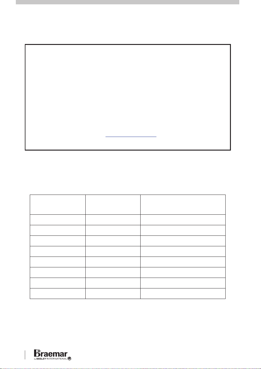
OUTDOOR
MODELS
INDOOR
MODEL
CAPACITY
COOL / HEAT
KSHV25D1SKCHV25D1S 2.5 kW / 3.2 kW
KSHV35D1SKCHV35D1S 3.5 kW / 3.8 kW
KSHV46D1SKCHV46D1S 4.6 kW / 4.7 kW
KCHV52D1S
KCHV60D1S
KCHV70D1S
KCHV80D1S
KCHV90D1S
i
KSHVD1S Series High Wall Inverter Unit
KSHV52D1S
KSHV60D1S
KSHV70D1S
KSHV80D1S
KSHV90D1S
5.2 kW / 5.8 kW
6.1 kW / 7.3 kW
7.0 kW / 8.0 kW
8.0 kW / 9.0 kW
9.4 kW / 10.3 kW
Page 3

CONTENTS
MAIN COMPONENTS.........................................................................................2
INTRODUCTION & SAFETY ...........................................................................3-4
OPERATION
REMOTE CONTROLLER..............................................................................5
CONTROLLER LAYOUT...............................................................................6
ON/OFF .........................................................................................................6
MODE ............................................................................................................6
FAN SPEED...................................................................................................7
CLOCK ..........................................................................................................7
TEMP .............................................................................................................7
▲ ▼/
BUTTONS ...........................................................................................7
X-FAN ............................................................................................................7
TURBO ..........................................................................................................7
LIGHT ............................................................................................................7
QUIET ............................................................................................................8
TIMER SETTINGS.........................................................................................8
SWING UP / DOWN ......................................................................................8
SWING LEFT / RIGHT...................................................................................8
I FEEL............................................................................................................9
SLEEP ......................................................................................................9-10
LOCK FUNCTION .......................................................................................10
FAHRENHEIT / CENTIGRADE ...................................................................10
ENERGY SAVING .......................................................................................10
8°C HEATING FUNCTION ..........................................................................10
WiFi FUNCTION..........................................................................................10
EMERGENCY OPERATION ........................................................................11
WiFi INSTALLATION...................................................................................11
ERROR DISPLAY........................................................................................12
MAINTENANCE & SERVICE............................................................................13
MAINTENANCE SCHEDULE ...........................................................................14
OPERATION TIPS.............................................................................................15
TROUBLESHOOTING ......................................................................................16
WARRANTY & SERVICE..................................................................................17
SEELEY INTERNATIONAL – OWNER’S MANUAL 1
Page 4
MAIN COMPONENTS INTRODUCTION & SAFETY
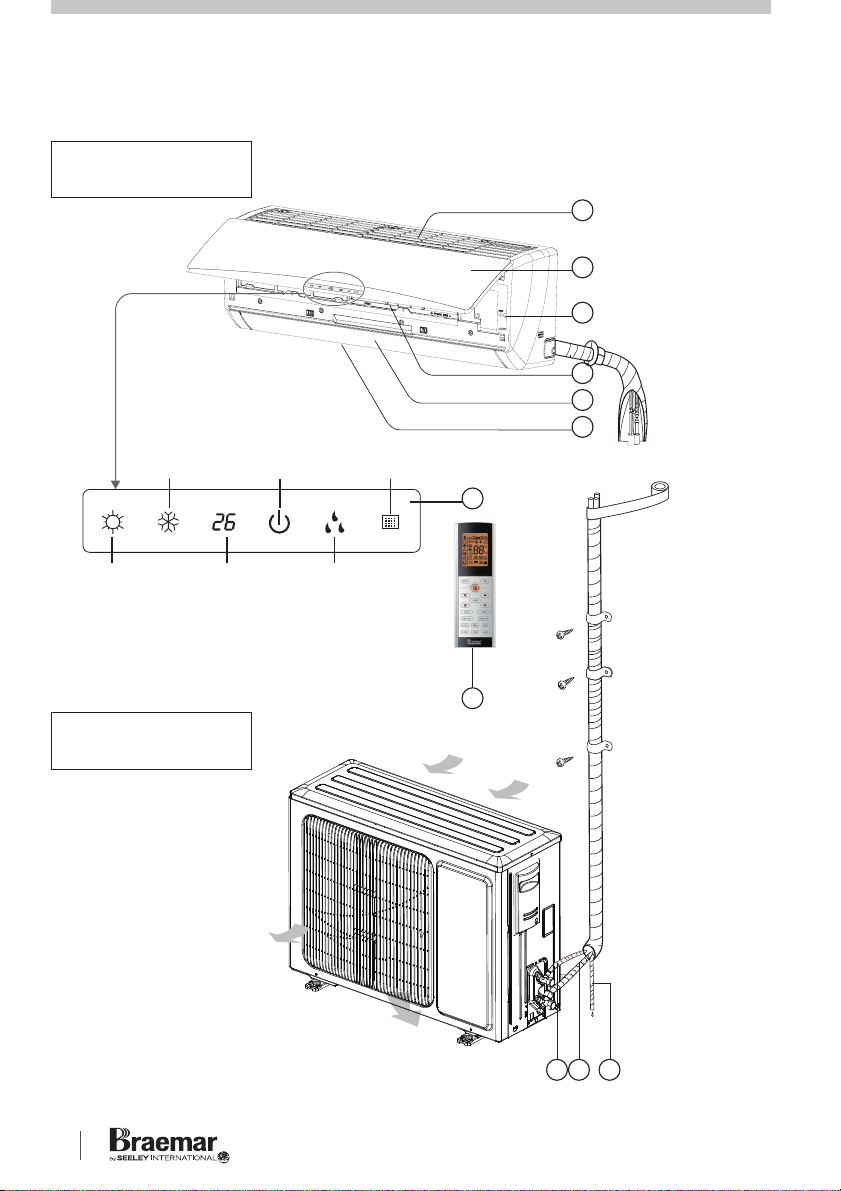
INDOOR UNIT
1
2
3
4
5
6
cooling
indicator
power
indicator
receiver
window
7
heating
indicator
NOTE: Display panel style or position
may differ from the above graphics.
temp.
indicator
OUTDOOR UNIT
KSHVD1S Series High Wall Inverter Unit
drying
indicator
Air outlet
8
Air inlet
1. Air inlet
2. Front panel
3. Aux. button
4. Filter
5. Horizontal
Louvre
6. Air outlet
7. Display panel
8. Remote control
9. Condensate tube
10. Gas Pipe
11. Liquid Pipe
91011
Page 5

Congratulations on purchasing a new
Braemar Air Conditioner!
Please keep this Manual and the
Warranty Booklet in a safe place,
along with the original purchase
documents, plus all relevant
certificates of compliance relating to
the installation work performed. Please
register the Warranty straight away, by
following the steps set out in the
Warranty Booklet.
The installer must read the Installation
Manual before installing the Braemar
High Wall Inverter Air Conditioning
Unit. The home owner/user should
read the Owner's Manual before
operating the Unit.
To ensure the warranty on the Unit is
continued and valid, the Unit must be
checked and serviced by the home
owner/user as per the requirements in
the Maintenance & Service section
and the Maintenance Schedule. This
will also prolong the life of your air
conditioner.
IMPORTANT!
THE AUSTRALIAN GREENHOUSE
OFFICE HAS ISSUED VARIOUS
REGULATIONS ON THE USE AND
DISPOSAL OF REFRIGERANTS IN
THE UNIT. FAILURE TO FOLLOW
THESE REGULATIONS MAY HARM
THE ENVIRONMENT AND COULD
LEAD TO THE IMPOSITION OF
SUBSTANTIAL FINES.
WHERE SPECIFIED, ONLY
QUALIFIED AND LICENSED
TECHNICIANS SHOULD PERFORM
WORK ON THIS UNIT, FAILING
WHICH THE WARRANTY ON THE
UNIT WILL BE VOID.
WARNING! This appliance is not
intended for use by persons (including
children) with reduced physical,
sensory or mental capabilities, or lack
of experience and knowledge, unless
they have been given supervision or
instruction concerning use of the
appliance by a person responsible for
their safety.
The home owner/user should regularly
check the Air Inlet side of the Outdoor
unit (see the diagram on page 2) to
ensure grass, leaf and other matter are
not drawn into or onto the Inlet side of
the Outdoor unit. Restriction to the air
flow across the coil will reduce the
system's capacity, and result in high
operation pressures and excessive
operating costs.
Children should be supervised to
ensure that they do not play with the
appliance.
If the supply cord is damaged, it must
be replaced by the manufacturer, its
service agent or similarly qualified
persons in order to avoid a hazard.
SEELEY INTERNATIONAL – OWNER’S MANUAL 32
Page 6
SAFETY cont.
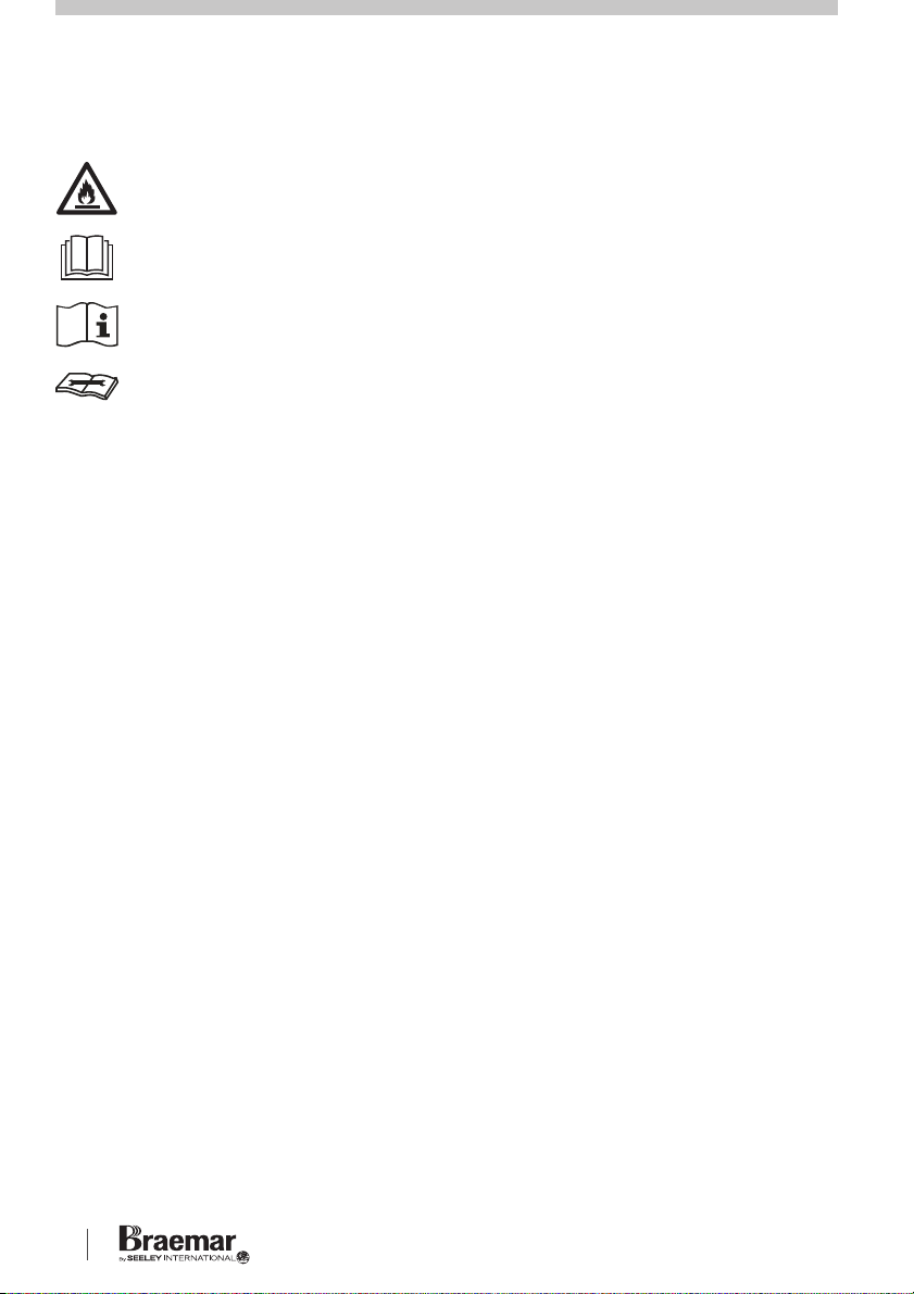
Appliance filled with flammable gas R32.
Before using the appliance, read the owner’s manual first.
Before installing the appliance, read the installation manual first.
Before repairing the appliance, read the service manual first.
REFRIGERANT
For product efficiency, a special
refrigerant R32 is used in the air
conditioner. Cmopared to common
refrigerants, R32 is a non-polluting
refrigerant which will not harm the
ozonosphere and has a much lower
greenhouse potential. This refrigerant
is flammable and inodorous. The
flammability is very low and can only
be ignited by an open flame. However
under certain conditions it can
explode.
WARNING
Do not use means to accelerate the
defrosting process or to clean, other
than those recommended by the
manufacturer.
The appliance shall be stored in a
room without continuously operating
ignition sources (for example: open
flames, an operating gas appliance or
an operating electric heater). It
shall be
stored in a well-ventilated area where
the room size corresponds to the room
area as specified for operation (refer
Installation manual).
WARNING
Do not pierce or burn.
Be aware that refrigerants may not
contain an odour.
Before any servicing on the air
conditioner, the service manual should
be read and understood by service
personnel. Servicing shall be
performed only as recommended in
the service manual. Any repairs
carried out by unqualified personnel
may be dangerous.
KSHVD1S Series High Wall Inverter Unit
Page 7
OPERATION
Your Braemar
Conditioning Unit
High Wall Inverter Air
has been designed
and built with reliable, quality
components. To ensure many years of
trouble free, dependable service
please read the following pages very
carefully, and please ensure that you
follow all of the instructions.
REMOTE CONTROLLER
Please follow the below cautionary
notes when using the remote
controller:-
1. Ensure there are no obstructions
between the High Wall receiver and
remote controller.
2. Don’t let the remote control drop
onto hard surfaces or be subjected to
sudden shocks in any way.
the remote control to get wet.
Don’t allow
The
warranty does not cover misuse or
accidental damage.
3. Don’t place the remote control in
direct sunlight, or near extremes of
temperature. This will affect the
control’s temperature reading.
NOTE:
This is a generic remote
control, used for multiple types of air
conditioner. Not all functions shown
on the remote control may be
operational for this unit.
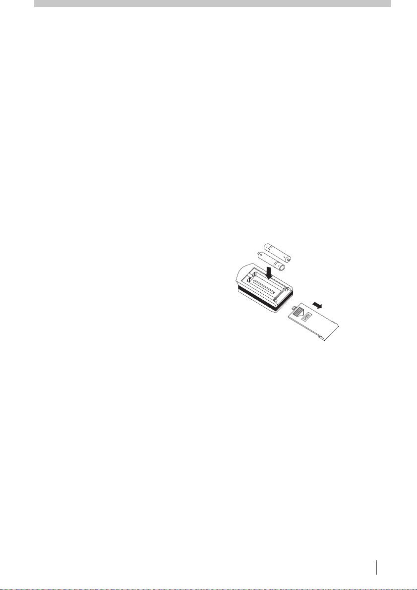
CHANGING BATTERIES
Push down on the battery panel to
open the battery compartment area.
Insert 2 x AAA 1.5V batteries, ensuring
the polarity aligns with the markings in
the battery compartment (refer below).
2
If the remote controller does not
activate, remove the batteries and reinsert after waiting 30 seconds.
4. Don’t place near strong
electromagnetic waves.
5. Don’t mix old and new batteries! If
the remote control will not be used for
a long time, remove the batteries to
avoid corrosion.
6
. Before operating the air conditioner,
please read this manual carefully and
keep it in a safe place for future
reference.
SEELEY INTERNATIONAL – OWNER’S MANUAL 54
Page 8
OPERATION cont. OPERATION cont.
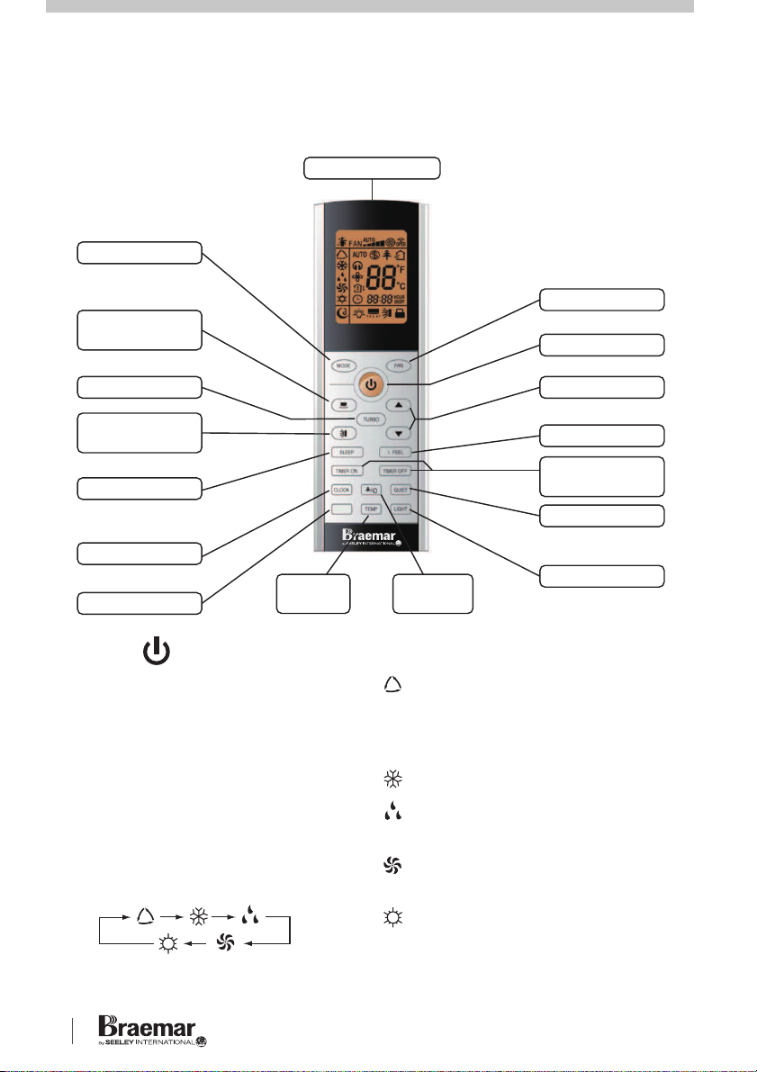
CONTROLLER LAYOUT
Signal transmitter
MODE button
SWING L / R
button
TURBO button
SWING UP /
DOWN button
SLEEP button
CLOCK button
WiFi button
WiFi
TEMP
button
ON / OFF
Press to turn the power on or off.
SLEEP function will be cancelled when
power is turned off.
WiFi
FAN button
ON/OFF button
▲ ▼/ buttons
I FEEL button
TIMER ON /
OFF buttons
QUIET button
HEALTHY
button
LIGHT button
MODE cont.
AUTO Mode - cycles between
COOL and HEAT modes
depending on ambient
temperature.
MODE
Press to toggle between AUTO,
COOL, DRY, FAN and HEAT modes.
The remote controller & indoor will
display the below icons:-
KSHVD1S Series High Wall Inverter Unit
.
COOL Mode - refrigerated cooling
DRY mode - for extracting
moisture from the air.
FAN mode - Fan only operation
(no cooling).
HEAT mode - reverse cycle
heating. NOTE: unit will delay 1-5
minutes to prevent cold air being
circulated.
Page 9
FAN SPEED
▲ ▼/ BUTTONS
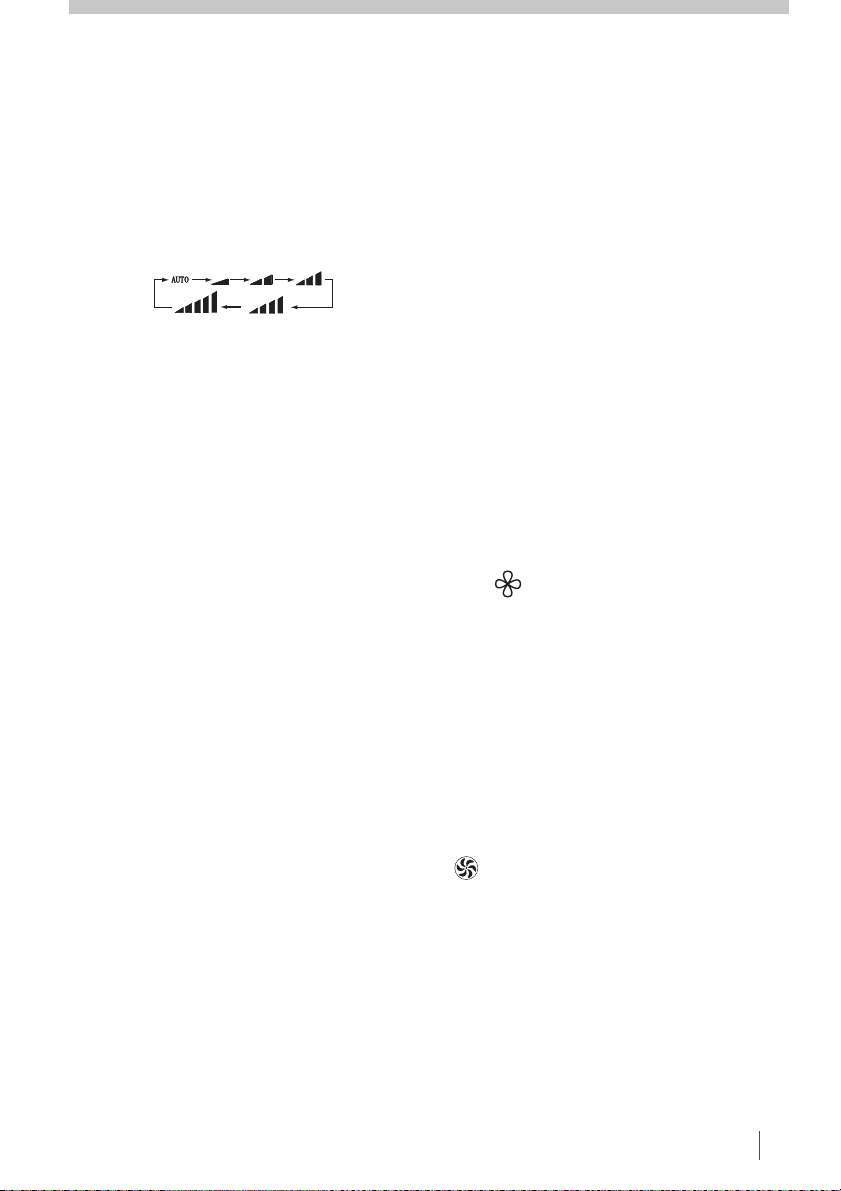
Press the FAN button to toggle
between AUTO, Low, Medium-Low,
Medium, Medium-High and High
speed.
AUTO fan speed is default on power
up. In DRY mode, only Low FAN
speed is selected.
CLOCK
Press the CLOCK button to set the
clock time. will flash on the display,
¹
and the clock can be adjusted by
pressing the
▲ ▼or buttons. Once
the correct time is set, press the
CLOCK button again to confirm the
clock setting. will be displayed
¹
continuously, this indicates the clock
time is set. ‘12:00' is the default
setting after power up. Set the correct
time to enable the TIMER function to
work correctly.
Use to adjust the SET temperature
within the range 16-30°C (61-86°F).
Hold the button down for quick
adjustment.
Note: TEMP adjustment is unavailable
in AUTO mode.
X-FAN
The X-FAN function can be used
COOL or DRY modes, so as
in
to
continue operation of the indoor fan for
an additional 10 minutes after the
power is turned off (so as to remove
excess moisture from the indoor coil).
Press the Fan speed button for 2 s.
The icon will be displayed.
Repeat this to turn X-FAN off.
Default setting is X-FAN ‘OFF’, and is
not available in AUTO, FAN or HEAT
modes.
TURBO
TEMP
Press the TEMP button to toggle
between the following on the indoor
display:-
SET temperature (room target
·
temperature)
Indoor ambient temperature
·
Outdoor ambient temperature (when
·
equipped)
Note: remote controller will always
display the SET temperature.
When the unit is first turned on in
COOL or HEAT modes, press TURBO
to quickly reach the SET temperature.
icon will be shown on the remote
controller display. TURBO mode is
cancelled if MODE or FAN speed is
changed.
LIGHT
Press the LIGHT button to toggle
between LIGHT ON and LIGHT OFF
status. Default is LIGHT ‘ON’.
SEELEY INTERNATIONAL – OWNER’S MANUAL 76
Page 10
OPERATION cont.
QUIET
QUIET function can be employed to
use lower fan speeds to attain the SET
temperature when in AUTO, COOL
and HEAT modes. The icon will
be displayed.
Note: QUIET function cannot be set in
FAN or DRY modes. Fan speed
cannot be changed when QUIET mode
is set. Default is QUIET mode ‘OFF’.
TIMER SETTINGS
The unit can be programmed to turn
on, turn off or a combination of both
when in standby or power ON modes.
Use the below settings.
TIMER ON
Press the button to enter
the setup. The icon will disappear
TIMER ON
¹
and “ON” will blink on the remote
controller display. Use the
▲ ▼or
buttons to adjust the clock time for the
unit to start. Holding these buttons will
produce rapid adjustment.
TIMER OFF cont.
controller display. Use the ▲ ▼or
buttons to adjust the clock time for the
unit to stop. Holding these buttons
down will produce rapid adjustment.
When complete, press the TIMER OFF
button again to set.
Pressing the TIMER OFF button again
will cancel the TIMER OFF function.
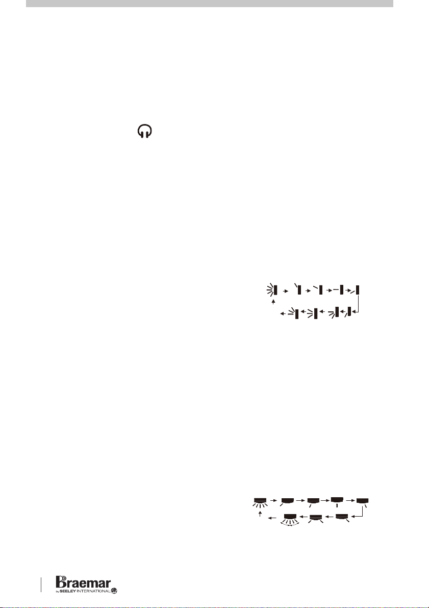
SWING UP / DOWN
Press to adjust the UP/DOWN louvre,
each press will toggle between the
below settings:-
OFF
Where a single line indicates a fixed
position, multiple lines indicate
swinging up/down in the positions
shown.
If the louvre is set to OFF when
swinging, it will remain fixed in the last
position.
When complete, press the TIMER ON
button again to set.
Pressing the TIMER ON button again
will CANCEL the TIMER ON function.
TIMER OFF
Press the TIMER OFF button to enter
the setup. The icon will disappear
¹
and “OFF” will blink on the remote
KSHVD1S Series High Wall Inverter Unit
SWING LEFT / RIGHT
Press to adjust the LEFT/RIGHT
louvre, each press will toggle between
the below settings:-
OFF
Page 11

OPERATION cont.
I FEEL
Press the I FEEL button to activate this
feature. The remote controller will act
as the temperature thermostat,
sending a temperature reading to the
unit every 10 minutes. By this method,
the unit will react to where the remote
controller is positioned. The icon
will be shown on the remote controller
display.
Press the I FEEL button again to
cancel
this feature.
SLEEP
Press SLEEP button to toggle between
the SLEEP modes and cancel, as
described below. Default setting is
SLEEP mode ‘OFF’:-
SLEEP 1:
In COOL and DRY modes,
after running for one hour, the main
unit SET temperature will increase by
1°C, then after 2 hours will increase by
2°C, then will continue to run at this
temperature.
SLEEP cont.
has elapsed. It will then be decreased
by 1°C, then will continue to run at this
temperature.
b) If SET between 24-27°C, SET
temperature will increase by 1°C every
hour for 2 hours, then stay constant
until 7 hours has elapsed. It will then
be decreased by 1°C, then will
continue to run at this temperature.
c) If SET between 28-29°C, SET
temperature will increase by 1°C for 1
hour, then stay constant until 7 hours
has elapsed. It will then be decreased
by 1°C, then will continue to run at this
temperature.
d) If SET at 30°C, SET temperature
will stay constant until 7 hours has
elapsed. It will then be decreased by
1°C, then will continue to run at this
temperature.
In HEAT mode:-
a) If SET at 16°C, it will remain at this
temperature.
In HEAT mode, the SET temperature
will decrease by 1°C and then 2°C for
the first 2 hours, and then stay
constant.
SLEEP 2:
In COOL mode, the SET
temperature will vary according to the
below scenarios:-
a) If SET temperature starts between
16-23°C, SET temperature will
increase by 1°C every hour for 3
hours, then stay constant until 7 hours
b) If SET between 17-20°C, SET
temperature will decrease by 1°C for 1
hour, then will continue to run at this
temperature.
c) If SET between 21-27°C, SET
temperature will decrease by 1°C for 2
hours, then will continue to run at this
temperature.
SEELEY INTERNATIONAL – OWNER’S MANUAL 98
Page 12
OPERATION cont. OPERATION cont.
SLEEP cont.
d) If SET between 28-30°C, SET
temperature will decrease by 1°C for 3
hours, then will continue to run at this
temperature.
SLEEP 3:
this is a User programmable
curve, created as follows:-
a) When in SLEEP 3 mode, hold the
TURBO button down until the remote
displays ‘1 hour’ and the SET
temperature will display.
b) Adjust the SET temperature, then
press TURBO button to confirm.
c) The remote display will move to the
next time setting (’2 hours’, ‘3 hours’ or
‘8 hours’), and the SET temperature
can agin be programmed.
d) Repeat until the ‘8 hours’ SET
temperature has been entered. Once
completed, the remote display will
show the original settings.
The SLEEP 3 settings will be stored
and can be reviewed at any time in the
SLEEP 3 mode by pressing the
TURBO button and scrolling through
without adjusting the settings.
Review mode will be quit if no button is
pressed within 10 seconds, or if the
ON/OFF, MODE, TIMER or SLEEP
buttons are pressed.
LOCK
The remote controller can be locked
from inadvertent button operation.
Press both or buttons▲ ▼
simultaneously to lock (or unlock) the
remote controller. The icon will
be displayed, and will flicker when a
button is pressed.
FAHRENHEIT / CENTIGRADE
The temperature display can be
toggled between Centigrade and
Fahrenheit scales by pressing the
MODE and buttons simultaneously.
▼
ENERGY SAVING
When in COOL mode, press the TEMP
and CLOCK buttons simultaneously to
start Energy Saving function. The
remote controller display will show the
‘SE’ icon. Repeat to cancel.
8°C HEATING FUNCTION
When in HEAT mode, press the TEMP
and CLOCK buttons simultaneously to
start 8°C Heating function. The
remote display will show and a
selected temperature of ‘8°C’ (46°F).
Repeat to cancel.
WiFi FUNCTION
Press the WiFi to toggle WiFi function
on or off. The “WiFi” icon will appear
on the remote control display when in
use.
To restore factory default settings on
the WiFi module, press “MODE” and
“WiFi” buttons simultaneously for 1s
when the unit is OFF.
KSHVD1S Series High Wall Inverter Unit
Page 13
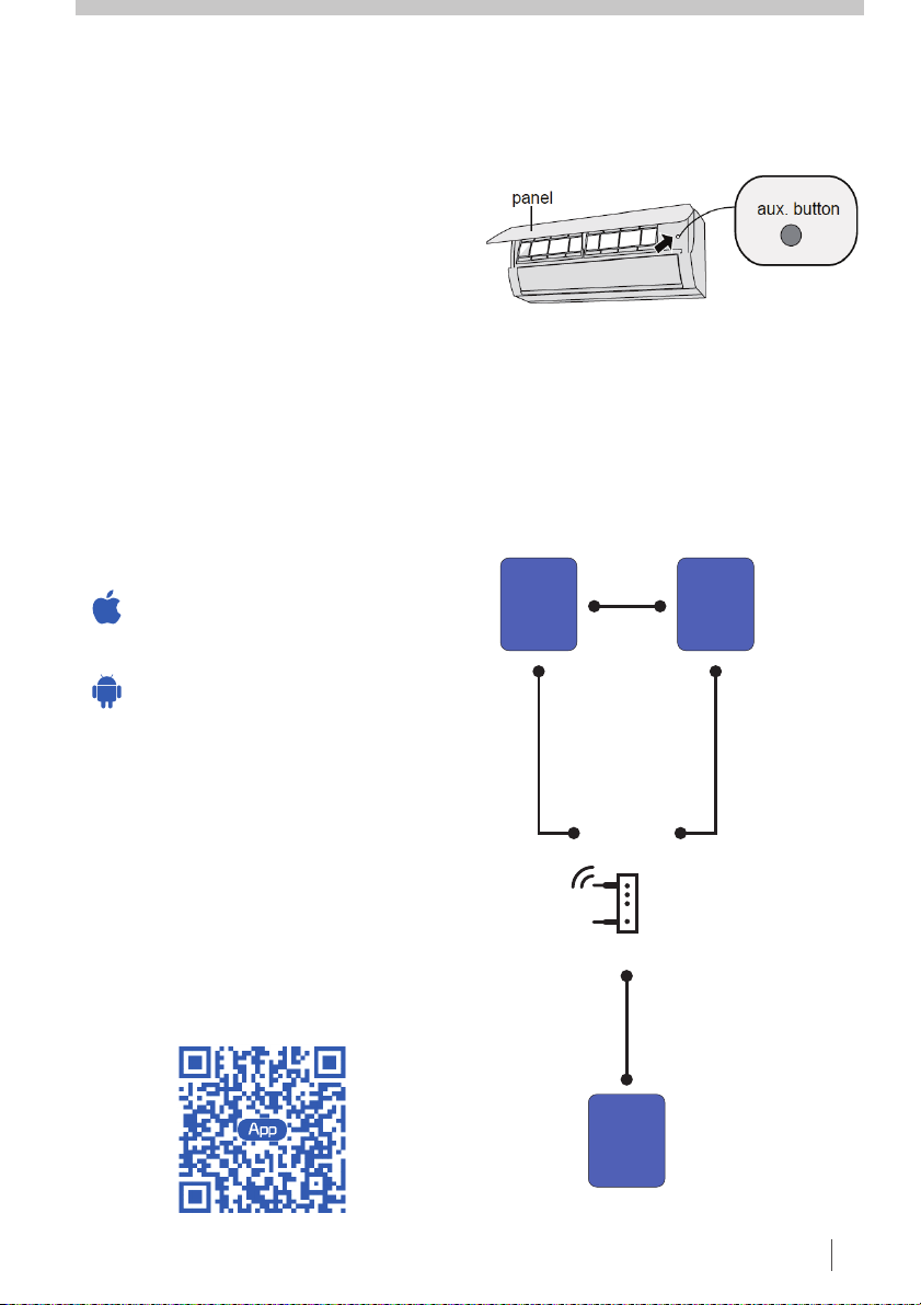
EMERGENCY OPERATION
If the remote controller is lost or
damaged, you can use the ‘auxkiliary’
button to turn on or off the air
conditioner. Open the front panel,
press aux. button to turn on (or off) the
air conditioner. Air conditioner will
operate in AUTO mode.
WiFi INSTALLATION
WARNING: Use an insulated object to
press the aux. button.
OPERATING SYSTEMS
Requirements for User’s smart phone:
iOS system
Support iOS7.0 and
above version
Android system
Support Android 4.0 and
above version
DOWNLOAD AND INSTALLATION
Scan the QR code or search ‘Ewpe
smart” from the application market to
download and install it. When “Ewpe
Smart” app is installed, register the
account and add the device to achieve
long distance control and LAN control
of smart home devices. For more
information, please refer to “Help” in
the App.
CONTROL FLOW CHART
Cloud
Internet
Cellular /
Other WiFi
Home wireless
Home WiFi
APP
Home WiFi
router
App Download Linkage
home
Intelligent
appliances
SEELEY INTERNATIONAL – OWNER’S MANUAL 1110
Page 14
OPERATION cont.
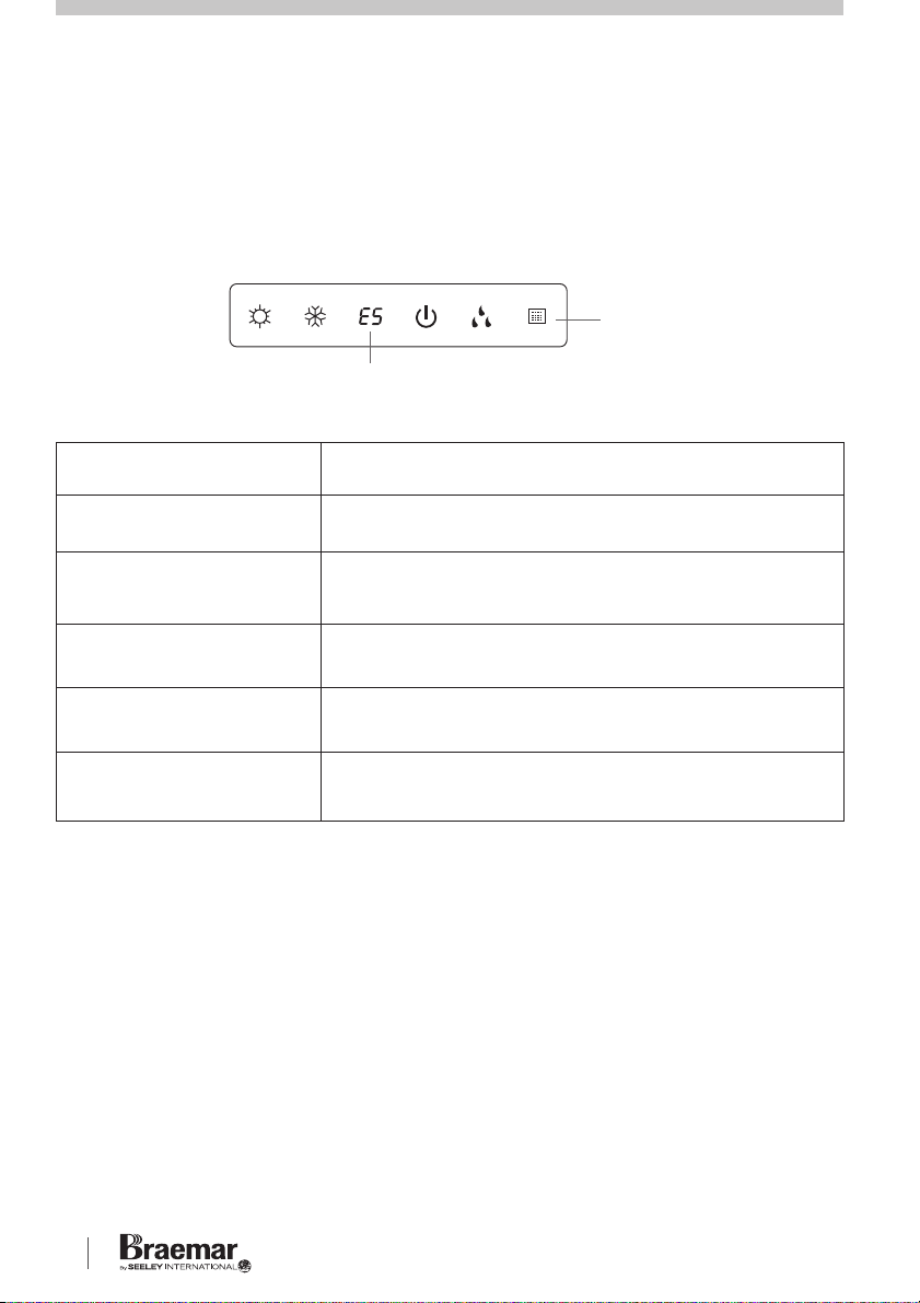
ERROR DISPLAY
Your High Wall air conditioner includes abnormal operation detection hardware
and software. If the unit enters an abnormal state, the temperature indicator on
the fascia display will blink to display a corresponding error code.
Indoor
display
Error code (example only)
Common error codes and their meanings are shown below:
Error Code
E1
E5
E8
H6
d1, d2, d3
Error Description
It can be reset by restarting the unit. If not, please
contact Seeley qualified service agents.
It can be reset by restarting the unit. If not, please
contact Seeley qualified service agents.
It can be reset by restarting the unit. If not, please
contact Seeley qualified service agents.
It can be reset by restarting the unit. If not, please
contact Seeley qualified service agents.
DRED mode 1 (full shut down), mode 2 (50% power) or
Mode 3 (75% power) signal received from Power Grid
Note: if there are other error codes displayed, please contact Seeley qualified
service agents for details.
Please note the error code displayed when contacting Seeley service.
FAULT CONDITIONS
If the below conditions should occur, please turn off the air conditioner and
isolate its power immediately, and then contact the Seeley qualified service
agents for assistance.
Power cord is overheating or damaged.
·
Abnormal sound during operation.
·
Circuit breaker is continually tripping.
·
Burning smell is noticed.
·
Indoor unit is leaking condensate
·
KSHVD1S Series High Wall Inverter Unit
Page 15
MAINTENANCE & SERVICE
SAFETY
Always isolate power for the air
conditioner from electricity mains
before cleaning or maintenance.
AIR FILTER
It is important to check and clean the
air filter as per the Maintenance
Schedule. A dirty air filter will not allow
the correct amount of clean air to pass
through your air conditioner, resulting
in poor performance and increased
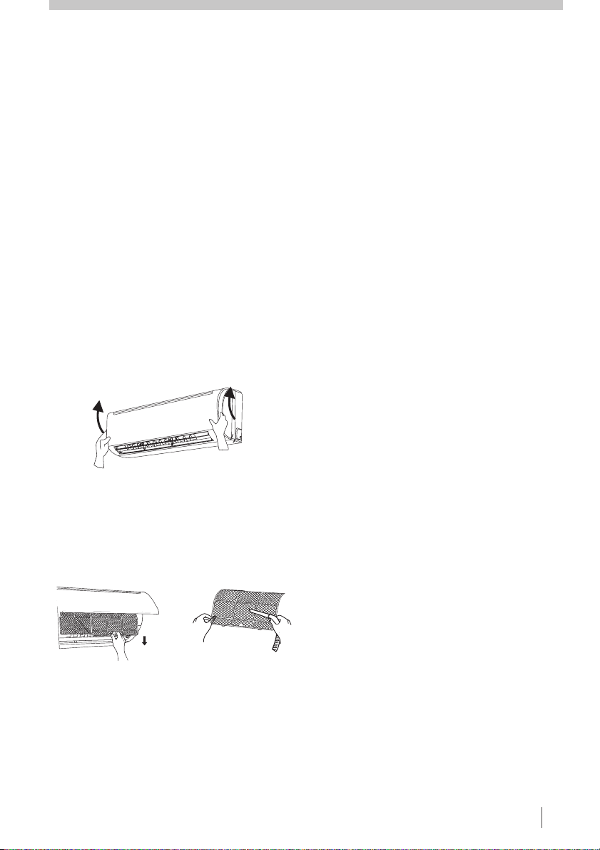
running costs. Please follow the below
steps:-
1. Pull the front panel out and up from
the bottom as shown.
2. Remove the air filter and clean with
a vacuum cleaner. If it is very dirty,
wash with mild soapy water (below
45°C) and wipe off. Dry in the shade.
INDOOR COIL (REFER PAGE 2)
Ensure drain connections are checked
on an annual basis (as set out in the
Maintenance Schedule below). Drains
can become blocked by all types of
insects, and rats have been known to
chew through the drain to get to the
water in the pipe.
OUTDOOR UNIT
(REFER PAGE 2)
The Outdoor unit has either one or two
fans, it draws air through the appliance
to expel the heat generated during the
cooling cycle. We recommend
checking that plants haven't grown into
or around the air intake or outlet, along
with other debris that may build up
over time, namely, leaves and the like.
REFRIGERANT
A lack of refrigerant, due to a leak, will
cause the compressor to overheat and
expire prematurely. You will notice a
decline in cooling effect and an
increase in power consumption.
Therefore, having a qualified, licensed
technician service your air conditioner
will save you money in the long term.
3. Make sure it is completely dry
before refitting it. You should never
operate the air conditioner without the
air filter in place.
PLEASE REFER TO THE NEXT
PAGE FOR THE MAINTENANCE
SCHEDULE
SEELEY INTERNATIONAL – OWNER’S MANUAL 1312
Page 16
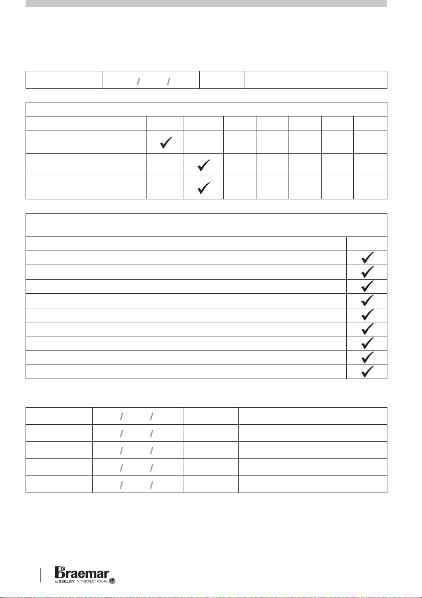
MAINTENANCE SCHEDULE
Installation Date:
Items to be done by the (please sign in the places indicated)Home Owner/User
Air filter cleaning
Air filter replacement
Maintain required clearance
around Outdoor unit
Items to be done by a
(Home owner/user must ensure that the technician signs and dates in the places indicated)
Check, clean or replace filter
Check drain from indoor coil
Check Outdoor unit clearances – maintain garden and debris
Check refrigerant charge
Check refrigeration connections for soundness
Check outdoor fans
Check electrical connections
Check overall installation
Report to the home owner/user all tasks that require attention
/ /
Monthly Annually Year 1 Year 2 Year 3 Year 4 Year 5
Qualified Licensed Technician
Installer:
Annually
Year 1 – Date:
Year 2 – Date:
Year 3 – Date:
Year 4 – Date:
Year 5 – Date:
Please NOTE: the Maintenance Schedule covers Year 1 to Year 5. To preserve your
investment for many years afterwards, we strongly recommend that you continue to
maintain and service the Braemar Cassettel Inverter Air Conditioning Unit as per the items
and frequency set out in the Schedule, and as indicated elsewhere in this Manual.
/ /
/ /
/ /
/ /
/ /
KSHVD1S Series High Wall Inverter Unit
Technician:
Technician:
Technician:
Technician:
Technician:
Page 17

OPERATION TIPS
The following events may occur during normal operation:
1. Protection of the air conditioner.
Compressor protection
• The compressor cannot restart for 3 minutes after it stops.
•
The supply air drops below a pre-determined set point; this prevents
the indoor coil from freezing.
2. A white mist coming out from the Indoor unit.
•
A white mist may generate due to a large temperature difference
between air inlet and air outlet on COOL mode in an indoor
environment that has a high relative humidity.
3. Low noise of the air conditioner.
•
You may hear a low hissing sound when the compressor is running or
has just stopped running.
This sound is the sound of the refrigerant flowing or coming to a stop.
•
You can also hear a low “squeak” sound when the compressor is
running or has just stopped running.
This is caused by heat expansion and cold contraction of the plastic parts
in the Unit when the temperature is changing.
4. Dust is blown out from the Indoor unit.
This is a normal condition when the air conditioner has not been used for a
long time or during first use of the Unit.
5. A peculiar smell comes out from the Indoor unit.
This is caused by the Indoor unit giving off smells permeated from building
material, from furniture or smoke (for example if someone is cooking food).
6. FAN operation during COOL mode.
When indoor air temperature reaches the setting on the remote controller, the
compressor will stop operating and after approximately 60 seconds the indoor
fan will stop blowing air. When the room temperature rises back to the set
point, the indoor fan and the compressor will start again.
SEELEY INTERNATIONAL – OWNER’S MANUAL 1514
Page 18
TROUBLESHOOTING
Problem Probable Cause Remedy
1. The air conditioner
does not run.
1.1 Power failure.
1.2 Fuse blown or circuit
breaker open.
1.3 Thermostat adjustment
too low (in heating mode)
or too high (in cooling
mode).
1.1 Wait for power to resume.
1.2 Replace the fuse or reset
1.3 Check thermostat setting.
the breaker.
Is remote in a cold (COOL
mode) or hot (HEAT
mode) location.
2. Remote controller
is not operating the
air conditioner.
3. There is insufficient
cooling.
4. ‘Clicking’ sound is
heard from the air
conditioner.
5. SET temperature
can’t be adjusted.
6. Cooler is not
operating at full
power, or at all
2.1 Remote controller is out
of range.
2.2 Poor signal reception.
2.3 No display on remote
controller.
3.1 The room was probably
very hot when you
started the system.
3.2 Air filter is dirty / blocked.
4.1 In heating or cooling
operation any plastic
parts may expand or
shrink due to a sudden
temperature change in
this event, a clicking
sound may occur.
5.1 Unit is operating in AUTO
mode.
5.2 The required SET
temperature is outside of
the allowable range.
6.1 DRED (Demand
Response energy saving)
mode has been activated
by the Electricity
Supplier.
2.1 Signal range is 8m.
2.2 Remove obstacles and
electrical interference.
2.3 Check batteries and
replace as needed.
3.1 Wait a while so the Unit
has enough time to cool
the room.
3.2 Clean the filter.
4.1 This is normal.
5.1 Temperature cannot be set
in AUTO mode.
5.2 SET temperature range is
16-30°C
6.1 DRED will stop grid power
demands are reduced
KSHVD1S Series High Wall Inverter Unit
Page 19

WARRANTY & SERVICE
For prompt, efficient service, please follow the above before calling the
appropriate number below.
For Refrigerated Cooling Issues 1300 526 477
When calling the Warranty Service number, please ensure you have your model
and serial number available, along with date of purchase, and if possible a
description of the problem.
NOTE:
Seeley International strives for continuous product improvements, therefore specifications are subject
to change without notice. Unit colour may vary slightly from that depicted in this booklet.
Installation and commissioning of this system to the manufacturer's specification, and compliance
with industry standards, and local, state and national regulatory codes, are the responsibility of the
installer.
Information in this booklet was true and correct at the time of publishing. E & OE.
SEELEY INTERNATIONAL – OWNER’S MANUAL 1716
Page 20

KSHV25D1S01-A
It is the policy of Seeley International to introduce continuous
product improvements. Accordingly, specifications are
subject to change without notice. Please consult with your
dealer to confirm the specifications of the model selected.
Warranty Service
Refrigerated Cooling 1300 526 477
seeleyinternational.com
seeleyinternational.com
AU 1707
 Loading...