

Page 1
Braemar, Inc.
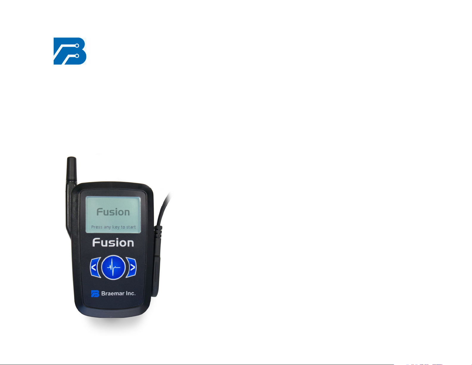
Fusion
Wireless
Recorder
Page 2

Braemar Limited Warranty
Braemar products are warranted to be free from manufacturing and
material defects for a period of one (1) year from the date of shipment
from Braemar to the original purchaser.
Excluded from this warranty are expendable supply items including, but
not limited to, electrodes, lead wires, patient cables and batteries. This
warranty does not apply to any product which Braemar determines has
been modified or damaged by the customer.
Except for the express warranties stated above, Braemar disclaims
all warranties including implied warranties of merchantability and
fitness. The stated express warranties are in lieu of all obligations
of liabilities on the part of Braemar for damages, including but not
limited to, special indirect or consequential, arising out of or in
connection with the use or performance of Braemar products.
Any action for breach of warranty shall be commenced within one (1)
year of said breach or be forever barred. Any repairs made to the
product which are not covered by the warranty shall be billed to the
customer.
Document Number: 600-0645-00
Revision: 05
Date: February 2009
Page 3

Fusion Wireless Recorder
1
2
Fusion Wireless Recorder
Table of Contents
Overview...................................................................................................2
Precautions...............................................................................................2
Disclaimer.................................................................................................3
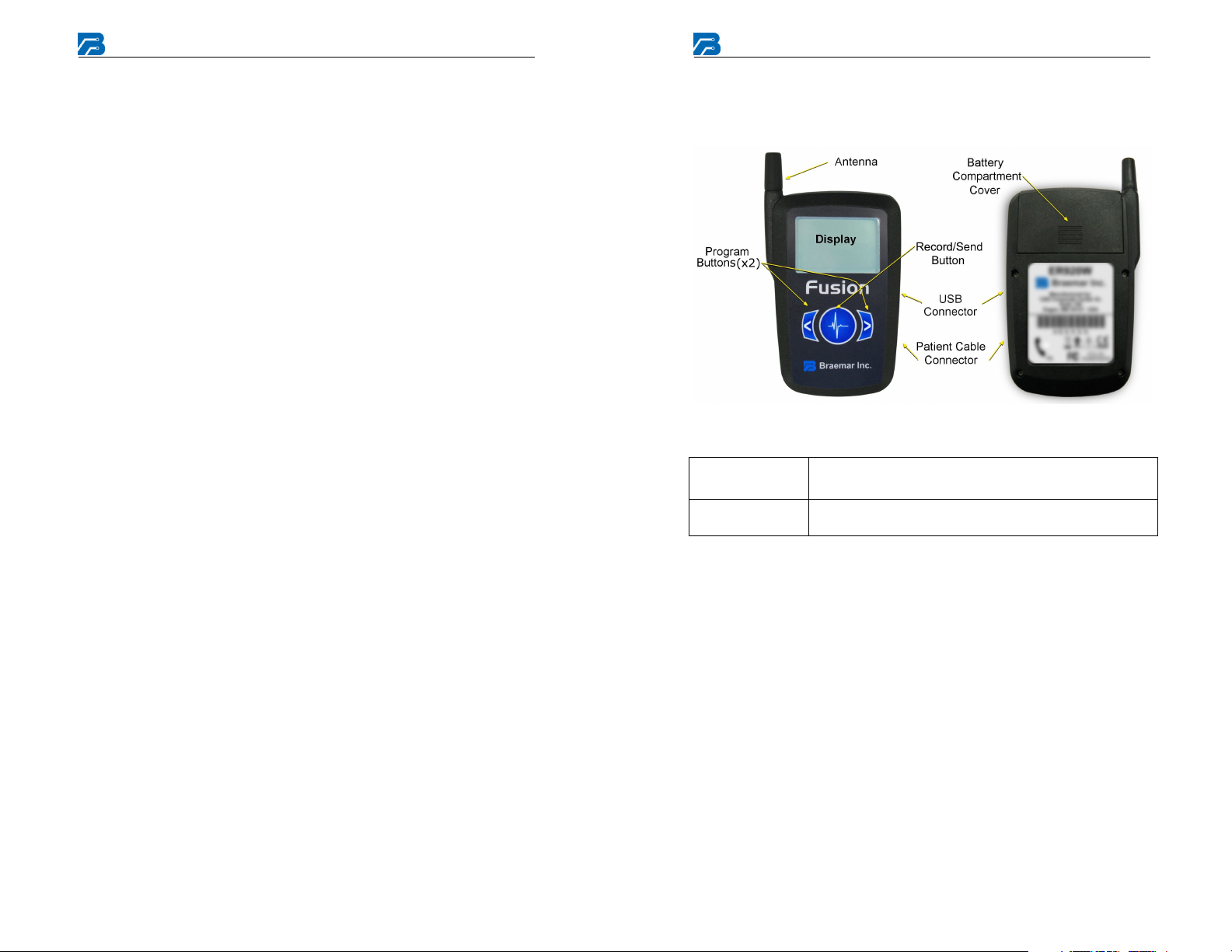
Recorder Components..............................................................................4
Setup Steps ..............................................................................................5
Electrode Application and Placement .......................................................5
1/2/3 Channel Electrode Placement .........................................................6
3 Channel (5 lead) Electrode Placement (1st option)………………7
3 Channel (5 lead) Electrode Placement (2nd option)………………8
Recorder Preparation ...............................................................................9
Establishing the Home Link ....................................................................13
Troubleshooting (page 1 of 2).................................................................16
Service and Maintenance .......................................................................18
Service Items and Accessories...............................................................18
Equipment Symbols................................................................................19
Specifications .........................................................................................20
Overview
The Fusion Wireless Recorder is a battery operated, solid state recorder
designed to record symptomatic heart arrhythmias.
The Fusion Recorder provides up to 20 days of total recording time for 3
channels, 30 days of total recording time for 1 or 2 channels with the AA
Lithium battery pack.
The Fusion Recorder is enhanced with Arrhythmia Detection firmware
which will capture and automatically record asymptomatic, infrequent, or
elusive heart arrhythmia events such as Bradycardia, Tachycardia, Pause,
and Atrial Fibrillation.
Once an event is recorded, the event ECG is automatically transferred via
a digital cellular link. If a digital cellular link is not available, the event
ECG can be transferred by Bluetooth to a phone line via a Home Link
Bluetooth modem.
Precautions
A. Patient leads must be removed from electrodes before defibrillation.
B. Observe local laws for disposal of batteries.
C. Do not leave the batteries in the Recorder when it is not in use.
Damage from corrosion could result.
D. Patient should be instructed to avoid close proximity to heavy
electrical equipment or other sources of electromagnetic
interference.
E. Use only the provided battery pack. Observe polarity when inserting
F. Recorder is not for infant use.
G. No automatic analysis algorithm can replace data review by a
qualified physician. Review and confirmation of analysis results is
required.
H. Patients should seek immediate medical attention if they experience
symptoms that concern them.
Electromagnetic Emissions.....................................................................21
Electromagnetic Immunity ......................................................................21
Recommended Separation Distances ....................................................24
Page 4
Fusion Wireless Recorder
3
4
Fusion Wireless Recorder
Disclaimer
Operation of the Fusion Recorder may be subject to governmental and
business restrictions, including but not limited to air travel and hospital
visitations.
Additional equipment classification information as required in EN 60601-1
A. EQUIPMENT not suitable for use in the presence of a
FLAMMABLE ANAESTHETIC MIXTURE WITH AIR OR WITH
OXYGEN OR NITROUS OXIDE
B. IPX0 Ordinary Equipment (enclosed equipment without protection
against ingress of water)
C. Internally Powered Equipment
D. Mode of Operation - Continuous Operation
Recorder Components
Batteries
Patient Cable
Caution: U.S. Federal law restricts this device to sale by or on the
order of a physician.
3.6V AA Lithium battery pack. Insert into battery
compartment observing polarity symbols.
To adjust, move plastic slip rings up or down to keep
leads together. To lengthen, pull leads apart.
Page 5
Fusion Wireless Recorder
5
6
Fusion Wireless Recorder
Setup Steps
This manual is designed to allow a technician to follow the instructions
page by page to setup the Fusion Recorder. Here is the general layout:
1. Connect leads and electrodes to patient.
2. Prepare Recorder for recording.
A. Choose/Setup program options you want to use.
B. Erase all previous data.
3. Connect Patient Cable to Recorder.
Electrode Application and Placement
For each electrode lead wire:
1. Snap the electrode onto the lead wire.
2. Remove the protective backing from the adhesive side of the
electrode.
3. Apply the electrode to the patient’s skin per Electrode Placement
diagram in this manual or as instructed by the physician.
Notes:
A. It is recommended that trained medical personnel instruct the
patient in the proper application of electrodes.
B. Use good quality long term electrodes. Braemar recommends
the use of low impedance Holter electrodes. Instruct patient to
apply fresh electrodes regularly. (Usually on a daily basis.)
C. Proper preparation of the patient's skin is absolutely essential
for obtaining a quality ECG recording. The skin surface where
the electrodes will be placed should be cleaned with alcohol,
allowed to dry, and abraeded.
D. Any loose electrode needs to be replaced.
1/2/3 Channel Electrode Placement
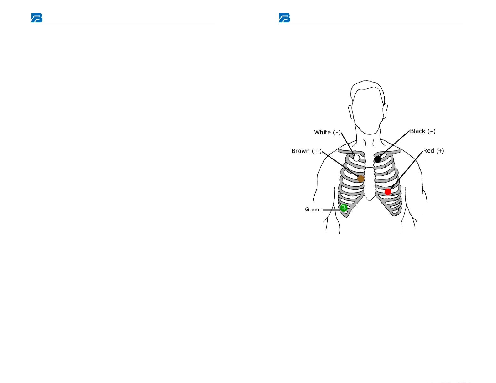
This is a typical electrode placement. Refer to Analysis System software
and the physician for recommended positioning.
1, 2, and 3 Channel Electrode Placement
Channel 1 = Red (1+), White (1-),
Green (ground (RL))
Channel 2 = Red (1+), White (1-/2-), Black (2+),
Green (ground (RL))
Channel 3 = Brown (1+), Red (1-/2-), Black (2+,3+),
White (3-), Green (ground (RL))
Page 6
Fusion Wireless Recorder
7
8
Fusion Wireless Recorder
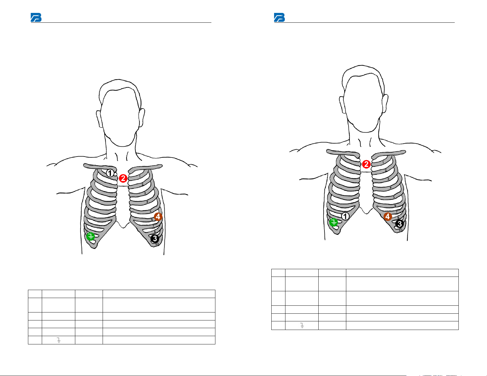
3 Channel (5 lead) Electrode Placement (1st option)
Five color-coded leadwires are used to create a 3-channel ECG
recording. This is a typical electrode placement. Refer to your Analysis
System software and the physician for a recommended position.
3 Channel (5 lead) Electrode Placement (2nd option)
Five color-coded leadwires are used to create a 3-channel ECG
recording. This is a typical electrode placement. Refer to your Analysis
System software and the physician for a recommended position.
Figure 4 - 5 Lead Electrode Placement
5 Lead Electrode Placement
# Channel Color Location
1 3- White
Next to the right Manubrium border on the
Clavicle
2 1-, 2- Red Centered on the Manubrium
3 2+, 3+ Black Lower left rib margin over bone.
# Channel Color Placement
1 3- White
2 1-, 2- Red
Right side below the V1 position, at the
bottom of the rib cage
Center on the Manubrium, the top of the
sternum
3 2+, 3+ Black Left side at the V5 position, on a rib
4 1+ Brown Left side at the V3 position, on a rib
5
Green Right side opposite V5 position.
4 1+ Brown Left Anterior Auxiliary line on the 6th rib
5
Green Lower right rib margin over bone.
Page 7
Fusion Wireless Recorder
9
10
Fusion Wireless Recorder
Recorder Preparation
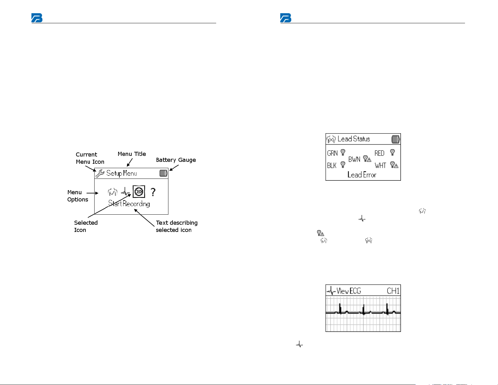
1. General setup: Remove the Patient Cable if it is connected to
the Recorder. Open the battery compartment by sliding battery
door upward. Install the AA Lithium battery pack. Observe proper
battery polarity. The Recorder will sound rising tones after
completion of power up. After a few seconds, the splash screen will
appear. If a patient cable is not connected, a message indicating that
a cable is not connected will be displayed. Please insert a patient
cable to exit the splash screen and enter the Setup (New Recording)
Menu with the battery level in the upper right corner. The battery
level should be near 100%. All button presses should beep to
provide feedback for the user. The backlight for the display is on
while accessing the Menus, after recording a manual event, or after
receiving a text message. The backlight will remain off during
normal recording.
2. Erase Data:
If the Recorder still has data and the Recording is Complete, you
must erase all the data before setting up the Recorder for the next
patient.
A. Remove the Patient Cable.
B. Press the Left and Right buttons together and it will prompt you
to Erase Data.
C. Press the Enter button to erase the data. The display will have
the message “Recorder Empty”.
D. Insert the patient cable, press the Left and Right buttons
together, and the Setup (New Recording) Menu will appear with
the battery level in the upper right corner. The battery level
should be near 100%.
If the Recorder is still recording data, you must stop the recording
and erase all the data before setting up the Recorder for the next
patient.
A. Remove the Patient Cable.
B. Press the Left and Right buttons together and it will prompt you
if you want to Stop Recording.
C. Press the Enter button to stop recording the data and the
Recording Complete screen will appear.
D. Continue to erase the data by following the steps above.
3. Preliminary Setup:
At this time, the patient leads should be connected to the electrodes
and the electrodes should be connected to the patient.
Using the left and right arrow buttons, select the “ ” to check the
lead status then press the “ ” button, also called Enter, to select the
menu option. Any leads are disconnected will have a caution
symbol (“ ”) next to it and a “Lead Error” will be displayed.
Also, the “ ” changes to “ ” when there is lead loss in the
Current Menu icon and in the Setup (New Recording) Menu. At
least two leads must be connected to see the Lead Status. If there
are less than two leads present, a “No Cable” message is displayed.
Press the Enter button to return to the Setup (New Recording) Menu.
Lastly, use the left and right buttons to select the View ECG option,
“ ”, and press Enter to check the ECG measurements. You can
Page 8
Fusion Wireless Recorder
11
12
Fusion Wireless Recorder
look through all the available channels by pressing the Left and
Right buttons. If any channel is not available due to an error
detecting a lead, a “Lead Error” message will be displayed for only
those affected channels. If the cable becomes disconnected, all
channels will display “No Cable”.
To enter or exit zoom mode, press the Left and Right buttons
together for one second. A magnifying glass will appear next to the
channel number in the upper right corner. Pressing the Right button
will increase the amplitude of the signal, while pressing Left will
decrease the amplitude of the signal. Pacer pulse marks are
displayed with a paced signal below the trace to indicate each
detection of a pacer pulse.
If the data looks good, press the Enter button to return to the Setup
(New Recording) Menu.
If necessary, use the right and left arrow buttons to select the “?” and
press Enter for the About Screen. This screen displays the Model,
Serial Number, Recorder Firmware version, the current Time, and
the current Date.
General notes:
A. Lead loss and Pacer detection is on all the time.
B. The number of channels a Patient Cable contains will determine
the number of channels the Recorder will record.
C. Although the device detection algorithms are very sophisticated,
there is no guarantee that the device will catch all episodes of
arrhythmia.
4. Programming the Fusion Recorder: The Fusion recorder is
preprogrammed from the factory for default settings. The device is
fully programmable through the Fusion Wireless Monitoring System
Software. Please refer to the Fusion Wireless Monitoring System
Software for programming capabilities and options.
5. The Recorder is ready to record data.
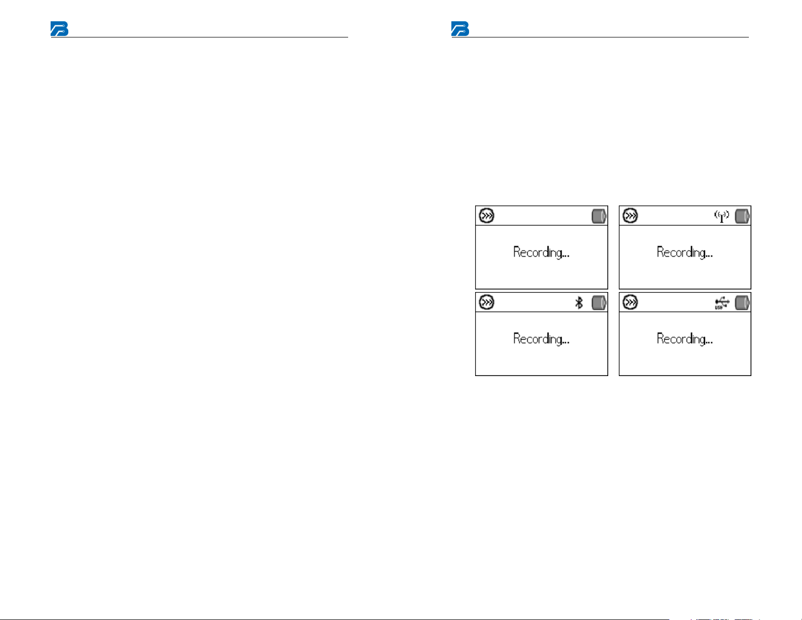
Once all setup is complete, start the recording. The Recording
screen should now be displayed. Depending on the connection
status to the server, the Recording screen could be displayed in the
following way:
Page 9
Fusion Wireless Recorder
13
14
Fusion Wireless Recorder
Establishing the Home Link
In accordance with FDA directive, Fusion Wireless Monitoring with
patient alarm conditions requires the establishment of a Home Link
alternative to cellular data communications. The Fusion Recorder kit
contains Bluetooth wireless hardware that must be connected to a normal
RJ-11C telephone jack, typically located on the nightstand or where the
patient will spend most of their time during the procedure. Patients
inside the home location should be in Home Link wireless contact if they
are within approximately 100 feet of the system. Note: This modem has
an actual line of site range of 328 feet but due to walls and other
structural impedance the modem should be placed within 100 feet. After
installation of the Home Link, the patient will contact the monitoring
center to verify that the redundant data transfer system is functioning.
The Fusion Recorder and Home Link modem wireless connection are
already preset by the Braemar factory.
Follow the directions provided with the Home Link hardware to connect
the modem to the patient’s telephone line. After installation of the Home
Link, the patient will contact the monitoring center to verify that the
redundant data transfer system is functioning.
Patient Operating Instructions
The Recorder should be ready when you receive it from the technician.
If there are any problems, refer to the Troubleshooting section.
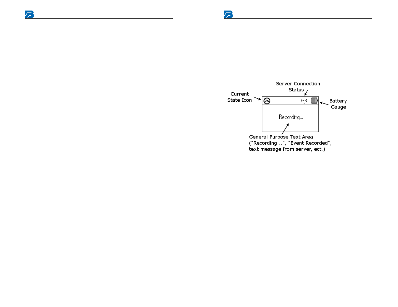
Display overview:
To Hookup:
1. Snap lead wires onto electrodes first, and then apply electrodes
according to physician instructions.
2. Reapply fresh electrodes daily.
3. Insert the Patient Cable into the Recorder.
4. The Recorder is now recording data as seen in the above screenshot.
Page 10

Fusion Wireless Recorder
15
16
Fusion Wireless Recorder
Record ECG: ECG to be marked will be described by the physician.
1. Press the RECORD/ENTER button until an audible tone is heard,
then release.
2.
Hold as still as possible during recording, which should only last a
few seconds, but continue breathing.
Automatic Recording:
If an event is detected, the Recorder will silently record and transmit the
event to the monitoring center for further review.
Note about TEXT Messaging:
The Fusion Wireless Monitoring System Software can provide text
messaging back the Fusion Recorder. Messages up to 3 lines with 32
characters per line can be displayed on the LCD of the Fusion Recorder
to allow communications back to the patient. A TEXT message received
by a recorder will initiate an audible alert of three beeps in rapid
succession. The alert will repeat every 10 minutes until the patient
presses one the arrow keys or is silenced by the monitoring center. The
message shall be displayed continuously until cleared by the monitoring
center. The patient is not able to clear the message unless the batteries
are removed.
To Send:
In most cases, events are automatically downloaded to the receiving
center via digital cellular link. If an appropriate cellular signal is not
present for the transmission to start, the recorder will automatically
connect to the Home Link Bluetooth modem. There isn’t any patient
interaction required for this transmission to occur.
To Download via USB:
Once the recording is finished, remove the patient cable from the
recorder. Connect the recorder to a PC running at the service center.
Software on the PC will download the ECG as needed. There is no
patient interaction with USB and USB cables cannot be connected while
a patient cable is connected.
Troubleshooting (page 1 of 2)
Symptom Recommended Solution
No display
Will not record
Recorder stops recording
Ensure batteries are inserted with correct polarity.
Ensure RECORD button has been pressed.
Ensure Patient Cable is inserted completely.
Page 11

Fusion Wireless Recorder
17
18
Fusion Wireless Recorder
Troubleshooting (page 2 of 2)
Noise artifact on recorded
ECG at patient location
Rising tone
Electrodes must be securely attached to patient.
Patient should remain still while recording.
Replace Patient Cable. Pulling on lead wires may damage
cable.
Verify the recording did not take place near a source of
electromagnetic interference (fluorescent lights, computer
monitors, or household appliances).
Move electrodes slightly to the right or left of the original
location.
Ready to record
Service and Maintenance
Cleaning
Cleaning should occur before each patient use and more frequently if
needed.
Remove the batteries before cleaning the recorder. Clean the battery
terminals with a soft dry cloth. Dampen a soft cloth with mild detergent
and water to clean the recorder, lead wires, and belt clip.
Remove any adhesives from the patient lead wires with an adhesive tape
remover solution or swab. Use a mild disinfectant. Do not use alcohol
or acetone on the lead wires since they could stiffen and the insulating
plastic could crack.
Service
If there is a problem with the Recorder, review the problem descriptions
and solutions listed on the next page. If additional assistance is required
contact customer support via phone, Fax or E-mail listed below. Call
customer support before returning a Recorder to make shipping
arrangements.
A. Note there isn’t any preventative inspection or maintenance that
can be performed by the end user.
Service Items and Accessories
Note: Only authorized accessories are
permitted.
Description Part Number
Patient Cable, 3 channel, 5 lead 350-0302-00
Patient Cable, 2 channel, 4 lead 350-0302-01
Patient Cable, 1 channel, 3 lead 350-0302-02
Patient Cable, 1 channel, 2 lead 350-0302-03
Patient Cable, 2 channel, 3 lead 350-0302-04
Recorder belt clip / Holster 100-1910-001
Operator manual 600-0645-00
AA Lithium Battery Pack 350-0294-00
USB 2.0 Data Cable
200-2792-001
Page 12

Fusion Wireless Recorder
19
20
Fusion Wireless Recorder
Equipment Symbols
Symbol Description
Type B Applied Part
Consult manual
SN
0086
Serial Number
Complies with the Medical Device Directive of the
European Union.
Waste Electrical and Electronic Equipment (WEEE)
It is the responsibility of the end user to dispose of
this equipment at a designated collection point for
recycling.
Date of Manufacture
Bluetooth trademark indicating conformity to
specifications
Manufacturer:
Braemar, Inc.
1285 Corporate Center Drive, Suite 150
Eagan, MN 55121 USA
Phone: 800.328.2719
Contact Braemar for further technical information.
Authorized European Rep:
QNET BV
Hommerterweg 286
6436 AM Amstenrade
The Netherlands
Specifications
Functional
Fusion 1, 2, or 3 channel
Sample rate 256 samples per second
User interface LCD display and sound
Memory
Max total record time
One channel 30 days
Two channel 30 days
Three channel 20 days
Type Flash
Data retention Non-volatile
Physical
Dimensions 4.1"x 2.25"x .75"
Weight with batteries 5.5 oz.
Enclosure Molded plastic
Operating position Any orientation
Electrical
Input impedance 10M min.
CMR ratio 60dB
AC signal range +/- 5mV
DC signal range +/- 300mV
Resolution 12 bits
Frequency response .05Hz to 80Hz
Environmental
Operating temperature
Non-operating temperature
Operating humidity 10% to 95% without condensation
Non-Operating humidity 5% to 95% without condensation
Battery
Type (2) AA Lithium Thionyl
Life 500 transmissions
Remove batteries during storage
Warranty 12 months from shipment
0°C to +45°C
-20°C to +65°C
Page 13
Fusion Wireless Recorder
21
establishments, including domestic
Power frequency
22
Electromagnetic Emissions
Fusion Wireless Recorder
Emissions test Compliance
RF emissions
Class B Fusion is suitable for use in all
CISPR 11
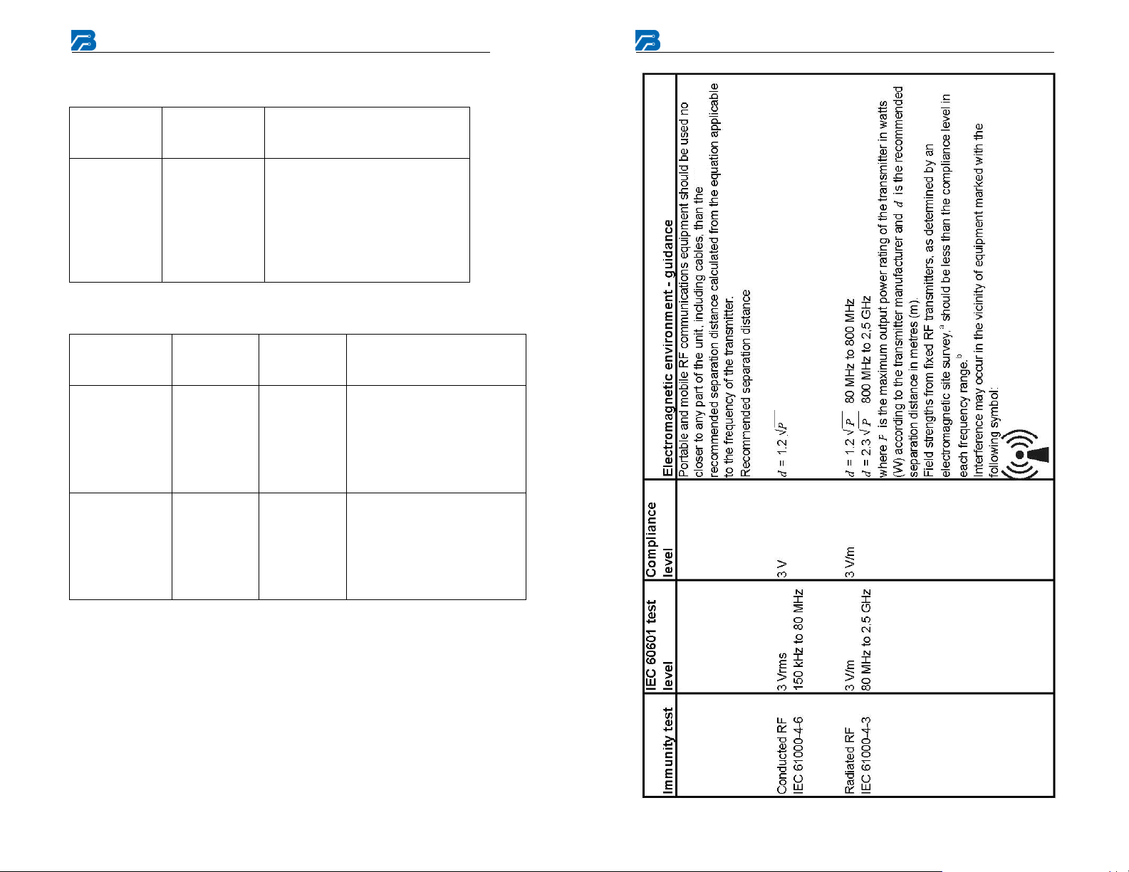
Electromagnetic Immunity
Immunity test
Electrostatic
discharge (ESD)
IEC 61000-4-2
(50/60 Hz)
magnetic field
IEC 61000-4-8
IEC 60601
test level
±6 kV contact
±8 kV air
3 A/m 3 A/m Power frequency magnetic
Electromagnetic
environment - guidance
establishments and those directly
connected to the public lowvoltage power supply network that
supplies buildings used for
domestic purposes.
Compliance
level
±6 kV contact
±8 kV air
Electromagnetic
environment - guidance
Floors should be wood,
concrete or ceramic tile. If
floors are covered with
synthetic material, the relative
humidity should be at least
30% without condensation.
fields should be at levels
characteristic of a typical
location in a typical
commercial or hospital
environment.
Page 14
Fusion Wireless Recorder
23
24
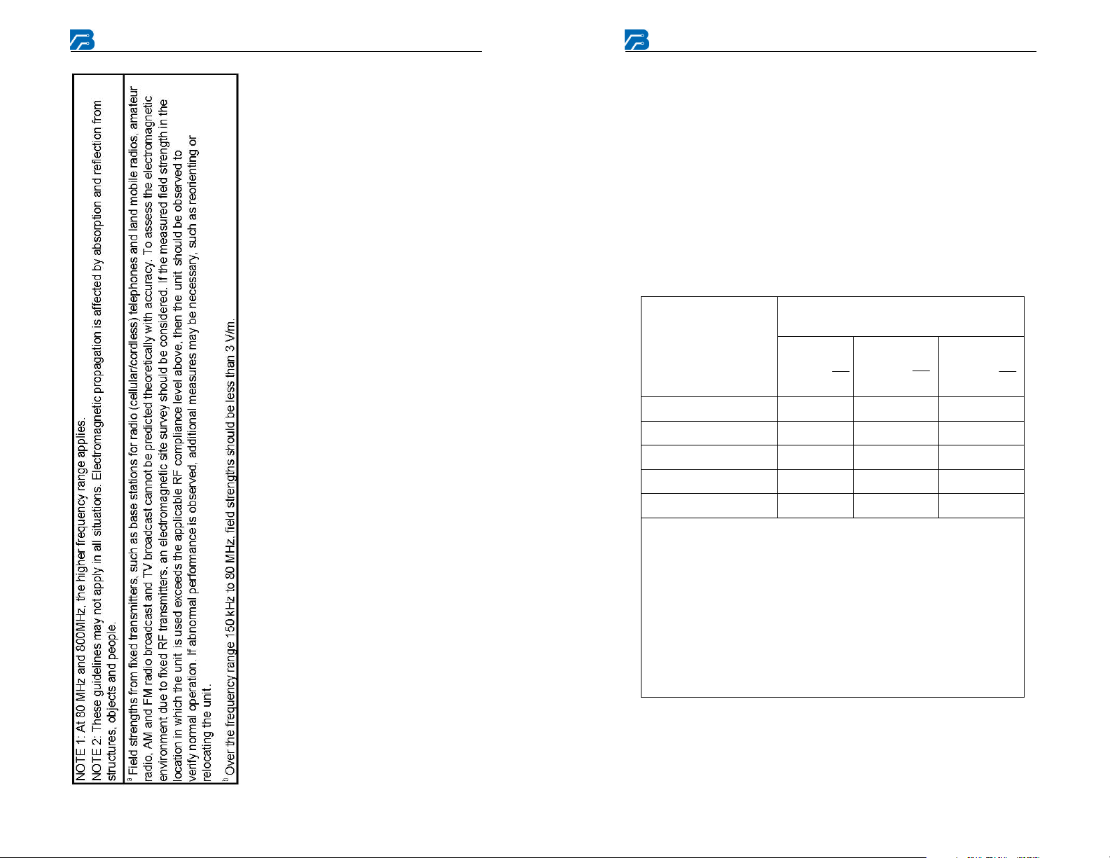
Electromagnetic propagation is affected by absorption and reflection
Fusion Wireless Recorder
Recommended Separation Distances
Refer to the following table for recommended separation distances
between Fusion and portable and mobile RF communications equipment.
Fusion is intended for use in an electromagnetic environment in which
radiated RF disturbances are controlled. The user of Fusion can help
prevent electromagnetic interference by maintaining a minimum distance
between portable and mobile RF communications equipment
(transmitters) and Fusion as recommended below, according to the
maximum output power of the communications equipment.
Rated maximum
output power of
transmitter
W
0,01 0,12 0,12 0,23
0,1 0,38 0,38 0,73
Separation distance according to
frequency of transmitter
150 kHz
to 80 MHz
d = 1.2 √ P
80 MHz
to 800 MHz
d = 1.2 √ P
800 MHz
to 2,5 GHz
d = 2.3 √ P
1 1,2 1,2 2,3
10 3,8 3,8 7,3
100 12 12 23
For transmitters rated at a maximum output power not listed above,
the recommended separation distance d in metres (m) can be
estimated using the equation applicable to the frequency of the
transmitter, where P is the maximum output power rating of the
transmitter in watts (W) according to the transmitter manufacturer.
NOTE1: At 80 MHz and 800 MHz, the separation distance for the
higher frequency range applies.
NOTE 2: These guidelines may not apply in all situations.
from structures, objects and people.
Page 15

Fusion Wireless Recorder
25
FCC Statements
NOTICE: This device complies with Part 15 of the FCC Operation
is subject to the following two conditions:
(1) this device may not cause harmful interference, and
(2) this device must accept any interference received,
including interference that may cause undesired
operation.
NOTICE:
Changes or modifications made to this equipment not expressly
approved by (manufacturer name) may void the FCC authorization
to operate this equipment.
NOTE: This equipment has been tested and found to comply with
the limits for a Class B digital device, pursuant to Part 15 of the
FCC Rules. These limits are designed to provide reasonable
protection against harmful interference in a residential installation.
This equipment generates, uses and can radiate radio frequency
energy and, if not installed and used in accordance with the
instructions, may cause harmful interference to radio
communications. However, there is no guarantee that interference
will not occur in a particular installation. If this equipment does
cause harmful interference to radio or television reception, which
can be determined by turning the equipment off and on, the user is
encouraged to try to correct the interference by one or more of the
following measures:
The internal wireless radio operates within guidelines found in
radio frequency safety standards and recommendations, which
reflect the consensus of the scientific community. Braemar Inc.
therefore believes the internal wireless radio is safe for use by
consumers. The level of energy emitted is far less than the
electromagnetic energy emitted by wireless devices such as
mobile phones SAR value of 0.522W/kg max.
However, the use of wireless radios may be subject to
governmental and business restrictions, including but not
limited to air travel and hospital visitations. If you are unsure
of restrictions, you are encouraged to ask for authorization before
turning on the wireless radio.
Radio Frequency radiation exposure Information
For body worn operation, this device has been tested and meets
the FCC RF exposure guidelines when worn in the pouch and
used with the Braemar accessories supplied or designated for
this product.
Use of other accessories may not ensure compliance with FCC
RF exposure guidelines.
NOTICE: This device complies with part 15 of the FCC rules and
with RSS-210 of Industry Canada. Operation of this device is
subject to the following two conditions: (1) This device may not
cause harmful interference; (2) This device must accept
interference received including interference that may cause
undesired operation. Changes or modifications made to this
equipment not expressly approved by (manufacturer name) may
void the FCC authorization to operate this equipment.
•
Reorient or relocate the receiving antenna.
•
Increase the separation between the
equipment and receiver.
•
Connect the equipment into an outlet on a
circuit different from that to which the receiver
is connected.
•
Consult the dealer or an experienced radio/TV
technician for help.
Page 16

Braemar Inc.
1285 Corporate Center Drive, Suite 150 Fax: 651.286.8630
Eagan, MN 55121 USA E-Mail: [email protected]
Copyright 2008, Braemar Inc. All rights reserved
Phone: 800.328.2719
 Loading...