

Page 1
SLV-DAT-PRO
User’s Guide
Part #107337
Rev. A
Page 2

Page 3

SLV-DAT-PRO
Impact Printer
User’s Guide
Installation and Start Up
Keypad Configuration
Forms Handling
Features and Profiles
Troubleshooting and Maintenance
Specifications
Default Tables
System Administration Features
ASCII Conversion Charts
ASCII Characters Sets
Escape Sequence Quick Reference
PCL Emulation
www.bradyid.com
Page 4

User’s Guide
ii
Copyright
This manual is copyrighted with all rights reserved. No portion of this manual may be copied
or reproduced by any means without the prior written consent of Brady Corporation.
While every precaution has been taken in the preparation of this document, Brady assumes no
liability to any party for any loss or damage caused by errors or omissions or by statements
resulting from negligence, accident, or any other cause. Brady further assumes no liability
arising out of the application or use of any product or system described, herein; nor any
liability for incidental or consequential damages arising from the use of this document. Brady
disclaims all warranties of merchantability of fitness for a particular purpose.
Brady reserves the right to make changes without further notice to any product or system
described herein to improve reliability, function, or design.
© 2004 Brady Corporation. All Rights Reserved.
Revision A, 07/2004
Firmware Version 1.0
Brady Corporation
6555 West Good Hope Road
P.O. Box 2131
Milwaukee, WI 53201
Main Switchboard: (800) 541-1686
(414) 358-6600
FAX: (800) 292-2289
Sales/Customer Support: (800) 537- 8791
Page 5

User’s Guide
iii
Preface
Thank you for selecting the SLV-DAT-PRO Single Tractor V-Throat printer.
Some of the procedures in this guide contain special notices that highlight important
information:
NOTES Indicate information that you should know to help your printer run
properly and efficiently.
CAUTIONS Indicate guidelines that, if not followed, can cause damage to
equipment.
WARNINGS Indicate a situation where there may be a danger to you.
The use of the terms right and left assume that you are looking at the front of the printer.
Page 6

User’s Guide
iv
Compliance
This device complies with part 15 of the FCC rules. Operation is subject to the following two
conditions:
1. This device may not cause harmful interference, and
2. This device must accept any interference received, including interference that may
cause undesired operation.
NOTE
This equipment has been tested and found to comply with the
limits for a Class A digital device, pursuant to Part 15 of the
FCC Rules. These limits are designed to provide reasonable
protection against harmful interference when the equipment is
operated in a commercial environment. This equipment
generates, uses, and can radiate radio frequency energy and, if
not installed and used in accordance with the instructions, may
cause harmful interference to radio communications. Operation
of this equipment in a residential area is likely to cause harmful
interference, in which case the user will be required to correct
the interference at his own expense.
WARNING
CHANGES OR MODIFICATIONS TO
THIS UNIT NOT EXPRESSLY APPROVED
BY THE PARTY RESPONSIBLE FOR
COMPLIANCE COULD VOID THE
USER'S AUTHORITY TO OPERATE THE
EQUIPMENT.
Page 7

User’s Guide
v
NOTE
When connecting the printer to a host computer system,
always use shielded interface cables. The use of non-shielded
interface cables is a violation of the FCC emissions limits for
a Class A computing device. Do not leave unterminated
interface cables connected to the printer.
This digital apparatus does not exceed the Class A limits for radio noise emissions from
digital apparatus set out in the Radio Interference Regulations of the Canadian Department of
Communications.
Cet appareil numérique n'émet pas de bruits radioélectriques dépassant les limites applicables
aux appareils numériques de la classe A prescrites dans le Règlement sur le Brouillage
Radioélectrique édicté par le Ministére des Communications canadien.
Ob gesetzliche Bestimmungen eingehatten werden, hängt von
der Anwendung geschirmter Kabel ab. Der Anwender ist für die
Anschaffung der passenden Kabel selbst verantwortlich.
DIESES GERÄT WURDE IM HINBLICK AUF DIE EINHALTUNG DER
FUNKENTSTÖRBESTIMMUNGEN SOWOHL ALS EINZELGERÄT ALS AUCH IM
SYSTEM (ZUR SIMULATION NORMALER EINSATZBEDINGUNGEN) ÜBERPRÜFF.
DENNOCH IST ES MÖGLICH, DA
ß DIESEN FUNKENTSTÖRBESTIMMUNGEN
UNTER GEWISSEN UNVORTEIILHAFFEN BEDINGUNGEN IN SYSTEMEN NICHT
ENTSPROCHEN WIRD. DER ANWENDER IST SELBST FÜR DIE EINHALTUNG DER
GESETZLICHEN BESTIMMUNGEN BEIM BETRIEB SEINER ANLAGE
VERANTWORTLICH.
Page 8

User’s Guide
vi
BESCHEINIOUNG DES HERSTELLERS/IMPORTEURS
Hiermit wird bescheinigt, da
ß der/die/das
SLV-DAT-PRO
(Gerdt, Typ, Bezeichnung)
in Übereinstimmung mit den Bestimmungen der Vfg 1046
(DIN-DVE-Norm bzw, EN-Norm bzw, BMPT-AmstblVfg 242/1991, 46/1992) funkentstört ist.
Dem Bundesamt für Zulassungen in der Telekommunikation wurde das Inverkehrbringen
dieses Gerätes angezeigt und die Berechtigung zur Überprufung der Serie auf die Einhaltung
der Bestimmungen eingeräumt.
(Name and Anschrift des Herstellers/Importeurs)
Diese Anzeige kann bei Geräten, die der EN 55014 bzw.
55015 entsprechen, entfallen
WARNING
Any alteration or modification to this equipment may cause non-compliance to:
WARNUNG
Jede Abdnderung oder Modifizierung dieses Gerdts kann eine Zuwiderhandlung gegen
folgende Bestimmungen darstellen:
ADVERTENCIA
Cualquier alteración o modificación de este equipo podría resultar en la infracción de:
ATTENTION
Tout changement ou modification apporté à cet équipement peut entraîner sa non conformité
au:
UL Safety Standard 1950
CSA Safety Standard C22.2 No. 950
FCC Regulations for Class A Computing Devices
VDE EMI Regulations Vfg 1046, Class A (GS marked units only)
EN50082-1 Class A Limits
EN60950
Page 9

User’s Guide
vii
CAUTION
The printer must have the correct line fuse installed for the selected input voltage.
VORSICHT
Im Drucker mu
ß eine, der gewählten Eingangsspannung entsprechende Sicherung installiert
sein.
PRECAUCION
El fusible instalado en la línea de la impresora debe ser el apropriado para la tensíon de
entrada.
ADVERTISSEMENT
L’imprimante doit être munie d’un fusible adapté au voltage d’entrée choisi.
***************************************************************************
WARNING
The operator must disconnect the printer from the A.C. power supply before performing any
corrective action procedure that requires reaching into the printer.
WARNUNG
Die Stromzufuhr zum Drucker mu
ß unterbrochen werden, bevor irgendwelche korrektiven
MaBnahman im Inneren des Geräts vorgenommen werden.
ADVENTERCIA
El usuario debe desconectar la impresora de la corriente altema AC antes de proceder con
cualquier arregio que requiera meter la mano dentro de la impresora.
ATTENTION
L’ opérateur doit débrancher l'imprimante de la source d'alimentation C.A avant de réaliser
toute procédure de correction manuelle dans l'imprimante.
Page 10

User’s Guide
viii
WARNING
Changes or modifications to this unit not expressly approved by the party responsible for
compliance could void the user's authority to operate the equipment.
WARNUNG
Abänderungen oder Modifizierungen dieses Geräts dürfen nur mit ausdrücklicher
Genehmigung der für die Zulassung verantwortlichen Stelle vorgenommen werden. Verstö
ße
dagegen könnten den Widerruf der Zulassung des Geräts zur Folge haben.
ADVERTENCIA
Los cambios o modificaciones llievados a cabo en esta unidad, no aprobados explicitamente
por la parte responsable de cumplir con el regiamento, podrían invalidar la autoridad del
usuario para utilizar el equipo.
ATTENTION
Les changements ou modifications apportés cette unité non expressément approuvés par la
parte responsable de la conformité peuvent annuler I'autorité de l' utilisateur à operér 1'
équipement.
***************************************************************************
WARNING
Connect 115v (230v) units to 115v (230v) outlets only!
WARNUNG
115v (230v)-Geräte nur an 115v (230v)-Steckdosen anschlie
ßen!
ADVERTENCIA
iConecte unidades de 115v (230v) unicamente a tomas de 115v (230v)!
ATTENTION
Brancher les unités 115v (230v) uniquement sur des prises 115v (230v)!
Page 11

User’s Guide
ix
WARNING
The printhead gets hot during use. Wait until the printhead is cool before handling the
printhead.
WARNUNG
Der Druckkopf erhitzt sich, während das Gerät in Betrieb ist. Bevor Arbeiten am Druckkopf
durchgeführt werden, warten, bis dieser abgekühlt ist.
ADVERTENCIA
La cabeza impresora se recalienta con el uso. Esperar hasta que se enfríe antes de tocarta.
ATTENTION
La tête d' impression chauffe pendant l' usage. Attendre que la tête d'impression soit froide
avant de la manipuler.
***************************************************************************
WARNING
Connecting this equipment to an ungrounded power receptacle can result in the risk of
electrical shock.
WARNUNG
Dieses Gerät darf keinesfalls an eine ungeerdete Steckdose angeschlossen werden. Es besteht
Elektroschockgefahr.
ADVERTENCIA
El enchufar este equipo a una toma de corriente no conectada a tierra podría resultar en riesgo
de una descarga eléctrica.
ATTENTION
Brancher cet équipement á une prise non reliée à la terre peut provoquer une électrocution.
Page 12

User’s Guide
x
WARNING
Make certain the printer is disconnected from the A.C. power supply before reaching into the
printer to perform any cleaning or maintenance task.
WARNUNG
Die Stromversorgung des Druckers mu
ß unterbrochen sein, ebe irgendwelche Reinigungs-
oder Wartungsarbeiten vorgenommen werden.
ADVERTENCIA
Asegúrese de que la impresora esta desconectada de la corriente altema AC antes de
introducer la mano en su interior para cualquier labor de limpieza o mantenimiento.
ATTENTION
S' assurer que l' imprimante soit débranchée de la source d'alimentation C.A avant de réaliser
des tâches de nettoyage ou d'entretien manuelles.
***************************************************************************
SILICON SOFTWARE
1989 Ready Systems Corp. All rights reserved. Unpublished-rights
reserved under the copyright laws of the United States.
RESTRICTED RIGHTS LEGEND
Use, duplication or disclosure by the Government is subject to
restrictions as set forth in subparagraph (c)(1)(i) of the Rights in
Technical Data & Computer Software clause at DFARS
252.227-7013. READY SYSTEMS, 470 PORTRERO AVENUE
SUNNYDALE, CA 94806
Page 13

User’s Guide
xi
Brady Warranty
Brady products are sold with the understanding that the buyer will test them in actual use and
determine for him or herself their adaptability to his/her intended uses. Brady warrants to the
buyer that its products are free from defects in material and workmanship, but limits its
obligations under this warranty to replacement of the product shown to Brady’s satisfaction to
have been defective at the time Brady sold it. This warranty does not extend to any persons
obtaining the product from the buyer.
THIS WARRANTY IS IN LIEU OF ANY OTHER WARRANTY, EXPRESS OR IMPLIED
INCLUDING, BUT NOT LIMITED TO ANY IMPLIED WARRANTY OF
MERCHANTABILITY OR FITNESS FOR A PARTICULAR PURPOSE, AND OF ANY
OTHER OBLIGATIONS OR LIABILITY ON BRADY’S PART. UNDER NO
CIRCUMSTANCES WILL BRADY BE LIABLE FOR ANY LOSS, DAMAGE, EXPENSE
OR CONSEQUENTIAL DAMAGES OF ANY KIND ARISING IN CONNECTION WITH
THE USE, OR INABILITY TO USE, BRADY’S PRODUCTS.
Technical Support
Choose one of the following options to contact system support provided by Brady
Corporation:
U.S. and Canada
Phone: (800) 643-8766, Monday - Friday 7:00 a.m. - 6:00 p.m. (CST).
Fax: (414) 358-6767.
E-Mail: tech_support@bradycorp.com
.
Assistance is available 24 hours per day / 7 days per week. Go to: www.bradyid.com
, and
then select Knowledge Base from the left-hand panel.
Page 14

Page 15

User’s Guide
i
Table of Contents
Title Page
1. Installation and Start Up .........................................................................1-1
1.1 Introduction ...............................................................................................................1-1
1.2 Quick Start Up Procedure..........................................................................................1-2
1.3 Unpack the Printer.....................................................................................................1-4
1.4 Choosing a Place for the Printer................................................................................1-5
1.5 Printer Parts...............................................................................................................1-6
1.6 Install the Power Cord...............................................................................................1-9
1.7 Install the Ribbon Cartridge ....................................................................................1-11
1.8 Printer Self Test.......................................................................................................1-18
1.9 Interfacing ...............................................................................................................1-20
1.10 RS-232 and RS-422 Serial Interface Configuration................................................1-22
2. Keypad Configuration .............................................................................2-1
2.1 Keypad Configuration ...............................................................................................2-1
2.2 Ready LED................................................................................................................2-2
2.3 On/Off Line Key Function ........................................................................................2-3
2.4 LCD Display..............................................................................................................2-6
3. Forms Handling ......................................................................................3-1
3.1 Recommended Types and Sizes................................................................................3-1
3.2 Paper Paths ................................................................................................................3-2
3.3 Load Forms................................................................................................................3-3
3.4 Top of Form Adjustment.........................................................................................3-12
(Adjusting First Printline Location) .................................................................................3-12
3.5 Tear Off Adjustment ...............................................................................................3-14
3.6 Form Thickness Adjustment....................................................................................3-17
3.7 Heavy Forms Adjustment........................................................................................3-20
3.8 Changing From Main Paper Path to Alternate Path ................................................3-21
3.9 Changing From Alternate Paper Path to Main Paper Path ......................................3-23
3.10 Paper Out Condition................................................................................................3-24
3.11 Automatically Changing Paper Paths On Paper Out...............................................3-25
3.12 Selecting Paper Paths Using the Profile Key ..........................................................3-26
3.13 Selecting Paper Paths From the Host Computer Using DPCL Command.............3-28
Page 16

User’s Guide
ii
4. Features and Profiles............................................................................. 4-1
4.1 Features..................................................................................................................... 4-1
4.2 Profiles......................................................................................................................4-2
4.3 Setup Mode Key Functions....................................................................................... 4-4
4.4 LCD Display.............................................................................................................4-6
4.5 Profile Feature Listing .............................................................................................. 4-7
4.6 Changing Features in a Profile.................................................................................. 4-8
4.7 User Programmable Features.................................................................................. 4-11
5. Troubleshooting and Maintenance......................................................... 5-1
5.1 Scheduled Maintenance ............................................................................................5-1
5.2 Error Message...........................................................................................................5-3
5.3 Printer Diagnostics.................................................................................................... 5-8
5.4 Troubleshooting......................................................................................................5-16
5.5 Troubleshooting Table............................................................................................ 5-17
Page 17

User’s Guide
iii
Appendices Page
A. Printer Specifications............................................................................. A-1
A.1 Printer Characteristics ..............................................................................................A-1
A.2 Emulations................................................................................................................A-1
A.3 Font Specifications ...................................................................................................A-2
A.4 Paper Feed Specifications.........................................................................................A-4
A.5 Forms Mode Change ................................................................................................A-5
A.6 Communications Interface........................................................................................A-5
A.7 Operator Panel Functional Description ....................................................................A-6
A.8 Ribbon Cartridge/Drive ............................................................................................A-6
A.9 Physical ....................................................................................................................A-6
A.10 Electrical...................................................................................................................A-7
A.11 Shock and Vibration.................................................................................................A-7
A.12 Environmental ..........................................................................................................A-7
A.13 Compliances .............................................................................................................A-8
B. Interface Specifications ......................................................................... B-1
B.1 Parallel Interface.......................................................................................................B-1
B.2 Parallel Interface Enable/Disable ............................................................................. B-6
B.3 RS-232 Serial Interface ............................................................................................ B-7
B.4 Serial Interface Selection........................................................................................ B-10
C. Default Tables ....................................................................................... C-1
C.1 Menu 1: Page Format ............................................................................................... C-1
C.2 Menu 2: Forms Control ............................................................................................C-2
C.3 Menu 3: Personality..................................................................................................C-2
C.4 Menu 4: Printer Control ...........................................................................................C-3
C.5 Menu 5: Serial Interface ...........................................................................................C-4
C.6 Menu 6: Parallel Interface ........................................................................................C-4
C.7 Menu 7: Profile Control ...........................................................................................C-5
C.8 Menu 8: Form Thickness Control.............................................................................C-5
C.9 Menu 9: Diagnostics................................................................................................. C-6
C.10 Menu 10 System Control.......................................................................................... C-7
Page 18

User’s Guide
iv
D. System Administration Features ............................................................D-1
D.1 Features Available In System Control Menu........................................................... D-1
D.2 Menu 10: System Control ....................................................................................... D-2
D.3 Key Functions That Can Be Locked ........................................................................ D-5
E. ASCII Conversion Chart......................................................................... E-1
F. ASCII Character Sets............................................................................. F-1
F.1 ASCII Character Sets................................................................................................F-1
F.2 7 Bit ASCII Character Set.........................................................................................F-2
F.3 IBM Code Page 437 Symbol Set .............................................................................. F-4
F.4 IBM Code Page 850 Symbol Set .............................................................................. F-6
F.5 Epson Italic Symbol Set............................................................................................F-8
F.6 Epson Graphics Symbol Set....................................................................................F-10
F.7 Epson Italic Graphics Symbol Set ..........................................................................F-12
F.8 DEC Supplemental Symbol Set ..............................................................................F-14
F.9 Nationality Overlay Character Set ..........................................................................F-16
G. Escape Sequence Quick Reference ..................................................... G-1
G.1 Epson FX ................................................................................................................. G-1
G.2 IBM Proprinter......................................................................................................... G-5
G.3 DEC LA-120............................................................................................................ G-8
G.4 TI-885 (optional).................................................................................................... G-12
G.5 DS-180 ................................................................................................................... G-15
G.6 DPCL Command Sequence Summary................................................................... G-19
H. PCL H-1
H.1 Printer Command Language .................................................................................... H-1
H.2 Transparency Mode ................................................................................................. H-3
H.3 Task Mode ............................................................................................................... H-7
H.4 Sample Program for AIAG Label .......................................................................... H-10
Page 19

User’s Guide
1-1
1. Installation and Start Up
1.1 Introduction
This dot matrix impact printer provides high-speed performance, plus a rugged, round-theclock duty cycle, and flexibility to handle a number of printing applications.
Feature Highlights
• Straight through pin feed paper path for optimum forms handling.
• Nine wire ballistic printhead and flat metal print platen to assure legibility on every copy.
• Demand document printing.
• Automatic Form Thickness adjustment.
• Forms parking and reloading at the touch of a key.
• Four user-defined profiles for quick forms set up.
• Paper path selection by profile.
• Emulations: Epson FX, DEC LA 120, IBM Graphics, IBM Proprinter XL
• Options:
a. Second pin feed paper path
b. Cut sheet paper path
c. IBM Coax, IBM Twinax interfaces
d. Quiet cover set
e. Barcodes
f. Network Interface
Page 20

User’s Guide
1-2
1.2 Quick Start Up Procedure
The following is an abbreviated installation and start up procedure provided for users who are
already familiar with printer products. If you are not experienced with printers, follow all the
instructions in Chapter 1 for setting up the printer.
1. Place the printer on a suitable stand or countertop.
2. Install ribbon cartridge and power cord.
3. Turn printer on
4. Position left tractor with ‘Alignment’ mark on printer. Position front paper guides and
rear paper supports equally across the width of the form. Load 8 ½” paper into
tractors. (For cut sheet forms, set the left cut sheet guide to “0” and insert 8 ½” paper).
5. Press the Load Key (unnecessary for cut sheet path).
6. Open Keypad Door to enter Setup Mode.
7. Use the Quick Access Key, the Value keys, and the Enter Key to set margins.
8. Close the Keypad Door.
9. Press the Profile Key to save settings.
10. Open Keypad Door.
WARNING
CONNECT 115V UNITS TO 115V
OUTLETS ONLY! PRINTER DAMAGE
WILL RESULT!
Page 21
User’s Guide
1-3
11. Press the Feature Key. LCD should display “Self Test”.
12. Press the Enter Key.
When the Enter Key is pressed, the self test will begin printing. The self test may be stopped
by closing the Keypad Door or pressing the Enter Key.
CAUTION
IMPROPER MARGIN SETTING CAN
LEAD TO PRINTHEAD DAMAGE! DO
NOT PRINT OFF THE EDGE OF THE
FORM.
Page 22

User’s Guide
1-4
1.3 Unpack the Printer
Remove the following from the shipping carton:
• Dot Matrix Printer
• Power Cord
• Accessory Kit: User's Manual
Warranty Card
If any items are missing, please contact your distributor. Save the shipping carton and all
packing materials. These items will be needed in the event the printer must be shipped.
CAUTION
SHIPPING THE PRINTER IN ANY
CONTAINER OTHER THAN ITS
ORIGINAL PACKAGING MAY RESULT
IN SHIPPING DAMAGE AND MAY VOID
THE PRINTER WARRANTY.
Page 23

User’s Guide
1-5
1.4 Choosing a Place for the Printer
The printer weighs approximately 45 pounds. Its dimensions are:
• 17.0 inches (431 mm) wide x 15.7 inches (398 mm) deep x 11.3 inches (287 mm) high
(Standard model).
Location
1. To permit air flow and proper cooling, do not place anything closer than 2 inches
(50mm) to the printer.
2. Allow 6 inches to the right of the printer for access to the Form Thickness Adjustment
knob.
3. For continuous printing and accumulation of forms, allow sufficient room behind the
printer for cables and stacking forms.
4. Place the printer on a sturdy level surface and align lower front edge of printer with
table edge.
5. Locate the printer near a grounded power receptacle and use the power cord provided.
Do not use an extension cord to connect the printer.
6. Avoid the following:
• Direct sunlight or excessively illuminated areas
• Direct placement in front of air conditioning or heating vents
• Extreme high or low temperatures
• Exposure to excessive dirt or dust
• Exposure to vibration or mechanical shock
• Excessive humidity or condensation
Page 24

User’s Guide
1-6
1.5 Printer Parts
Four basic models of the printer are available:
• Standard straight tractor paper path with standard access cover.
Use the following illustrations to locate the major printer parts for each model. The standard
model is used to illustrate most of the procedures in this manual.
Figure 1-1: External Printer Parts (Standard Model)
Page 25

User’s Guide
1-7
NOTE
Keypad assembly is not shown in order to
identify the printhead.
Figure 1-2: Internal Printer Parts (Standard Model)
Page 26
User’s Guide
1-8
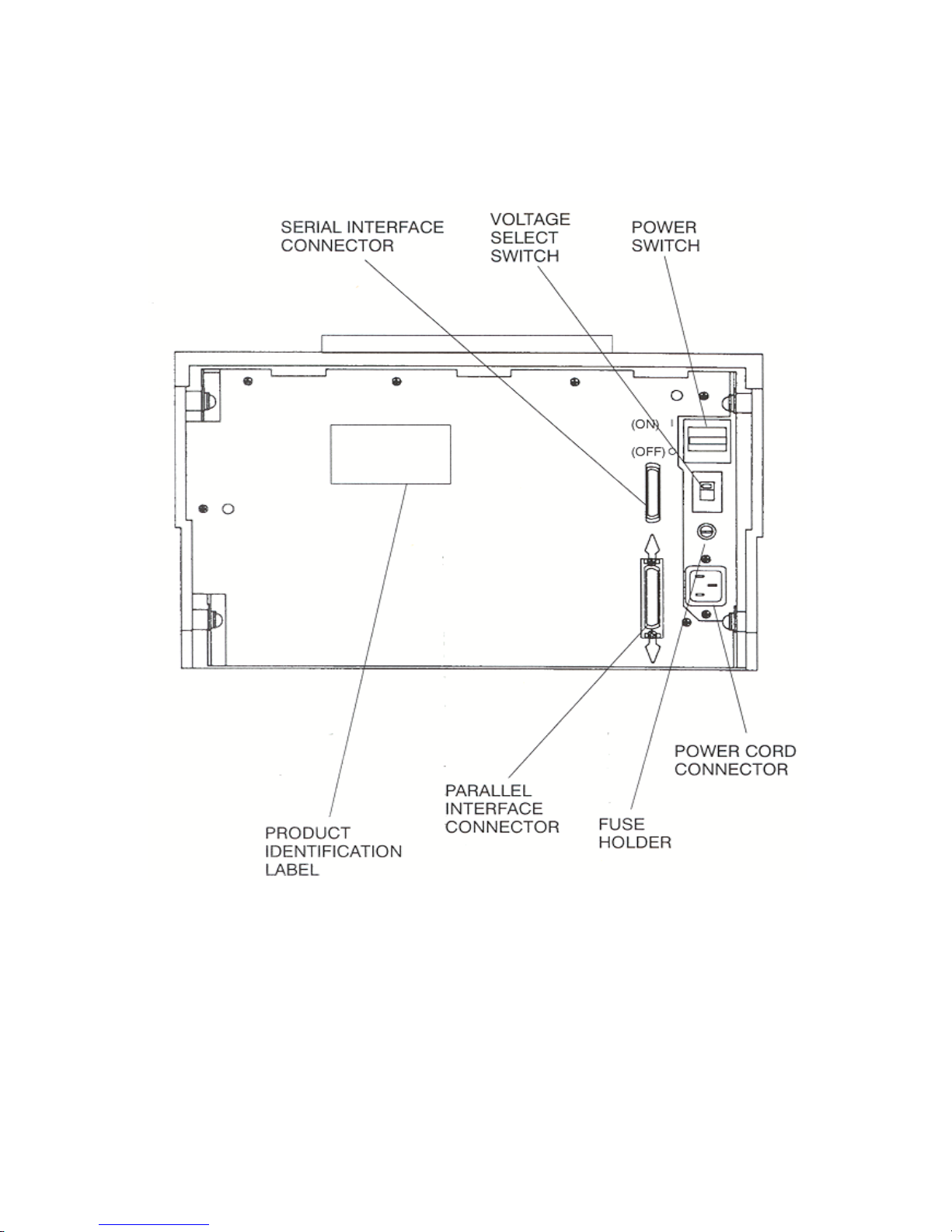
Figure 1-3: Back Printer Parts
Page 27
User’s Guide
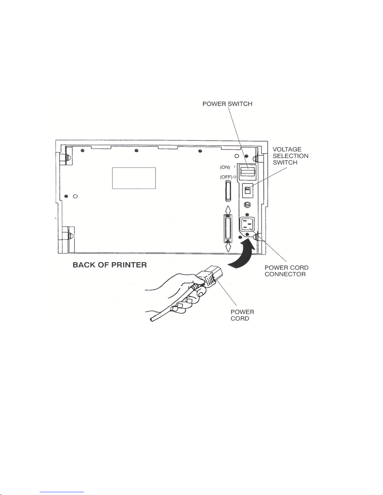
1-9
1.6 Install the Power Cord
1. Set the power switch to Off. (See Figure 1-4).
2. Install the power cord into the printer as shown in Figure 1-4.
3. Verify that voltage setting is correct for the application (115V-U.S.) (See Figure 1-4).
4. Install the plug end of the power cord into a grounded AC outlet. The voltage of the
AC power receptacle must match the voltage rating on the power cord receptacle label.
A grounded outlet must be used. Plugging the printer into an ungrounded outlet may
result in increased radio frequency noise generation, erratic printer operation, or
electrical shock.
5. Set the power switch to ON. The alarm will sound 3 short tones and the printer will
display:
WARNING
CONNECTING THIS EQUIPMENT TO AN
UNGROUNDED POWER RECEPTACLE
CAN RESULT IN ELECTRICAL SHOCK.
Paper Out: Main
Page 28
User’s Guide
1-10
Figure 1-4: Install Power Cord
Page 29

User’s Guide
1-11
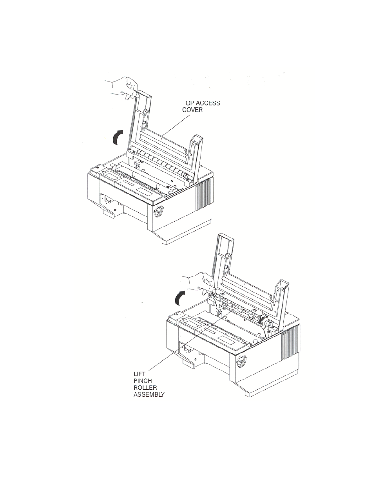
1.7 Install the Ribbon Cartridge
The following procedure is written for both initial installation and ribbon replacement.
1. Press the On/Off Line key to display "off line" status.
2. Open top access cover and lift roller assembly on models so equipped.
NOTE
If paper is loaded, press PARK key to park
the form in the tractors.
Page 30
User’s Guide
1-12
Figure 1-5: Open Access Cover (Both Options)
Page 31

User’s Guide
1-13
3. Check the Form Thickness Adjustment Knob to be sure that it is in the first position as
shown in Figure 1-6.
Figure 1-6: Form Thickness Adjustment Knob
NOTE
If replacing the ribbon, the Form Thickness
Adjustment Knob will automatically move
away from the form when the paper is parked
in the tractors.
Page 32

User’s Guide
1-14
4. Remove the ribbon guide from printhead (lift up and rotate towards front).
5. Remove ribbon cartridge from printer.
Figure 1-7: Remove Ribbon Guide
6. Move the printhead to the center of the printer.
NOTE
Steps 4 and 5 are not required for initial
ribbon installation.
Page 33

User’s Guide
1-15
7. Tighten ribbon.
8. Snap on ribbon guide.
9. Remove slack from ribbon.
Figure 1-8: Position Ribbon Cartridge In Printer
WARNING
PRINTHEAD GETS HOT DURING USE.
USE CAUTION WHEN HANDLING THE
PRINTHEAD.
Page 34

User’s Guide
1-16
10. Lower ribbon cartridge towards slots in printer. Ensure that ribbon loop is in front of
platen and that ribbon is not twisted.
11. Drop the ribbon cartridge into the ribbon alignment slots.
12. If the ribbon cartridge does not seat squarely on the ribbon drive, rotate the Ribbon
Advance Knob in the direction indicated by the arrow on the knob until the cartridge
drops into place on the ribbon drive. See Figure 1-9.
13. With ribbon guide tilted to front of printer, place the guide on printhead nose. Push
down on ribbon guide until it snaps into place.
14. Remove any slack from the ribbon by turning the Ribbon Advance Knob in the
direction of the arrow marked on the knob.
Page 35

User’s Guide
1-17
Figure 1-9: Install Ribbon Cartridge
Page 36

User’s Guide
1-18
1.8 Printer Self Test
This test is used to verify printer operation. Before performing the printer self-test, refer to
Section 3.3 Load Forms Page 3-3 for instructions on loading paper in the printer.
To start the test:
1. Load 8-1/2" forms.
2. Open the Keypad Door.
3. Press the Feature Key once. LCD will show "RUN SELF TEST".
4. Press the Enter Key. Printer self test will start (Figure 1-10). The display will
alternate between the following:
5. The self-test may be stopped by pressing the Enter key or by closing the Keypad
Door.
CAUTION
MARGINS ARE SET FOR 8.5” PAPER.
PRINTING OFF OF FORM WILL LEAD
TO PRINTER DAMAGE.
<Diagnostics>
‘Enter’ To Stop
Page 37

User’s Guide
1-19
Figure 1-10: Self-Test Sample
Page 38

User’s Guide
1-20
1.9 Interfacing
The three types of interfaces offered by the printer are RS-232 serial, RS-422 serial, and TTL
level 8-bit PC compatible, parallel interface. Serial and parallel interface connectors are
provided on the rear of the printer. The 25-pin serial connector is compatible for both RS-232
and RS-422.
Figure 1-11: Interface Connectors
Page 39

User’s Guide
1-21
Refer to the documentation for your computer to determine the type of shielded interface
cable needed and any unique pin-out configuration that may be required. This information
should be given to your dealer or distributor to determine the correct cable for your use.
Attach one end of the cable to the proper connector on the printer and the other end to the
host computer. Secure the interface cable to the connector with the screws or wire clips
provided.
WARNING
BEFORE CONNECTING THE CABLE,
MAKE CERTAIN BOTH THE HOST
COMPUTER AND THE PRINTER ARE
POWERED OFF.
Page 40

User’s Guide
1-22
1.10 RS-232 and RS-422 Serial Interface Configuration
1. Set the power switch to On.
2. Open the Keypad Door. The first menu will appear on the display.
3. Press the Next Menu key until you have accessed Menu 5
4. Press the Feature Key one time to select Baud Rate Feature.
5. Press the Value or Value to change baud rate to match host computer.
6. Press the Enter Key to save your selection.
7. Press the Feature key to select Serial RS-232.
8. Press the Value keys to select the desired serial mode [RS-232, RS-422, NONE].
Select NONE to disable the serial port.
9. Press the Enter key to save your selection.
10. Use the Feature , Value , and Enter keys to change any other required features in
this menu.
Parity
Data Bits
DTR
HANDSHK
X-ON CTRL ROBUST
X-OFF CTRL ROBUST
MODEM CTRL
11. Close the Keypad Door to exit Setup Mode. Display will alternate:
M1 PAGE FORMAT
M5 SERIAL CNTRL
Page 41

User’s Guide
1-23
12. Press the Profile key to permanently save the profile setting.
13. Press the On/Off Line Key to place the printer back on line.
Press ‘Profile’
To Save Settings
On Line Profile 1
Page 42

User’s Guide
1-24
Page 43

User’s Guide
2-1
2. Keypad Configuration
2.1 Keypad Configuration
This chapter describes the keypad, Ready LED, and LCD display. The locations of all keys
and their functions are illustrated below.
Figure 2-1: Keypad Configuration
Page 44

User’s Guide
2-2
2.2 Ready LED
The printer is equipped with one green LED indicator to signify READY status. Function of
the Ready indicator is as follows:
• On – Printer is on line and ready to accept data.
• Off – Printer cannot accept data for any of the following reasons:
a. Printer is off line.
b. Printer is in an error condition.
c. Printer FIFO is full.
d. Printer is powered off.
• Blinking – Printer is receiving data and printing. This light indicates the Ready/Busy
state of the interface.
Figure 2-2: Ready LED
Page 45

User’s Guide
2-3
2.3 On/Off Line Key Function
On/Off Line key functions are the functions printed on the Keypad Door encircling the
keypad. Primary key functions are used for normal operation. Setup Mode functions are
active when the Keypad Door is raised and are explained in Chapter 4.
Figure 2-3: Primary Keys
Page 46

User’s Guide
2-4
Pressing this key switches the printer between on line and off line status.
This key is used in conjunction with the LCD display. The On/Off Line key
is also used to continue after clearing an error condition or to acknowledge
tearing off a form on a paper path change.
Pressing this key will load paper into the main or alternate feed paths when
paper is not already loaded.
When continuous forms are loaded, pressing this key advances the paper to
the top of the next form.
When paper is loaded, pressing the Park/Path key ‘parks’ paper into the
tractors.
When paper is not loaded and the printer is off line, pressing the Park/Path
key changes the paper path and attempts to load paper (on dual path units).
Either Main or Alternate paper path can be selected using this key.
The Path key is only valid if the Path feature is set to “Either”. Paper paths
can also be selected by setting the path feature in a profile and selecting that
profile. For additional instructions, see 3.8 – 3.13.
Pressing this key moves the form upward 1/144 inch for precise form
alignment. When the key is pressed for more than ½ second, the paper
advances continuously until the key is released.
Page 47

User’s Guide
2-5
Pressing this key moves the form downward 1/144 inch for precise form
alignment. When the key is pressed for more than ½ second, the paper
reverse feeds continuously until the key is released.
Pressing this key advances forms up to the tear bar so that the last printed
form can easily be removed. Pressing the key a second time moves the form
back into print position.
To change the tear off position, press the Tear Off key, press Adjust or ,
and press the Tear Off key again. The new distance will be automatically
saved in the current profile.
Pressing this key once advances the paper by one line. When the key is
pressed for more than ½ second, continuous line feeds are performed until the
key is released.
This key allows you to select one of four user-defined profiles. To use this
key, place the printer off line; then press the Profile key. Available profile
names will be shown in the display window each time the Profile key is
pressed. This key can be used only when the printer is off line. For more
information about profiles see Chapter 4.
After changing profiles, the user should park and reload the paper to reset
top-of-form. The printer will automatically change paper paths or request a
form to be loaded depending on the Path feature setting. See Section 3.12 for
details on selecting paper paths using the Profile key.
Page 48

User’s Guide
2-6
2.4 LCD Display
The printer signals various messages through the LCD display. Examples are shown below:
Features and Values:
On Line Display:
Off Line Display:
Paper Out Conditions:
Initial Display when Keypad Door
is open:
Left Mar
g
in xxx
On Line Profile 1
Off Line Profile 1
<Paper Out Main>
<Paper Out Alt>
M1 PAGE FORMAT
Page 49

User’s Guide
3-1
3. Forms Handling
3.1 Recommended Types and Sizes
The following are guidelines for recommended paper types and sizes for use with the printer.
Continuous Forms (Main Paper Path)
Width – 3 ½ to 10 5/8 inches (88.9mm to 269.8 mm)
Individual Part Thickness - .005 inch maximum (.127mm)
Total Form Thickness - .028 inch maximum (.711mm)
Number of copies – 1 original plus 8 copies
Maximum Printable Width – 8.8 inches (223 mm)
NOTE
For small paper sizes, you need to remove the
rear paper supports.
Page 50

User’s Guide
3-2
3.2 Paper Paths
For best results, use the main paper path for thicker, stiffer forms.
Figure 3-1: Paper Feed Paths
Page 51

User’s Guide
3-3
3.3 Load Forms
To access the tractors and load a continuous form into either tractor, proceed as follows: (For
cut sheet forms, go directly to Step 8.)
1. Unlock both tractors by rotating the locking levers.
2. Align the left tractor with the alignment mark located on the body of the printer. Lock
left tractor in place. Place the right tractor at the approximate forms width.
NOTE
To load the main tractor path on Dual Path
printer, place alternate path tractors in
center position. Main tractor doors cannot be
opened with alternate tractors aligned in
front. (Hint: Use least frequently changed
paper in main tractors and frequently
changed paper or narrow stock in the
alternate path.) If both paths are used, main
tractor path must be loaded first.
NOTE
If paper is to be loaded into alternate path,
align the left tractors with alignment mark on
printer for both feed paths before loading
front most forms.
NOTE
Form Thickness Adjustment Knob
automatically retracts printhead to allow for
forms loading and repositions to print
position after loading.
Page 52

User’s Guide
3-4
3. Position the front paper guides and rear paper supports equally across width of form.
(Hint: For easy movement, grab the front paper guides and push up while sliding.)
4. Open the left tractor door and place the left side of the form in the left tractor. Close
tractor door. (Hint: Place form on lower 3 pins of tractor drive. Hold form in place by
pressing against tractor housing before closing tractor door with other hand.)
Figure 3-2: Load Paper In Tractors (Typical)
CAUTION
IMPROPER TRACTOR LOCATION
RESULTING IN PRINTING PAST THE
EDGE OF THE FORM CAN CAUSE
DAMAGE TO THE PRINTHEAD.
NOTE
Proper position of paper supports will help
prevent jams.
Page 53

User’s Guide
3-5
5. Open the right tractor door and load the paper into the right tractor. Compare position
of paper in left and right tractors and adjust as necessary to keep paper even. Improper
alignment of paper feed holes (Figure 3-3) will result in paper jam. Close tractor door.
6. If necessary, move the right tractor to the right to slightly tension the paper. Lock the
tractor in this position.
NOTE
For small paper sizes, you need to remove the
rear paper supports.
CAUTION
IMPROPER PAPER TENSION MAY
CAUSE PAPER JAMS. PAPER SHOULD
BE TENSIONED SUFFICIENTLY TO BE
RELATIVELY FLAT BETWEEN THE
TRACTORS, WHILE AVOIDING
DISTORTION OF THE PAPER FEED
HOLES.
Page 54

User’s Guide
3-6
Figure 3-3: Forms Loading (Sheet 1 of 2)
Page 55

User’s Guide
3-7
Figure 3-3: Forms Loading (Sheet 2 of 2)
Page 56

User’s Guide
3-8
7. Make sure the continuous forms are located directly under the tractors. The paper must
hang straight. Incorrect positioning of the forms may cause a paper jam.
Figure 3-4: Placement of Continuous Forms
Page 57

User’s Guide
3-9
8. Set the power switch to On. (For cut sheet forms, go directly to Step 10).
Figure 3-5: Turn On Power
9. After the printer initializes, press the Load key to load paper. When the load key is
pressed, the Form Thickness Adjustment knob will automatically move to the correct
location. Go to Step 11.
Figure 3-6: Press Load Key
Page 58

User’s Guide
3-10
10. Set left paper guide window at the “0” mark. Grab form in center with one hand and
align left edge of form against left paper guide. (Do not fully insert form.)
Use other hand to snug right paper guide against right edge of form. (Do not buckle
forms between paper guides.)
Push in form until leading edge is squarely against rollers. (Care should be taken to
keep form straight.) Printer will automatically load form and go on line.
Figure 3-7: Tear Off Bar Scale
NOTE
To eject a cut sheet form for any reason,
press the Form Feed Key.
Page 59

User’s Guide
3-11
11. Set form length, right and left margins. To set form length, first measure the length of
the form (in inches) and multiply this value by the vertical lines per inch. For
example: if the form length is 11 inches and the vertical pitch is 6 lines per inch, then
the form length would be:
11 inches x 6 lines per inch = form length 66 lines
To set the form length, open the keypad door and press the Quick Access key until
“Form Length” appears in the display. Press the Value keys to change the setting and
press the Enter key to save the setting.
To set left and right margins, measure the printed width of the form (in inches
excluding pinfeed holes) and multiply this value by the font pitch. The scale on the
tear off bar may be used to estimate margin location for 10 cpi.
For example: if the printed form width is 8.5 inches and the font pitch is 10 characters
per inch, then the form width would be:
8.5 inches by 10 cpi = right margin 85
To set the right margin, press the Quick Access key until “Right Margin” appears in
the display. Press the Value keys to change the margin setting and press the Enter keys
to save the setting. If you shift the left margin, you may want to shift the right margin
by the same amount. Close the keypad door to exit Setup Mode. The LCD will read:
12. Press Profile key to save settings.
13. Place the On/Off Line key to place the printer back on line.
Press Profile
To Save Settings
Page 60

User’s Guide
3-12
3.4 Top of Form Adjustment
(Adjusting First Printline Location)
When paper is loaded into the printer, the printer automatically positions the paper to print on
the first line of the form. If you need to change the location of the first print line, use the
Adjust Form key and proceed as follows:
1. To place the printer in Top-of-Form Adjust Mode, open the Keypad Door and press the
Adjust Form key. The form will advance until the bottom of the first print line is
positioned just above the tear off bar for viewing (Figure 3-9). (For units equipped
with cut sheet option, open the Top Access Cover and use the metal tear edge just
above the top rollers.)
2. Use the Value and Value keys to move the paper up or down to the position desired
for first line of type. The line directly above the tear bar will be the first print line
(Figure 3-9).
3. Press the Adjust Form key or close Keypad Door. The printer will reverse feed the
form back to print position.
4. This adjustment affects the Load feature and is automatically saved in memory for the
current profile and will apply the next time forms are loaded.
NOTE
Perform this adjustment immediately after
loading paper to determine where the first
line will print. Making this adjustment while
printing on the page allows fine alignment
without resetting line count.
Page 61

User’s Guide
3-13
Figure 3-9: Set First Print Line
Page 62

User’s Guide
3-14
3.5 Tear Off Adjustment
In a demand document application, the form will be advanced to a tear off position when the
Tear Off key is pressed. When the forms are in this position, the last printed form may be
removed by pulling the perforation against the tear edge of the cover.
If the perforation does not come to rest at the tear edge, the tear off distance may be adjusted
as follows:
1. Press the Tear Off key. The form should move up to the current tear location.
2. Using the Adjust key or the Adjust key, move the paper until the perforation is
located at the desired tear off position.
3. Press the Tear Off key. The form will return to the current print position.
4. This adjustment affects the Tear Distance feature and is automatically saved in
memory for the current profile and will be applied when forms are reloaded.
NOTE
By adjusting the tear distance to a large
value, the form can be fed through a
countertop, for example, if the printer is
located under a counter.
Page 63

User’s Guide
3-15
NOTE
For cut sheet units, to avoid excessive opening
and closing of the Top Exit Cover when
alternating between short cut sheet forms and
continuous tractor forms, adjust the tear bar
(metal edge located immediately above top
rollers) by using this procedure. (The value
will be about 1-40/144 inches.)
NOTE
The function of the Tear Off key is affected
by the Manual Tear feature located in the
Forms Control Menu. Refer to Chapter 4 for
a description of this feature.
Page 64

User’s Guide
3-16
Figure 3-10: Printer Located Under Countertop
Page 65

User’s Guide
3-17
3.6 Form Thickness Adjustment
The distance from the printhead to the paper is automatically changed to accommodate the
thickness of the forms whenever the unit is powered up or paper is loaded. The adjustment
can be manually changed using the knob on the right-hand side of the printer, or adjusted
automatically by changing the feature setting as outlined below:
1. Load the form requiring this adjustment and run a print sample.
2. Inspect the print sample. The characters should be easily read with no missing dots.
Be sure to check the last copy of multi-part forms for properly formed characters.
3. If the print quality is unacceptable (too tight, missing dots, or smearing), or paper
handling is affected, adjust form thickness gap as follows:
a. Open the Keypad Door to access Setup menu.
CAUTION
IMPROPER FORM THICKNESS
ADJUSTMENT CAN DAMAGE THE
PRINTHEAD.
NOTE
To adjust form thickness automatically and
store in memory, proceed with Step 3. If a
temporary adjustment is needed, adjust
manually beginning with Step 7.
Page 66

User’s Guide
3-18
b. Press the Next Menu key to access Menu 8, Form Thickness.
c. Press Feature key to obtain this display.
4. Use the Value keys to adjust the form thickness gap. Form thickness setting will be
stored in memory.
a. Press the Value key once or twice to reduce the form gap (moves the printhead
closer to the form) if there is light print.
b. Press the Value key once or twice to increase the form gap (moves the printhead
away from the form) if there is smudging, smearing or paper handling issues.
5. Once the adjustment has been made using the keypad, the printer will store the setting
in memory only in the selected profile. The printer will continue to use this gap setting
the next time forms are loaded.
M8 FORM THICKNESS
Adj Form Gap XX
NOTE
There is no direct correlation between form
thickness position and number of parts in a
multi-part form (e.g. adjustment control is
not set to the fourth mark for a four-part
form). Multi-part carbonless forms must be
given time to cure before being separated to
prevent light print quality. (Contact paper
supplier for cure times.)
Page 67

User’s Guide
3-19
6. Run another print sample. Return to Step 2 and repeat until print quality is acceptable.
7. Manually adjust the form thickness setting as follows (temporary adjustment, not
stored in memory):
a. Turn knob clockwise one click until print quality is acceptable.
b. If smudging occurs, thickness gap is too small. Turn knob one click
counterclockwise until print quality is acceptable.
Figure 3-11: Manually Move Form Thickness Adjustment Knob
Page 68

User’s Guide
3-20
3.7 Heavy Forms Adjustment
The Heavy Forms feature allows the printhead to be positioned horizontally on the form to
avoid labels, paper perforations or other variations in form thickness that can cause paper
handling issues.
This feature becomes active when the paper moves more than 0.5 inches.
The default location of the printhead is 2 inches from the left side of the printer.
To change the location of the printhead from the default value, follow these steps:
1. Load form in printer and open Keypad Door.
2. Press Menu key to access M2 Forms Control.
3. Press Feature key to access the Heavy Forms feature.
4. The value in the display represents the location of the printhead for form feeds and
paper advances over 0.5”.
5. Press the Value keys to change this setting.
For example: A label is located on the form from 3 to 5 inches from the left edge of the
form. Set the Heavy Form feature at 1.5 inches or 6.5 inches to insure that the
printhead and ribbon guide is away from the label during high speed paper moves. The
feature may also be set to avoid paper staples on the pin drive margins of the forms.
If the entire form is jamming, set this value to 9.8 inches to keep the printhead from the
perforation folds (paper tents) during form feeding.
Page 69

User’s Guide
3-21
3.8 Changing From Main Paper Path to Alternate Path
If continuous forms are presently loaded in the printer, you may change to the alternate paper
path by proceeding as follows:
(For cut sheet models, just insert the form. The following steps will be automatically
executed by the printer.)
1. Press the On/Off Line key to take printer off line.
2. Press the Tear Off key to advance the form to the tear off point.
3. Remove the last printed form.
4. Press the Park key. The continuous forms will be backed down out of the paper path
and held in the forms tractors. The display will appear as shown:
5. Press the Path key. The printer will shift to the alternate path then attempt to load
paper.
6. If paper is not loaded in the alternate path, the display will indicate so.
7. If paper is loaded, press On/Off Line key.
< Paper Out Main >
NOTE
To use the Path key, the ‘Path’ feature setting
must be set to ‘Either’ in the current selected
Profile. If the ‘Path’ feature is set to ‘Main’
or ‘Alt’, the Path key is disabled. See
Sections 3.12 – 3.13 for a description of paper
path changing using Profiles.
< Paper Out Alt >
Page 70

User’s Guide
3-22
Figure 3-12: Main and Alternate Paper Paths
(Cut Sheet not Shown)
Page 71

User’s Guide
3-23
3.9 Changing From Alternate Paper Path to Main
Paper Path
If paper is loaded in the alternate printer path, you may change to the Main Paper Path by
proceeding as follows:
1. Press the On/Off Line key to take printer off line.
2. Press the Tear Off key to advance form to tear off point. Remove last printed form.
3. Press the Park key. The continuous forms will be backed down out of the paper path
and held in the tractors. The display will appear as shown:
4. Press the Path key. The printer will shift to the Main Paper Path and automatically
load paper. If paper is not loaded in the main path, the display will indicate so.
5. If paper is loaded, press On/Off Line key.
<Paper Out: Alt>
<Paper Out: Main>
NOTE
To use the Path key, the ‘Path’ feature setting
must be set to ‘Either’ in the current selected
Profile. If the ‘Path’ feature is set to ‘Main’
or ‘Alt’, the Path key is disabled. See
Sections 3.12 – 3.13 for a description of paper
path changing using Profiles.
Page 72

User’s Guide
3-24
3.10 Paper Out Condition
When the printer runs out of paper, the following messages will appear in the display
depending on paper path selected:
or
1. Remove last printed form from paper path by using Form Feed key.
2. Load continuous forms. Refer to Page 3-3.
3. Press the On/Off Line key to go back on line.
The alternating display indicates which path (Main, Alt) is empty and which form to reload.
<Paper Out: Main>
<LOAD CHECKS>
<Paper Out: Alt>
<LOAD PROFILE 2>
NOTE
If the Profile has not been renamed to match
the form being used, the display will indicate
‘Load Profile x’ as shown in the example
above. In this case, the form associated with
Profile 2 should be loaded. For more
information on naming Profiles, see the
‘Rename’ feature located in the Profile
Control menu described in Chapter 4.
Page 73

User’s Guide
3-25
3.11 Automatically Changing Paper Paths On Paper Out
The printer may be configured to automatically change paper paths during a paper out
condition.
After changing paths, the printer will attempt a load. If paper is found, printing will continue.
If no paper is installed, the unit will stop and indicate a paper out condition.
To enable this feature:
1. Open Keypad Door.
2. Press the Next Menu key until Menu 4 is displayed.
3. Press Feature until feature is displayed.
4. Press Value to turn the feature on, and then press the Enter key to save selection.
5. Close Keypad Door and press the Profile key to save profile.
NOTE
This may be useful in applications where the
printer is unattended or installed at a remote
location. If this feature is enabled, the same
forms must be loaded in both paper paths.
M4 PRINTER CNTRL
Auto Path SW Off
Page 74

User’s Guide
3-26
3.12 Selecting Paper Paths Using the Profile Key
Each Profile contains a ‘Path’ feature which specifies the (Main, Alt, Either) paper path.
When a profile is selected, the paper path may be automatically changed or the operator may
be asked to load a new form in the currently selected paper path. The action taken depends
on the value of the ‘Path’ feature setting (located in Menu 2 Forms Control).
After using the Profile key to select a new profile, the operator should either press the On/Off
Line key or the Load key if paper is not loaded. The printer will then park the current form.
If the current form cannot be parked, the printer will advance the form to the tear bar and
display:
After tearing off the current form and pressing On/Off Line, the printer will then park that
form.
Example of profile names and paths:
Original Profile Name
New Profile Name Path
Profile 1 Checks Main
Profile 2 Invoice Alternate
Profile 3 Memos Alternate
Profile 4 Reports Alternate
< Tear Off Form >
< Press On/Off Line >
Page 75

User’s Guide
3-27
Example using same path:
The current profile is named “Invoices” and the paper path selected by that profile is
alternate. The new profile named “Memos” specifies the same path (Alt). After
selecting profile “Memos” and the printer has successfully parked the invoices, the
following message will be displayed:
After loading memos into the alternate path, press the Load key. The printer will load the
memos and resume normal operation.
Example using different path:
The current profile is named “Invoices” and the paper path selected by that profile is
alternate. The new profile named “Checks” specifies the main paper path. After
selecting profile “Checks” and the printer has successfully parked the invoices, the
printer will load the main paper path and resume operation. If there is no form
loaded in the selected path (main), the following message will be displayed:
After loading checks into the main paper path, press the Load key. The printer will load the
checks and resume normal operation.
< Load Memos in >
< Alt Paper Path >
< Paper Out: Main >
< Load Checks >
Page 76

User’s Guide
3-28
3.13 Selecting Paper Paths From the Host
Computer Using DPCL Command
In demand document applications, the paper path may be selected by using Downline Printer
Control Language (DPCL) sequences to select the active Profile 1-4. This command is
available in all emulation modes. Indicating a profile using DPCL commands will allow
paper path selection from the host computer. For more information on configuring features
and profiles, see Chapter 4.
After the profile is configured, it may be selected for the host computer using DPCL
sequences. The paper path will be selected according to the profile selection. Refer to
previous Section 3.12 for further information on paper path selection using profiles.
NOTE
In dual tractor units, the most frequently
used form should be loaded in the main path
and other forms in the alternate path. Now,
changing profiles will prompt the operator to
load the correct form in the alternate path.
To ensure the correct form is loaded, the
alternate path should be left empty when not
in use. This will cause the printer to stop and
indicate which form to load when the path is
selected.
Page 77

User’s Guide
3-29
The DPCL sequence to change profiles is active in all emulations.
Select Profile (form) <n> ESC$$E1.I18;<n>.X.
CODE FORMAT
ASCII: ESC $ $ E 1 . I 1 8 ; <n> . X .
DECIMAL: 27 36 36 69 49 46 73 49 56 59 n 46 88 46
HEXADECIMAL: 1B 24 24 45 31 2E 49 31 38 3B n 2E 58 2E
Description: This command is used to select Profile n where values of n range from 1 to 4.
The Paper Path may be selected by the Host Computer by configuring the
‘Path’ feature to Main, Alt, or Either, and by selecting the Profile using this
sequence.
Example: 10 rem select Profile 2
20 print chr$(27);”$$E1.I18;2.X.”
Comment: See Chapter 4 for a description of Profile features including the ‘Path’
feature.
* Only the Main selection is available on single path units.
Page 78

Page 79

User’s Guide
4-1
4. Features and Profiles
4.1 Features
This chapter describes and explains the various user programmable features of the printer.
Using the keypad, the printer can be easily configured to operate in a variety of host
environments and provide print for common applications such as reports, checks, invoices,
and labels.
The printer’s features are grouped into the following 10 categories:
Menu Name Feature Examples
M1 PAGE FORMAT Line/Inch, Form Length, Margins, etc.
M2 FORMS CONTROL Load Dst, Horz Adj., etc.
M3 PERSONALITY Emulations, Fonts, Character Sets, etc.
M4 PRINTER CONTROL Auto LF, Auto CR, etc.
M5 SERIAL CONTROL Baud Rate, Parity, Handshaking, etc.
M6 PARALLEL CONTROL Handshaking, Ack After Busy, etc.
M7 PROFILE CONTROL Naming, Saving Profiles, etc.
M8 FORM THICKNESS Auto Form Gap, Retract Printhead, adjust Form Gap, etc.
M9 DIAGNOSTICS Print Profile, Print Test, Firmware Rev., etc.
M10 SYSTEM CONTROL Off Line, Reset Key Lock, Quick Access, etc.
See Pages 4-11 through 4-26 for a detailed listing and description of all features and values.
NOTE
System Control Group must be activated for
access. See Appendix D.
Page 80

User’s Guide
4-2
4.2 Profiles
A unique benefit of this printer is its ability to store the feature settings for commonly used
applications in what is called a Profile. Up to four profiles may be named, stored in the
printer’s non-volatile memory, and recalled with a few key strokes. This avoids time
consuming setup and reprogramming each time the application changes.
Following is an example of some common forms used and specific features that may be
programmed into a profile when using these forms:
Profile Name/Feature Value
Feature Name
“Example”
P1
“Report”
P2
“Invoice”
P3
“Checks”
P4
“Statements”
Form Length 88 66 24 30
Lines/Inch 8 6 6 6
Right Margin 136 80 70 70
Horz Adj 135/144 135/144 100/144 200/144
Manual Tear FF TOF TOF TOF
Emulate IBM PRO IBM PRO LA 120 LA 120
Font DP 17.1 Draft 10 OCR A Draft 10
Parallel Enable Disable Disable Enable
Path Main Either Alternate Alternate
Page 81

User’s Guide
4-3
In this sample, change from printing “Reports” to “Checks” as follows:
1. Take printer off line by pressing the On/Off Line key.
2. Park current form.
3. Change to desired profile, in this case “checks”.
4. Load the appropriate forms (“checks”).
5. Place unit on line.
For an application that is not stored in a profile, call up the profile whose features most
closely match the application and reprogram only the features requiring change. These
changes will not alter the profile’s permanent settings unless you save them when you exit
Setup Mode.
Page 82

User’s Guide
4-4
4.3 Setup Mode Key Functions
To change features, open the Keypad Door to enter Setup Mode. Figure 4-1 shows the Setup
Mode keys and their respective functions.
A brief description of each key function follows:
Figure 4-1: Setup Mode Keys
Page 83

User’s Guide
4-5
The Value keys are used to change the value of a feature. Pressing the
Value key increases feature values. Pressing the Value ke
y
decreases
feature values.
The Next Menu key provides access to a specific group of features. Pressin
g
this key steps through the printer features by menu. This prevents having to
“c
y
cle through” the entire list using the Feature key in order to get to the
desired feature.
This key provides immediate access to typical features required for quic
k
setup. These include font, margins, form length, and lines/inch. The features
accessed by this key can be changed to correspond to the user’s needs.
The Feature keys are used to select a specific feature. Press the Feature ke
y
will move the display up the features list. Pressing the Feature key will
move the displa
y
down the features list. When a menu boundary is crosse
d
in either direction, it will be displayed.
The Enter key is used to accept new values for printer features. After the
value of a feature has been changed, the Enter ke
y
is pressed to save the new
settings into memory.
This key enables the user to adjust the top-of-form setting (first printline
location) using the Value keys.
Page 84

User’s Guide
4-6
4.4 LCD Display
In Setup Mode, the LCD display provides the following information:
Feature Name and Value:
Menu Names:
Diagnostic Tests:
Form Length 88
M1 PAGE FORMAT
Self Test
Page 85

User’s Guide
4-7
4.5 Profile Feature Listing
To print a listing of the feature settings of a particular profile, follow the steps below:
1. Make certain 20 column or wider paper is loaded in the printer.
2. Press the On/Off Line key to take the printer off line.
3. Before entering Setup Mode, press the Profile key until it displays the profile you wish
to print.
4. Open the Keypad Door and use the Next Menu key to go to Menu 9. The display will
read:
5. Press the Feature key until display reads:
6. Press the Enter key. The printer will print a listing of the profile feature settings.
7. Close the Keypad Door to exit Setup Mode after printout is complete.
8. Press the On/Off Line key to return to normal operation.
M9 DIAGNOSTICS
Print Profile
Page 86

User’s Guide
4-8
4.6 Changing Features in a Profile
Feature settings in a profile may be changed through the keypad by following the steps
below:
1. Press the On/Off Line key to take the printer off line.
2. Press Park key to park paper.
3. Press the Profile key to select profile being changed.
4. Open the Keypad Door.
5. Press the Next Menu key, as necessary, to scroll through the feature menus until you
reach the menu containing the feature you wish to change.
6. Press the Feature or the Feature key to scroll the display up or down until you reach
the feature to be changed.
7. Press the Value key or the Value key to scroll the display backward or forward until
you reach the value you wish to set.
Figure 4-2: Changing Features in a Profile
8. Press the Enter key to record the new value.
Page 87

User’s Guide
4-9
9. Repeat Steps 5 through 8 as necessary until all features are correctly set for your
application.
10. Close the Keypad Door to exit Setup Mode. The alternating display will read:
To answer “Yes”, press the Profile key. This will permanently record the change in
non-volatile memory for that profile.
To answer “No”, press any other key. This will make the change temporary, thus not
changing the original profile setting. These settings will be valid until profiles are
changed again or the printer is powered off.
11. Press Load key to load paper (resets top-of-form).
12. Press the On/Off Line key to return to operation.
Press ‘Profile’
To Save Settings
NOTE
To maintain correct top-of-form alignment
when a profile change is made, the paper
should be parked (if not already parked) and
reloaded so that the printer can reset the topof-form for the new profile.
Page 88

User’s Guide
4-10
As an example, assume the profile you are presently using defines the lines per inch as 6. To
permanently change the lines per inch to 8, proceed as follows:
1. Press the On/Off Line key to take the printer off line.
2. Press Park key to park paper.
3. Open the Keypad Door to enter Setup Mode.
4. Press the Feature key to select Lines/Inch.
5. Press the Value key to change the Lines/Inch to 8 lines.
6. Press the Enter key to save the new Lines/Inch value.
7. Close the Keypad Door to exit Setup Mode. The LCD will read:
Press Profile key to save entry.
8. Press the Load key to load paper (resets top-of-form).
9. Press the On/Off Line key to place the printer back on line.
After pressing the On/Off Line key, the printer will operate with the vertical motion defined
as 8 lines per inch. The next time this profile is selected, or if the printer power is switched
off and back on, the lines per inch margin will remain at 8 lines per inch.
Press ‘Profile’
To Save Settings
Page 89

User’s Guide
4-11
4.7 User Programmable Features
Menu 1: Page Format
Printer Displays Values Description
Lines/Inch ### 1
2
3
4
6
8
12
Vertical pitch for printing text in lines per inch.
Form Length ### 1
.
.
200
Lines per page resets top and bottom margins.
Value cannot exceed bottom margin.
Top Margin ### 1
.
.
.
200
Number of lines from the top-of-form and the
first print line.
Value cannot exceed form length.
Bottom Margin ### 1
.
.
.
200
Bottom margin
The last print line allowed on the form
Value cannot exceed form length.
Left Margin ### 1
.
.
MLL
The left margin can be set from 1 to the right
margin.
Maximum Line Length (See Appendix A)
Right Margin ### LM
.
.
MLL
Clear Horizontal Tabs
Pressing the Enter key will clear all horizontal
tabs.
Maximum Line Length (See Appendix A)
Page 90

User’s Guide
4-12
Menu 1: Page Format (Cont’d)
Printer Displays Values Description
Clear Horz Tabs
Clear Horizontal Tabs
Pressing the Enter key will clear all horizontal
tabs.
Horz Tab ### xxx Set/Clr Horizontal Tabs
Pressing the Value key selects the column (#)
where a horizontal tab may be set or
cleared.
Pressing the Enter key will Set or Clr (clear) a
tab in that column
Clear Vert Tabs
Clear Vertical Tabs
Pressing the Enter key will clear all horizontal
tabs.
Vert Tab ### xxx Set/Clr Vertical Tabs
Pressing the Value key selects the line (##)
where a vertical tab may be set or cleared.
Pressing the Enter key will Set or Clr (clear) a
tab in that line.
4-8
Page 91

User’s Guide
4-13
Menu 2: Forms Control
Printer Displays Values Description
Load ###/144”
0 0/144
.
.
.
.
.
Current
Form
Length
In Inches
This feature is used to align the first printline
of a form and the printhead. This feature is
normally set using the Adjust Form key.
This feature is active only during paper
loading.
Increments are in inches or 1/144
th
of an inch.
This feature determines if the print head moves
during a Load function. This feature is only
used during paper loading.
On The print head will move while the paper is
being loaded. This normally will prevent
fanning of a multi-part form.
Load Crg Mov ###
Off The print head will stay to the far right of the
carriage. No motion will occur until the
printer seeks the thickness of the form.
Horz Adj xxx/144” 0/144
.
.
.
144/144
This feature allows the user to logically offset
the form horizontally to the left, up to 1
inch. This feature is active immediately
when set.
Tear x xxx/144” 0 0/144
.
.
.
11 0/144
This feature determines the distance the paper
is moved when the Tear Off key is pressed.
Page 92

User’s Guide
4-14
Menu 2: Forms Control (Cont’d)
Printer Displays Values Description
Manual Tear xxx FF The printer will perform a form feed before
moving to the tear position after pressing
the Tear Off key.
TOF The printer will move to the tear position after
printing crosses the next forms boundary
after pressing the Tear Off key.
No FF This value will move the paper the tear
distance only. No form feeds are
performed.
Manual Time ###s OFF The Tear Off key must be pressed to return the
forms to the print position.
1
.
.
30
The time in seconds that the form will be in the
tear position before automatically returning
to the print position.
This feature works only with the Manual Tear
key.
Auto Tear xxx OFF Values set for “Off”, the printer will not move
the form into the tear position if the form is
at top and no data is being transmitted.
IDLE
Value set for “Idle”, the printer will move the
form into the tear position if the form is at
top and no data is being transmitted.
PAGE Moves the form to the tear bar position on
every page break while on line. The form
will retract after the time specified by the
“Auto Time X” feature has expired.
Page 93

User’s Guide
4-15
Menu 2: Forms Control (Cont’d)
Printer Displays Values Description
Auto Time ###s 1
.
.
.
.
.
.
30
The time in seconds that the form will be in the
tear position after more data is sent to the
printer.
This feature works only when the Auto Tear
feature is ON.
HF: Pos crg x.x” 0.0”
0.1”
0.2”
.
.
.
9.8”
Specifies the position of the carriage, when the
Heavy Forms feature is enabled. The
maximum value is dependent on the current
value of the Horz Adj xxx/144” feature.
HF: xxxxxxxxxxxx
On Feed
> x.x”
0.0”
0.1”
0.2”
.
5.0”
On page
break
Disabled
Specifies when the Heavy Forms sequence is
initiated.
On a paper feed greater than x.x inches the
carriage is positioned to the location
specified by the HF:Pos crg x.x” feature.
The default = .5” which is 3 lines @6 LPI.
On a form feed (FF) or paper move that
crosses a forms boundary or bottom margin
(page break), the carriage will be positioned
to the location specified by the HF: Pos crg
x.x” feature.
Heavy forms sequence is disabled.
Page 94

User’s Guide
4-16
Menu 2: Forms Control (Cont’d)
Printer Displays Values Description
Path xxxxx Either
Main
Alt.
Allows the current profile to be paper path
specific.
Paper Speed ### 3
.
.
.
.
15
This feature controls the paper feed speed in
inches per second.
Slower speeds may improve paper handling of
certain forms.
Page 95

User’s Guide
4-17
Menu 3: Personality
Printer Displays Values Description
Emulate xxxxxxxx IBM Pro
IBM Grph.
LA 120
Epson FX
DS-180
Display
This feature selects the desired emulation.
Escape sequences for each emulation are listed
in the “Programmer’s Manual.”
Hex display feature, see “Troubleshooting and
Maintenance” for further information.
Font xxxxxxxxxx DP 10
DP 12
DP 13.2
DP 15
DP 16
DP 16.5
DP 17.16
DP 18
DP 20
Data processing fonts.
Italic print quality will vary when using DP
fonts.
Draft 10
Draft 12
Draft 13.2
Draft 15
Draft 16
Draft 16.5
Draft 17.16
Draft 18
Draft 20
Draft fonts (9 x 12 matrix)
Courier 10
Prestige 12
OCR_A 10
OCR_B 10
NLQ font (18 x 24 10 cpi)
NLQ font (18 x 20 12 cpi)
NLQ font (18 x 36 10 cpi)
NLQ font (18 x 36 10 cpi)
Page 96

User’s Guide
4-18
Menu 3: Personality (Cont’d)
Printer Displays Values Description
Set xxxxxxxxx 7 Bit ASCII
DEC Supplmt1
IBM Code 437
IBM Code 850
Epson Italic
Epson Graph
Epson Ital/Gr
Refer to “Programmer’s Manual” for
character tables.
Nat. xxxxxxxx USA
UK
France
Germany
Italy
Switzerland
Canadian Fr
Japan
Latin Am
Spain
Denmark
Norway
Finland
Sweden
Spain II
Denmark II
Sp/Lat Am
Nor/Den
Swed/Fin
All nationalities are available in all symbol
sets, fonts, and emulations (except OCR A
and B) using Setup Mode. The actual
nationality selected using emulation escape
sequences vary depending on emulation.
Refer to the Programmer’s Manual for
each emulation.
IBM CHAR Set 1 or 2
Print Zero as #
0
Ø
Prints Zero without a slash
Prints Zero with a slash
Page 97

User’s Guide
4-19
Menu 4: Printer Control
Printer Displays Values Description
Auto LF xxx Disable
Enable
No line feed with carriage return.
Performs a line feed with carriage return.
Auto CR xxx Disable
Enable
No carriage return with line feed.
Performs a carriage return with line feed.
Wrap xxx
Disable
Enable
Printable data past the right margin is ignored.
Performs a carriage return line feed if data
exceeds the right margin.
Print xxxxxxxx
Bidirect
Unidirect
Bi-Directional printing
Unidirectional printing prints left-to-right only.
Auto Path SW xx ON
OFF
When this feature is set to ‘ON’ and a paper
out occurs while printing, the printer will
automatically change to the other paper
path and continue printing if the forms are
loaded successfully.
This feature is valid only on dual tractor units.
Vert Graphic xxx ON
OFF
Specifies status of the TI-885 raster graphics
mode
When ON Anadex graphics is enabled when
DS-180 Emulation is selected.
Horz Graphic xxx ON
OFF
Specifies status of the TI-885 horizontal
graphic mode
Power Up xxxxxxxx On Line
Off Line
Specifies whether printer powers up into on
line or off line status
Page 98

User’s Guide
4-20
Menu 4: Printer Control (Cont’d)
Printer Displays Values Description
Buffer Size xxxx 512
.
.
.
.
.
Max
Specifies the size of the data buffer.
Lower limit of this range may be limited by
“Window Size” feature.
Depends on buffer option installed
Window Size xxxx 256
.
.
.
.
.
.
Max
Size Less
1024
Window (FIFO size)
Specifies how many bytes of data must be
emptied out of a full data buffer before the
communication interface will go into the
“Ready” mode
Upper limit of this range is limited by the
“Buffer Size” feature.
Ribbon ##% Used This feature displays the estimated ribbon
used. The value is based upon the
percentage of Max Ribbon feature.
Dble Strike xxx ON
OFF
Prints in unidirectional emphasized mode.
Used for higher contrast on multi-part
forms
Normal print.
Page 99

User’s Guide
4-21
Menu 4: Printer Control (Cont’d)
Printer Displays Values Description
DGCL xxxxxxx Disable
Enable
Disables recognition of Barcode Transparency
commands
Enable recognition of Barcode Transparency
Commands
Exit Mode xxxxxx Adjust
Return
No Adj
BC-300
Adjust the form to the next logical line feed
boundary upon exiting the Barcode Task
mode.
Return the form to the last active vertical
position upon exiting the Barcode Task
mode. See the ^J000 command
Position the form directly below the last
printable pass of the Task mode upon
exiting the Task mode
Emulates the Barcode 300 exit mode.
Command Char xxx 33
255
Defines the default command character
Example: 94 represents the [^] character
Overlap xxxxxxx Disable
Enable
Disables one dot overlap when printing
barcodes
Enables one dot overlap when printing
barcodes
DW Term Disable
Enable
Double wide print is not affected by line
terminations
Double wide print is cancelled by CR, LF, FF,
and VT
Valid only when DS-180 Emulation is
selected.
See Chapter 6 in Programmer’s Manual for barcode programming.
Page 100

User’s Guide
4-22
Menu 5: Serial Control
Printer Displays Values Description
Baud Rate xxxx 110
300
600
1200
1800
2400
4800
9600
19.2k
Refer to the documentation of your host
computer to determine the baud rate.
Serial xxxxx RS-232
RS-422
OFF
Selects serial configuration
Cable must be configured to match. See
Appendix B
Selecting OFF disables both serial
configurations.
Parity xxxxx None
Even
Odd
Space
Mark
Refer to the documentation for your host
computer to determine parity.
Space 8
th
Bit only
Mark 8
th
Bit only
Data Bits xxxxxxx 7
8
Refer to the documentation for your host
computer to determine data bits.
 Loading...