

Page 1
Brady Wand
RF/ID Reader
Users Guide
Preliminary
RFID Systems
1
Page 2

RFID Systems
Contents
Important Information ................................................................Page 2
Specifications .............................................................................Page 3
Introduction ................................................................................Page 4
Setup and Wiring ................................................................Page 6
Wand Operation .......................................................................Page 12
Troubleshooting .......................................................................Page 13
Brady Wand Users Guide Copy write 1998,WH Brady
2000-0001
2
Page 3

RFID Systems
Important Information
Limited Hardware Warranty
Brady USA, Inc. warrants solely to the purchaser that the hardware components of the Wand
RFID reader will be free from defects in materials and workmanship under normal use for a
period of 90 days from the date of shipment by Brady USA. This limited warranty does not
extend to any components which have been subject to misuse, neglect, accident, or improper
installation or application. Brady USA’s liability and the purchaser’s remedy for the breach of
this warranty shall be at Brady USA’s option to either (i) repair or replace defective components
or (ii) upon return of the defective components, refund the purchase price paid for the
components. EXCEPT FOR THE LIMITED HARDWARE WARRANTY SET FORTH ABOVE,
BRADY USA AND ITS LICENSORS PROVIDE THE HARDWARE ON AN “AS IS” BASIS, AND
WITHOUT WARRANTY OF ANY KIND EITHER EXPRESS, IMPLIED OR STATUTORY.
Limitation of Liability
In no event shall Brady USA or its suppliers be liable for any damages in excess of the price paid
by you to Brady USA for the component, regardless of under what legal theory such damages
may be alleged arising out of the use or inability to use the component, even if
Brady USA has been advised of the possibility of such damages.
FCC
This device complies with Part 15 of the FCC Rules. Operation is subject to the following
conditions: (1) this device may not cause harmful interference, and (2) this device must accept
any interference received, including interference that may cause undesired operation.
FCC ID
NUC -BW125IS
Brady Wand Users Guide Copy write 1998,WH Brady
2000-0001
3
Page 4

RFID Systems
Specifications
Input Voltage...........................................................5 or +12V D/C Nominal
Input Current
While Activated.................................................150 mA
Standby ..............................................................20 mA
Tag Protocols Supported..........................................Phillips, Hitag,
Frequency of Operation...........................................125 kHz
Modulation ..............................................................ASK (Amplitude Shift Keying)
Dimensions ..............................................................11.00” L x 1.75” W x .875” H
(27.94 cm L x 4.45 cm W x 2.22 cm H)
Weight.....................................................................1lb(.453 kg)
Temperature
Operating.............................................................-4 º to + 104 º F (-20 º to +40 º C)
Storage.................................................................-40 º to + 140 º F (-40 º to +60 º C)
Data output Formats
RS-232/422/485................................................... 9600 baud, 1 stop, 8 data, carriage return
Barcode Emulation...............................................Code 39
Typical Tag Read Time
40 Bit...................................................................20m sec
256 Bit................................................................40m sec
1056 Bit..............................................................100m sec
2048 Bit..............................................................500m sec
Brady Wand Users Guide Copy write 1998,WH Brady
2000-0001
4
Page 5

RFID Systems
Introduction
Brady RF/ID systems consist of Brady RF/ID tags and a reader/writer for reading data from tags
or writing data to tags. Several different types tags and various reader options are available to
suite any application.
Brady RF/ID Tags
Brady RF/ID tags consist of a microchip, coil antenna, and packaging. Packaging and microchip
options can be combined to fit any RF/ID tag requirement.
Microchip options include read only, read write and several different memory capacities for
read/write applications. Typically, read only tags are randomly preprogrammed with 40 bits(10
HEX Characters) of permanent data. Versions of read only tags are available which can be
programmed once with a designated number. This number is then permanently stored in the tag
and can be read many times. This type of tag is typically referred to as a WORM (write once read
many).
Read/write tags have permanent data as well as programmable data. The permanent data is
similar to a read only tag. It is usually 32 bits (8 HEX Characters) of data which can not be
changed. Read/write tags also have memory which can be changed. The amount of changeable
memory in a read/write tag ranges from 152 bits (19 Alphanumeric Characters) to 1536 bits (192
Alphanumeric Characters). Versions of read/write tags are also available with password
protection or data encryption for high security applications that require secure data transmission
between the reader and the tag.
Packaging options include a variety of forms as well as different case materials for a wide range
of operating temperatures and chemical resistance.
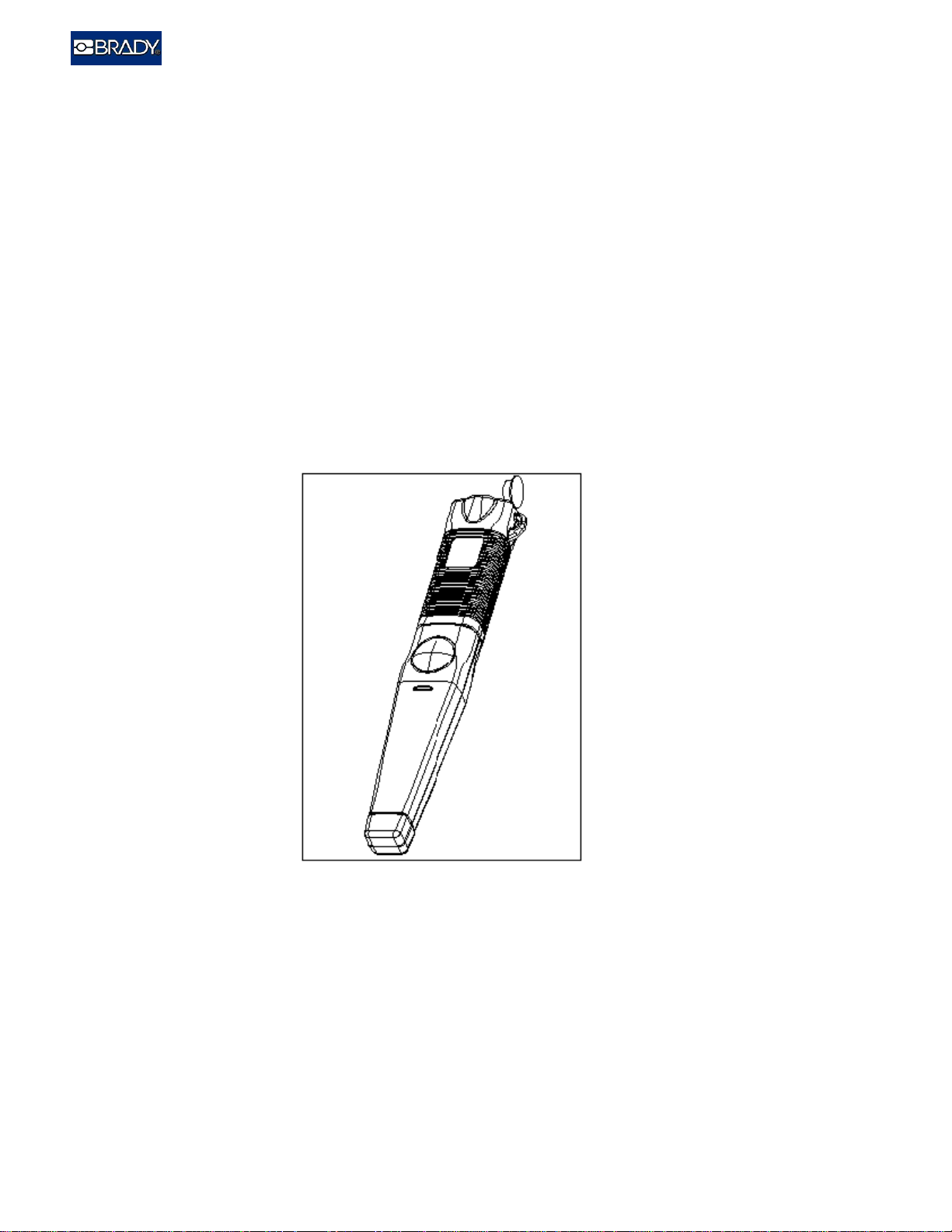
Brady Wand
The Brady Wand is an RF/ID reader which interfaces to a host PC or hand held data collection
device through standard RS-232/422/485 or Wand emulation hardware format. The reader is
typically powered from the host device with 5V D/C. If an un-powered data port is used, an
external battery source must be provided to power the reader.
The Brady Wand was designed to be used in various Industrial applications which require rugged
and reliable equipment. Versions of the Wand are available with an Intrinsically Safe Rating
which allow them to be used in explosion hazard areas. The Wand is water resistant and can
withstand many of the harsh chemicals found in industrial manufacturing and petrochemical
processing. In environments where visual and audible indicators can not be heard or seen, the
Brady Wand has a unique vibrating feature for indicating reader status to the operator.
Brady Wand Users Guide Copy write 1998,WH Brady
2000-0001
5
Page 6
RFID Systems
Use
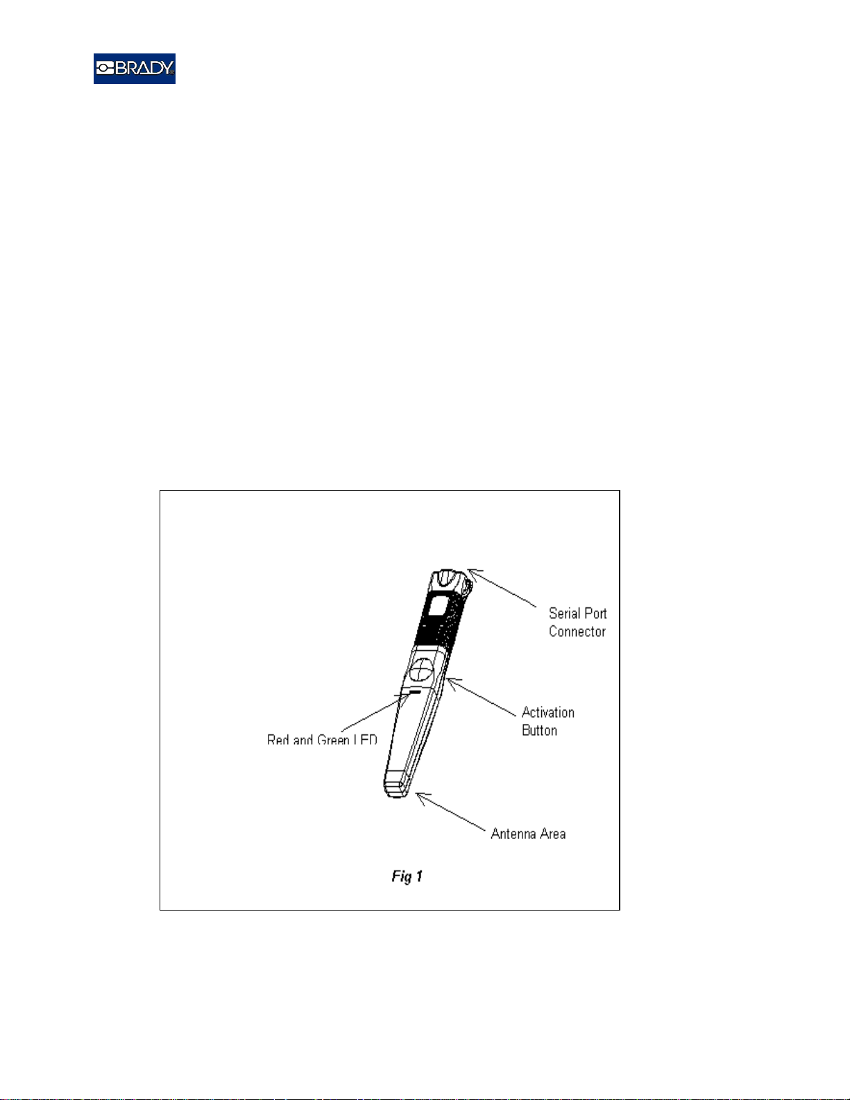
Operating the Brady Wand is very easy. To read/write to a tag the operator presses the large
activation button located above the hand grip.(see fig.1). Once the button is pressed, the reader
electronics sends out a radio frequency field to search for a tag. During this time the red LED,
located above the button, will illuminate indicating that the Wand is in search mode. When a tag
is present within the field of the reader antenna, the microchip inside the tag is activated and
transmits its ID code back to the reader. . If the data received from a tag is valid, the green LED
located above the activation button will illuminate, an audible “beep” will sound, and the wand
will vibrate for a short period of time.
After the reader receives the transmission from the tag, it converts this information RS232/422/485 or Wand emulation format and transmits the data to the host.
The Brady Wand can also be used remotely without pressing the button. When used for remote
read/write operation, commands which activate the reader/writer are sent from the host to the
Wand without the need for pressing a button. (See Programmers Guide for information on host
commands).
Brady Wand Users Guide Copy write 1998,WH Brady
2000-0001
6
Page 7

RFID Systems
.
Brady Wand Users Guide Copy write 1998,WH Brady
2000-0001
7
Page 8

RFID Systems
Setup and Wiring
The following is a simple procedure for setting up and operating the Brady Wand RF/ID
read/writer. Follow the instructions carefully. Any deviation from these instructions may void the
Limited Hardware Warranty.
Upon Receipt
Remove items from shipping the container.
Check package contents for the following items:
1. Brady Wand Reader/Writer
2. Coil cable with circular connector and flying leads.
3. Optional accessories.
Fill out and return product registration card.
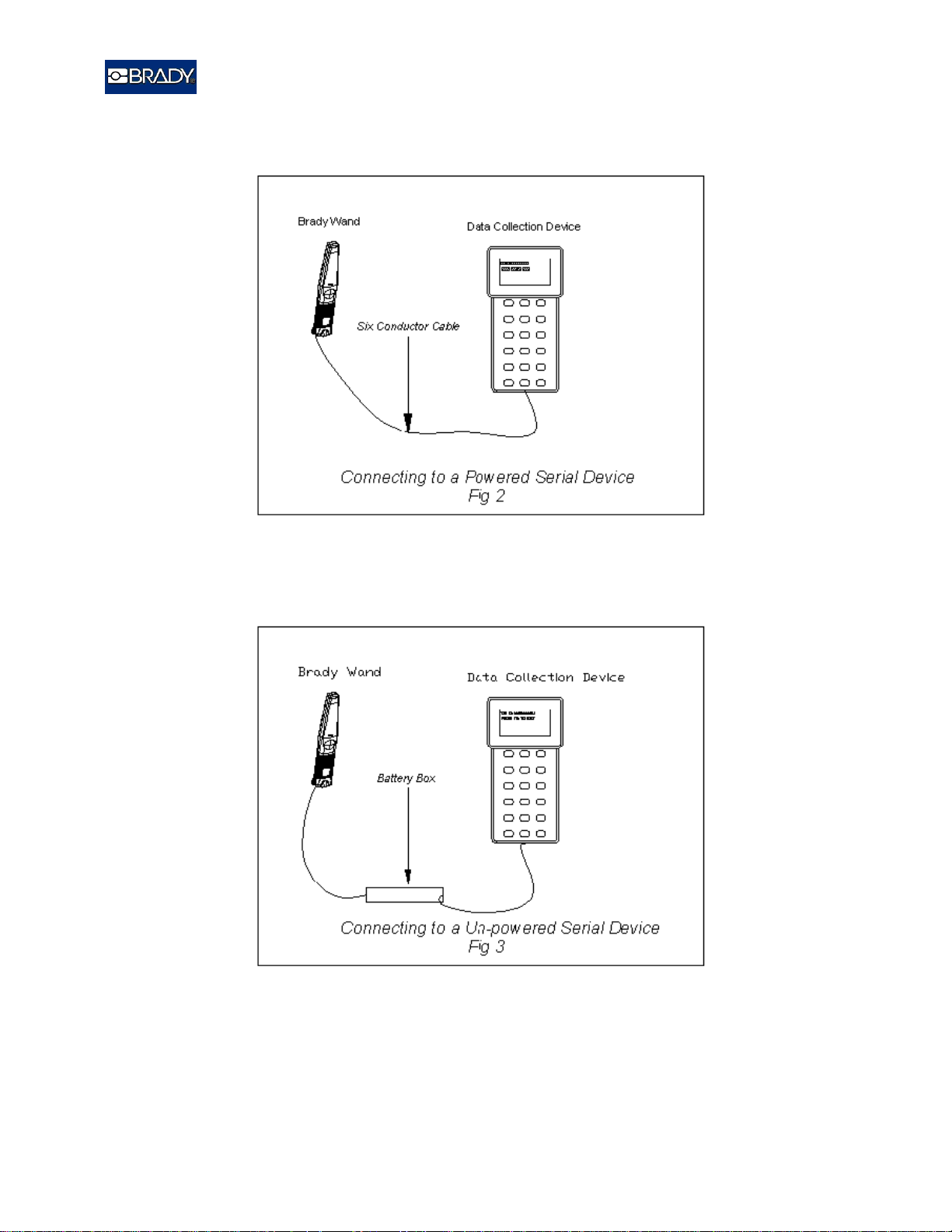
Connecting the Brady Wand to a Data Collection D e vice
The coil cable is used for connecting the Brady Wand reader/writer to a host computer or data
collection device. (See Fig 2 and 3 page 7 ) Because of the many different data collection devices
and serial port formats which can be used, consult the owners manual of the data collection
device to be used for proper wiring and connector information. See wiring diagrams on page
8,9,10,11 for detailed wiring and connector pin-out information about the Brady Wand.
Once you have determined the proper wiring and connector information for the data collection
device, the cable can be plugged into the Brady Wand.
*Connectors are available at the time of purchase to match to most common data collection
devices.
If you are interfacing to a data collection device which does not provide power through the serial
port, you must use the optional external power interface box. This box is connected between the
data collection device’s serial port and the Brady Wand’s serial port. The external power
interface box provides battery power from one 9V battery. (See fig 3 page 7).
Brady Wand Users Guide Copy write 1998,WH Brady
2000-0001
8
Page 9
RFID Systems
Brady Wand Users Guide Copy write 1998,WH Brady
2000-0001
9
Page 10

RFID Systems
t
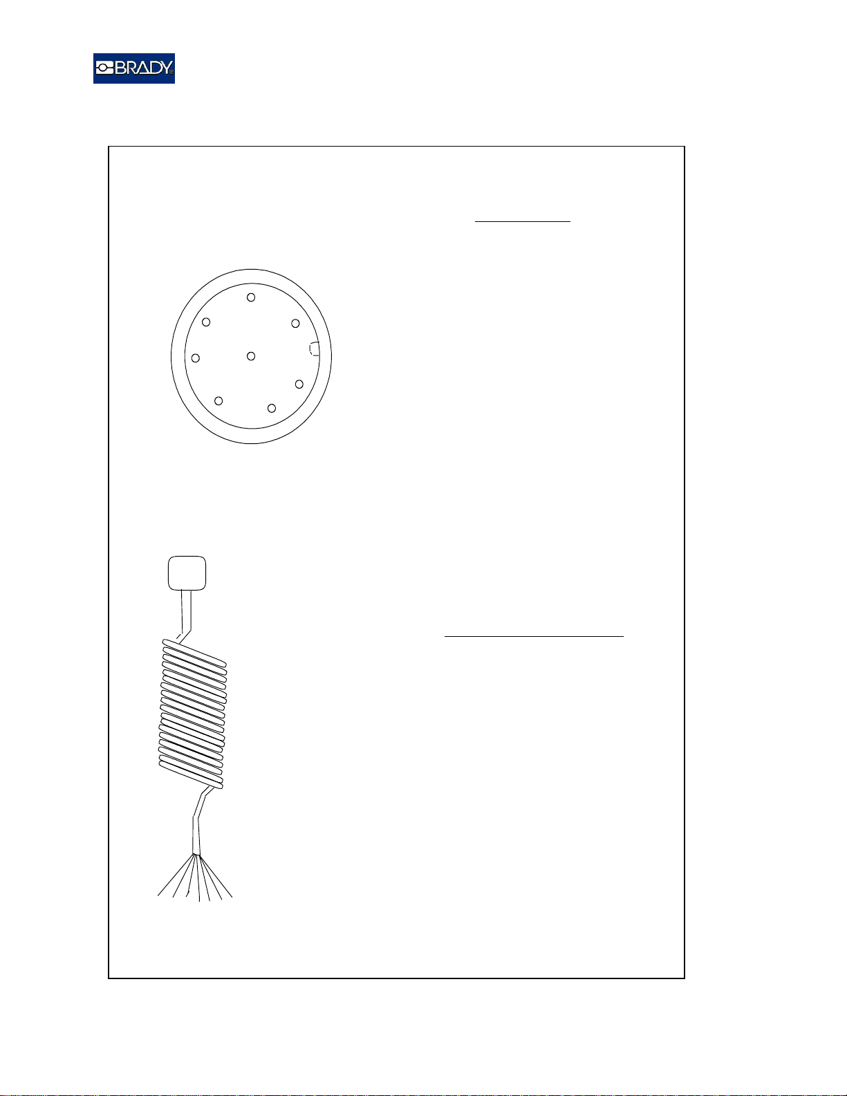
RS-232
2
8
7
6
Connector on Wand
Veiwed From Bottom Of Wand
3
1
4
5
Pin Assignment
+5-12V D/C+5-12V D/C
+5-12V D/C
1
RX Data
2
TX Data
3
N/C
4
GND
5
N/C
6
N/C
7
N/C
8
**
RX Data from the Wand needs to
be connected to TX Data from Hos
*
TX Data from tw Wand needs to be
connected to RX Data from the Host
**
*
Circular Connector
On Cable Assembly
8 Flying
Leads
Fig 4
Flying Leads
Cable Conductor Assi gn m e n t
Red
Green
White
Orange
Black
Brown
Yellow
Violet
+5-12V D/C
RX Data
TX Data
N/C
GND
N/C
N/C
N/C
Brady Wand Users Guide Copy write 1998,WH Brady
2000-0001
10
Page 11

RFID Systems
Brady Wand Users Guide Copy write 1998,WH Brady
2000-0001
11
Page 12

RFID Systems
RS-422
2
8
7
6
Connector on Wand
Veiwed From Bottom Of Wand
3
1
4
5
Pin Assignment
+5-12V D/C+5-12V D/C
+5-12V D/C
1
RXA
2
TXA
3
N/C
4
GND
5
6
RXB
TXB
7
N/C
8
Circular Connector
On Cable Assemb ly
8 Flying
Leads
Fig 5
Flying Leads
Cable Conductor Assignment
Red
Green
White
Orange
Black
Brown
Yellow
Violet
+5-12V D/C
RXA
TXA
N/C
GND
RXB
TXB
N/C
Brady Wand Users Guide Copy write 1998,WH Brady
12
2000-0001
Page 13

RFID Systems
RS-422
2
8
7
6
Connector on Wand
Veiwed From Bottom Of Wand
3
1
4
5
Pin Assignment
+5-12V D/C+5-12V D/C
+5-12V D/C
1
RXA
2
TXA
3
N/C
4
GND
5
6
RXB
TXB
7
N/C
8
Circular Connector
On Cable Assemb ly
8 Flying
Leads
Fig 6
Flying Leads
Cable Conductor Assignment
Red
Green
White
Orange
Black
Brown
Yellow
Violet
+5-12V D/C
RXA
TXA
N/C
GND
RXB
TXB
N/C
Brady Wand Users Guide Copy write 1998,WH Brady
13
2000-0001
Page 14
RFID Systems
BAR CODE Emulation
(Read O nly )
2
8
7
6
Connector on Wand
Veiwed From Bottom Of Wand
3
1
4
5
Circular Connector
On Cable Assemb ly
Pin Assignment
+5-12V D/C+5-12V D/C
+5-12V D/C
1
N/C
2
N/C
3
N/C
4
GND
5
6
N/C
N/C
7
8
Cable Conductor Assignment
TX D a ta
Flying Leads
Red
Green
White
Orange
Black
Brown
Yellow
Violet
8 Flying
Leads
+5-12V D/C
N/C
N/C
N/C
GND
N/C
N/C
TX D a ta
Fig 7
Brady Wand Users Guide Copy write 1998,WH Brady
2000-0001
14
Page 15

RFID Systems
Brady Wand Users Guide Copy write 1998,WH Brady
2000-0001
15
Page 16

RFID Systems
Wand Operation
Operating Hints
Because the Brady RF/ID System uses radio frequency (RF) energy to communicate between the
tag and the Wand, there are several important points to keep in mind while setting up and
operating the system.
Metal effects both Wand and tag antennas by reducing the read range of the overall system. If
at all possible, keep tags and the Wand antenna away from metal.
Interference from other electronic sources can reduce read range. If the interference is strong
enough, it may render the system inoperative. When reading tags, keep the Wand and tags as far
away from these sources as possible. These sources include but are not limited to:
1. CRTs (Computer Monitor, CCTV Monitor TV’s)
2. Light Dimmers
3. Brush-type motors
Operating the Wand
To read or write to a RF/ID tag:
1. Bring the nose of the wand to within 1 inch of the tag to be read. Although the Wand will
read/write from any angle, best results are achieved when the nose of the Wand is parallel to the
face of the tag. Read range will also vary with the type of tag to be read and the operating
environment
2. Press the button located above the handle.
3. The red LED will illuminate and stay on for approximately 5 seconds or until a valid tag has
been detected. Whenever the red LED is on, it is an indication that the Wand is actively
searching for a tag.
4. Once the Wand detects a valid tag signal, the green LED will illuminate momentarily, the audio
indicator will sound a short beep and slight vibrating sensation will be felt.
5. Release the button when the green LED illuminates. This will speed the process of reading
subsequent tags.
6. Once a valid tag has been read, the wand then converts the data received from the tag into the
required serial data format (RS-232,485,Barcode) and sends this information on to the host or
data collection device.
Remote Operation
The Brady Wand can be used remotely used from the operator. The above procedure applies for
remote operation but instead of pressing the button to read or write to a tag, a command is sent
from the host data collection device to the wand. See the Wand Programmers Manual for more
information on remote operation.
Brady Wand Users Guide Copy write 1998,WH Brady
2000-0001
16
Page 17

RFID Systems
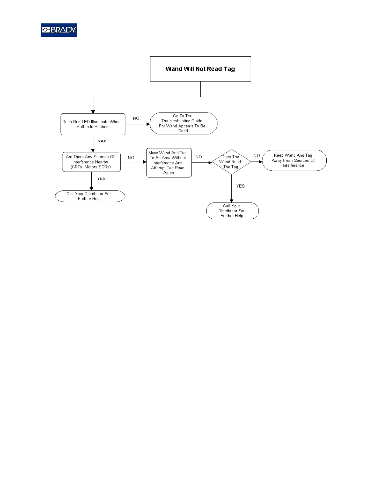
Troubleshooting Procedure
If you should experience problems in the normal usage of your Brady Wand the following
troubleshooting procedure will help in determining the cause of the problem and a possible
solution to the problem.
Brady Wand Users Guide Copy write 1998,WH Brady
2000-0001
17
Page 18
RFID Systems
Brady Wand Users Guide Copy write 1998,WH Brady
2000-0001
18
Page 19

RFID Systems
Brady Wand Users Guide Copy write 1998,WH Brady
2000-0001
19
Page 20

RFID Systems
Brady Wand Users Guide Copy write 1998,WH Brady
2000-0001
20
 Loading...