

Page 1

Brady
Bradyprinter Models 2461, 3481, and 6441
Operator’s Manual
(TEMP COVER)
(DO NOT PRINT)
(DO NOT print this page)
Page 2

(DO NOT print this page)
Page 3

Copyright Information:
CG Triumvirate is a trademark of Agfa Corporation.
CG Times based upon Times New Roman under license from the Monotype Corporation.
Firmware (Software) Agreement
The enclosed Firmware (Software) resident in the Printer is owned by Licensor or its
suppliers and is licensed for used only on a single printer in the user’s Trade or Business.
The User agrees not to, and not to authorize or permit any other person or party to
duplicate, or copy the Firmware or the information contained in the non-volatile or
programmable memory. The firmware (Software) is protected by applicable copyright
laws and Licensor retains all rights not expressly granted. In no event will Licensor or its
suppliers be liable for any damages or loss, including direct, incidental, economic,
special, or consequential damages, arising out of the use or inability to use the Firmware
(Software).
Information in this document is subject to change without notice and does not represent a
commitment on the part of Brady Worldwide, Inc. No part of this manual may be
reproduced or transmitted in any form or by any means, for any purpose other than the
purchaser's personal use, without the expressed written permission Brady Worldwide Inc.
All rights reserved. Printed in the United States of America.
© Copyright 2000 by Brady Worldwide, Inc.
Part Number: 88-2241-21
Revision: C
Page 4
Agency Compliance and Approvals:
UL1950 Information Technology Equipment
C US
Listed
C22.2 No. 950-M93
EN60950
For 230 Volt Operation (Europe): Use a cord set, marked “HAR,”
consisting of a min H05VV-F cord which has a minimum 0.75 square
mm diameter conductors, provided with an IEC 320 receptacle and a
male plug for the country of installation rated 6A, 250V
Für 230 Volt (Europa): Benützen Sie ein Kabel, das mit “HAR”
markiert ist, bestehend mindestens aus einem H05VV-F Kabel, das
mindestens 0,75 Quadratmillimeter Drahtdurchmesser hat; sowie eine
IEC320 Steckdose und einen für das Land geeigneten Stecker, 6A,
250 Volt.
As an Energy Star Partner, the manufacturer has determined that this
product meets the Energy Star guidelines for energy efficiency.
The manufacturer declares under sole responsibility that this product
conforms to the following standards or other normative documents:
EMC: EN 55022 (1993) Class B
EN 50024 (1998)
Safety: This product complies with the requirements of
EN 60950/All:1997
Gost-R
Resolution S.I.C. & M., No. 799/99
FCC: This device complies with FCC CFR 47 Part 15 Class A.
þ Note: This equipment has been tested and found to comply with the limits for a
Class A digital device, pursuant to Part 15 of the FCC Rules. These limits
are designed to provide reasonable protection against harmful
interference when the equipment is operated in a commercial
environment. This equipment generates, uses, and can radiate radio
frequency energy, and if not installed and used in accordance with the
instructions in this manual, it may cause harmful interference to radio
communications. Operation of this equipment in a residential area is likely
to cause harmful interference in which case the user will be required to
correct the interference at his own expense.
Page 5

Important Safety Instructions:
The exclamation point within an equilateral triangle is intended to
alert the user to the presence of important operating and
maintenance instructions in the literature accompanying this unit.
This unit has been carefully designed to provide years of safe, reliable
performance. However, as with all electrical equipment, there are some basic
precautions that you follow to avoid personal injury or damage to the printer:
Ø Before using the printer, carefully read all the installation and operating
instructions.
Ø Observe all warning instruction labels on the printer.
Ø Install the printer on a flat, firm surface.
Ø Do not place the printer on or near a heat source.
Ø To protect your printer from overheating, make sure no openings on the
printer are blocked.
Ø Never insert anything into the ventilation slots and openings of the printer.
Ø Do not use the printer near water or spill liquid into it.
Ø Ensure that the AC power source matches the ratings listed for the printer.
(If unsure, check with your dealer or local utility provider.)
Ø Do not place the AC power cord where it can be stepped on. If the AC
power cord becomes damaged or frayed, replace it immediately.
Ø If the printer ever needs repair, consult only qualified, trained service
personnel. No user-serviceable parts are inside; do not remove the cover.
Page 6

Page 7

Printer Overview
1.0 About the Printer ...........................................................1
1.0.1 Standard Features...........................................2
1.0.2 Optional Features ...........................................2
1.1 Option Installation .........................................................5
1.2 Hardware Components .................................................6
Getting Started
2.0 Unpacking the Printer ...................................................7
2.0.1 Inspection ........................................................8
2.0.2 Additional Requirements .................................8
2.1 Media and Ribbon Selection .........................................9
2.1.1 Print Quality Controls.......................................9
Setting Up the Printer
3.0 Installation...................................................................11
3.0.1 Communications............................................12
3.1 Loading Media ............................................................14
3.1.1 Roll Media .....................................................15
3.1.2 Fan-Fold Media .............................................16
3.2 Media Sensor Adjustment...........................................17
3.3 Loading Ribbon...........................................................18
3.4 Quick Media Calibration..............................................20
3.5 Outputting Labels........................................................21
3.5.1 Rewinding......................................................21
3.5.2 On-Demand Dispensing ................................23
3.5.3 Cutting ...........................................................25
i
Page 8

Using the Front Panel
4.0 Operation ....................................................................27
4.0.1 Ready Mode: Normal Operation ....................27
4.0.2 Menu Mode: Configuration ............................28
4.0.3 Quick Test Mode: Print Test Labels...............29
4.0.4 Indicator Lights ..............................................30
4.0.5 LCD ...............................................................30
4.0.6 Resetting the Printer......................................31
4.0.6.1 Soft Reset ........................................31
4.0.6.2 Level One Reset ..............................31
4.0.6.3 Level Two Reset ..............................31
4.1 The Menu System.......................................................32
4.1.1 Entrance and Exit Prompts ............................33
4.1.2 Media Settings...............................................34
4.1.3 Print Control ..................................................35
4.1.4 Printer Options...............................................37
4.1.5 System Settings.............................................39
4.1.6 Communications............................................47
4.1.7 Diagnostics ....................................................53
4.2 Display Messages.......................................................54
4.2.1 User Prompts and Condition Messages ........54
4.3 Quick Test Mode.........................................................56
4.3.1 Print Quality Label .........................................56
4.3.2 Configuration Label .......................................57
4.3.3 Quick Ribbon Test Label ...............................58
4.3.4 Dot Test Pattern Label...................................59
4.3.5 Validation Label .............................................60
4.3.6 User Defined Label ........................................60
Maintenance and Adjustments
5.0 Media Sensor Calibration............................................61
5.0.1 Standard Calibration......................................61
5.0.2 Advanced Entry Calibration ...........................65
5.1 Printhead Adjustments................................................71
5.1.1 Leveling Cam Adjustment..............................71
5.1.2 Burn Line Adjustment ....................................72
ii
Page 9

5.2 Printhead Replacement ..............................................73
5.3 Maintenance Schedule ...............................................74
5.3.1 Cleaning the Printhead ..................................75
5.3.2 Cleaning the Platen Roller .............................76
5.3.3 Cleaning Interior and Exterior Surfaces .........77
5.4 Application Version Updates.......................................77
5.4.1 Updating from Ready Mode...........................78
5.4.2 Updating from Download Mode .....................79
5.4.3 Possible Problems during an Update ............80
5.5 Boot Loader Program Updates ...................................81
Troubleshooting
6.0 Problem Resolution.....................................................83
6.1 Fault and Warning Messages .....................................87
6.2 Hex Dump Mode .........................................................93
Specifications
7.0 General Specifications ................................................95
7.1 Media and Ribbon Requirements................................97
Appendix A
ASCII Control Code Chart...................................................99
Appendix B
Available Fonts and Bar Codes.........................................101
Appendix C
Module Assignments.........................................................109
Print Resolutions and Maximum Label Widths..................109
Available Speeds and Default Settings .............................110
iii
Page 10

Appendix D
GPIO Port Description ......................................................111
Appendix E
Menu System Multi-Language Support.............................113
Advance File Handling Information ...................................116
Appendix F
Saving a Configuration File...............................................119
Warranty Information ................................................121
Glossary........................................................................125
Index ...............................................................................129
iv
Page 11
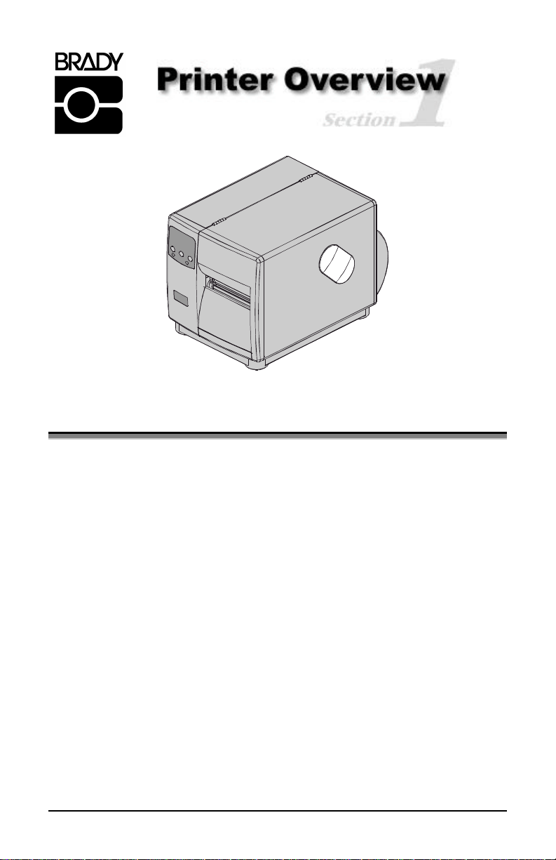
1.0 About the Printer
Congratulations on your purchase of a Bradyprinter Model 2461, 3481, and
6441 hereafter referred to as ‘the printer’, blends the rugged durability of diecast construction with state-of-the-art electronics and user-friendly features to
redefine the standard in industrial thermal printers.
This manual provides all the information necessary for everyday printer
operation. To begin printing labels, refer to the instructions provided with the
label-creation software you have chosen. If you wish to write custom label
programs, a copy of the Programmer’s Manual is included on the enclosed
Accessories CD.
To grow with all of your printing needs, the design of the printer allows most
upgrades to be performed easily by an operator; see Section 1.1. The following
subsections detail the standard features, available options and a hardware
overview.
1
Page 12
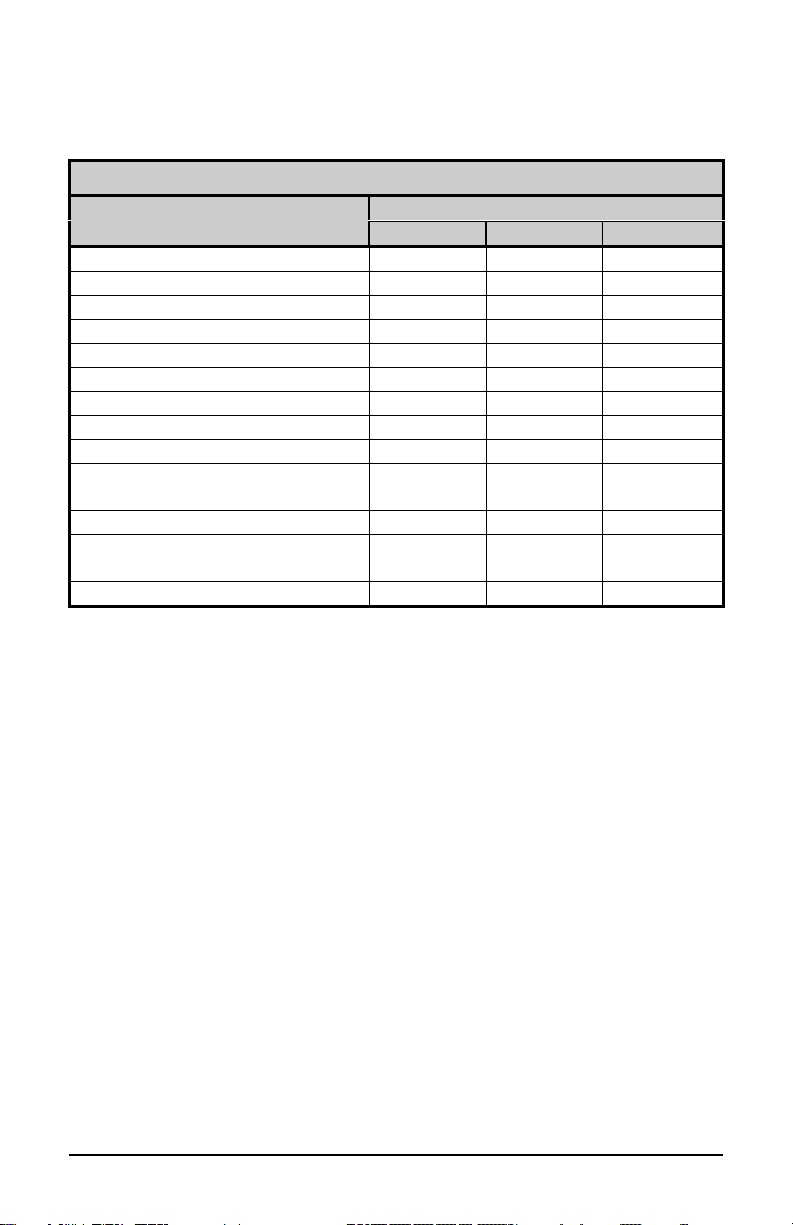
1.0.1 Standard Features
This printer offers the following standard features:
Bradyprinter Standard Features Listing
Feature
Printhead Density (Dots Per Inch) 203 300 600
Direct Thermal Printing X X X
On-Demand and Batch Printing X X X
Rotating Media Hub X X X
Media Tear Bar X X X
Fan-fold media capability X X X
Flash memory 1MB 2MB 2MB
SDRAM 8MB 16MB 16MB
RS-232 interface port X X X
IEEE 1284 Compliant parallel
interface port
Liquid Crystal Display X X X
EFIGS (multi-language display
and configuration label support) X X X
AGFA Scalable font engine X X X
2461 3481 6441
X X X
Model
1.0.2 Optional Features (available except as noted)
The printer offers the following optional features:
Light-Duty (Backing-Only) Cutter
A rotary-type mechanism to automatically cut material with a maximum
thickness of .005” (.127mm) into minimum lengths of 1.25 inches (31.8 mm).
Standard Cutter
A rotary-type mechanism to automatically cut material with a maximum
thickness of .010” (.254mm) into minimum lengths of 1.25 inches (31.8 mm).
Cutter Tray
An adjustable tray that will collect and hold up to 200 cut labels or tags.
2
Page 13

External Keyboard Support
An interface for the connection of the Passport™ keyboard.
External Media Rewinder
Separate device with and 8” roll capacity to rewind labels and backing material.
Font Expansion Card (cannot be used with the I/O Expansion card)
A slide-in circuit card assembly with 8MB Flash memory expansion for
International Language Printing Capability (ILPC) and/or additional fonts and
graphics. ILPC consists of one of the following:
Ø CG-Times (Western European) Scalable font
Ø Kanji Gothic B Scalable font
Ø Simplified Chinese GB Scalable font
Ø Korean Hangul Scalable font
Internal Media Rewinder
An internal hub with a six-inch outer diameter capacity to wind printed labels, or
only backing material when a Peel and Present Mechanism is attached.
ILPC – CG Times Firmware
The printer’s firmware can be upgraded to include the ILPC CG Times font.
This supports the Enhanced Language Code Pages.
I/O Expansion Card (specify features at time of order)
Standard features* of this slide-in circuit card assembly include:
Ø General purpose (GPIO) interface for external printer and device control.
Ø Time and date calendar (Real Time Clock) function for label time stamping.
Optional feature:
Ø 8 MB Flash memory expansion for graphics and/or additional fonts
including International Language Printing Capability (ILPC).
LAN Interface
A slide-in circuit card assembly that provides for network connectivity, allowing
multiple users on various platforms to share the same printer.
*Item unavailable for the 2461 model
3
Page 14

Peel and Present Mechanism (requires the Internal Rewind option)
An output control device that automatically separates printed labels from the
backing material and allows subsequent printing to occur only after the removal
of a previously printed label. Minimum label length for peeling is 1.5 inches (38
mm).
Present Sensor
An output control device that allows subsequent printing to occur only after the
removal of a previously printed label.
RS-422 Serial Interface*
Single-drop interface hardware to support greater distances from the host at
communication rates of up to 38,400 baud.
Thermal Transfer (specify configuration at time of order)
A printing method that uses ribbon to produce exceptional image clarity, as
compared to most direct thermal media types. This option must be specified for
use with either ‘coated side in’ ribbon or ‘coated side out’ ribbon.
Twinax/Coax Interface
A slide-in circuit card assembly that provides connectivity to AS/400 and
System/3X Twinax host system or 3270-type host system. Cable included.
*Item unavailable for the 2461 model.
4
Page 15
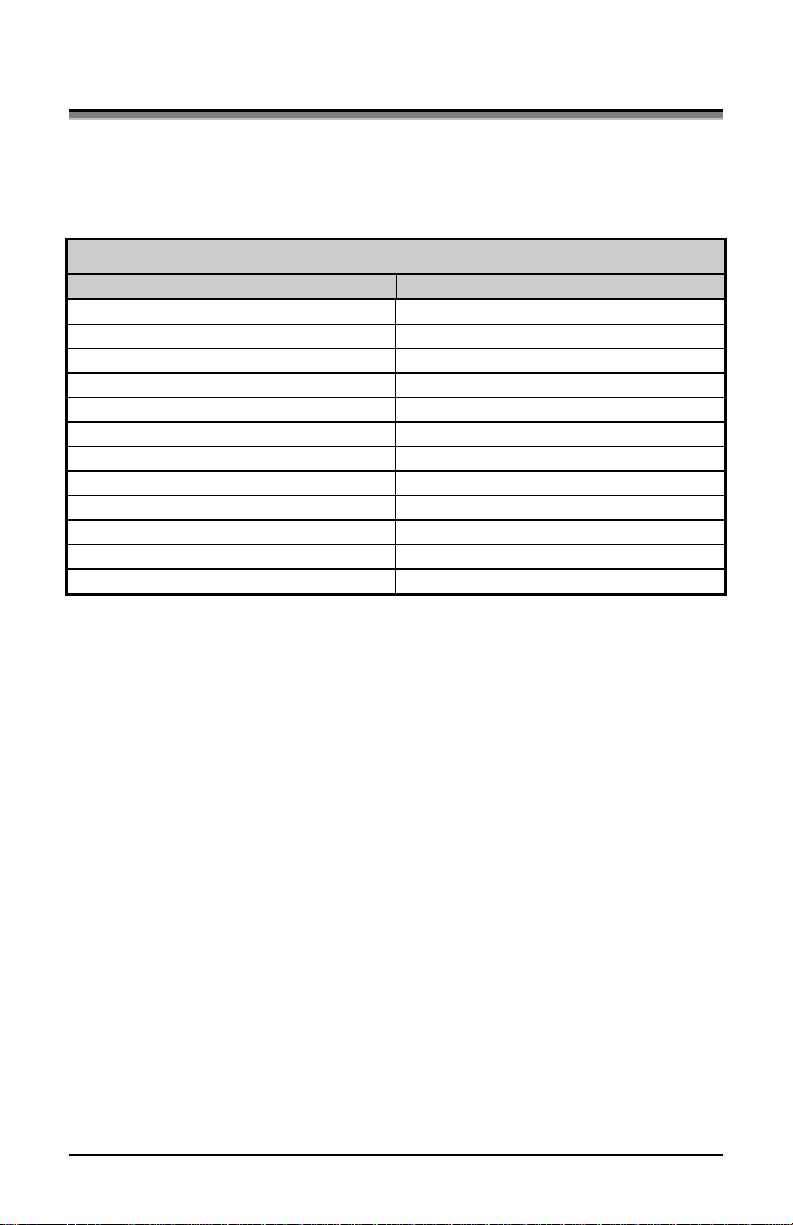
1.1 Option Installation
The following table lists the available options and the recommended
qualification level of the installer. For detailed information concerning a specific
option, contact your dealer or Technical Support.
Suggested Experience Level for Option Installation
Option Qualified Installer
Cutter Tray Operator
Cutters: Light and Standard Duty Operator
Passport External Keyboard Operator
Font Expansion Card Certified Technician
Internal Rewind Operator
I/O Expansion Card Certified Technician
LAN Interface Certified Technician
Peel and Present Mechanism Operator
Present Sensor Operator
RS-422 Serial Interface Certified Technician
Thermal Transfer Assembly Operator
Twinax/Coax Interface Certified Technician
5
Page 16
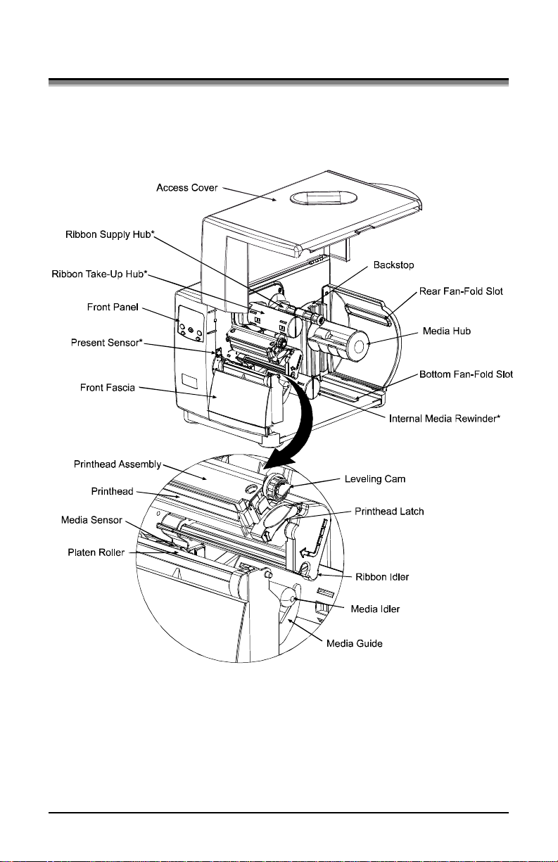
1.2 Hardware Components
The following drawing highlights the user-assessable components of the printer.
Items denoted with an asterisk (*) are optional equipment.
6
Page 17
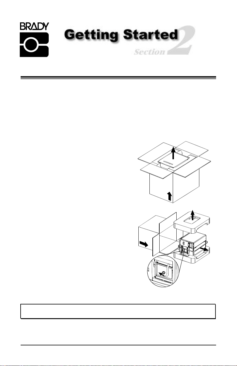
2.0 Unpacking the Printer
Inspect the shipping container(s) for damage; if evident, immediately notify the
shipping company to report the nature and extent of the damage.
The printer has been carefully packaged to avoid damage during transit. In order
to operate the printer, you will need to remove the tape and foam placed there
for shipment. Complete the following steps prior to connecting power or
attempting to load media.
ΠWith the arrow on the box pointing up,
open the box.
• Remove Accessories Box.
Ž Tilt the printer on its side and slide the
printer out of its box.
• Place the printer in an upright position
and remove the packing foam, plastic
bag, and tape.
þ Note: It is a good idea to save the carton and packaging materials in the
event that future shipment is required.
7
Page 18
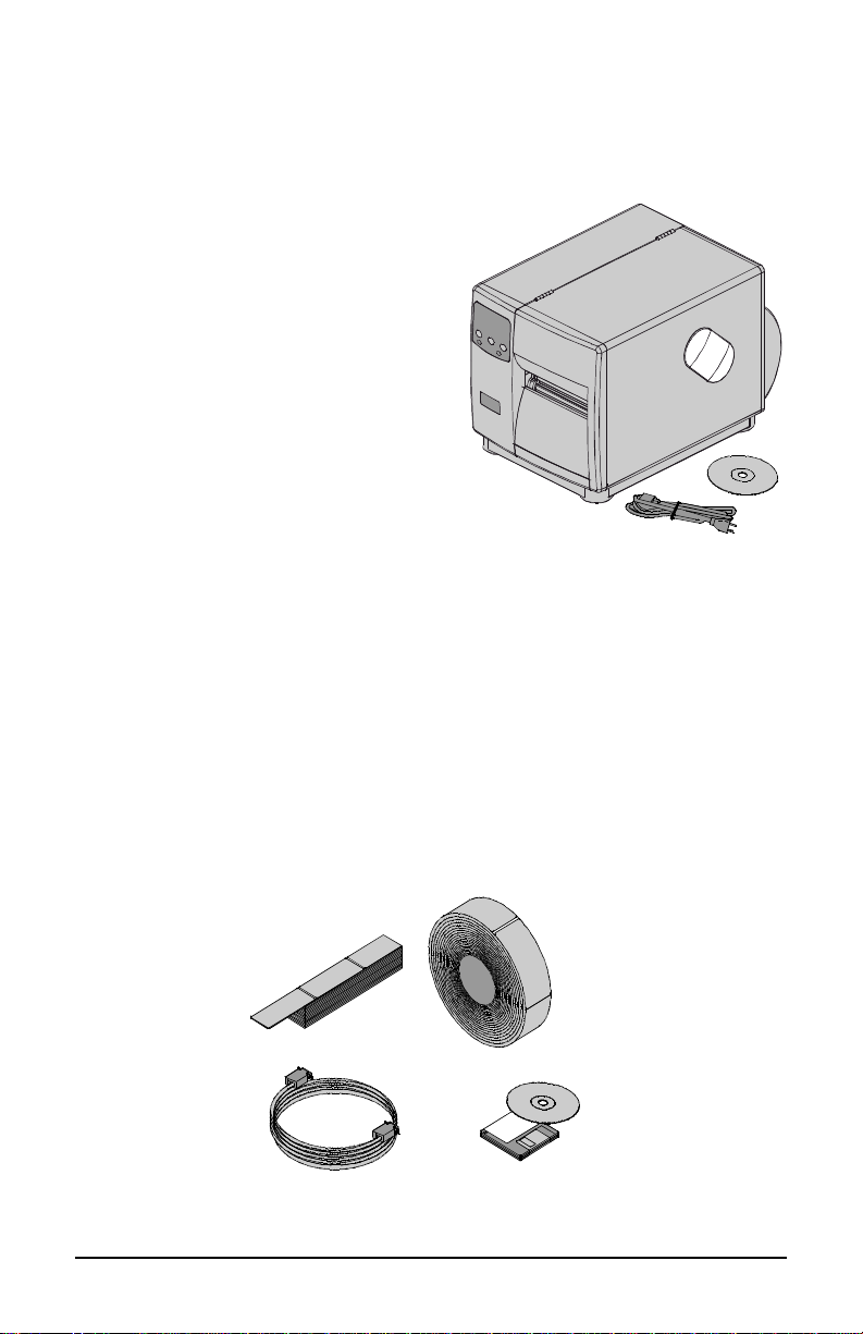
2.0.1 Inspection
After removing the printer from the packaging material, check the contents of
the package. In addition to this manual, the following items should be included:
Ø Printer
Ø Power Cord
Ø Accessories CD
Ø Any special or additionally
purchased items.
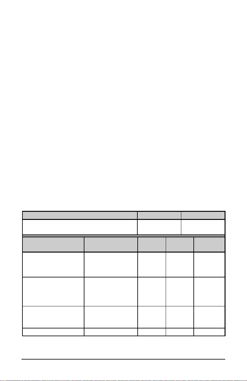
2.0.2 Additional Requirements
The following items are necessary to produce labels. Contact your dealer or a
customer support representative for advice on which media and software may
best suit your needs.
Ø A serial or parallel interface cable; see Section 3.0.1
Ø Applicable media; see Section 2.1 for suggestions and Section 7.1 for
requirements.
Ø Applicable software
8
Page 19

2.1 Media and Ribbon Selection
The following is a limited overview of media characteristics. For complete
information and advice regarding your specific application needs, always
consult a qualified media specialist or a Media Representative.
Media Selection – Direct Thermal
Consider three important factors when selecting direct thermal stock:
• The abrasive qualities of the material that covers the thermal reactive layer
of the paper.
• The ability of that layer to control the chemical reaction that occurs when
the image is “burned”.
• The amount of heat required to create an image on the paper.
Media Selection – Thermal Transfer
Consider three important factors when selecting thermal transfer media
combinations:
• The label top coating and ribbon combinations affect image quality.
• Ribbon backcoating is highly recommended. It provides protection for the
printhead, and may also provide an anti-static coating.
• For additional printhead protection, use ribbon with a slightly greater width
than the overall width of the label and backing material.
2.1.1 Print Quality Controls
The printer provides flexibility with a comprehensive set of print controls. Of
these, the amount of heat applied by the printhead and the rate of media
movement will have the most effect on the barcodes, text, and graphics being
printed. Low cost direct thermal stocks, for example, have raised reaction
temperatures and therefore require higher heat values and slower print speeds to
make a clear image on the media. In general, there are four methods of
controlling print quality:
• The first is the ‘Media Type’ menu setting, which should be set to match the
media being used. For example, when printing with ribbon use the thermal
transfer setting.
9
Page 20
• The second method would be to change the ‘Print Control / Heat’ menu
setting (selectable as ‘Heat Setting’ in most software programs). Increasing
this value causes more energy to be transferred to the media, resulting in a
darker image. If the image is too dark, reduce this value or increase the print
speed.
• The next method would be to change the ‘Print Control / Print Speed’ menu
setting (also selectable as ‘Print Speed’ in most software programs).
Changing the print speed changes the amount of time the media is under the
printhead. Slowing the speed allows more time and control for energy to be
transferred. Increasing the speed will increase throughput, but may require a
higher heat setting.
• The final method, providing only subtle contrast changes, would be to
change the ‘Custom Adjustments / Darkness’ menu setting.
You will find that printing barcodes and detailed images on less expensive direct
thermal and thermal transfer media at higher speeds can be tricky. At one heat
setting, the images will fade and at the next higher heat setting, the images will
bleed. This is because the reaction temperature of the media is so high that at
higher rates of speed, it cannot react fast enough. To print fine images at higher
speed, media with lower reaction or release temperatures are required. On the
slower end of the print rate settings, crisper images are possible because the
media is not being stretched beyond its limits.
The following table is intended for reference only (for specific application
information, consult your media specialist or a Media Representative).
Direct Thermal Media Type Print Speed* Print Energy
Fasson 300 HD Direct Thermal Facesheet
Fasson 300 MD Direct Thermal Facesheet
Thermal Transfer
Media Type
Ribbon
Type
Great Label TTL GPR Plus
10-12**
Print
Speed*
Print
Energy
10-12** Medium Medium
Medium
Image
Durability
MaxWax
IIMAK Versamark
Coated Paper,
Wax 2 - 10 Low Low
Uncoated Paper, Tag
Stock, Some Films,
Some Synthetics
Coated Paper, Glossy
Wax/Resin 2 - 8 Medium High
Paper, Tag Stock,
Some Synthetics, Films
Synthetics, Films Resin 4 - 6 High High
*Values given in inches per second (IPS)
**Highly recommended for optimum print quality at speeds above 10 IPS.
10
Page 21
+
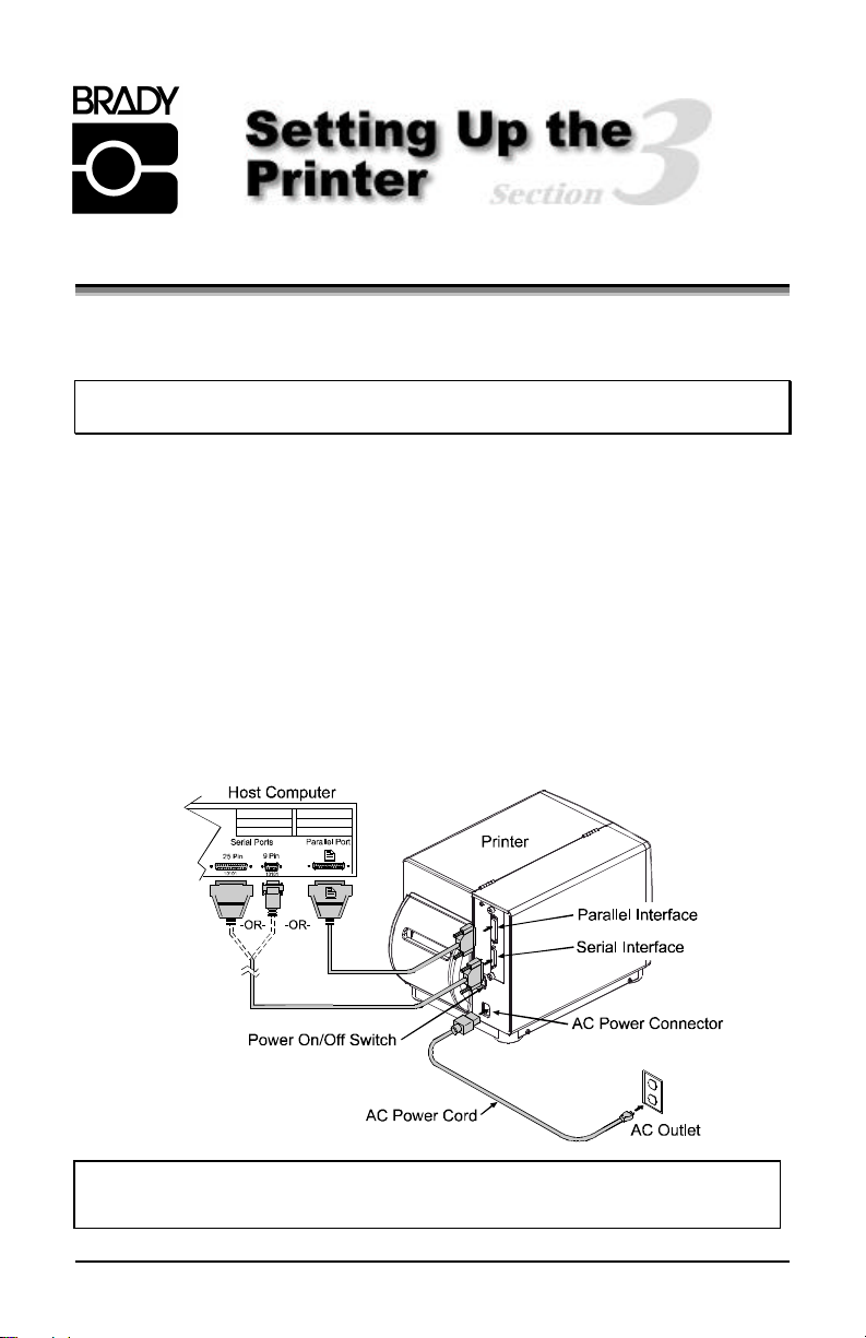
3.0 Installation
This section explains how to connect the printer, and load it with media and
ribbon.
þ Note: When connecting the AC Power Cord or interface cables to the printer,
ensure the Power On/Off Switch is in the ‘Off’ position.
ΠPlace the printer on a firm, level surface.
• Turn ‘Off’ the Host Computer and ensure that the Power Switch on the
Printer is in the ‘Off’ position.
Ž Depending upon your interfacing requirements, connect the appropriate
interface cable between Host Computer and Printer; see Section 3.0.1.
• Connect the AC Power Cord to the receptacle on the back of the Printer,
and then plug the AC Power Cord into a properly grounded outlet. (The
power supply in the printer automatically detects, then adjusts to the applied
line voltage; see Section 7.0 for the acceptable voltage ranges.)
If connecting the printer to a network, refer to the additional
documentation supplied with the network option.
11
Page 22
3.0.1 Communications
Using a data detection process, the interface selection occurs automatically in the
printer. At power-up, the printer begins monitoring the interface ports for
activity. When the host transmits data, the printer port detecting this data is set
‘active’ and remains active as long as data flow continues. Once the incoming
(received) data flow stops and the Host Timeout Value (see Section 4.1.6) is
exceeded, the detection process will be repeated. In addition, should the data
flow stop before a complete label format is received, the format will be ignored
and must be sent to the printer again.
þ Note: To change an active port immediately, cycle the printer power ‘Off’
and ‘On’.
Parallel Port:
The parallel interface has two menu-selectable modes of operation: unidirectional or bi-directional. Uni-directional mode is forward channel
communication and requires a Centronics cable with a 36 pin male connector.
Bi-directional mode is IEEE 1284 Compliant, using forward and reverse channel
communications. In this mode, data can be sent to the host provided it is also
IEEE 1284 Compliant and has supporting software. This mode requires an IEEE
1284 cable with a Centronics 36 pin male connector.
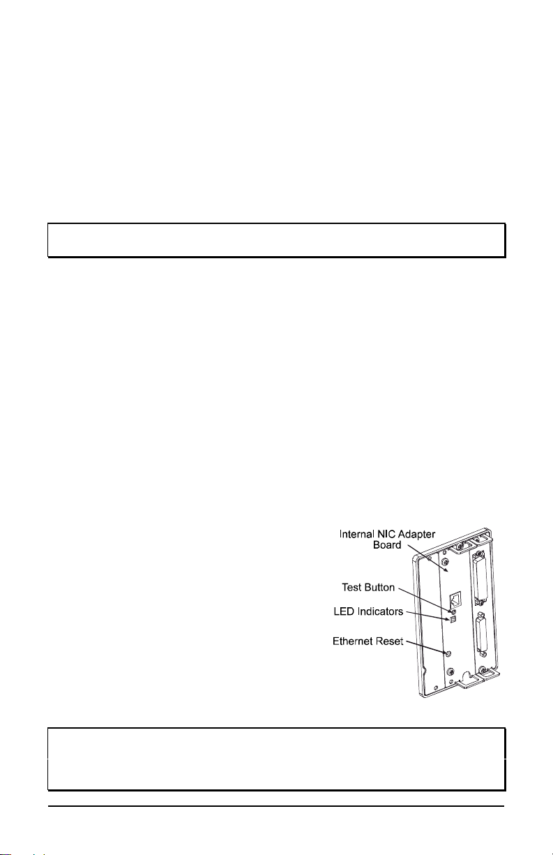
NIC Adapter (optional):
The NIC Adapter has several menu-selectable modes; see Section 4.1.6 for
details. Refer to the information provided with the option for connection
requirements. The following items are accessible from the back of the printer:
• The LED Indicators provide operational
information: A green LINK LED indicates
a good network connection. A green 100
LED indicates a 100BASE-T network
connection. The ACT LED (activity)
flashes green or red when the server is
ready for use.
• The Test Button will cause a NIC
Configuration label to print.
• The Ethernet Reset button will reset the
NIC Adapter .
þ Note: Following initialization, the printer will indicate ‘Ready’; however, the
NIC Adapter will not be ready to receive data until its ‘boot-up’ process
is completed. Depending upon the NIC Adapter configuration, this
process may take up to two minutes to complete.
12
Page 23
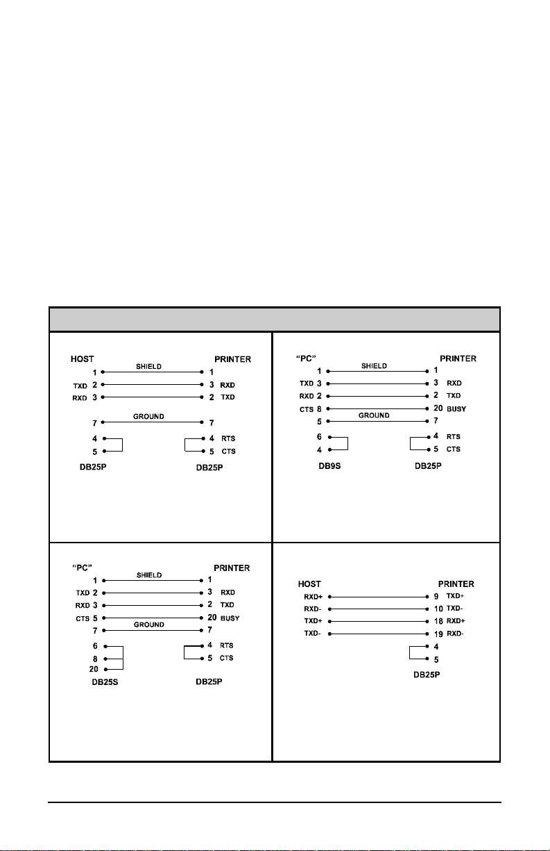
Serial Port:
The serial interface supports RS-232C and, if equipped, RS-422
communications. The following list of serial port settings is menu-selectable and
must match the host computer’s serial port settings; see Section 4.1.6.
• Baud Rate (serial communication speed)
• Word Length
• Word Parity
• Number of Stop Bits
• Handshaking Protocol
In addition to the port settings, the serial interface cable wiring must have
specific connections (pin-outs) for proper data exchange between the host
and printer. The different serial cable pin-outs, suggested applications, and part
numbers are shown below (contact your reseller for ordering information).
Serial Interface Cable Listing (all models, except as noted)
Null Modem (MXM) “PC” (DB9P) to Printer
Part Number 556000 Part Number 556001
For connection to other DCE equipment.
Flow control is only Xon/Xoff.
For connection to a PC compatible with
DB9P communication ports. Flow control
can be either Xon/Xoff or CTS/DTR.
“PC” (DB25P) to Printer RS-422 Connection
Part Number 556002 Part Number N/A
For connection to a PC compatible with
DB25 communication ports. Flow control
can be either Xon/Xoff or CTS/DTR.
Diagram provided only as a reference.
*
This optional interface is not available for
the 2461 model.
*
13
Page 24
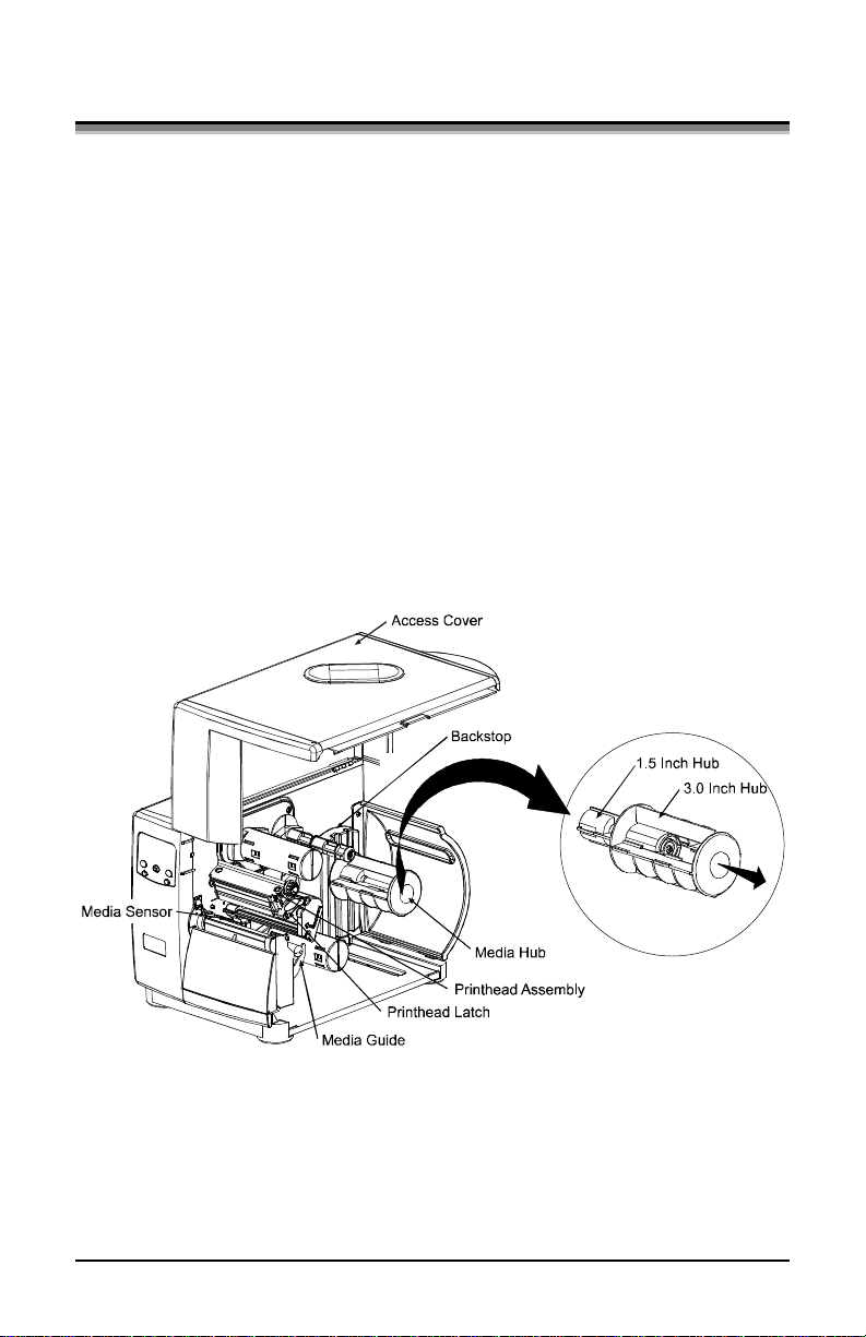
3.1 Loading Media
Begin loading as follows:
ΠRaise the Access Cover.
• Rotate the Printhead Latch forward and raise the Printhead Assembly.
Ž Slide the Media Guide out away from the frame and then lower it to the
down position.
• If using roll media, the Media Hub can accept 3.0-inch (76mm) and 1.5-
inch (38mm) cores. To use 1.5-inch cores, first slide off the 3 Inch Hub by
grasping and then pulling it firmly outward.
• Proceed according to the type of media you are using: either go to Section
3.1.1 for Roll Media or go to Section 3.1.2 for Fan-Fold Media.
14
Page 25
+
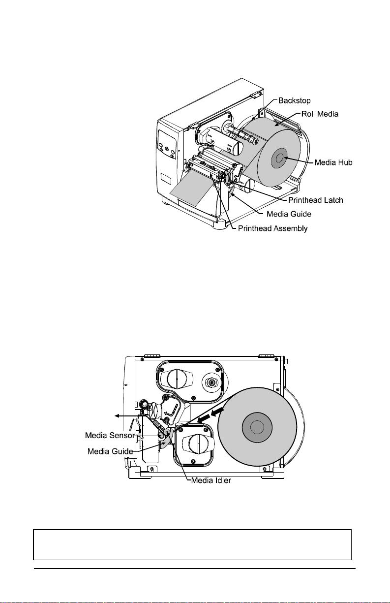
3.1.1 Roll Media
This loading method is roll type media applications. To load:
ΠSlide the Roll Media
onto the Media Hub
until it rests against the
Backstop.
• Route the media as
shown: under the
Media Idler, through
the Media Sensor, then
out the front of the
printer.
Ž Raise and slide the
Media Guide over until
it rests lightly against the edge of the media.
• Position the Media Sensor; see Section 3.2.
• If your application uses thermal transfer media, load ribbon (see Section
3.3); otherwise continue.
‘ Lower the Printhead Assembly and rotate the Printhead Latch completely
back into the locked position. Close the Access Cover.
’ Turn ‘On’ the printer. After ‘Ready is displayed, press and hold the FEED
key until at least one label gap or mark is advanced; see Section 3.4.
If using less than full width media, adjust the Leveling Cam; see
Section 5.1.1.
15
Page 26
+
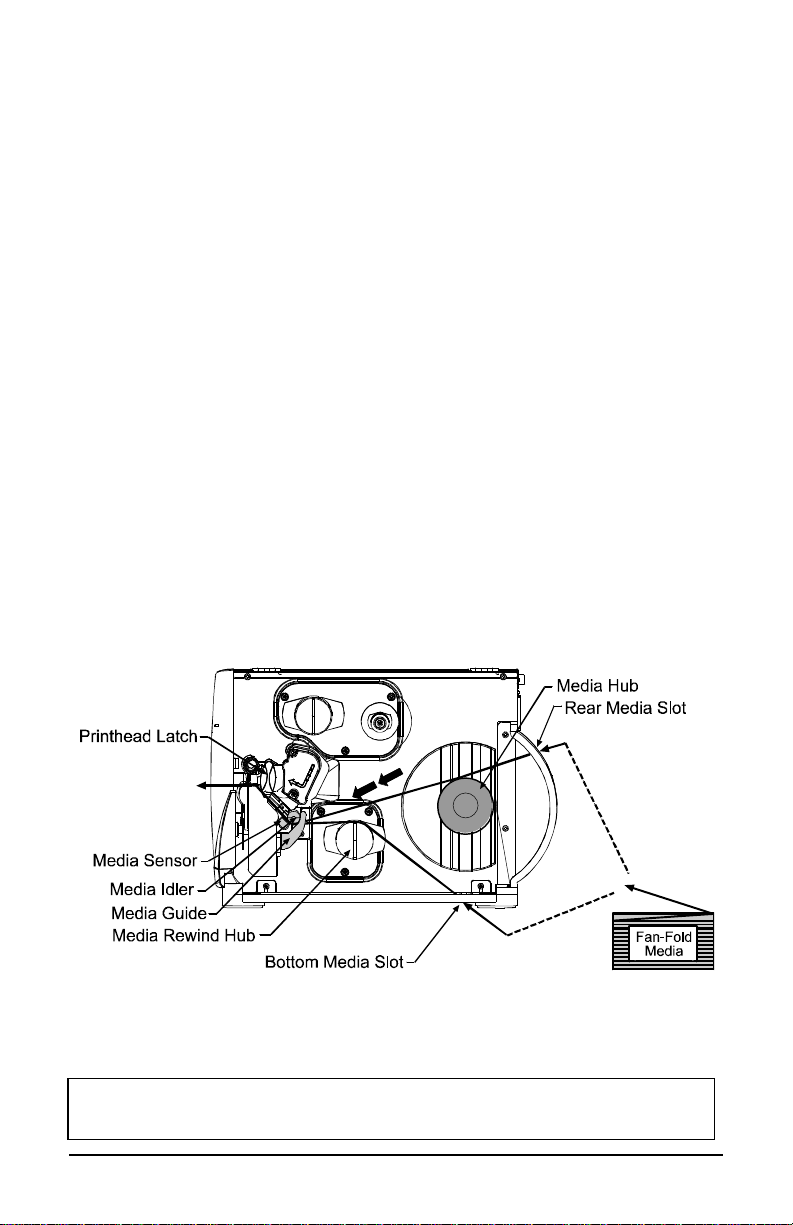
3.1.2 Fan-Fold Media
This loading method is for tag and fan-fold type media applications. To load:
ΠBring the media in through the Bottom or the Rear Media Slot. (If using
reflective stock, ensure that the mark is facedown.)
• Depending upon the entry point, route the media as shown: if through the
Rear Media Slot, route the media over the Media Hub; or, if through the
Bottom Media Slot, route the media over the Media Rewind Hub.
Ž Continue routing the media under the Media Idler, through the Media
Sensor and out the front of the printer.
• Raise and slide the Media Guide over until it rests lightly against the edge
of the media.
• Position the Media Sensor; see Section 3.2.
‘ If your application uses thermal transfer media, load ribbon (see Section
3.3); otherwise continue.
’ Lower the Printhead Assembly and rotate the Printhead Latch completely
back into the locked position. Close the Access Cover.
“ Turn ‘On’ the printer. After ‘Ready is displayed, press and hold the FEED
key until at least one label gap or mark is advanced; see Section 3.4.
If using less than full width media, adjust the Leveling Cam; see
Section 5.1.1.
16
Page 27
*
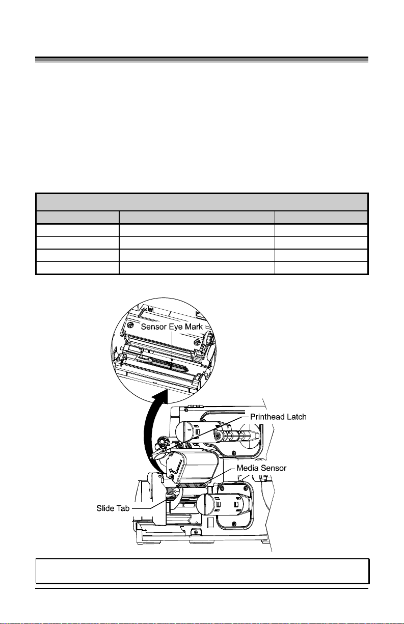
3.2 Media Sensor Adjustment
The Media Sensor needs to be positioned so that the printer can detect the
presence of media and the top-of-form (except for continuous stock, where the
TOF is set through programming; see Label Length, Section 4.1.2). To adjust:
ΠWith media loaded, as described in Section 3.1.1 or 3.1.2, grasp the Slide
Tab and move the Sensor Eye Mark into position over media according to
the table below.
• If loading media, return to the media loading instructions.
Media Sensor Selection and Adjustment
Media Type Sensor Eye Mark Position
Die-cut Near the middle of the label Gap
Notched Centered over the notch Gap
Reflective Centered over the black mark Reflective
Continuous Near the middle of the media Continuous
*
See Section 4.1.2 for Sensor Type selection.
Sensing Required
þ Note: Changes to the start of print position can be made using the Print
Control/Row Adjust or Row Offset (see Section 4.1.3).
17
Page 28
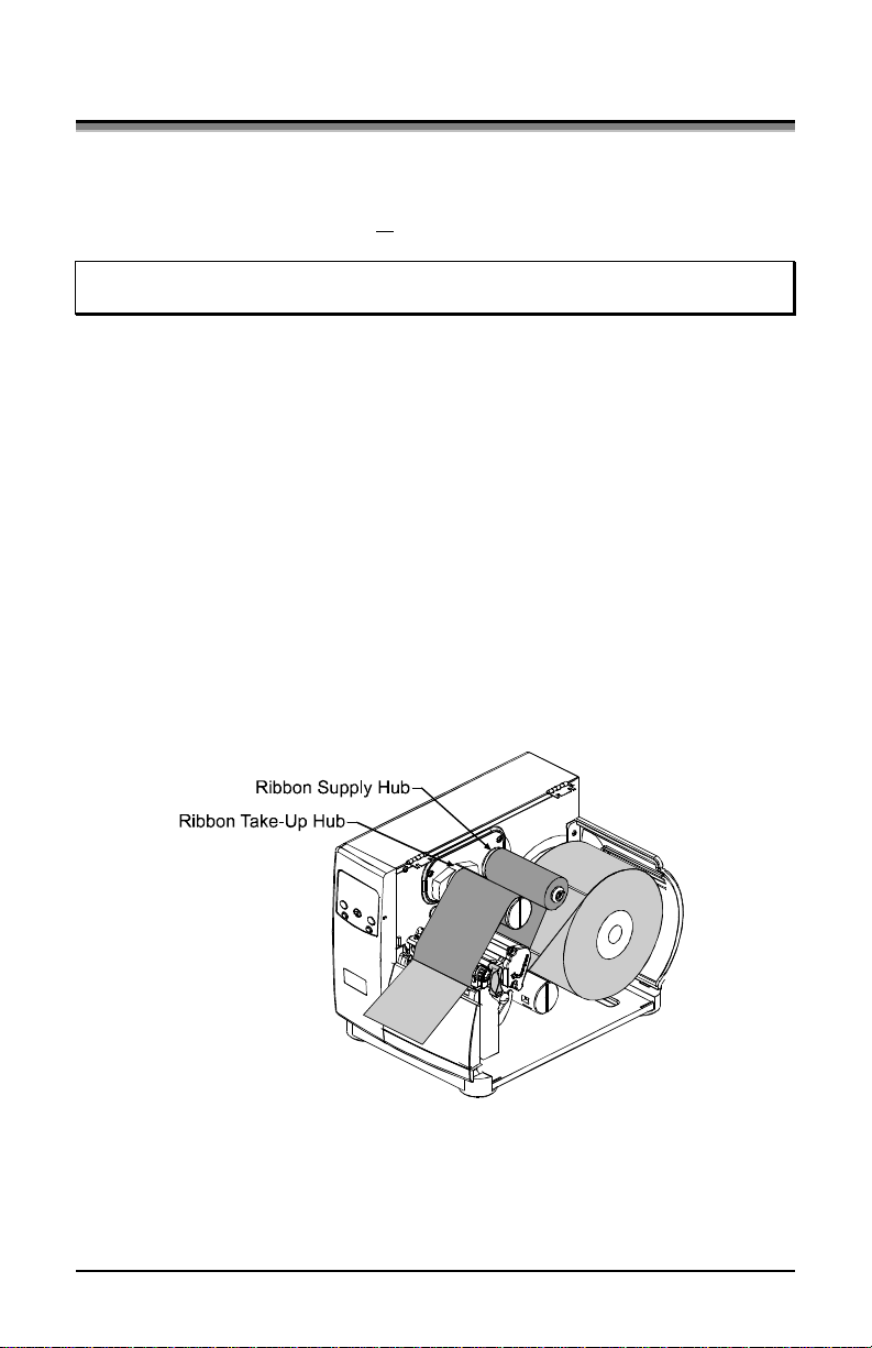
3.3 Loading Ribbon
Ribbon is required with thermal transfer media. Depending upon the type of
Ribbon Supply Hub (see the next page for examples), the printer must use either
ribbons with the ‘coating side in’ or ribbons with the ‘coating side out’. To load:
þ Note: Using a ribbon that is slightly wider than your media (and liner, if any)
will help protect against printhead wear.
ΠWith the access cover raised and the printhead assembly up, position the
ribbon to be dispensed in the direction appropriate for the Ribbon Supply
Hub.
• Slide the ribbon onto the Ribbon Supply Hub until it rests against the hub’s
flange.
Ž Route the ribbon under the Ribbon Idler, out the front of the printer and
then up around to the Ribbon Take-Up Hub, winding it several times in a
clockwise direction to secure it in place.
• If loading media, return to the media loading instructions. Otherwise, lower
the Printhead Assembly and rotate the Printhead Latch completely back into
the locked position. Close the Access Cover.
Removal:
When the supply is exhausted, pull the empty core from the Ribbon Supply
Hub and discard it. To remove used ribbon: grasp the Ribbon Take-Up Hub,
pull outward, then squeeze to collapse the hub and take off the ribbon.
18
Page 29
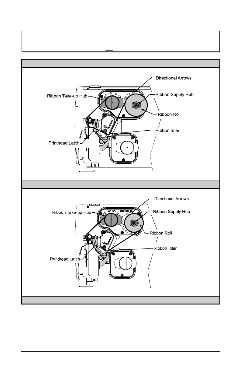
þ Note: Directional Arrows near the Ribbon Supply Hub indicate the correct
ribbon route. Ribbon is available with the ink (coating) layer wound ‘in’
or ‘out’. These types are not interchangeable for use with the printer.
Ribbon Routing Diagrams
‘Coating Side In’ Ribbon Supply Hub
‘Coating Side Out’ Ribbon Supply Hub
19
Page 30

3.4 Quick Media Calibration
+
At the factory, the printer is calibrated to sense a wide range of media types.
Quick Media Calibration fine-tunes the media sensor for your gap, notch or
reflective media application (this is not required for continuous media). Perform
this calibration during initial set-up or after changing your media type. To
calibrate:
ΠEnsure that media is loaded (see Section 3.1), that the Media Sensor is
• Press and hold the FEED key. The printer will begin advancing media;
Upon successful completion, the ‘Calibration Completed’ message will flash;
the printer will feed to the next label TOF and ‘Ready’ will be displayed. (A
‘Warning Low Backing’ message may appear if using notched media or media
on a transparent liner; however, the calibration was successful).
þ Note: Media containing large gaps may require a change in the ‘Paper Out
When ‘Uncalibrated’ is displayed, follow the Media Sensor Calibration
procedure in Section 5.0.
adjusted (see Section 3.2), and that the printer is idle.
allow at least one label gap or mark to advance under the sensor during
this process.
Distance’ setting; see Section 4.1.2.
Calibration Hints:
In certain cases, the printer may have trouble differentiating between the label
and liner. If the printer stops feeding in the middle of a label or if ‘Cannot
Calibrate’ is displayed, try calibrating over a longer distance:
• Press and hold the FEED key to allow two gaps or marks to advance under
the sensor.
If the printer continues to stop in the middle of a label, or if ‘Cannot Calibrate’
is displayed again:
• Press and hold the FEED key to allow three or more gaps or marks to
advance under the sensor.
If this method also fails, see Media Sensor Calibration, Section 5.0.
20
Page 31

3.5 Outputting Labels
In addition to directly outputting labels from the printer, there are several
optional output configurations available.
3.5.1 Rewinding
With the Internal Media Rewinder option, the printer can wind the printed labels
and backing material. To rewind labels:
þ Note: When winding labels, do not allow the outer diameter of the roll to
exceed 6 inches (154 mm) on the Media Rewind Hub.
ΠRemove the Front Fascia.
• Remove the Tear Plate by
first removing the
Thumbscrew.
Ž Position the Rewind Plate
on the printer and install and
tighten the Thumbscrew.
• If installed, remove the
Rewind Retainer and Media
Clip from the Media
Rewind Hub (see drawing
next page).
• Load media as described in Section 3.1, press the FEED key and advance
approximately 20 inches (51 cm) of media.
21
Page 32

‘ Route the media back to the Media Rewind Hub, as shown below.
’ Insert the leading edge into a Slot on the Media Rewind Hub then insert the
Media Clip into a Slot to secure it in place.
“ Position the Rewind Retainer lightly against the edge of the media on the
Media Rewind Hub. Tighten the Thumbscrew to secure the retainer in
place.
” Manually rotate the Media Rewind Hub to remove any slack in the media.
Close the Access Cover.
Removal:
Remove the Rewind Retainer and Media Clip. Grasp the end of the hub. While
pulling outwardly, squeeze the hub together to collapse it and then slide off the
labels.
22
Page 33

3.5.2 On-Demand Dispensing
When equipped with the Peel and Present option, labels are dispensed from the
printer one at a time, separated automatically from the liner for immediate
application.
ΠWith the Peel and Present
Mechanism installed on the
printer, pull outward on the
Latch and allow the Roller
Bracket to swing forward.
• With media loaded as
described in Section 3.1, press
the FEED key to advance
approximately 20 inches (51
cm) of media. Remove all of
the labels from the backing
material.
Ž Route the backing material through the Roller Bracket as shown (the
backing should go under the top black roller, then out).
• Raise the Roller Bracket up to its latched position.
23
Page 34

+
• If installed, remove the Media Clip and the Rewind Retainer from the
Media Rewind Hub. Route the Backing Material around the Media Rewind
Hub, as shown.
‘ Insert the leading edge into a Slot on the Media Rewind Hub then insert the
Media Clip into a Slot to secure it in place.
’ Position the Rewind Retainer lightly against the edge of the backing on the
Media Rewind Hub. Tighten the Thumbscrew to secure the retainer in
place.
“ Manually rotate the Media Rewind Hub to remove any slack in the media.
Close the Access Cover.
For on-demand printing, ensure that the Present Sensor has been
enabled; see Section 4.1.4.
Removal:
Remove the Rewind Retainer and Media Clip. Grasp the hub. Pull the hub
outward then squeeze to collapse it and slide off the backing material.
24
Page 35

+
3.5.3 Cutting
When equipped with one of the cutter options, cut labels are dispensed from the
printer.
ΠEnsure the leading edge of media is clean, straight and firmly attached to the
liner.
• Load media according to Section 3.1, except route the media out through the
Opening of the Cutter Assembly.
Ensure the Cutter has been enabled; see Section 4.1.4.
25
Page 36

26
Page 37

Pressing again will return the printer to normal
4.0 Operation
The front panel is comprised of three indicator lights, a Liquid Crystal Display
and five mode-dependant keys. The selectable modes (Ready, Menu and Quick
Test) and the related functions of the printer keys are detailed below.
4.0.1 Ready Mode: Normal Operation (Ready Light ‘On’)
Œ
The PAUSE key temporarily suspends printing.
operation.
•
The FEED key advances one label, and clears any
corrected faults.
Pressing and holding cause the printer to perform
a Quick Media Calibration ; see Section 3.4.
Ž
The CANCEL key ‘pauses’ the printer and then
prompts you for confirmation. If yes, the current
job is cancelled. The printer remains paused.
Pressing and holding four seconds will reset the
printer and clear temporary host settings (soft
reset).
•
The MENU key toggles between the Ready and
Menu Modes. In the Ready Mode, pressing and
holding four seconds will change the display
contrast.
•
The TEST key enters (or exits) the Quick Test
Menu.
27
Page 38

4.0.2 Menu Mode: Configuration (Ready Light ‘Flashing’)
Œ
The DOWN ARROW key scrolls to the previous
menu item on the same menu level. It also
decrements numerical values in most menu
selections.
•
The UP ARROW key scrolls to the next menu
item. It also increments numerical values in most
menu selections.
Ž
The ENTER key selects the function, item or
displayed value. It also moves between selections
within multiple parameter fields.
•
The ESCAPE key moves to the previous menu
level, and finally back to the Ready Mode.
28
Page 39

4.0.3 Quick Test Mode: Print Test Labels
þ Note: The Quick Test Mode functions are disabled while processing data
+
from communications interfaces until the Host Timeout value expires.
Œ
The DOWN ARROW key scrolls to the previous
test function.
•
The UP ARROW key scrolls to the next test
function.
Ž
The ENTER key will change the selected test label
quantity of 2, 100, 1000, or 9999 (except the
‘Configuration Label’, quantity of one). Holding
down the key scrolls quantities.
•
The ESCAPE key will exit the Quick Test Mode
without printing.
•
The TEST key will print the selected test label at
the selected quantity. During test label printing,
this key also functions as a cancel key (the printer
will prompt you for confirmation before
cancellation occurs).
You can program a time delay between the printing of test labels using
the ‘Print Test Rate’ feature; see Section 4.1.7.
29
Page 40

The display provides several types of information:
•
•
•
4.0.4 Indicator Lights
4.0.5 LCD
Œ
‘On’ indicates that the printer is powered ‘On’
and, after initialization, it indicates the Ready
Mode.
‘Slow Flashing’ indicates the Menu Mode.
‘Fast Flashing’ indicates data is being received
and processed.
•
‘On’ indicates a ‘Paused’ condition.
Ž
‘Slow Flashing’ indicates a Warning.
‘Fast Flashing’ indicates a Fault.
(For a list of these messages, see Section 6.1.)
ΠLiquid Crystal Display
Following a brief power-up sequence
(initialization), the ‘Ready’ message.
The time and date, if the printer has received it
from one of the following: the host, the front
panel setting, or the Time and Date option.
• A label counter during a batch print job.
• The Menu System when in the Menu Mode.
Any prompt, condition, downloading, warning,
or fault message.
30
Page 41

4.0.6 Resetting the Printer
Depending upon the method used, there are three reset levels possible:
4.0.6.1 Soft Reset
To reset the printer and clear any temporary host settings:
With the printer ‘On’, press and hold the CANCEL key for approximately four
seconds.
4.0.6.2 Level One Reset
To return the printer to the factory default settings or, if saved, to restore the
Factory Setting File:
Œ Turn ‘Off’ the printer.
• Press and hold the PAUSE and CANCEL keys while turning ‘On’ the
printer; continue to depress the keys until the ‘SYSTEM RESET’ message
flashes.
þ Note: This reset has the same effect as the System Settings/Set
Factory Defaults selection in the menu system. (See Section 4.1
for a listing of the factory default settings and Section 4.1.5 for
information about the Factory Setting File.)
4.0.6.3 Level Two Reset
To return the printer to the factory default settings, and clear all the calibration
and adjustment parameters:
Œ Turn ‘Off’ the printer.
• Press and hold the PAUSE, FEED, and CANCEL keys while turning ‘On’
the printer; continue to depress the keys until the ‘SYSTEM RESET’
message flashes.
þ Note: After executing a Level 2 Reset, the media calibration must be
performed; see Section 5.0. A listing of the factory default
settings can be found in Section 4.1.
31
Page 42

4.1 The Menu System
Printer operation can be controlled through the user interface, allowing the
operator access to these six menu system branches:
• Media Settings
• Print Control
• Printer Options
• System Settings
• Communications
• Diagnostics
While in the menu system, the current selection will be indicated with the ‘*’
symbol next to the displayed item on the LCD, and selections designated with
the ‘§’ symbol will require a printer reset before becoming effective. Changes
made can be saved so that, in the event that power is lost or removed, the new
settings will be retained. A reset will be automatically invoked when exiting the
menu system and answering ‘Yes’ to the ‘Save Changes’ prompt.
The same functional commands from the host computer may, in some cases,
override the printer’s menu settings. In addition, as a security feature for the
prevention of accidental or unauthorized changes, the menu system has a
password protection feature.
þ Note: In the following subsections, the factory default settings are denoted
with the ‘²’ symbol. Selections denoted with the ‘♦’ symbol can only
be changed through the menu system - all other selections can be
overridden by host software commands. Consult the Programmer’s
Manual for specific information.
32
Page 43

4.1.1 Entrance and Exit Prompts
With ‘Ready’ displayed on the LCD, press the key to enter the Menu
Mode.
þ Note: While in the Menu Mode, the printer will stop processing new DPL
(or bitmapped) data.
MENU MODE Depending upon the configuration of the
printer, the following Entrance and Exit
Prompts may be displayed when accessing
or leaving the Menu System.
ENTER PASSWORD
0 0 0 0
KEEP HOST CHANGES?
ENTER = YES
SAVE CHANGES?
ENTER = YES
You are attempting to enter the Menu Mode.
Security has been enabled and now the
correct user-definable password is required
for access the Menu Mode functions.
You are now entering the Menu Mode.
Existing Host commands have affected the
configuration of the printer. Pressing
ENTER will save these changes; otherwise,
the printer will revert to previously saved
settings.
You are now exiting the Menu Mode, but
have made changes to the printer’s settings.
Pressing ENTER will reconfigure your
printer according to these changes;
otherwise, the printer will revert to
previously saved settings.
þ Note: If changes have been made that
require a reset, the printer will
automatically invoke that reset.
33
Page 44

4.1.2 Media Settings
MEDIA TYPE Selects the printing method.
DIRECT THERMAL
²THERMAL TRANSFER
For use with heat sensitive media.
For use with media requiring a ribbon to
create an image.
SENSOR TYPE Selects the top-of-form (TOF) sensing
method for the media.
²GAP
The printer recognizes the TOF by sensing
gaps in the media.
CONTINUOUS
No TOF sensing. The LABEL LENGTH
setting determines the length.
REFLECTIVE
The printer recognizes the TOF by sensing
reflective (black) marks on the media.
LABEL LENGTH
²04.00in (0-99.99)
MAXIMUM LABEL LENGTH
²16.00in (0-99.99)
When the Sensor Type is set to Continuous,
this value is used to determine the TOF.
Sets the maximum length between TOF
marks (gap or reflective). If this limit is
exceeded, a top of form fault is declared.
PAPER OUT DISTANCE
²00.25in (0-99.99)
Sets the length of travel before an Out of
Stock condition is declared.
LABEL WIDTH Sets the maximum limit for the printable
surface width. Objects extending beyond this
limit will not print; see Appendix C for the
default values.
SENSOR CALIBRATION ♦
Adjusts the printer to sense your media.
PERFORM CALIBRATION
ADVANCED ENTRY
SENSOR LEVELS
SENSOR GAIN
34
The user follows steps to allow the printer to
calculate the empty, gap (or mark), and
paper values to set the media sensor.
The user directly inputs the best values to
adjust the media sensor.
Sets threshold values for the media sensor
parameters. Manual entry for paper, gap (or
mark), and empty thresholds.
Observe A/D reading and set SENSOR
GAIN. Adjusts the sensitivity of the sensor for
custom label stock.
Page 45

+
4.1.3 Print Control
Refer to Section 2.1.1 for detailed information on print quality controls.
HEAT
²10 (0-30)
PRINT SPEED Controls the rate of label movement during
FEED SPEED Controls the rate of label movement between
REVERSE SPEED Controls the rate of label movement during
ROW OFFSET
²00.00in (0-99.99)
COLUMN OFFSET
²00.00 in (0-99.99)
PRESENT DISTANCE
²0.00 in (0-4.00)
Controls the ‘burn-time’ of the printhead.
This is the equivalent of Heat Setting on most
label software programs.
the printing process; see Appendix C.
printing areas; see Appendix C.
backup positioning for start of print, cutting
or present distance; see Appendix C.
Shifts the vertical start of print position. This
is the user setting for row adjustment.
Shifts the horizontal, left-justified start of
print position to the right without shifting the
Label Width termination point to the right.
This is the user setting for Column Adjust.
Sets the label stop position past the start of
print. When the next label format is received,
the printer will automatically backfeed to the
start position. If a quantity of more than one
label is printed without a present sensor
enabled, or if the present distance is set to
zero, the printer will operate without
reversing.
35
Page 46

Print Control (continued)
CUSTOM ADJUSTMENTS ♦
DARKNESS
XX (1-64)
ROW ADJUST
XXX DOTS (0-128)
COLUMN ADJUST
XXX DOTS (0-128)
PRESENT ADJUST
XXX DOTS (0-128)
These factory adjustments independently
change the listed parameters to finely tune the
printer and compensate for slight mechanical
differences sometimes evident when multiple
printers share label formats. In addition, each
of the following adjustments has no factory
default setting and restoring factory defaults
will NOT affect these settings.
Controls the printhead strobe time to finetune the HEAT setting.
Shifts the vertical start of print position
upward in dots to fine-tune the ROW
OFFSET setting; see Appendix C.
Shifts both the horizontal start of print
position and the LABEL WIDTH termination
point to the right in dots to fine-tune the
COLUMN OFFSET setting; see Appendix C.
Adjusts the label stopping position in dots to
fine-tune the PRESENT DISTANCE setting;
see Appendix C.
36
Page 47

4.1.4 Printer Options
MODULES Memory available for user storage of
graphics, fonts and label formats. (The
physical presence of the respective memory
module must be detected to show the function
selections for that module in the menu
system.) See Appendix C for a listing of all
possible modules.
PRINT DIRECTORY
PRINT FILE
FORMAT MODULE
DELETE FILE
PACK MODULE
PRESENT SENSOR Used for on-demand label dispensing, where
ENABLED
Prints a label directory of selected, or of all
available modules, the available space on
these modules, the files present, and the type
of module and files.
The user may select from a list of available
files for sample printing.
The user may select from a list of available
modules for formatting – all data will be
erased.
The user may select from a list of available
files for deleting (protected modules will not
appear). Bytes will NOT be retrieved until the
module that contained the deleted file is
packed.
Packing the module removes files marked as
deleted and defragments existing file
structures to recover space.
a printed label blocking the sensor will
inhibit further printing until removed. (The
physical presence of the Present Sensor must
be detected to show the ENABLE/DISABLE
selections.)
Enables the sensor for on-demand printing.
²DISABLED
NOT INSTALLED
Disables the sensor.
No sensor is detected.
37
Page 48

Printer Options (continued)
CUTTER Used to cut media into separate labels. (The
physical presence of a cutter must be
detected to show the ENABLE/DISABLE
selections.)
ENABLED
Enables label cutting.
²DISABLED
NOT INSTALLED
Disables the cutter.
No cutter is detected.
GPIO PORT Model dependant option used to interface the
printer to an external controlling device (see
Appendix D).
GPIO
Input control signal is required to print a
label.
ENABLED
²DISABLED
END OF PRINT
ACTIVE LOW
ACTIVE HIGH
LOW PULSE
HIGH PULSE
Enables external signal control.
Disables the GPIO.
Programmable signal output.
38
Page 49

4.1.5 System Settings
CONFIGURATION FILE Options for storage and recall of printer
configuration files. See Appendix F for
details.
RESTORE AS CURRENT
SAVE SETTING AS
DELETE FILE
FACTORY SETTING FILE
INTERNAL MODULE
²1024 KB
DEFAULT MODULE
²D
SCALEABLE FONT CACHE
²312 KB
SINGLE BYTE SYMBOLS Selects the code page used to print single
²PC_850 MULTILINGUAL
Provides a list of available configuration
files. Selecting a file from the list causes a
printer reset; afterward, the printer is
configured according to the activated file.
Saves the entire effective configuration of
the printer to a file. Unique names with up
to nineteen characters are possible.
Provides a list of available configuration
files. Files selected are immediately
removed, freeing the module.
þ Note: A currently activated file cannot
be deleted.
Provides a list of available configuration
files. The selected file will be restored
whenever a Level 1 reset is performed; see
Section 4.0.6.2.
Sets the number of 1K blocks allocated for
the internal RAM ‘D’ module. Available
memory dependent upon model; see
Appendix C.
Sets the default module used to store files
when no other module is specified; see
Appendix C.
Sets the number of 1K blocks allocated for
the scaleable font engine. Available memory
dependent upon model; see Appendix C.
byte fonts unless otherwise specified in
DPL.
61 selectable sets are standard; see the
Programmer’s Manual for details.
39
Page 50

System Settings (continued)
DOUBLE BYTE SYMBOLS When equipped with the ILPC option, this
selects the code page used to print double
byte fonts unless otherwise specified in
DPL; see the Programmer’s Manual for
details.
JIS
Japanese Industry Standard
SHIFT JIS
EUC
²UNICODE
GB
Shift Japanese Industry Standard
Extended UNIX Code
Unicode (including Korean)
Government Bureau Industry Standard;
Chinese (PRC)
BIG 5
Taiwan encoded
TIME AND DATE Allows the user to set Time and Date.
MEDIA COUNTERS Internal record of inches printed and time of
use.
ABSOLUTE COUNTER
Shows the number of inches printed since
being set at the factory. Not resettable by the
user.
RESETTABLE COUNTER
The number of inches printed since the last
reset. User may reset.
RESET COUNTER
Resets the resettable counters to zero.
PRINT CONFIGURATION Prints the effective configuration of the
system. In addition, if settings were changed
that require a reset to become effective, this
will be indicated with the ‘§’ symbol.
40
A ‘•’ symbol next to the printed item
indicates that it was changed via the host
but not saved in non-volatile memory.
Page 51

vvvv–represents the model number of
wwxx
ww –
represents the hardware
software feature levels up to
yyyyyy
zzz
System Settings (continued)
CONFIGURATION LEVEL To upgrade the application program
(resident software) version of the printer,
the hardware and software compatibility
levels must match for the update to be
accepted. This information is displayed
here; it is also printed on a configuration
label.
PRINTER KEY
Each printer has a unique KEY number in
the following form:
vvvv-wwxx-yyyyyy-zzz
Where:
the application loaded
– represents the hardware /
software feature level, where:
feature level of the main
board:
PA = PCB 51-2178-xx
TB = PCB 51-2301-xx
xx – represents the software
feature level:
10 = Standard DPL
11 = 2461
20 = Internal CG Times
Font
The printer will accept
UPGRADE PRINTER CODE
the ‘xx’ value. (This feature
level requires authorization
to upgrade.)
– is a manufacturing date code
– is a unique time stamp
This function is used to upgrade the
software feature level of the printer,
authorization is required.
41
Page 52

System Settings (continued)
SET FACTORY DEFAULTS Parameters in this menu listing with the ‘²’
symbol are the designated defaults.
SET FACTORY DEFAULTS
Overwrite the current settings with the
factory default settings or, if selected, will
restore the Factory Setting File.
þ Note: The reset will be automatic. If no
Factory Setting File is used, all menu
settings will be restored except CUSTOM
ADJUSTMENTS, and the media and ribbon
sensor calibrations.
FORMAT ATTRIBUTES Affects the manner in which overlapping text
and graphics are treated as the label is
printed. Consult the Programmer’s Manual
for details.
TRANSPARENT
Intersecting text strings, images, and bar
codes will not be printed. (An odd number of
overlapping objects will print.)
²XOR
Intersecting text strings, images, and bar
codes print on top of one another.
OPAQUE
Interacting text strings, images, and bar
codes are obliterated by those formatted
last. Each character cell is treated as
opaque.
IMAGING MODE ♦
Instructs the printer whether to pre-image
the label format.
þ Note: This selection can affect the
accuracy of time-stamped labels and label
throughput.
²MULTIPLE LABEL
The printer images multiple labels as
memory permits, achieving the fastest
throughput; however, if time-stamping, the
time will reflect the moment the label is
imaged rather than when actually printed.
SINGLE LABEL
The printer images the next label only after
the previous label has been successfully
printed. Single processing provides timestamps that are more accurate, but it slows
label throughput time.
42
Page 53

System Settings (continued)
PAUSE MODE When enabled, Pause Mode suspends
printing between each label until the
PAUSE key is pressed.
ENABLED
Printer requires operator to press the
PAUSE key after each label.
²DISABLED
Printer completes label batch without
pausing between labels.
SECURITY ♦
Provides the user with the ability to
password protect all printer settings made
through the operator panel.
SELECT SECURITY
Enable or disable the menu system’s
security feature.
ENABLED
Password protected.
²DISABLED
MODIFY PASSWORD
No protection.
Modify the password required to access the
menu system when security is enabled.
UNITS OF MEASURE Selects the measurement system in which
the system’s settings are represented in the
menu system and on configuration labels.
METRIC
Metric standard: Lengths in millimeters and
Counters in centimeters.
²IMPERIAL
Inch standard: Lengths and Counters given
in inches.
43
Page 54

•
•
•
•
System Settings (continued)
þ Note: As indicated, the following menu selections will only appear
according to the model of your printer.
PLUS EMULATION This instructs the firmware to process
specific DPL data as would the Prodigy
Plus® printer without all of the
variations.
ENABLED
This list of exceptions will be updated
with new firmware releases:
Data Terminator – I 2 of 5 Barcodes
(IDs D, J, and L), the first nonnumeric character processed will
terminate the barcode data field.
Bar Size – I 2 of 5 Barcode (ID L),
when the bar size is specified greater
than P (25), the size is automatically
decreased to 10.
Human Readable Fonts – The EAN
and UPC barcodes (IDs B, C, F, G,
M, and N) print a fixed font size.
The column position, bar code
height, line width, and column offset
commands are interpreted as 200
DPI calculations.
²DISABLED
The above exceptions are disabled.
2461 Model
ALLEGRO EMULATION This instructs the firmware to process
specific DPL data as would the
Allegro® printer without all of the
variations.
ENABLED
The row position is calculated based on
194 DPI.
²DISABLED
The above exception is disabled.
44
Page 55

System Settings (continued)
þ Note: As indicted, the following menu selections will only appear according
to the model of your printer.
DPI EMULATION For users who want to print DPL files
intended for a 203 or 300 DPI printer.
²DISABLED
Label formats interpreted as intended
for 600 DPI.
300 DOTS PER INCH
Label formats interpreted as intended
for 300 DPI.
203 DOTS PER INCH
Label formats interpreted as intended
for 203 DPI.
6441 Model
45
Page 56

System Settings (continued)
SOP EMULATION Enables the <STX>O and <STX>f print
positioning commands to allow backward
compatibility with label formats designed
for other printers. (When changing these
values, the printer will automatically feed
two labels to setup the new print position.)
110 (PRODPLUS)
Emulates the Prodigy Plus® printer.
220 (ALLEGRO)
250 (PRODIGY)
²DISABLED
Emulates the Allegro® printer.
Emulates the Prodigy™ printer.
No emulation, natural start of print position.
BACK AFTER PRINT When the present distance is set with the
cutter, present sensor or GPIO option
enabled, this setting determines the timing
of the label back up.
ENABLED
Commands the printer to immediately back
up the label after the cut operation, the
GPIO start of print signal is received, or the
present sensor is clear. It provides the
advantage of faster throughput.
²DISABLED
The printer will not initiate repositioning
until the next label is ready to print. May
help prevent the curling of the label edge.
MENU LANGUAGE ♦
Selects the language in which the menu
system messages and configuration label
are shown. Only languages that are resident
will be available.
²ENGLISH
FRENCH
English
French
ITALIAN
GERMAN
SPANISH
USER DEFINED
46
Italian
German
Spanish
User defined, downloaded language(s).
Page 57

4.1.6 Communications
SERIAL PORT A♦
BAUD RATE
38400
28800
19200
²9600
4800
2400
1200
PROTOCOL
²BOTH
SOFTWARE
HARDWARE
NONE
PARITY
²NONE
ODD
EVEN
DATA BITS
7
²8
STOP BITS
Controls the communications settings for
Serial Port A.
Determines the serial communication rate.
38400 bits per second
28800 bits per second
19200 bits per second
9600 bits per second
4800 bits per second
2400 bits per second
1200 bits per second
Sets the data flow control (handshaking)
method.
Uses both handshaking methods.
XON/XOFF
CTS/DTR
No flow control is used.
Sets Word parity
No parity
Odd parity
Even parity
Sets Word length
Seven bit Word length
Eight bit Word length
Sets the number of stop bits
²1
2
SERIAL PORT B♦
PARALLEL PORT A♦
PORT DIRECTION
²UNI-DIRECTIONAL
BI-DIRECTIONAL
One stop bit
Two stop bits
Same as Serial Port A, for an optional
connection. If not present, this displays
‘NOT INSTALLED’ when accessed.
Controls the communications settings for
Parallel Port A.
Determines if messages are sent from the
printer to the host via the parallel port.
One-way printer communication.
Enables IEEE 1284 back-channel operation.
47
Page 58

Communications (continued)
PARALLEL PORT B♦
Same as Parallel Port A, for an optional
Ethernet connection. If not present, this
displays ‘NOT INSTALLED’ when accessed.
þ Note: If the ‘LOCKED’ message appears when attempting to access the NIC
ADAPTER menu, the printer may have active print requests or multiple
users may be trying to access these parameters (for example, during
simultaneous telenet sessions).
NIC ADAPTER♦
Network Interface Card Adapter (optional).
If not present, this displays ‘NOT
INSTALLED’ when accessed.
NIC Adapter firmware version
V3.6/5(010212) DM or later is required to
support the described functionality.
After making changes to these parameters,
save the changes, exit the menu system, and
cycle the printer’s power ‘Off’ and ‘On’ for
the changes to take effect.
þ Note: With the NIC Adapter installed, a
boot process (taking up to two minutes,
depending upon the configuration) must
be completed before the printer
recognizes the option as ‘installed’. During
this time, the NIC Adapter will not be
accessible or configurable; "NOT
INSTALLED" will be indicated when in the
menu system or on a Configuration Label.
After the process, you will be able to
configure the options provided using the
menu system.
IP ADDRESS
The static IP address of the NIC Adapter.
This is in standard dotted-decimal format.
SUBNET MASK
The static subnet assigned to the NIC
Adapter.
DEFALUT GATEWAY
The network gateway address the NIC
Adapter should use.
48
Page 59

Communications (continued)
PROTOCOL
IP
LAT
²ENABLED
DISABLED
MOP
²ENABLED
DISABLED
APPLETALK
²ENABLED
DISABLED
NETWARE
²ENABLED
DISABLED
LAN MANAGER
²ENABLED
The network protocols recognized by the
NIC Adapter.
This protocol is always supported.
Local Area Transport is a DEC VMS
network protocol that requires a LAT
license number.
Protocol is enabled by default.
Ignore LAT protocol. Select this option if
LAT is not needed.
Enables the DEC MOP protocol.
Ignore the MOP protocol. Select this option
if MOP is not needed.
The AppleTalk protocol is enabled by
default.
Ignore the AppleTalk protocol. Select this
option if AppleTalk is not needed.
Allow the printer to be driven from an NDS
Novell Print Queue.
Netware is enabled by default.
Ignore the Netware protocol. Select this
option if Netware is not needed.
Enable DLC/LAN Manager protocol.
DISABLED
Ignore LAN Manager protocol.
49
Page 60

Communications (continued)
DISCOVERY
DHCP
²ENABLED
DISABLED
BOOTP
²ENABLED
DISABLED
This is the address discovery method used
by the NIC Adapter if a static address is not
utilized. If no server for any of the discovery
methods is found, the static value specified
above is used.
þ Note: For faster NIC Adapter boot times,
disable any discovery methods not used.
Dynamic Host Control Protocol.
Automatically assign IP address from a
DHCP Server.
DHCP is enabled by default.
WARNING! An IP Address assigned by a
DHCP has precedence over any static IP
Address stored in the NIC Adapter.
Disable DHCP.
þ Note: Select this option to insure any
static IP stored is used by the NIC Adapter.
A UNIX based automatic IP address
assignment controlled by a BOOTP server.
BOOTP is enabled by default.
Disable BOOTP.
50
RARP
²ENABLED
DISABLED
Reverse Address Resolution Protocol.
RARP is enabled by default.
Disable RARP. This should be selected if
RARP is not needed.
Page 61

Communications (continued)
HOST SETTINGS Settings which affect all communications
with a host.
HOST TIMEOUT ²10
SEC (1-60)
The number of seconds a communications
port must be idle before the printer may
process data from a different port. This
value is also used to “timeout” an image /
label format download.
CONTROL CODES ♦ Allows the operator to change the prefix of
the software commands interpreted by the
printer.
²STANDARD CODES
Hex 01 = SOH command; Hex 02 = STX
command; count-by = ^; Hex 1B = ESC;
Hex 0x0D = Carriage Return
ALTERNATE CODES
Hex 5E = SOH command; Hex 7E = STX
command; count-by = @; Hex 1B = ESC;
Hex 0x0D = Carriage Return
ALTERNATE CODES 2
Hex 5E = SOH command; Hex 7E = STX
command; count-by = @; Hex 1B = ESC;
Hex 0x7C = Carriage Return
ALTERNATE CODES 3
Hex 5E = SOH command; Hex 23 = STX
command; count-by = @; Hex 1B = ESC;
Hex 0x0D = Carriage Return
FEEDBACK CHARACTERS
Returns a Hex 1E, [RS], after each label
successfully prints, and a Hex 1F, [US],
after each batch of labels is printed.
ENABLED
Feedback characters are sent to the host.
²DISABLED
ESC SEQUENCES
²ENABLED
DISABLED
No feedback characters are sent.
Allows data containing invalid ESC control
code sequences to be processed.
Normal printer operating mode.
ESC sequences are ignored and the data is
processed. Bitmapped font downloads are
disabled in this mode.
51
Page 62

Communications (continued)
HEAT COMMAND
²ENABLED
DISABLED
SPEED COMMANDS
²ENABLED
DISABLED
Allows the user to disable the DPL Heat
Command, providing compatibility with
other printers.
Normal printer operating mode.
DPL Heat Commands are ignored. The heat
value is controlled via the menu setting; see
Print Control, Section 4.1.3.
Allows the user to disable the DPL speed
commands (Print, Feed, and Reverse).
Normal printer operating mode.
DPL speed commands are ignored. The
print, feed and reverse speeds are controlled
via the menu setting; see Print Control,
Section 4.1.3.
52
Page 63

4.1.7 Diagnostics
HEX DUMP MODE Most commonly used for troubleshooting.
Prints data and instructions received from
the host rather than interpreting them as
label formats; see Section 6.2.
ENABLE
Prints raw ASCII data received from the
host rather than executing the commands.
²DISABLE
Executes and prints label formats (normal
operating mode).
OPTIONS TESTING Tests currently installed options
TEST PRESENT SENSOR
Performs a functional test of the Present
Sensor circuitry.
TEST CUTTER
Performs a functional test of the optional
cutter mechanism and circuitry.
PERFORM TEST
1 TIME
The cutter will cycle 1, 10 or 100 times
(selectable). The results of each attempt
will be displayed.
MONITOR GPIO INPUT
TEST GPIO OUTPUTS
PRINT TEST RATE (MIN)
²0 (0-120)
The number of minutes to delay between
the printing of batches of labels in Quick
Test Mode.
SENSOR READINGS Analog Sensor readings are displayed.
THR TRAN RIBM 24V à
255 255 255 255
Live sensor values are displayed. View
can be toggled with forward and reverse
keys. Maximum values are shown in this
example: thermistor sensor, transmissive
(gap) media sensor (TRAN is replaced
with REFL when the SENSOR TYPE is set
to ‘reflective’), ribbon sensor, 24 volt
power supply sensor.
ß PS HD RANK
255 255 255
Present sensor, head down sensor,
printhead ranking resistor.
RIBBON SENSOR LIMITS Displays ribbon sensor ADC low and high
values used for motion detection.
RIBBON ADC LOW HIGH
070 164
Approximate default values are shown
here (actual values will vary).
53
Page 64

4.2 Display Messages
The printer displays several different types of information (if not in the menu
system or Quick Test Mode):
Ø User Prompts and Condition Messages (also see Section 4.1.1 for a listing
of the Enter/Exit Prompts)
Ø Application and Boot Loader Updating Messages (see Section 5.4 and 5.5)
Ø Fault and Warning Messages (see Section 6.1)
4.2.1 User Prompts and Condition Messages
User Prompts alert the operator to a required action. Condition Messages are
used to indicate an operational state.
User Prompts and Condition Messages
Displayed Message Description Condition(s)
54
The printer is trying to
clear a fault condition.
A media calibration is
being performed.
The CANCEL or
TEST key was pressed
during a batch job.
The printer is paused
or offline.
A label is awaiting
removal.
Occurs when the FEED key
is pressed after the
correction of a fault.
The FEED key was pressed
and held.
The current print batch will
be cancelled if ENTER is
pressed; the remaining
labels will not be printed.
The printer is in a paused
condition.
The Present Sensor option
is enabled and a label
blocks the sensor. Remove
the label to continue
printing.
Page 65

User Prompts and Condition Messages (continued)
Displayed Message Description Condition(s)
Normal power-up and
soft reset condition.
Normal power-up and
soft reset condition.
The media calibration
is not set.
The print job is being
processed.
Follows the ‘SYSTEM
RESET IN PROGRESS’
message after a reset or
power-up.
Occurs when the user
resets the printer via the
host or Front Panel.
Perform calibration; see
Section 5.0.
Batch status indication,
updated with each label
printed.
55
Page 66

4.3 Quick Test Mode
This section explains the functions of the resident Quick Tests, accessible by
pressing the key on the Front Panel.
þ Notes: (1) With the exception of the Configuration Label, all Quick Test
labels require 4-inch (102mm) wide media to print the entire format. If
using narrower media, change the Label Width setting (Section
4.1.2) to match your media’s width to avoid printing on the platen.
(2) During any Quick Test, press the key or the
key to stop printing.
(3) Using the ‘Print Test Rate’ feature (Section 4.1.7), a time delay
can be set for printing labels in Quick Test Mode.
4.3.1 Print Quality Label
The Print Quality Label provides an indication of overall print quality at a preselected heat and speed setting. This format consists of compliant bar codes in
fence and ladder orientations, assorted font sizes, and graphic fill patterns. These
can be used to ensure conformance, as well as aesthetics. To print a Print
Quality Label:
ΠPress the key.
• Use the key to
scroll to ‘Print Quality
Label’.
Ž Use the key to
select a quantity; see Section
4.0.3.
• Press the key to
start printing.
56
Page 67

4.3.2 Configuration Label
The Configuration Label provides valuable printer database information, as
detailed in Section 4.1.
þ Note: The Configuration Label content can vary with the application version
and printer model. To print all information, the media cannot be less
than 2 inches wide (51mm) and the Label Width setting must match the
To print a Configuration Label:
ΠPress the key.
• Use the key to scroll
Ž Press the key to
width of the media being used (see Section 4.1.2).
to ‘Print Configuration’.
start printing.
57
Page 68

4.3.3 Quick Ribbon Test Label
The Quick Ribbon Test Label features a compliant picket-fence bar code that
can be used to verify thermal transfer and print quality functions. To print a
Quick Ribbon Test Label:
ΠPress the key.
• Use the key to scroll to ‘Ribbon Test Label’.
Ž Use the key to select a quantity; see Section 4.0.3.
• Press the key to start printing.
58
Page 69

indicates correct printhead
faulty printhead. See
Section 5.3.1 for cleaning
4.3.4 Dot Test Pattern Label
The Dot Test Pattern Label features patterns that exercise all of the thermal
elements (dots) of the printhead. The resulting label (see examples below) can
be an indication of the printhead’s condition. To print a Dot Test Pattern Label:
ΠPress the key.
• Use the key to scroll to ‘Dot Test Pattern’.
Ž Use the key to select a quantity; see Section 4.0.3.
• Press the key to start printing.
Good Test Pattern Label:
Even pattern consistency
is operation.
Faulty Test Pattern Label:
Streaks indicate a dirty or
instructions.
59
Page 70

4.3.5 Validation Label
The Validation Label is another useful tool for evaluating overall print quality.
To generate a Validation Label:
ΠPress the key.
• Use the key to scroll to ‘Validation Label’.
Ž Use the key to select a quantity; see Section 4.0.3.
• Press the key to start printing.
4.3.6 User Defined Label
The User Defined Label will reprint the last label printed (unless the printer was
powered-off between the printing of the last label and the request to print a user
defined label). This label is recalled from the print buffer and can be any of the
Quick Test labels, a label format from the host, or a label format recalled from a
memory module.
60
Page 71

5.0 Media Sensor Calibration
In addition to the Sensor Type selection, Media Sensor calibration ensures that
each label is detected correctly and reliably. Perform calibration when the
‘Uncalibrated’ message is displayed. Two different methods are available to
calibrate the printer: Standard and Advanced Entry.
5.0.1 Standard Calibration
Standard Calibration is appropriate for most media types. During the process,
the printhead assembly can be raised for visual access to the media and media
sensor. In addition, displayed sensor readings can be used to indicate the best
position over the media, which is helpful when using small, position-critical
TOF notches or marks. Three readings are required:
• Empty: No media in the sensor.
• Gap (or Mark): Only the backing, notch, or reflective mark in the sensor.
• Paper: The label (with the liner attached) in the sensor.
To perform a Standard Calibration:
Step Operator Action Displayed Message Comment
(Media should be loaded
1
and the appropriate
Sensor Type selected.)
Turn ‘On’ the printer.
2
Press the key.
Raise the printhead
assembly.
Wait until the
printer initializes
(about six
seconds).
You are entering
Menu Mode.
61
Page 72

Standard Calibration (continued)
Step Operator Action Displayed Message Comment
3
Press the key to
enter the Media Settings
menu.
4
Press the key
and scroll to ‘Sensor
Calibration’.
5
Press the
key.
See Section 4.1.2
for menu layout.
Press the
key to abort this
procedure.
You are beginning
the standard
calibration
procedure.
6
Press the key.
Remove the media from
the Media Sensor then
press any key.
This sets the
parameter for the
‘empty’ value.
Where ‘yyy’ is a
numerical value
representing the
current sensor
reading.
62
Page 73

Standard Calibration (continued)
Step Operator Action Displayed Message Comment
7
Proceed according to
your media type:
Die-cut stock: strip the
media from the backing
and then reinsert it into
the sensor; adjust the
Sensor Eye Mark over
the center of the backing.
Notched stock: adjust
the Sensor Eye Mark
over the center of the
notch.
Reflective stock: Adjust
the Sensor Eye Mark
over the center of the
facedown black mark.
Continuous stock: go to
Step 8.
Press any key to
continue.
Or, for reflective media:
This sets the
parameter for the
‘gap’ or ‘mark’
value.
Where ‘yyy’ is a
numerical value
representing the
current sensor
reading: useful in
locating the best
sensor position.
þ Note: Never
position the
sensor over a
perforation when
recording a
sensor reading.
þ Note: Do not move the position of the Media Sensor after it has been
adjusted.
8
Position the label (and
backing, if any) under
the Sensor Eye Mark.
þ Note: If using
preprinted media,
ensure the label area
under the sensor is
free of preprinted text,
graphics or borders.
Press any key to
This sets the
parameter for the
‘paper’ value.
Where ‘yyy’ is a
numerical value
representing the
current sensor
reading.
continue.
63
Page 74

Standard Calibration (continued)
Step Operator Action Displayed Message Comment
9
Observe the display.
Or, for reflective media:
Or, for continuous media:
The calibration
was successful.
See note below if
another message
was displayed.
10 Exit upon successful
calibration: Back out of
the menu tree by
The printer is now
ready to begin
printing.
repeatedly pressing the
key.
If using gap or reflective
media, press and hold
If this calibration
was not successful,
go to Section 5.0.2.
the FEED key. The
printer will begin
advancing media; allow
at least one label gap (or
mark) to advance under
the sensor.
þ Note: A ‘Warning Low Backing’ message indicates that the calibration was
successful with notched media or media on a transparent liner; see
Section 6.1 for details on this and other possible messages.
64
Page 75

+
5.0.2 Advanced Entry Calibration
Advanced Entry Calibration is the alternate method for special-case media
types. The procedure has two parts:
1) Using different sampling algorithms, displayed sensor readings have to be
listed for each label and TOF value.
2) From this data, the best algorithm is chosen; then those values are manually
entered for the ‘Paper’, ‘Gap’ (or ‘Mark’), and ‘Empty’ variables.
Advanced Entry Calibration will override all previous calibration
settings; this method should be used only when Standard Calibration
has failed.
To perform an Advanced Entry Calibration:
Step Operator Action Displayed Message Comment
(Media should be loaded
1
and the appropriate
Sensor Type selected.)
Turn ‘On’ the printer.
2
Press the key.
Raise the printhead
assembly.
3
Press the key to
enter the Media Settings
menu.
4
Press the key
and scroll to ‘Sensor
Calibration’.
5
Press the
key.
Wait until the
printer initializes
(about six
seconds).
You are entering
Menu Mode.
See Section 4.1.2
for menu layout.
Press the
key to abort this
procedure.
You are entering
the calibration
submenu.
65
Page 76

Advanced Entry Calibration (continued)
Step Operator Action Displayed Message Comment
6
Press the key
to scroll to ‘Advanced
Entry’.
7
Press the key.
8
Press the key.
9
Press the key.
Place the label under the
Sensor Eye Mark and
lower the printhead
assembly.
10 Press the key
to select the setting
(denoted by an ‘*’) and
then record the sensor
reading (the ‘yyy’ value)
in a table similar to the
one shown after Step 12,
as a Label Value .
Next, press the
key to increment the
Gain Number.
Repeat this step for each
of the Gain Numbers
(00-32).
-OR-
-OR-
You are entering
Advanced Entry
Calibration.
Press the
key to abort this
procedure.
You are beginning
the Advanced
Entry Calibration.
If using preprinted
media, ensure the
label area under
the sensor is free
of preprinted text,
graphics or
borders.
Where ‘yyy’ is a
numerical value
representing the
current sensor
reading: useful in
locating the best
sensor position.
þ Note: Never
position the
sensor over a
perforation when
recording a
sensor reading.
66
Page 77

Advanced Entry Calibration (continued)
Step Operator Action Displayed Message Comment
11 Proceed according to
your media type:
Die-cut stock: strip the
media from the backing
and then reinsert it into
the sensor; adjust the
Sensor Eye Mark over
the center of the backing.
Notched stock: adjust
the Sensor Eye Mark
over the center of the
notch.
Reflective stock: Adjust
the Sensor Eye Mark
over the center of the
Or, for reflective media:
Where ‘yyy’ is a
numerical value
representing the
current sensor
reading: useful in
locating the best
sensor position.
þ Note: Never
position the
sensor over a
perforation when
recording a
sensor reading.
facedown black mark.
Press the key
to select the setting and
then record the sensor
reading in a table similar
to the one shown after
Step 12, as a TOF
Value.
Next, press the
key to increment the
Gain Number.
Repeat for each of the
Gain Numbers (00-32).
þ Note: Do not move the position of the Media Sensor after it has been
adjusted.
67
Page 78

Advanced Entry Calibration (continued)
Step Operator Action Displayed Message Comment
12 From the data collected in
Steps 10 and 11, where
both the sensor readings are
above 20, subtract each
Label Value from the
corresponding TOF Value.
Or, for reflective media:
Both sensor
readings must
be above 20.
These are the Difference
Values.
From the resulting list, find
the largest Difference
Value (see example below).
Its associated Gain Number
will provide the best
algorithm for your media.
For example, if your
compiled data had the
values shown in this
table, Gain Number 8
would be chosen
because it has the
highest Difference
Value (146) where
both the Label Value
and the TOF Value
are above 20.
Gain
Number
00 255 254 1
01 251 240 11
02 241 213 28
03 231 182 49
04 219 150 69
05 212 119 93
06 200 88 112
07 189 58 131
08 178 32 146
09 167 19 N/A
10 156 17 N/A
11 146 16 N/A
12 136 15 N/A
… … … …
31 116 14 N/A
32 112 14 N/A
Label
Value
TOF
Value
Difference
Value
68
Page 79

Advanced Entry Calibration (continued)
Step Operator Action Displayed Message Comment
13 Using the
select the Gain Number
determined in Step 12.
Press the key to
select the setting.
key,
Or, for reflective media:
Selection is
denoted with an
‘*’.
14 ΠPlace the media in the
Media Sensor. Record
the sensor reading and
label it ‘P’ (paper).
• Place the backing, mark,
or notch in the Media
Sensor. Record the
sensor reading and label
it ‘G’ or ‘M’ (Gap or
Mark).
Ž Remove all media.
Record the sensor
reading and label it ‘E’
(Empty).
15 Press the key.
Then press the
key.
Or, for reflective media:
Where ‘yyy’ is
a numerical
value
representing the
current sensor
reading.
The sensor
readings must
be manually
entered into the
printer now.
69
Page 80

Advanced Entry Calibration (continued)
Step Operator Action Displayed Message Comment
16 Press the key.
Using the or the
key, set the
‘Paper’ level to the value
determined in the previous
step. Press the key
to set the entry (indicated
by the ‘*’) and advance the
menu.
Repeat for the ‘Gap’ (or
‘Mark’) and ‘Empty’ levels.
Or, for reflective media:
â
â
â
â
The selection
will flash and
the display
heading will
change to
indicate the
item for entry.
17 After all entries have been
made, press the
key to back out of the menu
and then press the
key to save the settings and
return to the Ready Mode.
From ‘Ready’,
press the FEED
key to advance
to the next label
TOF.
þ Note: If the Advanced Entry Calibration fails, try the following procedure.
Re-enter Media Settings / Calibration / Advanced Entry / Sensor Gain
and lower the selected Gain Setting number by one (to make the
sensor less sensitive). Select the new Gain Setting, save the changes,
exit the menu, and then test your media. Repeat the procedure until a
usable media setting is obtained.
70
Page 81

+
that fades across the label
. To correct this,
decrease the setting of the Printhead
complete image with even print contrast
5.1 Printhead Adjustments
To ensure consistent print quality over a wide range of media types and
dimensions, the printer is equipped with a Leveling Cam adjustment and a Burn
Line adjustment.
5.1.1 Leveling Cam Adjustment
When printing on less than full width media,
use the Leveling Cam to adjust the right side of
the Printhead Assembly for even pressure
distribution. To adjust the Leveling Cam:
ΠWith media loaded in the printer, download your label format (or use a
Quick Test format) and begin batch printing.
• While observing the printed labels, rotate the Leveling Cam counter-
clockwise to an over-adjusted position (see Example 1, below).
Ž Next, rotate the Leveling Cam clockwise, one click at a time, until the
printed labels contain a complete, even image (see Example 2).
Whenever labels of a different width are used, readjust the Leveling
Cam.
þ Note: Under-adjustment of the Leveling Cam: Problems can include ribbon
wrinkling, label tracking, and platen roller and printhead wear.
Example 1 – Over adjustment:
Too much adjustment produces an image
Leveling Cam.
Example 2 – Correct adjustment:
The proper adjustment produces a
across the label (see note below).
71
Page 82

+
5.1.2 Burn Line Adjustment
The Burn Line has been adjusted at the factory for strict compliance using 6.5mil (.0065 inch) media, ensuring print quality across a majority of media types.
In extreme cases, however, if media of a different thickness or rigidity is used
(for example, heavy tag stock), print quality can change. Try the suggestions in
Section 2.1.1 and 5.3.1. If print quality remains unacceptable, an adjustment
may be required. Typically, thicker media requires a slight forward adjustment,
while thinner media requires a slight backward adjustment.
If you have questions, contact a qualified technician or Technical
Support before proceeding.
To adjust the Burn Line:
ΠLoad the printer with your media
(and ribbon, if required), lower the
printhead assembly and rotate the
printhead latch back into the locked
position.
• Loosen the two Locking Screws
approximately ¼ turn counterclockwise.
Ž Turn the Adjustment Screws counter-clockwise until the burn line is past
the platen roller vertex. Print a Validation Label from the Quick Test menu;
see Section 4.3.5. The label should look light and uneven.
• Tighten the Locking Screws just until they are ‘snug’ (tight enough to
remove any play in the printhead assembly, yet loose enough to allow the
Adjustment Screws to move the printhead).
• Turn each Adjustment Screw clockwise about a ¼ turn (or an 1/8 turn for
finer adjustments, see note below). Print another Validation Label and
examine the print quality. Repeat this step until the labels are produced with
even print contrast (darkness) and acceptable print quality are produced.
þ Note: When the Locking Screws are ‘snug’, turning the Adjustment Screws
counter-clockwise will not move the printhead outward; if you have
adjusted the printhead too far inward, restart the entire procedure.
‘ Tighten the Locking Screws. Print a final Quick Test label to verify the
adjustment.
72
Page 83

5.2 Printhead Replacement
þ Note: The printhead is fragile; use extreme care when handling and never
use a sharp object on the surface. If you have any questions or
concerns regarding this procedure, contact a qualified technician or
Technical Support before proceeding.
If the printhead must be replaced, Locating Pins eliminate the need for printhead
alignment after the installation. To replace the printhead:
Œ Touch a bare metal part of the printer’s
frame to discharge any static electricity
that may be present.
• Turn ‘Off’ and unplug the printer. Open
the access cover, if ribbon is installed,
remove it.
Ž With the printhead locked in the down position, loosen the Printhead
Mounting Screw (it will remain captivated in the assembly).
• Rotate the printhead latch forward. While holding the Printhead, raise the
assembly. Disconnect the two Cables and then remove the old Printhead.
• While carefully
holding the new
Printhead, connect
both Cables.
‘ Position the Printhead
onto the Locating
Pins in the Printhead
Assembly and secure
in place with the
Printhead Mounting
Screw. (Do not overtighten this screw.)
’ Clean the Printhead; see Section 5.3.1.
“ Reload ribbon (if removed), lower the printhead assembly, and rotate the
printhead latch back, into the locked position. Plug in and turn ‘On’ the
printer. Print a Validation Label from the Quick Test menu; see Section
4.3.5. If necessary, adjust the print darkness to match that of the previous
printhead using the Print Control/Custom Adjustments/Darkness setting in
the menu; see Section 4.1.3.
73
Page 84

5.3 Maintenance Schedule
The following list and table detail the recommended items, techniques and
schedules to help you safely and effectively clean the printer.
• Isopropyl alcohol
• Cotton swabs
• A clean, lint-free cloth
• Soft-bristle brush
• Soapy water/mild detergent
• Compressed air
For your safety and to avoid damaging the printer, turn ‘Off’ and
unplug the printer before cleaning; and take proper precautions
CAUTION
Area Method Interval
Printhead Using a cotton swab dampened with isopropyl
when using isopropyl alcohol, a flammable liquid.
Recommended Cleaning Schedule
alcohol, clean the printhead from end to end,
removing all build-up. See Section 5.3.1.
WARNING! Before cleaning, allow time for the
printhead to cool.
Clean after
each roll or
box of labels,
or after each
roll of ribbon.
Platen
Roller
Media
Path / Tear
Plate
Media
Sensor
Interior Soft-brush or compressed air. Remove all build-
Exterior Mild detergent. Remove all build-up. See
Cutter Refer to the documentation supplied with the
74
Using a cotton swab dampened with isopropyl
alcohol, rotate the platen and remove all buildup. See Section 5.3.2.
Compressed air / soft-bristle brush and isopropyl
alcohol. Remove all build-up along the path that
the ribbon and paper follow through the printer.
Compressed air. If needed, a swab dampened
with isopropyl alcohol. Remove all build-up.
up. See Section 5.3.3.
Section 5.3.3.
option.
Clean after
each roll or
box of labels,
or after each
roll of ribbon.
As needed,
based on a
weekly visual
inspection.
Monthly or as
needed.
As needed.
As needed.
As directed.
Page 85

5.3.1 Cleaning the Printhead
If print quality declines (symptoms include non-compliant bar codes, print
dropouts, streaks; see Section 4.3.4), the typical cause is debris build-up on the
printhead. Furthermore, when the build-up is not removed it may lead to element
failure, greatly reducing the life of the printhead. To clean the printhead:
Œ Turn ‘Off’ and unplug the printer.
• Open the access cover. Unlock the Printhead Latch and raise the Printhead
Assembly. Move media and ribbon away from the printhead as necessary.
Ž Using a cotton swab moistened, not soaked, with isopropyl alcohol gently
wipe away any build-up on the Printhead surface, paying close attention to
the Burn Line. Allow the printhead to dry.
• Replace the ribbon and media. Lower the Printhead Assembly and rotate the
Printhead Latch completely back, to the locked position.
• Close the cover. Plug in and turn ‘On’ the printer. Feed several labels to
normalize tracking.
CAUTION
NEVER use a sharp object to clean the Printhead.
75
Page 86

5.3.2 Cleaning the Platen Roller
A platen roller contaminated with grit, label adhesive, or ink can cause a decline
in print quality and, in extreme cases, cause labels to stick and wrap around the
roller. To clean the platen roller:
Œ Turn ‘Off’ and unplug the printer.
• Open the access cover. Unlock the Printhead Latch and raise the Printhead
Assembly. Remove media and ribbon.
Ž Using a Cotton Swab dampened with isopropyl alcohol, clean the Platen
Roller; manually rotate the roller and repeat, cleaning the entire surface.
Allow the Platen Roller to dry.
• Replace ribbon and media.
• Lower the Printhead Assembly and rotate the Printhead Latch completely
back, to the locked position.
‘ Close the access cover. Plug in and turn ‘On’ the printer. Feed several labels
to normalize tracking.
CAUTION
76
NEVER use a sharp object to clean the Platen Roller.
Page 87

5.3.3 Cleaning Interior and Exterior Surfaces
Interior Surfaces: During operation, dust particles from the media build-up
inside the printer. Then, as the media is pulled through the printer, the particles
can become attached and cause voids on the printed labels. To prevent this, turn
‘Off’ and unplug the printer. Remove all media. Using a soft bristle brush or
compressed air, clean out the interior of the printer.
Exterior Surfaces: The outer surfaces of the printer should be cleaned using a
general-purpose cleanser. Never use abrasive cleansers or solvents. To clean,
turn ‘Off’ and unplug the printer. Using a soft cloth or sponge dampened with
the cleanser, wipe the exterior surfaces until clean.
5.4 Application Version Updates
The printer stores its application program in Flash memory on the Main PCB. A
feature is included that allows updates to this program through any printer
interface port. Updates can be found at our web site.
There are two modes in which the firmware of the printer can be updated: (1)
the Ready Mode, or (2) the Download Mode. Before beginning an update,
identify the current version of the printer’s application program by printing a
Configuration Label (see Section 4.3.2). Compare that version string to those
filenames available from our web site and then download the desired file onto
your computer’s hard drive.
Proceed with the printer update accordingly:
Ÿ If the current application version is 2.091 or greater, refer to Section 5.4.1
or Section 5.4.2.
Ÿ If the current application version is 2.08 or earlier, refer to Section 5.4.2.
Should an error occur during the download (see Section 5.4.3),
the update is aborted. If this process did not reach ‘Erasing Flash’
or ‘Updating Software’, the previous program is left intact;
WARNING
þ Note: Users desiring a foreign language menu: After updating from 2.xx to
otherwise, a successful download must be completed before the
printer is operable.
3.xx firmware for the first time, you must also download the EFIGS
menu language file. Go to the EFIGS ftp directory and copy
832296.01C (or most current version) to lpt1: /b (the DOS Copy
command requires the /b parameter because this file contains binary
code).
77
Page 88

5.4.1 Updating from Ready Mode
Update Procedure for Application Version 2.091 or greater
Step Displayed Message Operator Action Comment(s)
1
Using the DOS
copy command
(where ‘filename’
is the program to be
loaded and ‘lpt1’ is
the selected
interface port),
enter the following:
copy filename lpt1:
As an example, this would be
entered as:
copy 4212tb~1.zs lpt1
(Where ‘lpt1’ is the host
computer’s port; however,
this selection can differ to
include a serial or other port,
as the printer is equipped.)
The Ready Indicator will
flash as data is received.
2
No action required. The new application program
is being stored and verified.
3
No action required. The printer has reset
automatically and is now
displaying the new firmware
version.
4
No action required. The new application is now
running.
þ Note: If ‘Uncalibrated’ is
displayed, the printer must
be calibrated (see Section
5.0).
78
Page 89

5.4.2 Updating from Download Mode
Required Update Procedure for Application Version 2.08 or earlier*
Step Displayed Message Operator Action Comment(s)
1
Press and hold the
PAUSE and TEST
keys while turning
‘On’ the printer to
enter the Download
Mode.
2
Using the DOS
copy command,
copy the filename
to the printer (see
Step 2 in Section
5.4.1).
3
No action required. The printer is receiving
The Boot Loader version
is displayed.
þ Note: This information
will vary with the printer
model and Boot Loader
version.
The printer is ready to
accept the new application
version.
þ Note: The parallel port
(LPT1) must be used to
write to the printer.
the new image (program).
4
No action required. The program has been
received and verified;
now memory is being
cleared of the previous
application.
5
No action required. The new program is being
written into Flash
memory. Upon
completion, the printer
will automatically reset
and start the new
application.
þ Note: If ‘Uncalibrated’
is displayed, the printer
must be calibrated (see
Section 5.0).
*This can also be used as an alternate download method for all other version levels.
79
Page 90

•
•
5.4.3 Possible Problems during an Update
The following is list of possible error messages when downloading:
þ Note: If experiencing trouble when attempting to download the file to the
printer, try the following alternate methods:
1) Use Download Mode (see Section 5.4.2).
2) Windows users – try restarting the computer in MS-DOS mode.
3) Use the Windows Driver by Seagull Scientific™ – Device Setting /
Send File to Printer function.
Application Update Error Messages
Displayed Message Descriptions / Causes / Solutions
The printer detected an error during the
decompression and transfer of file data from
cache storage into the Flash memory. Confirm the
version and retry in Download Mode; however, if
the problem continues call for service.
The printer could not successfully erase Flash
memory. The possible cause is defective Flash
memory. Try the download again; however, if the
problem continues call for service.
The printer could not successfully write the
program into Flash memory. A possible cause is
defective Flash memory. Try the download again;
however, if the problem continues call for service.
Application Firmware downloaded was not
compatible with the printer’s Main PCB. The
firmware used was for a different model and not
supported by this boot loader version. See
Configuration Level, Section 4.1.5.
The printer detected an error in the download. The
possible causes include:
An invalid or corrupted file was downloading.
Try saving the file to the host and then
download again.
A communications error. Recheck cabling and
port setting.
Software level not authorized for this printer (See
Section 4.1.5, Configuration Level/Printer Key.)
80
Page 91

5.5 Boot Loader Program Updates
The printer stores the Boot Loader Program in Flash memory on the Main PCB.
A feature allows updates to this program via the printer’s interface port. Updates
can be found at our web site.
If power is lost while ‘Upgrading Software’ is displayed, the
printer will become non-functional and must be returned to the
factory for programming or the main logic board must be
WARNING
þ Note: Only printers with an Application Version of 2.09 or greater can
Before beginning the Boot Loader update, identify the printer’s current version.
Print a Configuration Label (see Section 4.3.2) and compare that version string
to those available from our web site. Download the desired version onto your
computer’s hard drive. To update the Boot Loader Program:
Step Displayed Message Operator Action Comment(s)
1
replaced.
update the Boot Loader Program.
Boot Loader Update Procedure
Using the DOS
copy command
(where ‘filename’
is the program to
be loaded and
‘lpt1’ is the
selected interface
port), enter the
following:
copy filename lpt1:
As an example, this would be
entered as:
copy boottb~1.bs lpt1
(Where ‘lpt1’ is the host
computer’s output port;
however, your selection can
differ to include a serial or
other port, as the printer is
equipped.)
The Ready Indicator will flash
as data is received.
2
No action required. The new program is being
stored and verified.
3
No action required. The printer has reset
automatically.
4
No action required. The new application is now
running.
þ Note: If ‘Uncalibrated’ is
displayed, the printer must
be calibrated (see Section
5.0).
81
Page 92

82
Page 93

+
•
•
6.0 Problem Resolution
Should a problem arise, the information in this section will help you resolve it.
The following table lists problems that will not necessarily generate an error
message. (For information on messages, see Section 6.1.)
If you have questions, or if problems persist, contact a qualified
technician or Technical Support.
If experiencing this problem… Try this solution…
Cannot communicate through
the parallel port:
Cannot load media through
the optional cutter:
The LCD is blank, but the
Ready Indicator is ‘On’:
Erratic feeding:
Erratic printing (instead of the
label format, strange characters
are printed):
Observe the Ready Indicator as the format is
sent to the printer. If it does not flash, check
the parallel cable type. Also check the
protocol and port settings of the printer and
host.
Turn ‘Off’ the printer. Ensure that the cutter
and cutter cable are properly installed. Turn
the printer ‘On’. If the problem continues,
call for service.
The display contrast may set too low. Press
and hold the MENU key for 10 seconds or
until the display reappears.
The printer may require a Quick Media
Calibration; see Section 3.4.
The printer may be in Hex Dump Mode;
see Section 6.2.
If using the serial port for communicating,
check both the host and printer port
settings; the printer may be set to eight
data bits while the host is set to 7 (or vice
versa).
83
Page 94

•
•
•
•
If experiencing this problem… Try this solution…
Intellifont will not print:
Light print on the right side
(facing the printer) of the
label:
Missing information in the
printed label:
Missing print on left or right
side of the label:
Intellifont format is Little/Big Endian
specific. The printer uses Big Endian. Refer
to your font supplier for information.
The Printhead Leveling Cam may be
incorrectly adjusted; see Section 5.1.1.
The Platen Roller may be dirty or worn;
see Section 5.3.2.
Check the label format for character
placement outside the dimensions of the
label; all row/column values must allow
enough space for the height/length of the
characters and bar codes to be printed
within the format size.
The available memory may have been
exceeded by the memory requirement of
the label format. Try reducing the memory
allocated to either the internal module or
scaleable font caches; see System Settings
/ Memory Settings, Section 4.1.5.
• If using serial communications, ensure that
the interface cable meets the requirements
found in Section 3.0.1.
Information may be formatted outside the
label dimensions. Check your software
program label size or check the values in the
menu for Print Control / Column Offset and
Print Control / Custom Adjustments /
Column Offset; see Section 4.1.3.
84
Page 95

•
•
•
•
•
•
If experiencing this problem… Try this solution…
No power (all indicator lights
are ‘Off”):
Nothing is printing (labels
advance normally, but no
image is printed):
Verify that the AC power cord connection
has been made at both the outlet and the
printer; also, ensure the power switch is
‘On’.
Verify that the AC outlet is functioning, or
try moving the printer to another AC
circuit.
• The AC cord may be damaged; replace it.
The line fuse may be blown; call for
service.
Examine the used ribbon for an image:
If there is an image on the used ribbon:
Ÿ Verify that the ribbon was properly loaded
per Section 3.3.
Ÿ If properly loaded, the wrong coating
configuration was used. (To verify the
inked side, press the adhesive backing of a
label against the ribbon surface. Ink will
only lift from the coated side of the
ribbon.) Clean the printhead (see Section
5.3.1); then replace the ribbon with the
correct type for the printer, Section 3.3.
If there is no image on the used ribbon:
• Run any Quick Test Label; see Section 4.3.
If an image printed, then check the
protocol and port settings for both the
printer and host. These must match.
The heat setting may be too low. Make an
adjustment in the software program or
through the Front Panel. (The same
functional commands from the host
computer override the menu settings.)
The media/ribbon combination may be
incorrect. Contact a Media Representative.
The printhead or printhead cable(s) may be
loose; power ‘Off’ the printer then
reconnect; see Section 5.2 for locations.
85
Page 96

•
•
•
•
•
•
•
•
•
•
•
If experiencing this problem… Try this solution…
Nothing happens when trying
to print using a software
program:
Poor print quality:
Skips labels when printing:
Unable to print rotated text:
• Ensure that the printer is at READY.
Observe the Front Panel, if the READY
light does not flash as you send the format
check the protocol and port settings
between the printer and host.
Ensure the interface cable meets the
requirements found in Section 3.0.1.
The printhead may need cleaning; see
Section 5.3.1.
Adjust the Heat and Print Speed settings
through the Front Panel or by host
commands; see Section 4.1.3. (The same
functional commands from the host
computer override the menu settings.)
The media/ribbon combination may not be
compatible; see Section 2.1.
The Printhead Leveling Cam may be
incorrectly adjusted; see Section 5.1.1.
The Platen Roller may be dirty or worn;
see Section 5.3.2.
The Printhead Burn Line may need
adjusting; see Section 5.1.2.
Quick Media Calibration may be needed;
see Section 3.4.
The Media Sensor may be out of position;
readjust the position; see Section 3.2.
The format may be within 1/8 inch of the
label’s edge. Try reducing or moving the
format slightly.
The characters may be formatted outside the
label dimensions. Ensure the row/column
values provide enough room for the height of
the characters or bar code to be printed. See
the Programmer’s Manual for details.
86
Page 97

6.1 Fault and Warning Messages
All printer functions are internally monitored. If a problem (Fault) or a potential
problem (Warning) is detected, the Error Indicator (see Section 4.0.4) will be
illuminated. A corresponding message will be displayed (if not within a branch
of the menu system or in Quick Test Mode). These messages, along with
possible solutions, are described below.
Fault Messages:
Fault Messages receive the highest display priority. If more than one fault is
detected the display will cycle between messages.
þ Note: To return to normal operation after the printer enters a fault condition,
the fault must be corrected and then the FEED key must be pressed to
clear the condition.
Printer Fault Messages
Displayed Message Description Possible Solution(s)
The printer has
detected a drop in
the 24-volt power
supply.
The printer has
detected an analog
to digital circuit
converter failure.
The printer has
detected a cutter
mechanism fault.
Try cycling the printer power
‘Off’ and ‘On’. If the fault
does not clear, call for
service.
Try cycling the printer power
‘Off’ and ‘On’. If the fault
does not clear, call for
service.
Try cycling the printer power
‘Off’ and ‘On’.
WARNING! Use extreme
care: Turn ‘Off’ the printer
and unplug the power cord
before examining the cutter
and cable.
Make sure the cutter option is
properly installed.
Carefully examine the cutter
for obstructions.
87
Page 98

Printer Fault Messages (continued)
Displayed Message Description Possible Solution(s)
The printer has
detected a Direct
Memory Access
failure.
Consistently low
sensor readings
were detected.
Consistently high
sensor readings
were detected.
The printer cannot
detect media.
Try cycling the printer power
‘Off’ and ‘On’. If the fault
does not clear, call for
service.
Press any key to continue.
Ensure that media was
inserted in the media sensor
during the appropriate
calibration step; also ensure
that the sensor is free of
debris. Retry the calibration.
If the problem persists, try the
‘Advanced Entry
Calibration’; see Section
5.0.2.
Press any key to continue.
Ensure that media was
removed from the media
sensor during the appropriate
calibration steps; also ensure
that no labels are stuck in the
media sensor. Retry the
calibration. If the problem
persists, call for service.
Try the following:
1) Load media.
88
2) Ensure that the labels are
passing through the Media
Sensor.
3) Readjust the Media Sensor
over the TOF mark; see
Section 3.2.
4) If using media with large
gaps, adjust the Paper Out
Distance; see Section 4.1.2.
5) Calibrate the printer; see
Section 5.0.
Page 99

Printer Fault Messages (continued)
Displayed Message Description Possible Solution(s)
The printer was
unable to complete
the Media
Calibration; or, the
printer was
powered off or
reset during a
ribbon, out of stock
or TOF fault.
Press the FEED key in an
attempt to clear the message.
If necessary, perform a media
calibration or correct the
related fault condition.
The printer has
detected a problem
within the print
logic.
The system has
detected a RAM
failure.
Consistently low
sensor readings
were detected.
Try cycling the printer power
‘Off’ and ‘On’. If the fault
does not clear, call for
service.
Try cycling the printer power
‘Off’ and ‘On’. If the fault
does not clear, call for
service.
Press any key to continue.
Ensure that the reflective
mark was inserted facedown
in the media sensor during
the appropriate calibration
step; also, ensure that the
reflective mark is made of
carbon based ink, and that the
sensor is free of debris. Retry
calibration. If the problem
persists, try an ‘Advanced
Entry Calibration’; see
Section 5.0.2.
89
Page 100

Printer Fault Messages (continued)
Displayed Message Description Possible Solution(s)
Consistently high
sensor readings
were detected.
The ribbon sensor
values have
changed, or the
printer detects no
or only sporadic
ribbon supply hub
movement.
Press any key to continue.
Ensure that media was
removed from the media
sensor during the appropriate
calibration steps; also ensure
that no labels are stuck in the
media sensor. Retry the
calibration. If the problem
persists, call for service.
Try the following:
1) Ensure that ribbon is
correctly loaded and that
the printhead assembly is
latched.
2) Check the ribbon supply
and ribbon take up hubs for
obstructions that may be
stopping movement.
3) Ensure that the ribbon core
fits snugly on the ribbon
supply hub.
90
The printer has
shutdown to allow
the printhead
temperature to
cool.
4) Ensure that the media and
paper combination is not
slipping (usually caused by
an incorrect match).
Turn ‘Off’ the printer until
cool to prevent permanent
damage due to an excessive
printhead temperature.
 Loading...