

Page 1
WARNING
Read this entire installation manual to ensure proper installation, then file
these instructions with the owner or maintenance department.
Flush all the water supply lines before making connections, then make
sure the water supply is turned off before beginning installation.
Do not use pipe dope on faucet and supply connections. Possible
solenoid contamination could occur and will void any warranty. Teflon
tape is the recommended sealant. Use plumber’s putty only to seal the
faucet to the deck.
The installation site should have access to an electrical box with 120 volt
AC, 60 Hz cycle for input to a transformer. When installing the transformer,
the electrical box should be located within six feet of the sink.
The DC faucets are powered by four “AA” factory-installed alkaline
batteries.
Product warranties may be found under “Product Information” on our web
site at www.bradleycorp.com.
Compliance and conformity to local codes and ordinances is the
responsibility of the installer.
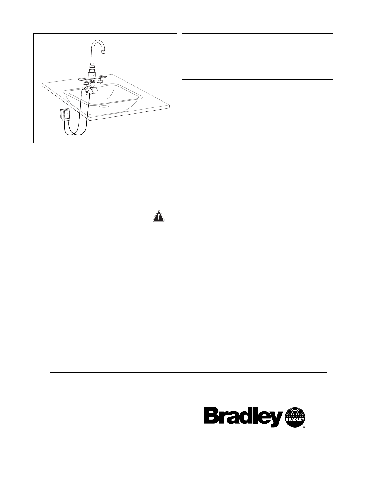
Aerada 1000 Series
Gooseneck Faucet
Installation
Instructions
215-1559 Rev. A; EN 04-216A
© 2004 Bradley Corporation
Page 1 of 8 9/23/04
P.O. Box 309, Menomonee Falls, WI 53052-0309
Phone: 1-800-BRADLEY FAX: (262) 251-5817
http://www.bradleycorp.com
S53-306 DC Gooseneck with Centershank
S53-307 DC Gooseneck with 4" Trimplate
S53-308 AC Gooseneck with Centershank
S53-309 AC Gooseneck with 4" Trimplate
232-007 Plug-In Transformer for AC Gooseneck
Page 2
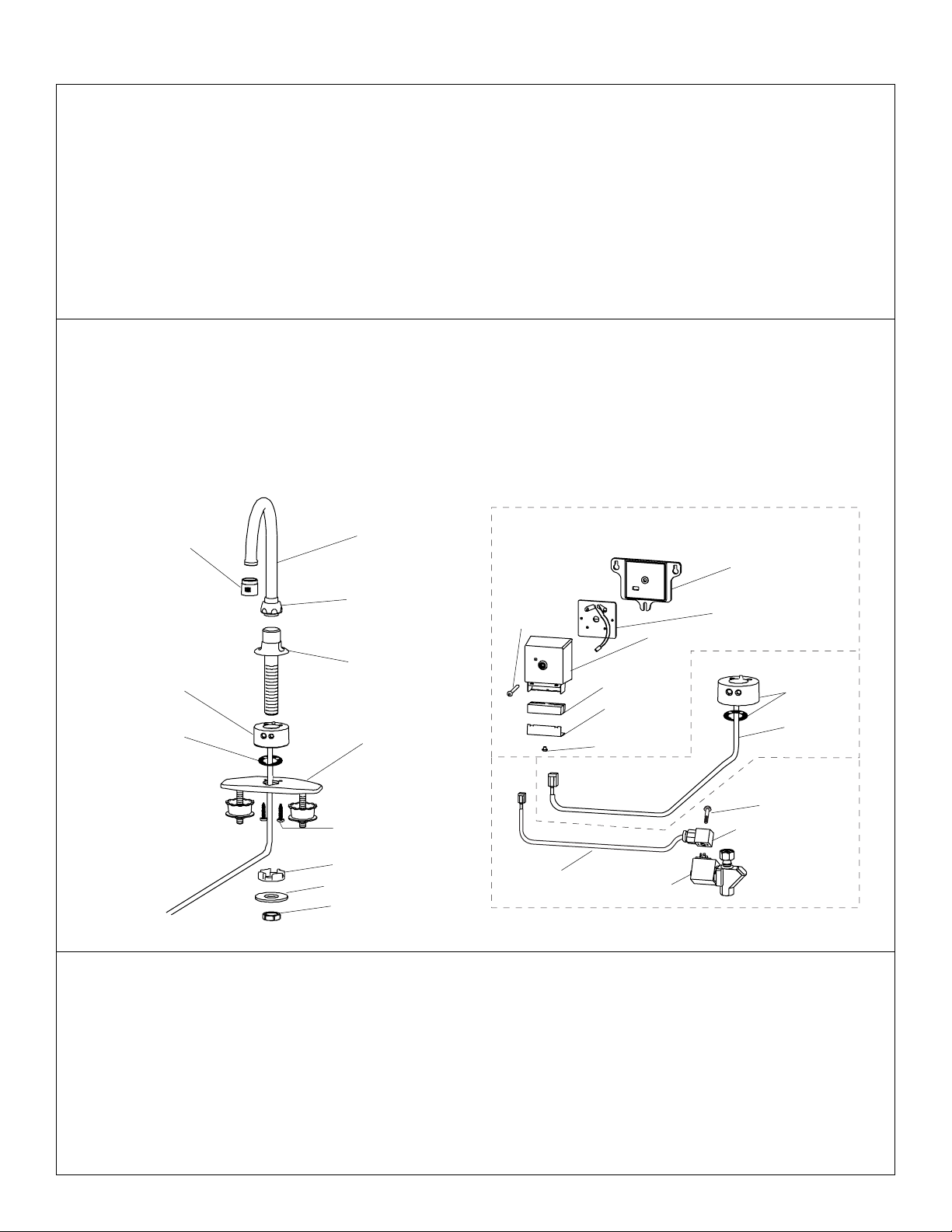
Table of Contents
Faucet Components . . . . . . . . . . . . . . . . . . . . . . . . . . . . . . . . . . . . . . . . .2
Supplies Required for Installation . . . . . . . . . . . . . . . . . . . . . . . . . . . . . .2
Installation Information
Installing Single Hole and Cover Plate . . . . . . . . . . . . . . . . . . . . . . . . 3
Installing Solenoid Valves and Electronic Box (AC) . . . . . . . . . . . . . .4
Installing Electronic Battery Box (DC) . . . . . . . . . . . . . . . . . . . . . . . .5
Maintenance Information
Changing Faucet Operation . . . . . . . . . . . . . . . . . . . . . . . . . . . . . . . . .6
Faucet Troubleshooting . . . . . . . . . . . . . . . . . . . . . . . . . . . . . . . . . . .7–8
Aerada 1000 Series Gooseneck Faucet Installation Instructions
2 9/23/04 Bradley Corporation • 215-1559 Rev. A; EN 04-216A
Supplies Required for Installation:
• Teflon Tape
• Plumber’s Putty (for securing faucet to deck ONLY)
• 1/2" NPT water inlet supply
• Pipe fittings
Components for Aerada 1000 Series Faucet
Carefully separate all parts from packaging and check each part with the illustrations below. Make
sure all parts are accounted for before discarding any packaging material. If any parts are missing,
do not attempt to install your Bradley Faucet until you obtain the missing parts.
1000 Series Faucet (shown w/cover plate)
Spout
Vandal-Resistant
Aerator
(269-1817)
Spout Nut
Spout Shank
4" Cover Plate
(optional)
Sensor Collar
Collar Gasket
Screw
Stilt Washer
Shank Washer
Locking Nut
Electronic Box and Solenoid
Baseplate
Partition Assembly
Electronics Cover
Screw
Screw
Screw
Foam Gasket
Collar &
Gasket
Outer Strain
Relief Bracket
Solenoid
DIN Connector
Cable
(Collar Assembly)
Cable
(Solenoid
Assembly)
269-1809-AC (shown), 269-1810-DC (w/Batteries)
269-1813
269-1808
Page 3
Installation Instructions - Single Hole and Cover Plate
3
Installation Instructions Aerada 1000 Series Gooseneck Faucet
Bradley Corporation • 215-1559 Rev. A; EN 04-216A 9/23/04
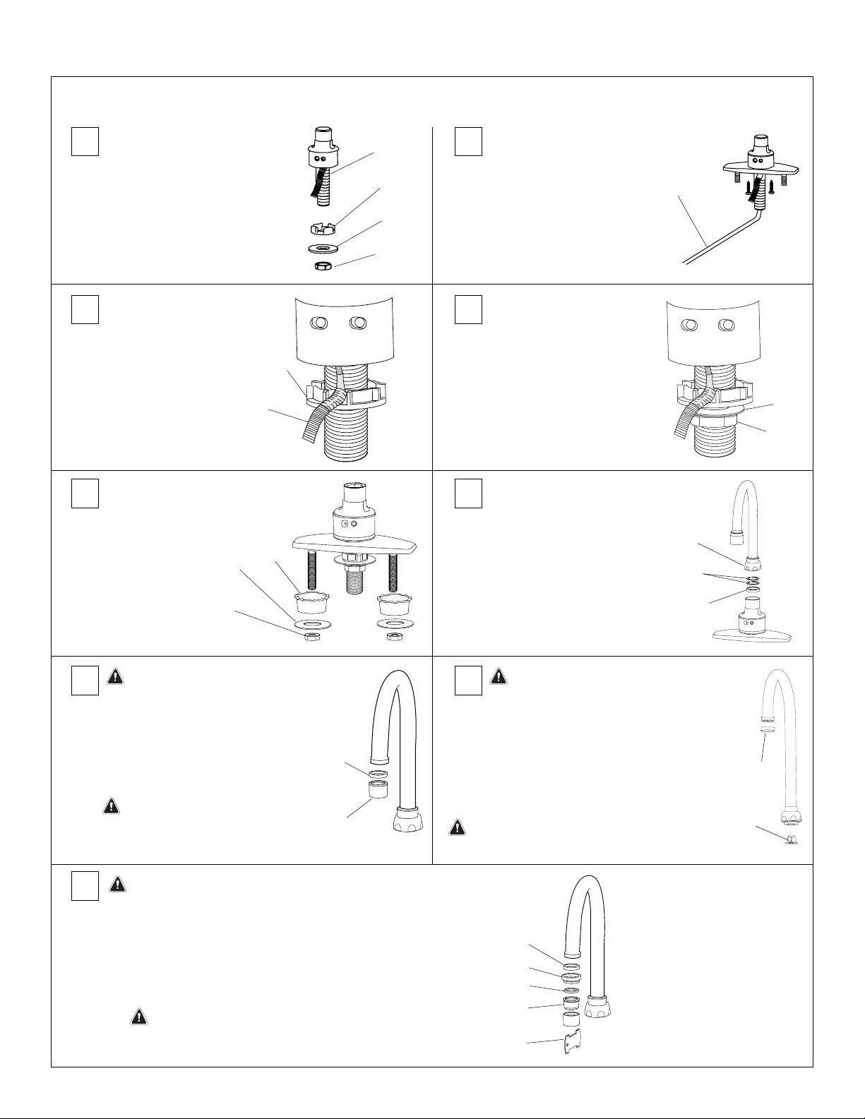
1 2
3 4
7a
5 6
8
Remove the locknut (1), washer
(2), stilt washer (3) from the
spout shank (4). Remove shank
from cover plate (if supplied).
Install stilt washer (1) all
the way up onto shank,
crown side up. Position
sensor cable (2) through
one of the rounded slots
in the stilt washer (1).
If faucet was installed with
cover plate, secure cover plate
with basin washers (1), flat
washers (2) and locknuts (3).
Install the shank washer (1)
and locknut (2) onto faucet
shank. Tighten locknut
securely to prevent collar and
spout from rotating. If
necessary, support spout base
from above to prevent twisting.
Install spout nut (1) onto the
spout.
For swivel mount, only install
two plastic split washers (2).
For rigid mount, only install
1/8" thick plastic washer (3).
Mount the spout completely
into the base and securely
tighten the spout nut (1).
Attach the outlet assembly (1) and aerator
gasket (2) to the spout. The outlet assembly
is equipped from the factory with a 0.5 GPM
cartridge (white screen). To configure the
outlet with the 2.2 GPM cartridge (yellow
screen) refer to step 8.
IMPORTANT: If 0.5 GPM spout is to
be used, skip Step 8 and proceed
directly to
Installation - Solenoid
and Optional Valves, page 4.
To convert outlet assembly to 2.2 GPM:
1. Disassemble outlet assembly using key (1).
2. Remove the 0.5 GPM cartridge (white screen) and replace it with the
2.2 GPM cartridge (2).
3. Install the rubber washer (3), adapter (4) and aerator gasket (5).
IMPORTANT: Proceed directly to
Installation - Solenoid and
Optional Valves, page 4.
Install faucet assembly
into deck hole.
Use plumbers putty
to seal faucet to deck.
4
3
2
3
1
1
1
2
3
4
5
2
2
2
2
1
3
1
1
1
2
Be careful not to
nick or cut the
sensor cable during
installation.
CAUTION: Flush water lines
before beginning this step.
7b
Attach the plain spray ring (1) to the spout. Insert
the laminar flow control insert (2) into the spout.
IMPORTANT: If laminar flow is to be used,
skip Step 8 and proceed directly to
Solenoid and Optional Valves, page 4.
1
(269-1814)
IMPORTANT: Flow rates exceeding the
0.5 GPM maximum limit for public
lavatories set by ASME A112.18.1
negate the UPC certification of this
faucet for public use applications.
For applications requiring laminar
flow without an aerator, refer to the
instructions below.
2
(269-1815)
IMPORTANT: Flow rates exceeding the 0.5 GPM maximum limit
for public lavatories set by ASME A112.18.1 negate the UPC
certification of this faucet for public use applications.
Page 4

Aerada 1000 Series Gooseneck Faucet Installation Instructions
4 9/23/04 Bradley Corporation • 215-1559 Rev. A; EN 04-216A
Installation Instructions - Solenoid Valves and Electronic Box (AC)
Models S53-308 and S53-309
1
Thread the union nut (1) of the solenoid assembly to the
faucet shank (2). Use Teflon tape on the threads to
ensure a leak-free joint. Make sure the solenoid is
positioned for easy access. Tighten the union nut.
1
2
CAUTION:
Do not use pipe
dope on threads.
The solenoid could
become
contaminated and
will void any
warranty.
2
When installing the transformer, make sure the electrical box
is located within 6' of the sink. Install the baseplate and mount
the electronic box to the desired wall location. The baseplate
must be mounted either level with or above the solenoid
valve, and within 12" of the solenoid valve. Make sure the
transformer wires (1) are positioned in the baseplate channel
(2) before mounting the unit.
1
2
NOTE: When
positioning baseplate,
make sure there is
enough room for drip
loops in final
installation. See Note in
step 7.
3
Remove the strain relief
cover and screw (1)
using hex key provided
(2). Remove both foam
gaskets (3). Separate
the foam gaskets at the
perforation.
1
3
2
CAUTION:
Do not attempt to operate multiple
faucets using a single transformer.
4
Insert smaller foam gasket (3) into strain relief. Install
solenoid cable plug (1) into the smaller, telephone-style
jack in the electronic box. Install faucet sensor cable plug
(2) into the larger RJ-45 jack.
1
3
2
5
Insert larger foam gasket (1). Attach strain relief cover (2)
with screw (3) using hex key provided (4).
1
2
4
3
6
CAUTION:
Faucet will automatically calibrate when sensor
cable is connected and power is supplied. DO
NOT place objects in front of collar sensor for
first 30 seconds after power-up.
Feed the wires from the transformer through the baseplate.
Connect the 1/4" spade terminal to the positive (+) terminal
and connect the 3/16" spade terminal to the negative (-)
terminal. Terminals are two different sizes and match
corresponding terminal clips from transformer.
NOTE: The faucet will
automatically calibrate when
sensor cable is connected
and power is supplied.
Refer to step 8.
7
NOTE: To ensure the
electronic box is level
with or above the
solenoid valve, the
cables should create a
drip loop. The
electronic box is
designed with the wire
connectors facing
downward to ensure
proper drip loops.
2
1
Re-attach the electronic box to the baseplate location
using screw(1) and hex key provided (2).
8
CAUTION: DO NOT turn on water supply
until all electrical connections
are made.
Plug the transformer into the applicable electrical receptacle.
Wait at least 30 seconds, then turn on the water supply.
NOTE: When power is initially supplied, the LED on the electronic
box will blink and an audible indicator chirps twice per second
whenever hand presence is detected. This will continue for 8
minutes and then stop.
Proceed to Faucet Operation, page 6.
Page 5

Installation Instructions - Electronic Battery Box (DC)
Models S53-306 and S53-307
CAUTION: Faucet will automatically calibrate when
sensor cable is connected. DO NOT place
objects in front of collar sensor for first 30
seconds after power-up.
5
Installation Instructions Aerada 1000 Series Gooseneck Faucet
Bradley Corporation • 215-1559 Rev. A; EN 04-216A 9/23/04
1
Install the baseplate and mount the electronic box to the
desired wall location. The baseplate must be mounted either
level with or above solenoid valve, and within 12" of the
solenoid valve.
NOTE: When positioning
the baseplate, make sure
there is enough room for
drip loops in the final
installation. Refer to Note
in step 6.
2
Remove the strain relief cover and screw (1) using hex
key provided (2) . Remove foam gasket (3). Separate the
foam gasket at the perforation.
1
3
2
4
Insert larger foam gasket (1). Attach strain relief cover (2)
and screw (3) using hex key provided (4).
1
2
3
4
5
Mount the electronic box to the wall location using
screw(1) and hex key provided (2).
NOTE: To ensure the
electronic box is level
with or above the
solenoid valve, the cables
should create a drip loop
The electronic box is
designed with the wire
connectors facing
downward to ensure
proper drip loops.
1
2
3
Insert smaller foam gasket (3) into the strain relief. Install
solenoid cable plug (1) into the smaller, telephone-style
jack in the transformer. Install faucet sensor cable plug (2)
into the larger RJ-45 jack.
1
2
3
CAUTION: DO NOT turn on water supply until all
electrical connections are made.
6
Turn on the water supply.
NOTE: When power is initially supplied, the LED on the
electronic box will blink and an audible indicator chirps twice per
second whenever hand presence is detected. This will continue
for 8 minutes and then stop.
Proceed to Faucet Operation, page 6.
Page 6

Faucet Operation
Aerada 1000 Series Gooseneck Faucet Installation Instructions
6 9/23/04 Bradley Corporation • 215-1559 Rev. A; EN 04-216A
Changing Faucet Operation
In order to change any faucet option, the DIPswitch must be
used (located inside the electronics cover assembly, see
illustration this page).
Checking/Changing DIPswitch Settings
1. Remove the electronics cover (1) from the baseplate
(2).
2. Lift the partition (3) out to expose the circuit board and
DIPswitch.
3. To change a DIPswitch setting, use a small pointed
object to move the appropriate DIPswitch to ON or
OFF.
Faucet range and mode settings along with their
corresponding DIPswitch settings are outlined in Table 1 and
Table 2
Resetting Faucet Electronics
In order to reset the faucet electronics, a reset button located
inside the electronics cover assembly must be pushed in
(see illustration this page).
To reset faucet electronics:
1. Remove hex screw holding the electronics cover to the
baseplate and remove cover.
2. Lift the partition out to expose the circuit board and
reset button.
3. Make sure there are no objects in front of the collar
sensor, then push the button to reset.
4. Wait 30 seconds for faucet to automatically calibrate to
the environment.
5. Activate water flow by placing your hand in front of the
sensor.
6. Place partition into the electronics cover.
7. Place the electronics cover onto the baseplate and
secure with the hex screw.
NOTE: Resetting the faucet electronics causes loss of virtual
settings and time in use, and will also start the 8-minute
timer where the LED on the electronics box will blink and an
audible indicator chirps twice per second whenever hand
presence is detected.
ON
ON
OFF
OFF
1 2 3 4 5
1 2 3 4 5
MANUAL
RESET
BUTTON
DIPSWITCHES
Electronics Cover Assembly & DIPswitch
Range Short Normal Far Maximum
Switch 1 off on on off
Switch 2 off off on on
Table 1 - Faucet Range
Normal Scrub Meter Water Saver
Modes Mode Mode Mode Mode
Switch 3 off on off off
Switch 4 off off on off
Switch 5 off off off on
Table 2 - Faucet Mode
Operating Modes
• Normal Motion Detecting Mode: water flows within 1/4
second after activating sensor (i.e., putting hands in
front of collar) and continues to stay on as long as
motion is detected. Maximum time is 45 seconds
(factory default setting).
• Scrub Mode: water continues to flow for 60 seconds
(default) after deactivating the sensor (removing
hands).
• Metered Mode: water flows for 10 seconds (default)
from first hand detection.
• Water Saver Mode: water flows for a maximum of
5 seconds starting from first hand detection and
immediately turns off when hands are removed.
Additional Operating Features
• 12-second, no-motion turn off in normal mode
• “Low battery” indication
• Battery life up to one year depending on frequency
of use.
3
1
2
Page 7

7
Installation Instructions Aerada 1000 Series Gooseneck Faucet
Bradley Corporation • 215-1559 Rev. A; EN 04-216A 9/23/04
Troubleshooting
Whenever new batteries are installed, AC power is applied,
or a manual reset button is pressed, the LED on the
electronics cover will blink and an audible indicator chirps
twice per second whenever hand presence is detected.
After 8 minutes, the LED and buzzer function stops.
If an error occurs, the LED will blink and the buzzer will
sound every 30 seconds to assist in diagnosing the
problem. When corrective action is taken the LED and
buzzer will stop.
The following chart provides details concerning the number
of beeps and possible errors associated with them .
1 Beep: Indicates low battery.
2 Beeps: Calibration out of range (environment too
reflective).
3 Beeps: Room infrared level out of range; too much
sunlight, heat lamp present, etc.
4 Beeps: Solenoid short circuit.
5 Beeps: Solenoid unplugged or loose/broken solenoid
connection.
Refer to Troubleshooting Chart below and on page 8 for
further troubleshooting information.
Disassemble solenoid and inspect/clean parts.
Reduce pressure to under 80 PSI.
Change range setting using DIPswitch (page 6).
Turn on water supply.
Check connection.
Replace electronics cover.
Check connection.
Inspect collar wiring for signs of damage or corrosion.
Replace if necessary.
Replace cover assembly.
Reduce pressure to under 80 PSI.
Replace batteries (DC only).
Use correctly sized terminal clips (page 4).
Faucets must be wired in parallel from transformer
(transformer to each individual unit), not connected in
a series.
Remove interference; reset electronics using reset
button (page 6). Allow 30 seconds for faucet to
automatically re-calibrate.
Change range setting using DIPswitch (page 6).
Change range setting using DIPswitch (page 6).
Water runs continuously.
Faucet turns on by itself
(ghosting).
No water flow.
Debris in solenoid (no beeps).
Water pressure too high (no beeps).
Incorrect range setting for spout type and
sink used (2 beeps).
Water not turned on (no beeps).
Solenoid cable not connected to
electronics cover (5 beeps).
Solenoid short circuit (4 beeps).
Sensor cable not connected to electronics
cover (no beeps).
Inoperative sensor (no beeps).
Inoperative electronics cover assembly
(no beeps).
Water pressure too high (no beeps).
Low battery voltage (DC only) (1 beep).
6VDC transformer not properly connected
to partition assembly (no beeps).
Wiring of multiple unit 6VDC transformer
(no beeps).
Interference during automatic calibration
(no beeps).
Incorrect range setting for type of spout
and sink used.
Lighting environment affecting sensor
(3 beeps).
Problem Check Possible Solution
Range too short or too long.
Page 8

Aerada 1000 Series Gooseneck Faucet Installation Instructions
8 9/23/04 Bradley Corporation • 215-1559 Rev. A; EN 04-216A
Replace solenoid.
Change mode or range setting using DIPswitch (page 6).
Clean internal parts or replace solenoid valve.
Clean outlet.
Change mode setting using DIPswitch (page 6).
Electronics cover must be mounted to allow for drip loops
for the sensor and solenoid cables (pages 4 & 5).
Clean connector.
Reset electronics using reset button (page 6).
Clogged strainer. Clean if necessary.
Clean faucet outlet.
Replace batteries if below 4.2 volts.
Change range setting using DIPswitch (page 6).
Faucet works in reverse.
Faucet turns off too soon.
Faucet stays on longer than
normal.
Faucet stopped working.
Solenoid wiring on DIN connector
(no beeps).
Faucet operating mode (no beeps) or
faucet range setting.
Dirty solenoid valve (no beeps).
Clogged spout outlet.
Faucet in wrong mode (no beeps).
Mounting of electronics cover (no beeps).
Sensor cable connector.
No clicking sound from solenoid during
hand presence (no beeps).
Solenoid valve strainer.
Check if faucet outlet is clogged
(no beeps).
Battery voltage (battery operated only).
Incorrect range setting for spout type and
sink used (no beeps).
Problem Check Possible Solution
Troubleshooting
continued . . .
 Loading...