

Page 1
P.O. Box 309, Menomonee Falls, WI USA 53052-0309
PHONE 1-800-BRADLEY FAX (262) 251-5817
http://www.bradleycorp.com
Installation
215-533 Rev. U; EN 06-532G
© 2007 Bradley Corporation
Page 1 of 13 6/26/07
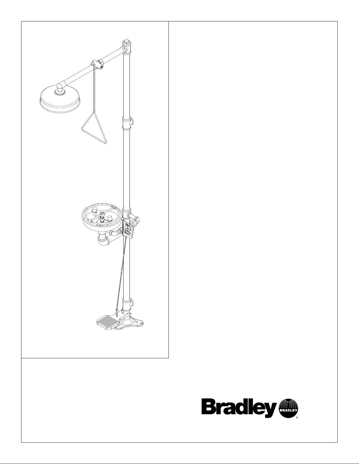
S19-310SS
Combination Drench Shower/Eyewash
Combiné douche/lave-yeux
Combinación de ducha de
aspersión/lavaojos
Table of Contents
Pre-Installation Information . . . . . . . . . . . . . . . . . .2
Installation Instructions . . . . . . . . . . . . . . . . . . . . . .3
Assembly of Components . . . . . . . . . . . . . . . . . . . .4
Parts List . . . . . . . . . . . . . . . . . . . . . . . . . . . . . . . . .5
Table des matières
Avant l’installation . . . . . . . . . . . . . . . . . . . . . . . . .6
Instructions d’installation . . . . . . . . . . . . . . . . . . . .7
Montage . . . . . . . . . . . . . . . . . . . . . . . . . . . . . . . . . .8
Liste des pièces . . . . . . . . . . . . . . . . . . . . . . . . . . . .9
Contenido
Información previa a la instalación . . . . . . . . . . . .10
Instrucciones de instalación . . . . . . . . . . . . . . . . . .11
Montaje de los componentes . . . . . . . . . . . . . . . . .12
Lista de piezas . . . . . . . . . . . . . . . . . . . . . . . . . . . .13
Page 2
2
S19-310SS Installation
6/26/07 Bradley Corporation • 215-533 Rev. U; EN 06-532G
WARNING
Read this installation manual completely to ensure proper installation, then file it
with the owner or maintenance department. Compliance and conformity to drain
requirements and other local codes and ordinances is the responsibility of the
installer.
Separate parts from packaging and make sure all parts are accounted for before
discarding any packaging material. If any parts are missing, do not begin
installation until you obtain the missing parts.
Flush the water supply lines before beginning installation and after installation is
complete. Test the unit for leaks and adequate water flow. Main water supply to
the eyewash should be “ON” at all times. Provisions shall be made to prevent
unauthorized shutoff.
The ANSI Z358.1 standard requires an uninterruptible supply of flushing fluid at a
minimum 30 PSI (0.21 MPa) flowing pressure. Flushing fluid should be tepid per
ANSI Z358.1.
The inspection and testing results of this equipment should be recorded weekly
to verify proper operation. This equipment should be inspected annually to
ensure compliance with ANSI Z358.1.
Workers who may come in contact with potentially hazardous materials should be
trained regarding the placement and proper operation of emergency equipment
per ANSI Z358.1.
For questions regarding the operation or installation of this product, visit
www.bradleycorp.com or call 1-800-BRADLEY.
Product warranties may also be found under ”Product Information” on our web
site at www.bradleycorp.com.
Installation
T
H
IS
S
ID
E
U
P
Packing List
!
!
!
!
P
.O
. B
o
x
3
0
9
, M
e
n
o
m
o
n
e
e
F
a
lls
, W
I 5
3
0
5
1
R
T
E
S
T
T
H
I
S
U
N
I
T
E
A
C
H
W
E
E
K
Test-operate valve(s) each week and sign below
.
R
eport any m
alfunctions imm
ediately.
Ven
til(e) w
öche
ntlich im
Testbe
trieb prüfen
, bestätig
t
durch U
ntersch
rift. Jeg
liche Störung sofort m
eld
en.
Date
Datum
Date
Signed
Unterschrift
Signe
Date
Date
Date Signed
Signed
Signed
D
I
E
S
E
S
G
E
R
Ä
T
1
S
T
W
Ö
C
H
E
N
T
L
I
C
H
Z
U
P
R
Ü
F
E
N
.
E
S
S
A
I
H
E
B
D
O
M
A
D
A
I
R
E
Test le fonctionnem
ent des va
lves chaque se
m
ain
e et
signe en bas. S
'il y à quelque chose q
u
i ne va pas fait
un rapport im
médiatem
ent.
P.O. BOX 309, MENOMONEE FALLS, WI 53052-0309 USA
TEL: 1-800-BRADLEY FAX: (262-251-5817)
http://www.bradleycorp.com
114-051
Page 3
3
Installation S19-310SS
Bradley Corporation • 215-533 Rev. U; EN 06-532G 6/26/07
Installation Instructions
Supplies Required:
• (3) 3/8" floor anchors and bolts
• Piping to 1-1/4" BSP water supply inlet
• Adequate supply pipe supports
• Piping to 1-1/4" IPS drain outlet on unit
• Minimum 4" drain to accommodate 30 gallons
per minute discharge for drench shower waste
• OPTIONAL: sign mounting hardware
Step 1: Secure base to floor
1. Install three suitable anchors (by installer)
for 3/8" bolts in the floor (see Figure 1).
2. Bolt the base to the floor anchors using 3/8"
bolts (supplied by installer).
Step 2: Assemble eyewash components
1. Assemble the remaining unit components as
shown in Figure 2 on page 4.
• Apply pipe sealant or tape (supplied by
installer) to all male-threaded pipe joints.
• Use rubber grip pad or strap wrench around
pipes when tightening to prevent marring.
Place grip pad on pipe and then put wrench
over grip pad. With grip pad in place, turn
pipe with wrench.
• The bottom edge of the showerhead should
be 7'-1" (2160mm) from floor.
2. When connecting steel chain, first connect
chain to foot treadle “S” hook. Then with
foot treadle raised up, straighten chain and
connect a link to “S” hook on valve handle.
Make sure steel chain is pulled tight. The
length of chain used will vary.
IMPORTANT: Do not rely on Bradley’s
Combination Unit to support supply
piping.
Step 3: Connect water supply
1. Connect water supply piping to 1-1/4" IPS inlet on unit (piping supplied by installer). Provide
adequate supports (supplied by installer) for supply pipe using pipe hangers or other means.
2. Connect drain piping to 1-1/4" IPS drain outlet on unit (piping supplied by installer).
3. Hang the safety sign from the unit with the curtain hooks provided (or mount it to the wall using
sign-mounting hardware supplied by installer).
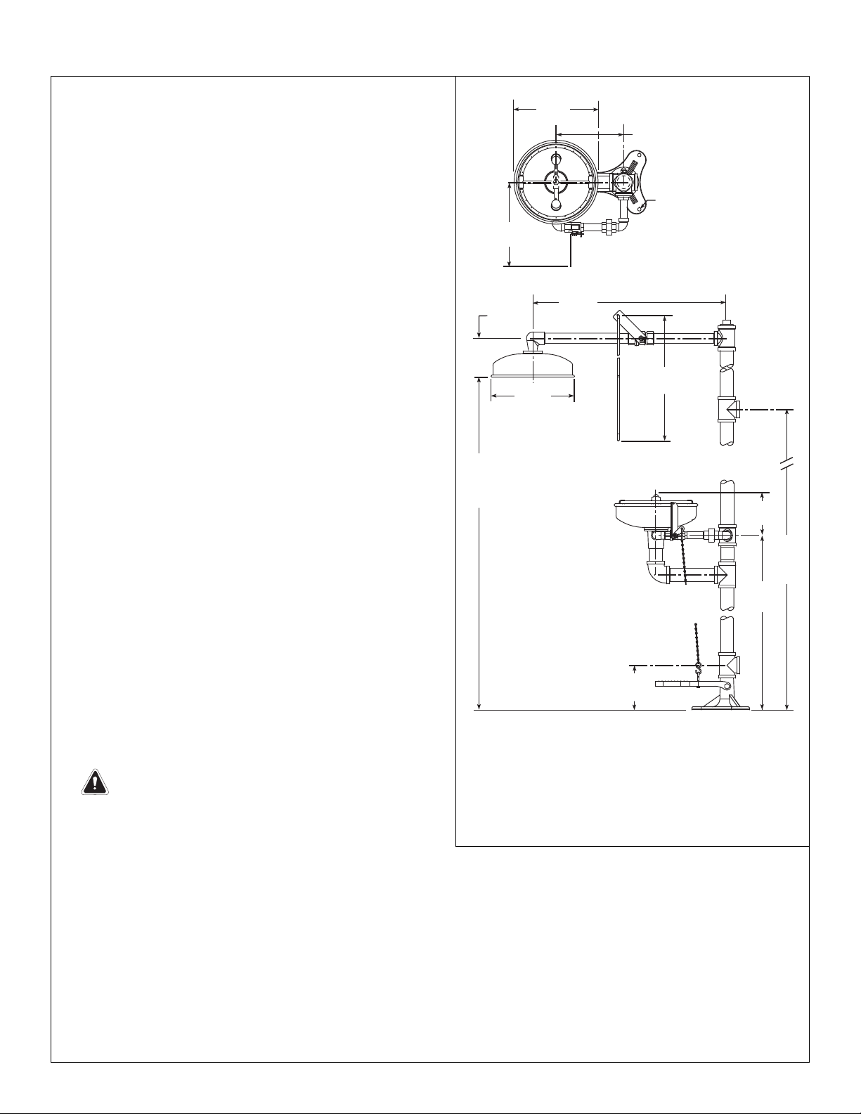
Figure 1
NOTE: All dimensions assume standard thread
engagement. Variations in manufacturing allow
for +/- 1/8" (3mm) per threaded joint. To find
the tolerance of a dimension, add the number
of thread joints in between a dimension and
multiply it by 1/8" (3mm).
Ø10-3/4"
(273mm)
9" (229mm)
10-1/2"
(266mm)
9" (229mm) DIA. FLANGE
WITH (3) 3/8"DIA. HOLES
ON AN 8" (203mm)
DIA. BOLT CIRCLE
5-1/8"
(130mm)
26-3/8"
(670mm)
Ø10-3/4"
(273mm)
24"
(610mm)
7'-1"
(2160mm)
TO
FLOOR
6"
(152mm)
6"
(152mm)
66"
(1676mm)
TO
FLOOR
36-3/8"
(924mm)
Page 4
4
S19-310SS Installation
6/26/07 Bradley Corporation • 215-533 Rev. U; EN 06-532G
Assembly of Components
P.O. Box 309, Menomonee Falls, WI 53051
R
TEST THIS UNIT EACH WEEK
Test-operate valve(s) each week and sign below.
Report any malfunctions immediately.
Ventil(e) wöchentlich im Testbetrieb prüfen, bestätigt
durch Unterschrift. Jegliche Störung sofort melden.
Date
Datum
Date
Signed
Unterschrift
Signe
Date
Date
Date
Signed
Signed
Signed
DIESES GERÄT 1ST WÖCHENTLICH ZU PRÜFEN.
ESSAI HEBDOMADAIRE
Test le fonctionnement des valves chaque semaine et
signe en bas. S'il y à quelque chose qui ne va pas fait
un rapport immédiatement.
P.O. BOX 309, MENOMONEE FALLS, WI 53052-0309 USA
TEL: 1-800-BRADLEY FAX: (262-251-5817)
http://www.bradleycorp.com
114-052
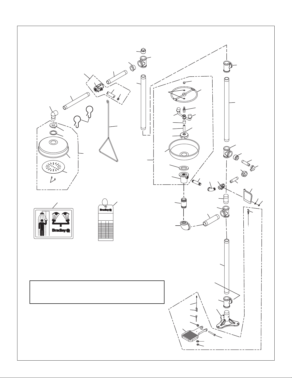
NOTE: Items 10.1–10.2 come preassembled as Item 10.
Items 13.1–13.5 come preassembled as Item 13.
Items 25.1–25.12 come preassembled as Item 25.
Figure 2
12
13.5
13.2
13.1
11
13.3
13.4
6
7
9
9.1
8
3
9.2
9.11
NOTE: If Tee is used as a
supply inlet, use plug in Item 2
2
ALTERNATE 1-1/4" IPS
SUPPLY INLET
25.12
25.10
25.11
2
1-1/4" IPS
Supply Inlet
5
25.9
25.8
FLOW
CONTROL
THIS
END
10
14
25.7
25.6
25.5
25.4
2
13
25.3
25
25.2
15
16
17
18
25.1
22
17
20
16
21
27
P.O. Box 309, Menomonee Falls, WI 53051
TEST THIS UNIT EACH WEEK
DIESES GERÄT 1ST WÖCHENTLICH ZU PRÜFEN.
ESSAI HEBDOMADAIRE
Test-operate valve(s) each week and sign below.
Report any malfunctions immediately.
Ventil(e) wöchentlich im Testbetrieb prüfen, bestätigt
durch Unterschrift. Jegliche Störung sofort melden.
Test le fonctionnement des valves chaque semaine et
signe en bas. S'il y à quelque chose qui ne va pas fait
un rapport immédiatement.
Date
Signed
Datum
Unterschrift
Date
Signe
P.O. BOX 309, MENOMONEE FALLS, WI 53052-0309 USA
TEL: 1-800-BRADLEY FAX: (262-251-5817)
http://www.bradleycorp.com
114-052
28
R
Date
Signed
Date
Signed
Date
Signed
24
23
26.3
26.2
26.1
26.6
26.5
19
1-1/4" IPS
Drain Outlet
4
30
20.1
2
26.1
3
2
1
26.7
26.4
26.8
Page 5

5
Installation S19-310SS
Bradley Corporation • 215-533 Rev. U; EN 06-532G 6/26/07
Parts List
1 131-062 1 Base
2 269-237 5 Pipe Tee 1-1/4" IPS
3 113-583 2 Pipe 1-1/4" IPS x 22-1/2"
4 S06-188 1 Plugged Nipple
5 113-584 1 Pipe 1-1/4" IPS x 26-1/2"
6 269-238 1 Pipe Plug 1-1/4" IPS
7 269-236 1 Reduc’g Bushing 1-1/4" to 1" IPS
8 113-006NX 1 Pipe 1" IPS x 9"
9 S30-061 1 Stay-Open Ball Valve 1" IPS
9.1 S27-276 1 1" Ball Valve with Jam Nut
9.11 161-079 1 Jam Nut only
9.2 128-142 1 Handle
10 151-001 2 Curtain Hook
11 113-006MN 1 Pipe 1" IPS x 12"
12 169-854 1 90º Street Elbow 1" IPS
13 S24-113 1 Showerhead Assembly
13.1 125-001DP 1 Rubber Washer
13.2 153-235 1 Adapter
13.3 187-053 1 Showerhead Shell
13.4 155-008 1 Diffuser
13.5 160-410 2 Shoulder Screw
14 128-156A 1 Pull Rod - 24" Long
15 269-239 1 Reduc’g Bushing 1-1/4" to 1" IPS
16 113-965 2 Pipe 1/2" IPS x 3-3/8"
17 269-241 2 Elbow
18 269-240 1 Union 1/2" IPS
19 113-582 1 Pipe 1-1/4" IPS x 6-1/2"
20 S27-287 1 1/2" Ball Valve with Jam Nut
20.1 161-151 1 Jam Nut only
21 S08-338 1 Handle Assembly
22 113-866 1 Pipe 1/2" IPS x 4"
23 269-242 1 90° Pipe Elbow 1-1/4" IPS
24 113-579 1 Pipe Nipple 1-1/4" IPS x 3
25 S90-317 1 Stainless Steel Spray Ring Assy.
25.1 111-049 1 Inlet-Drain Fitting
25.2 124-028 1 Center Seal Gasket
25.3 187-053 1 Stainless Steel Bowl
25.4 173-009 1 Cup Strainer
25.5 S21-074 1 Supply Pipe
25.6 113-1159 1 Spacer, Drain
25.7 S05-131 1 Eyewash Yoke
25.8 107-371 2 Dust Cover
25.9 269-912 1 Swivel Stem
25.10 124-055 2 Quad Ring
25.11 S57-148 1 Spray Ring Assembly
25.12 110-209 1 Acorn Nut
26 S45-1314SS 1 HFSO Prepack
26.1 269-646 2 “S” Hook
26.2 134-009A 1 Stainless Steel Chain
26.3 181-008SS 1 Treadle
26.4 160-401 1 Screw
26.5 161-137 1 Nut, Acorn
26.6 147-026 1 Eye Bolt
26.7 142-002BT 1 Lockwasher
26.8 161-025 1 Hex Nut
27 114-052 1 Safety Sign
28 204-421 1 Emergency Tag
29 269-915 1 Grip Pad (not shown)
30 142-002DA 1 Washer
Item Part No. Qty Description
Item Part No. Qty Description
Prepack S45-1788 includes Items 25.9, 25.10, 25.11, 25.12
Page 6

6
S19-310SS Installation
6/26/07 Bradley Corporation • 215-533 Rev. U; EN 06-532G
AVERTISSEMENT
Lire ce manuel d'installation dans son intégralité pour garantir une installation
appropriée. Une fois celle-ci terminée, classer ce manuel auprès du service à la
clientèle ou d'entretien. L'installateur est responsable de la conformité de
l'installation aux codes pour des drain et codes et règlements en vigueur.
Assurez-vous que toutes les pièces sont incluses dans l’emballage et qu’il n’en
manque aucune avant de jeter l’emballage. Ne commencez pas l’assemblage
avant de recevoir les pièces manquantes.
Rincez la conduite d’alimentation avant et apres l’installation. Assurez-vous que
le débit d’eau est adéquat et qu’il n’y a pas de fuites. L’alimentation principale en
eau doit être toujours OUVERTE. On devra prévoir des dispositions pour
empêcher tout arrêt non autorisé.
La norme ANSI Z358.1 requiert une alimentation sans coupure du liquide de
rinçage à une pression minimum de 30 psi (0.21 MPa). Le liquide de rinçage doit
être tiède conformément à la norme ANSI Z358.1.
Inspectez et testez cet équipement une fois par semaine pour en assurer le bon
fonctionement. Notez les dates d’inspection. Ce matériel doit être inspecté une
fois par an pour assurer sa conformité à la norme ANSI Z358.1.
Les ouvriers susceptibles d'entrer en contact avec des matières potentiellement
dangereuses doivent recevoir une formation sur la mise en place et le bon
fonctionnement du matériel d'urgence conformément à la norme ANSI Z358.1.
Pour toute question concernant le fonctionnement ou l'installation de ce produit,
consulter le site www.bradleycorp.com ou appeler le 1-800-BRADLEY.
Les garanties de produits figurent sous la rubrique « Informations techniques »
sur notre site Internet à www.bradleycorp.com.
Installation
T
H
IS
S
I
D
E
U
P
Packing List
!
!
!
!
P
.O
. B
o
x
3
0
9
, M
e
n
o
m
o
n
e
e
F
a
lls
, W
I 5
3
0
5
1
R
T
E
S
T
T
H
I
S
U
N
I
T
E
A
C
H
W
E
E
K
Test-operate valve(s) each week and sign below
.
R
eport an
y m
alfunctions imm
ediately.
V
entil(e) w
öchentlich im T
estbetrieb prüfen, bestätigt
durc
h U
nterschrift. Jegliche Störung so
fort m
eld
en.
Date
Datum
Date
Signed
Unterschrift
Signe
Date
Date
Date Signed
Signed
Signed
D
I
E
S
E
S
G
E
R
Ä
T
1
S
T
W
Ö
C
H
E
N
T
L
I
C
H
Z
U
P
R
Ü
F
E
N
.
E
S
S
A
I
H
E
B
D
O
M
A
D
A
I
R
E
Test le fonctionnem
ent des valves ch
aque sem
aine et
signe en bas. S'il y à quelque chose q
ui n
e va pas fait
un rapport im
médiatement.
P.O. BOX 309, MENOMONEE FALLS, WI 53052-0309 USA
TEL: 1-800-BRADLEY FAX: (262-251-5817)
http://www.bradleycorp.com
114-051
Page 7

7
Installation S19-310SS
Bradley Corporation • 215-533 Rev. U; EN 06-532G 6/26/07
Instructions d’installation
Fournitures :
•
3 ancrages au sol et boulons de 3/8"
• Produit d’étanchéité pour tuyaux
• Tuyau d’alimentation pour branchement au raccord IPS
de 1-1/4" d’arrivée d’eau de l’appareil
• Supports adéquats pour la tuyauterie d’alimentation
• Tuyau de vidange de 1-1/4" IPS pour la douche oculaire
• Un renvoi de 4" minimum pour la douche d'urgence
assurant une capacité de vidange de 30 gal/mn (115 l/mn)
• Quincaillerie pour l'installation de l'enseigne
Étape 1: Fixation de la base au sol
1. Poser dans le sol trois chevilles (à fournir) pour
les trois vis de 3/8 in. (Figure 1).
2. Viser la base dans le sol avec trois vis de 3/8 in.
(à fournir).
Étape 2: Montage
1. Monter le reste des éléments comme sur les
Figure 2 aux page 8.
• Appliquer de la pâte ou du ruban d’étanchéité
(à fournir) sur tous les filetages mâles.
• Utiliser un isolant en caoutchouc ou une clé à
sangle pour ne pas rayer les tuyaux lors du
serrage. Placer un isolant sur le tuyau puis la
clé sur l’isolant . Une fois l’isolant en place,
tourner le tuyau avec la clé.
• Le bord inférieur du pommeau de la douche
d’urgence doit se trouver à
7'-1" (2160mm)
du sol.
2. Pour raccorder la chaîne d’acier, la poser d’abord
sur le «S» de la pédale. Ensuite, relever la
pédale, tendre la chaîne et accrocher un de ses
maillons au crochet en «S» situé sur le levier de
la vanne. Veiller à ce que la chaîne soit tendue.
La longueur de la chaîne est variable.
IMPORTANT: Ne pas utiliser la douche
comme support de la tuyauterie.
Étape 3: Raccordement de
l’alimentation en eau
1. Brancher l’alimentation en eau sur l’orifice d’alimentation de 1-1/4 in. IPS de la douche d’urgence
(tuyauterie à fournir). Prévoir des supports adéquats (à fournir) pour la tuyauterie d’alimentation.
2. Brancher l’alimentation en eau sur l’orifice d’évacuation de 1-1/4 in. IPS de la douche d’urgence
(tuyauterie à fournir).
3. Accrochez l'enseigne de sécurité avec les crochets fournis (ou fixer sur le mur ou sur la tuyauterie avec la
visserie non fournie).
Figure 1
7'-1"
(2160mm)
au
sol
66"
(1676mm)
au
sol
Bride 9" (229mm) avec (3)
trous de 3/8" (10mm) sur
un cercle 8" (203mm).
NOTE:
Toutes les dimensions supposent un engagement
de filetage standard. Les variations de fabrication
prévoient +/- 3,1 mm (1/8") par joint fileté. Pour
trouver la tolérance d'une dimension, ajouter le
nombre de joints filetés entre une dimension et le
multiplier par 3,1 mm (1/8").
10-1/2"
(266mm)
5-1/8"
(130mm)
7'-1"
(2160mm)
TO
FLOOR
Ø10-3/4"
(273mm)
9" (229mm)
9" (229mm) DIA. FLANGE
WITH (3) 3/8"DIA. HOLES
ON AN 8" (203mm)
DIA. BOLT CIRCLE
26-3/8"
(670mm)
24"
Ø10-3/4"
(273mm)
(610mm)
6"
(152mm)
36-3/8"
(924mm)
6"
(152mm)
66"
(1676mm)
TO
FLOOR
Page 8

Assemblage des composantes
P.O. Box 309, Menomonee Falls, WI 53051
R
TEST THIS UNIT EACH WEEK
Test-operate valve(s) each week and sign below.
Report any malfunctions immediately.
Ventil(e) wöchentlich im Testbetrieb prüfen, bestätigt
durch Unterschrift. Jegliche Störung sofort melden.
Date
Datum
Date
Signed
Unterschrift
Signe
Date
Date
Date
Signed
Signed
Signed
DIESES GERÄT 1ST WÖCHENTLICH ZU PRÜFEN.
ESSAI HEBDOMADAIRE
Test le fonctionnement des valves chaque semaine et
signe en bas. S'il y à quelque chose qui ne va pas fait
un rapport immédiatement.
P.O. BOX 309, MENOMONEE FALLS, WI 53052-0309 USA
TEL: 1-800-BRADLEY FAX: (262-251-5817)
http://www.bradleycorp.com
114-052
Figure 2
8
S19-310SS Installation
6/26/07 Bradley Corporation • 215-533 Rev. U; EN 06-532G
Figure 2
2
Alimentation
1-1/4 " IPS
Orifice de vidange
1-1/4 " IPS
2
Alimentation
1-1/4 " IPS
NOTE: Si le raccord en té est
utilisé comme orifice d'admission,
utiliser le bouchon au point nº 2.
NOTE: Les pièces 10.1–10.2 sont livrées
montées sous le n° 10.
Les pièces 13.1–13.5 sont livrées
montées sous le n° 13.
Les pièces 25.1–25.12 sont livrées
montées sous le n° 25.
Contrôle
du débit,
ce bout
6
7
9
9.1
11
12
10
13.2
13.1
13
13.3
13.4
13.5
8
3
9.2
9.11
14
25
NOTE: If Tee is used as a
supply inlet, use plug in Item 2
2
ALTERNATE 1-1/4" IPS
SUPPLY INLET
25.12
25.11
25.10
25.9
25.7
25.6
25.5
25.4
25.8
FLOW
CONTROL
THIS
END
25.3
25.2
25.1
22
17
20
2
1-1/4" IPS
Supply Inlet
5
2
15
16
18
16
21
17
27
R
P.O. Box 309, Menomonee Falls, WI 53051
TEST THIS UNIT EACH WEEK
DIESES GERÄT 1ST WÖCHENTLICH ZU PRÜFEN.
ESSAI HEBDOMADAIRE
Test-operate valve(s) each week and sign below.
Report any malfunctions immediately.
Ventil(e) wöchentlich im Testbetrieb prüfen, bestätigt
durch Unterschrift. Jegliche Störung sofort melden.
Test le fonctionnement des valves chaque semaine et
signe en bas. S'il y à quelque chose qui ne va pas fait
un rapport immédiatement.
Date
Signed
Date
Signed
Datum
Unterschrift
Date
Signed
Date
Signe
Date
Signed
P.O. BOX 309, MENOMONEE FALLS, WI 53052-0309 USA
TEL: 1-800-BRADLEY FAX: (262-251-5817)
http://www.bradleycorp.com
114-052
28
24
23
26.2
26.1
26.6
26.5
26.3
19
1-1/4" IPS
Drain Outlet
4
30
20.1
2
26.1
3
2
1
26.7
26.4
26.8
Page 9

Liste des pièces
9
Installation S19-310SS
Bradley Corporation • 215-533 Rev. U; EN 06-532G 6/26/07
1 131-062 1 Bride
2 269-237 5 Té 1-1/4" IPS
3 113-583 2 Tuyau 1-1/4" IPS x 22-1/2"
4 S06-188 1 Mamelon obturé
5 113-584 1 Tuyau 1-1/4" IPS x 26-1/2"
6 269-238 1 Bouchon 1-1/4" IPS
7 269-236 1 Réducteur 1-1/4" > 1" IPS
8 113-006NX 1 Tuyau 1" IPS x 9"
9 S30-061 1 Robinet de 1" à tournant sphérique
fermé/ouvert
9.1 S27-276 1 Robinet 1po (avec écrou)
9.11 161-079 1 Écrou (seulement)
9.2 128-142 1 Manette
10 151-001 2 Crochet
11 113-006MN 1 Tuyau 1" IPS x 12"
12 169-854 1 Coude 90° de 1" IPS
13 S24-113 1 Tête de douche
13.1 125-001DP 1 Rondelle de caoutchouc
13.2 153-235 1 Adaptateur
13.3 187-053 1 Coquille
13.4 155-008 1 Diffuseur
13.5 160-410 2 Vis
14 128-156A 1 Tige - 24"
15 269-239 1 Réducteur 1-1/4" > 1/2" IPS
16 113-965 2 Tuyau 1/2" IPS x 3-3/8"
17 269-241 2 Coude
18 269-240 1 Union 1/2" IPS
19 113-582 1 Tuyau 1-1/4" IPS x 6-1/2"
20 S27-287 1 Robinet 1/2 po (avec écrou)
20.1 161-151 1 Écrou (seulement)
21 S08-338 1 Assemblage de manette
22 113-866 1 Tuyau 1/2" IPS x 4"
23 269-242 1 Coude 90° 1-1/4" IPS
24 113-579 1 Raccord 1-1/4" IPS x 3"
25 S90-317 1 Disperseur Annulaire
25.1 111-049 1 Raccordement d’entrée du drain
25.2 124-028 1 Joint d’etanchéité
25.3 187-053 1 Assemblage du récepteur inox
25.4 173-009 1 Filtre à tamis
25.5 S21-074 1 Alimentation acier inox
25.6 113-1159 1 Entretoise
25.7 S05-131 1 Assemblage de cadre
25.8 107-371 2 Couvercle anti-poussières
25.9 269-912 1 Pivot
25.10 124-055 2 Rondelle
25.11 S57-148 1 Diffuseur Annulaire
25.12 110-209 1 Écrou Borgne
26 S45-1314SS 1 HFSO Préemballé
26.1 269-646 2 Crochet en S
26.2 134-009A 1 Chaîne en acier inoxydable
26.3 181-008SS 1 Pédale
26.4 160-401 1 Vis
26.5 161-137 1 Écrou
26.6 147-026 1 Boulon à œil
26.7 142-002BT 1 Rondelle de blocage
26.8 161-025 1 Écrou hexagonal
27 114-052 1 Enseigne de sécurité
28 204-421 1 Etiquette d’inspection
29 269-915 1 Tampon anti dérapant (non montré)
30 142-002DA 1 Rondelle
Piéce Réf Qté Description
Piéce Réf Qté Description
Paquet S45-1788 comprend les éléments 25.9, 25.10, 25.11, 25.12
Page 10

10
S19-310SS Installation
6/26/07 Bradley Corporation • 215-533 Rev. U; EN 06-532G
ADVERTENCIA
Lea en su totalidad este manual de instalación para garantizar una instalación
adecuada. Una vez que termine la instalación, entregue este manual al propietario o
al Departamento de Mantenimiento. Es responsabilidad de quien instale el equipo
cumplir con los códigos para desagüe y otra códigos y ordenanzas locales.
Separar todas las piezas del material de embalaje y asegurarse que todas las piezas
estén incluídas antes de desechar cualquier material de embalaje. Si faltase alguna
pieza, no intentar instalar la unidad combinada Bradley hasta obtener las piezas
faltantes.
Aclarar el conducto del suministro de agua antes y después de la instalación.
Verificar que no haya fugas y que el flujo de agua sea adecuado. El suministro
principal de agua a la unidad debe estar siempre en posición “ON” (abierto). Se
deben tomar medidas a fin de evitar el corte no autorizado del suministro.
La norma ANSI Z358.1 exige un suministro ininterrumpido del líquido de enjuague a
una presión mínima de 30 psi
(0.21 MPa). El líquido de limpieza debe estar tibio en
conformidad con la norma ANSI Z358.1.
Este equipo se debe inspeccionar, probar y anotar semanalmente para mantener un
funcionamiento adecuado
. Se debe revisar este equipo anualmente para asegurarse
de que cumpla con la norma ANSI Z358.1.
Los trabajadores que puedan tener contacto con materiales potencialmente
peligrosos deben recibir capacitación sobre la ubicación y operación adecuada de
los equipos de emergencia en conformidad con la norma ANSI Z358.1.
Para consultas sobre la operación o instalación de este producto, visite
www.bradleycorp.com o llame al 1-800-BRADLEY.
Las garantías del producto se pueden encontrar en "Información del producto" o en
nuestro sitio Web, www.bradleycorp.com.
Installation
T
H
IS
S
I
D
E
U
P
Packing List
!
!
!
!
P
.O
.
B
o
x
3
0
9
, M
e
n
o
m
o
n
e
e
F
a
ll
s
, W
I 5
3
0
5
1
R
T
E
S
T
T
H
I
S
U
N
I
T
E
A
C
H
W
E
E
K
Test-operate
valve(s) ea
c
h w
eek an
d sign b
elo
w.
R
epo
rt any
m
alfu
ncti
ons im
m
ediately.
V
en
til(e) wöc
hentlic
h im
T
estbetrieb
p
rü
fen, be
stätig
t
durch Un
tersc
hrift. Jegliche S
törun
g sofo
rt m
elden
.
Date
Datum
Date
Signed
Unterschrift
Signe
Date
Date
Date Signed
Signed
Signed
D
I
E
S
E
S
G
E
R
Ä
T
1
S
T
W
Ö
C
H
E
N
T
L
I
C
H
Z
U
P
R
Ü
F
E
N
.
E
S
S
A
I
H
E
B
D
O
M
A
D
A
I
R
E
Test le fonc
tio
nnem
ent des valve
s ch
aqu
e sem
aine
et
s
ig
ne en b
as. S
'il y
à quelque cho
se qu
i n
e va pas fait
un rap
port im
mé
diatem
en
t.
P.O. BOX 309, MENOMONEE FALLS, WI 53052-0309 USA
TEL: 1-800-BRADLEY FAX: (262-251-5817)
http://www.bradleycorp.com
114-051
Page 11

11
Installation S19-310SS
Bradley Corporation • 215-533 Rev. U; EN 06-532G 6/26/07
Instrucciones de instalación
Materiales necesarios:
•
(3) Pernos y anclajes para piso de 3/8"
• Tubo al tubo de entrada de abastecimiento de agua
BSP de 1-1/4" en la unidad
• Soportes adecuados para los tubos de abastecimiento
• Tubo a salida de drenaje IPS de 1-1/4"
• Drenaje mínimo de 4" (102mm) para acomodar una
descarga de 30 galones (115 litros) por minuto para el
consumo de la ducha de aspersión
• Torniller
ía para montar el aviso de seguridad
Paso 1: Afianzar la base al piso
1. Instalar los tres anclajes apropiados
(suministrados por el instalador) para los pernos
de 3/8" en el piso (ver la figura 1).
2. Empernar la base a los anclajes de piso utilizando
pernos de 3/8" (suministrados por el instalador).
Paso 2: Montar los componentes
1. Montar el resto de los componentes de la unidad
como se muestra en las figura 2 en las página 12.
• Aplicar obturador de tubo o cinta (suministrado
por el instalador) a todas las juntas de tuberías
con rosca macho.
• Utilizar un taco de sujeción o llave de correa
alrededor de los tubos al apretar para evitar
arañazos. Colocar el taco de sujeción sobre el
tubo y, a continuación, la llave de tuercas sobre
el taco de sujeción. Con el taco de sujeción en su
lugar, hacer girar el tubo con la llave de tuercas.
• El borde inferior del cabezal de ducha debe
estar a 7'-1" (2160mm) del piso.
2. Al conectar una cadena de acero, conectar
primero la cadena al gancho en “S” del pedal.
Luego, con el pedal levantado, enderezar la
cadena y conectar un eslabón al gancho en “S” de
la manilla de la válvula. Asegurarse de que la
cadena de acero esté tirante. La longitud de la
cadena utilizada variará.
IMPORTANTE: No depender de la unidad
combinada de Bradley para soportar el tubo
de abastecimiento.
Paso 3: Conectar el abastecimiento de agua
1. Conectar el tubo de abastecimiento e agua al tubo de entrada IPS de 1-1/4" en la unidad (tubo suministrado
por el instalador). Proveer soportes adecuados (suministrados por el instalador) para los tubos de
abastecimiento utilizando cuelgatubos u otros medios.
2. Conectar el tubo (suministrado por el instalador) de drenaje a la salida de drenaje IPS de 1-1/4" en la unidad.
3. Cuelgue la señal de seguridad con los ganchos suministrada (o montar la señal de seguridad en la pared o en
el tubo utilizando la tornillería de montaje de señal suministrada por el instalador).
Figura 1
7'-1"
(2160mm)
AL
PISO
66"
(1676mm)
AL
PISO
Brida de 9" (229mm) de
dia. con (3) 3/8" (10mm)
de dia. en un circulo de
perno de 8" (203mm) de
dia.
NOTA:
Todas las dimensiones asumen el enganche de
rosca estándar. Las variaciones en la fabricación
permiten +/- 3,1 mm (1/8") por junta roscada. Para
encontrar la tolerancia de una dimensión,
agregue el número de juntas roscadas entre una
dimensión y multiplíquelo por 3,1 mm (1/8").
10-1/2"
(266mm)
5-1/8"
(130mm)
7'-1"
(2160mm)
TO
FLOOR
Ø10-3/4"
(273mm)
9" (229mm)
9" (229mm) DIA. FLANGE
WITH (3) 3/8"DIA. HOLES
ON AN 8" (203mm)
DIA. BOLT CIRCLE
26-3/8"
(670mm)
24"
Ø10-3/4"
(273mm)
(610mm)
6"
(152mm)
36-3/8"
(924mm)
6"
(152mm)
66"
(1676mm)
TO
FLOOR
Page 12

Armado de los componentes
P.O. Box 309, Menomonee Falls, WI 53051
R
TEST THIS UNIT EACH WEEK
Test-operate valve(s) each week and sign below.
Report any malfunctions immediately.
Ventil(e) wöchentlich im Testbetrieb prüfen, bestätigt
durch Unterschrift. Jegliche Störung sofort melden.
Date
Datum
Date
Signed
Unterschrift
Signe
Date
Date
Date
Signed
Signed
Signed
DIESES GERÄT 1ST WÖCHENTLICH ZU PRÜFEN.
ESSAI HEBDOMADAIRE
Test le fonctionnement des valves chaque semaine et
signe en bas. S'il y à quelque chose qui ne va pas fait
un rapport immédiatement.
P.O. BOX 309, MENOMONEE FALLS, WI 53052-0309 USA
TEL: 1-800-BRADLEY FAX: (262-251-5817)
http://www.bradleycorp.com
114-052
Figure 2
12
S19-310SS Installation
6/26/07 Bradley Corporation • 215-533 Rev. U; EN 06-532G
Figura 2
SALIDA DE
DRENADO
(1-1/4 IPS)
2
ENTRADA DE
SUMINISTRO
(1-1/4" IPS)
NOTA: Los artículos del 10.1–10.2 vienen previamente
montados como Artículo 10.
Los artículos del 13.1–13.5 vienen previamente
montados como Artículo 13.
Los artículos del 25.1–25.12 vienen previamente
montados como Artículo 25.
2
ENTRADA DE
SUMINISTRO
(1-1/4" IPS)
NOTA: Si el acoplamiento en
T se usa como entrada,
utilizar el tapón artículo Nº 2.
Control
del flujo
en este
extremo
6
7
9
9.1
11
12
10
13.2
13.1
13
13.3
13.4
13.5
8
3
9.2
9.11
14
NOTE: If Tee is used as a
supply inlet, use plug in Item 2
2
ALTERNATE 1-1/4" IPS
SUPPLY INLET
25.10
25.7
25.6
25.5
25.4
25.3
25
25.2
25.1
25.12
25.11
25.9
25.8
FLOW
CONTROL
THIS
END
22
17
20
2
1-1/4" IPS
Supply Inlet
5
2
15
16
18
16
21
17
27
P.O. Box 309, Menomonee Falls, WI 53051
TEST THIS UNIT EACH WEEK
DIESES GERÄT 1ST WÖCHENTLICH ZU PRÜFEN.
ESSAI HEBDOMADAIRE
Test-operate valve(s) each week and sign below.
Report any malfunctions immediately.
Ventil(e) wöchentlich im Testbetrieb prüfen, bestätigt
durch Unterschrift. Jegliche Störung sofort melden.
Test le fonctionnement des valves chaque semaine et
signe en bas. S'il y à quelque chose qui ne va pas fait
un rapport immédiatement.
Date
Signed
Datum
Unterschrift
Date
Signe
P.O. BOX 309, MENOMONEE FALLS, WI 53052-0309 USA
TEL: 1-800-BRADLEY FAX: (262-251-5817)
http://www.bradleycorp.com
114-052
28
R
Date
Signed
Date
Signed
Date
Signed
24
23
26.3
26.2
26.1
26.6
26.5
19
1-1/4" IPS
Drain Outlet
4
30
20.1
2
26.1
3
2
1
26.7
26.4
26.8
Page 13

13
Installation S19-310SS
Bradley Corporation • 215-533 Rev. U; EN 06-532G 6/26/07
Lista de piezas
1 131-062 1 Base
2 269-237 5 Tubo en T IPS de 1-1/4"
3 113-583 1 Tubo IPS de 1-1/4" x 22-1/2"
4 S06-188 1 Tubo de empalme de rosca macho
5 113-584 1 Tubo IPS de 1-1/4" x 26-1/2"
6 269-238 1 Tapón 1-1/4" IPS
7 269-236 1 Casq Red.1-1/4" de 1" IPS
8 113-006NX 1 Tubo IPS de 1" x 9"
9 S30-061 1 Válvula de flotador de abertura
continua IPS de 1"
9.1 S27-276 1 Válvula de flotador de 1" (con tuerca)
9.11 161-079 1 Tuerca (solamente)
9.2 128-142 1 Manija
10 151-001 2 Gancho
11 113-006MN 1 Tubo IPS de 1" x 12"
12 169-854 1 Codo IPS de rosca macho y hembra
de 90°de 1"
13 S24-113 1 Conjunto de cabezal rociador
13.1 125-001DP 1 Rondana
13.2 153-235 1 Adaptador
13.3 187-053 1 Receptor de lavado de los ojos
13.4 155-008 1 Difusor
13.5 160-410 2 Tornillo
14 128-156A 1 Varilla de tiro 24" de largo
15 269-239 1 Casq Red.1-1/4" de 1/2" IPS
16 113-965 2 Tubo IPS de 1/2" x 3-3/8"
17 269-241 2 Codo
18 269-240 1 Unión 1/2" IPS
19 113-582 1 Tubo IPS de 1-1/4" x 6-1/2"
20 S27-287 1 Válvula de bola de 1/2" (con tuerca)
20.1 161-151 1 Tuerca (solamente)
21 S08-338 1 Conjunto de la manilla
22 113-866 1 Tubo 1/2" IPS x 4"
23 269-242 1 Codo tubo 90° IPS de 1-1/4"
24 113-579 1 Empalme 1-1/4" IPS x 3"
25 S90-317 1 Conj. de aros de rociado inox
25.1 111-049 1 Conex. de entrada de desagüe
25.2 124-028 1 Junta del sello central
25.3 187-053 1 Receptor de lavado de los ojos de
acero inoxidable
25.4 173-009 1 Coladera
25.5 S21-074 1 Conjunto del tubo de abastecimiento
25.6 113-1159 1 Espaciador
25.7 S05-131 1 Conj. de la horq del lavaojos
25.8 107-371 2 Cubiertas contra el polvo con ligaduras
26 S45-1314SS 1 Preempaquetado de HFSO
26.1 269-646 2 Gancho en "S"
26.2 134-009A 1 Cadena de acero inoxidable
26.3 181-008SS 1 Pedal
26.4 160-401 1 Tornillo
26.5 161-137 1 Tuerca
26.6 147-026 1 Perno de ojo
26.7 142-002BT 1 Rondana de seguridad
26.8 161-025 1 Tuerca hexagonal
27 114-052 1 Letero de seguridad
28 204-421 1 Etiqueta de emergencia
29 269-915 1 Taco de sujeción (no se muestra)
30 142-002DA 1 Rondana
Art. Pieza No. Cant. Descripción
Art. Pieza No. Cant. Descripción
Paquete S45-1788 incluye art. 25.9, 25.10, 25.11, 25.12
 Loading...