

Page 1
Installation
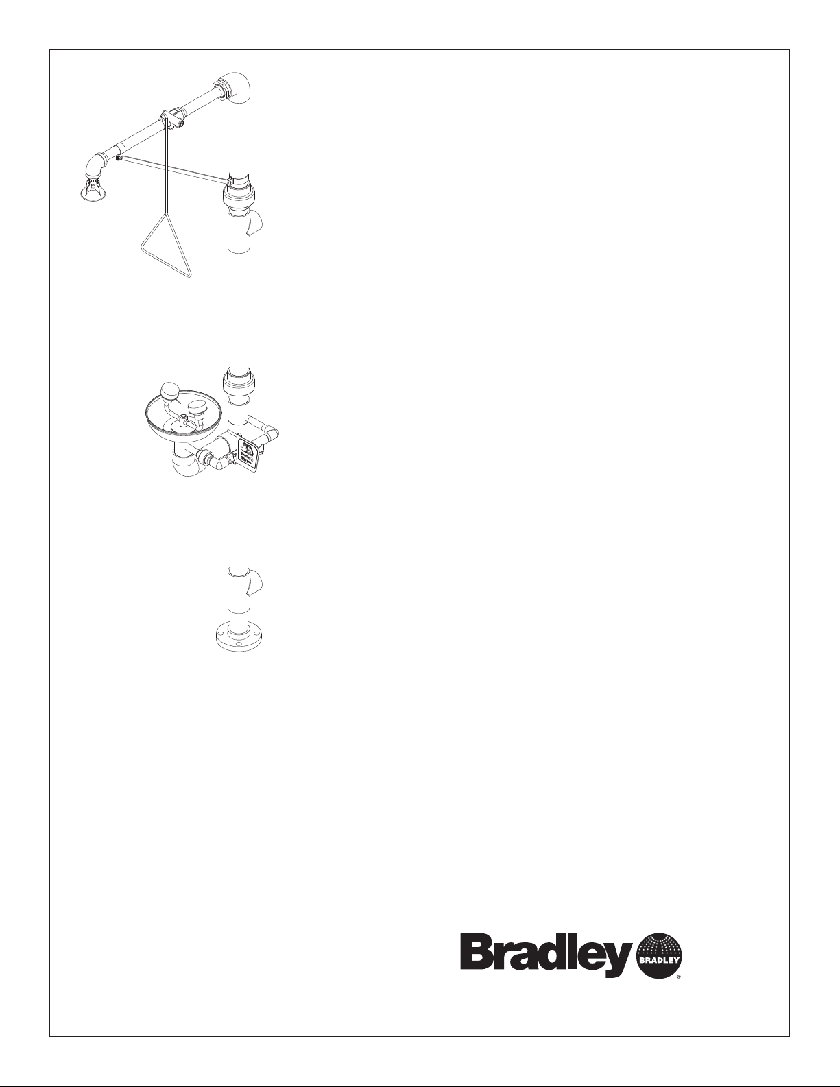
S19-310PVC
Combination Drench Shower and
Eye/Face Wash
Combiné douche oculaire/faciale
Combinación de ducha de
aspersión y lavador de ojos/rostro
Table of Contents
Pre-Installation Information . . . . . . . . . . . . . . 2
Installation Instructions. . . . . . . . . . . . . . . . . . 3
Assembly of Components . . . . . . . . . . . . . . . 4
Parts List . . . . . . . . . . . . . . . . . . . . . . . . . . . . 5
Table des matières
Avant l’installation. . . . . . . . . . . . . . . . . . . . . . 6
Instructions d’installation . . . . . . . . . . . . . . . . 7
Assemblage des composantes . . . . . . . . . . . 8
Liste des pièces . . . . . . . . . . . . . . . . . . . . . . . 9
Contenido
Información previa a la instalación. . . . . . . . 10
Instrucciones de instalación. . . . . . . . . . . . . 11
Armado de los componentes . . . . . . . . . . . . 12
Lista de piezas . . . . . . . . . . . . . . . . . . . . . . . 13
215-1134 Rev. T; ECM 09-05-0019
© 2009 Bradley Corporation
Page 1 of 13 8/11/09
P.O. Box 309, Menomonee Falls, WI USA 53052-0309
PHONE 800.BRADLEY (800.272.3539) FAX 262.251.5817
bradleycorp.com
Page 2
S19-310PVC Installation
IMPORTANT
Installation
R
1
5
0
3
I 5
W
,
s
ll
a
F
e
e
n
o
R
P
m
o
U
n
Z
e
H
M
,
IC
9
L
0
K
T
3
E
N
E
x
E
eek an
o
H
W
C
B
H
.
Ö
h w
C
O
c
E
.
W
A
P
R
I
T
E
s immed
S
A
T
I
D
1
Testbe
N
A
T
e(s) ea
U
Ä
M
R
S
O
I
alv
h im
E
D
H
eglic
T
B
G
alfunction
tlic
E
S
T
E
S
H
I
S
E
y m
hen
T
A
E
hrift. J
I
perate v
S
D
öc
S
E
nnem
'il y
ntersc
Test-o
eport an
m
R
as. S
fonctio
Ventil(e) w
t im
durch U
e en b
Test le
rappor
sign
un
Date
Datum
Date
114-051
.
N
E
F
Ü
belo
d sign
.
y
el
prüfen,
iat
b
g s
trie
törun
es
he S
alv
e c
es v
ent d
ent.
à quelqu
édiatem
Signed
Unterschrift
Signe
.
w
ätigt
est
elden.
b
aine et
t m
as fait
or
a p
of
e v
chaque sem
se qui n
ho
Date
Date
Date
P.O. BOX 309, MENOMONEE FALLS, WI 53052-0309 USA
TEL: 1-800-BRADLEY FAX: (262-251-5817)
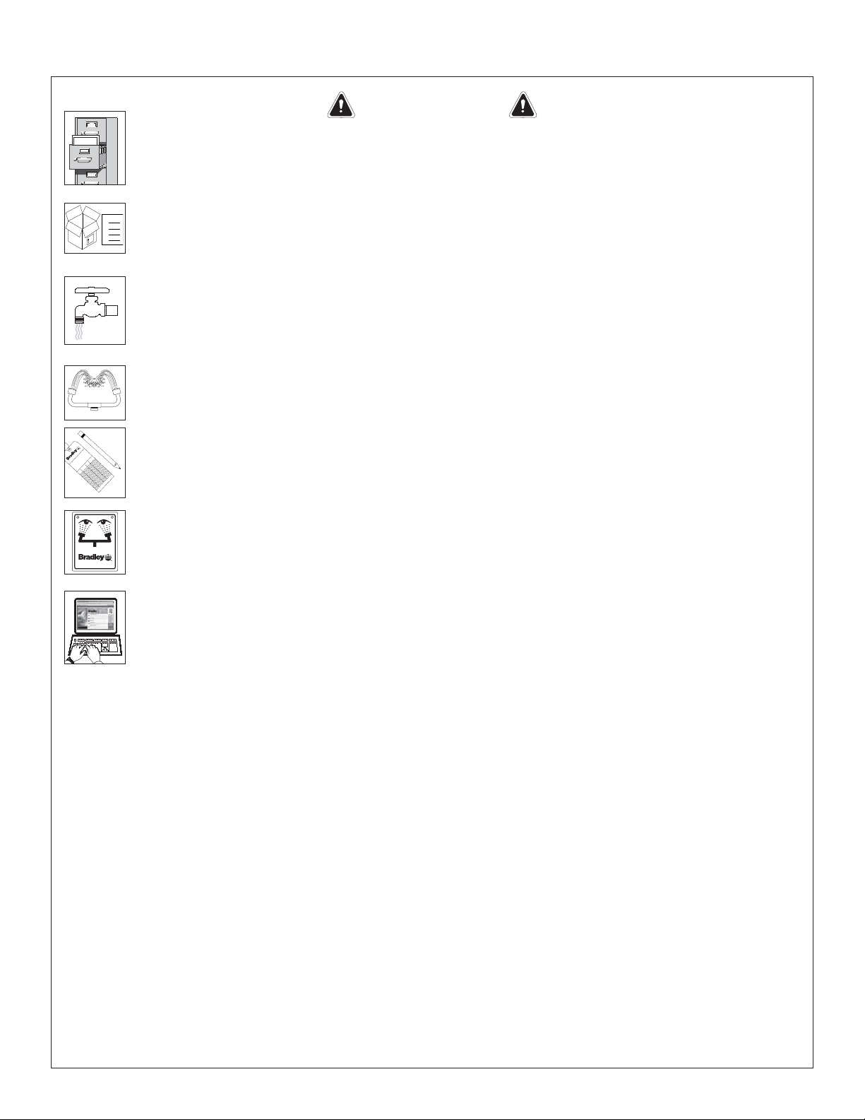
Read this installation manual completely to ensure proper installation, then file it
with the owner or maintenance department. Compliance and conformity to drain
requirements and other local codes and ordinances is the responsibility of the installer.
Separate parts from packaging and make sure all parts are accounted for before
Packing List
•
•
•
THIS
SIDE
UP
discarding any packaging material. If any parts are missing, do not begin installation
•
until you obtain the missing parts.
Flush the water supply lines before beginning installation and after installation is
complete. Test the unit for leaks and adequate water flow. Main water supply to the
eyewash should be “ON” at all times. Provisions shall be made to prevent unauthorized
shutoff.
The ANSI Z358.1 standard requires an uninterruptible supply of flushing fluid at a
minimum 30 PSI (0.21 MPa) flowing pressure. Flushing fluid should be tepid per ANSI
Z358.1.
Signed
Signed
Signed
The inspection and testing results of this equipment should be recorded weekly to verify
proper operation. This equipment should be inspected annually to ensure compliance
with ANSI Z358.1.
Workers who may come in contact with potentially hazardous materials should be
trained regarding the placement and proper operation of emergency equipment per ANSI
http://www.bradleycorp.com
Z358.1.
For questions regarding the operation or installation of this product, visit www.
bradleycorp.com or call 1-800-BRADLEY.
Product warranties and service parts information may also be found under ”Products”
on our web site at www.bradleycorp.com.
2
8/11/09 Bradley Corporation • 215-1134 Rev. T; ECM 09-05-0019
Page 3
Installation S19-310PVC
Installation
3
⁄8"
Supplies Required:
• (4) 5⁄8" floor anchors and bolts
• PVC compatible pipe sealant and teflon tape
• Piping to 2" PVC water supply inlet on unit
• Piping to 2" PVC drain outlet for eye wash on unit
• Adequate supply pipe supports
• Minimum 4" (102mm) drain to accommodate 30 gallons
per minute discharge for drench shower waste
• OPTIONAL: sign-mounting hardware
NOTE: Local codes may require the installation
of a backfl ow prevention valve to complete proper
installation. Compliance with local codes is the
responsibility of the installer. Valve must be tested
annually to verify that it is functioning properly. Backfl ow
prevention valves are not included with the fi xture and
may be supplied by the contractor or purchased from
Bradley Corporation.
IMPORTANT: Do not rely on Bradley’s
Combination Unit to support supply piping.
Step 1: Assemble and Install Drench Shower
1. Install four suitable anchors (supplied by installer)
for 5/8” bolts in the floor.
2. Bolt the base to the floor anchors using
(supplied by installer).
3. Assemble the remaining drench shower
components as shown on page 4.
• Apply PVC compatible pipe sealant or teflon
tape (by installer) to all male-threaded pipe
joints.
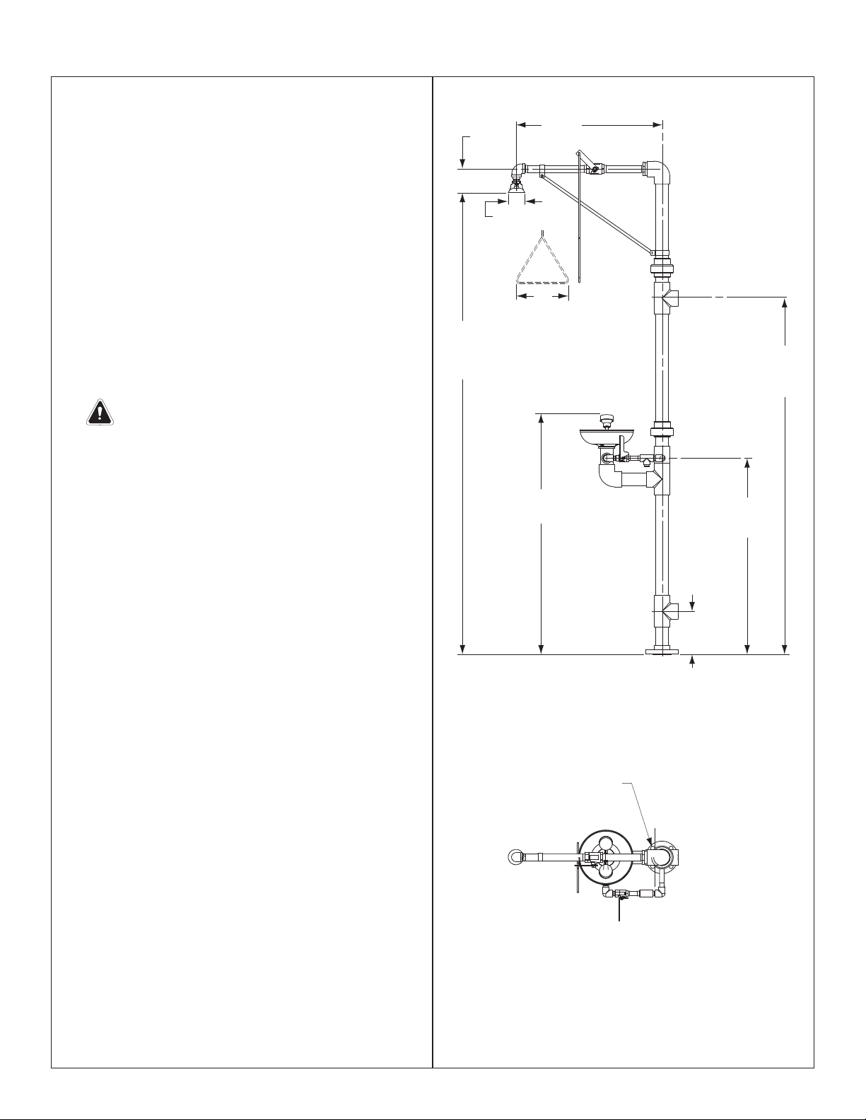
• The bottom edge of the showerhead should be
84" (2134mm) from the floor.
4. Connect the water supply piping to the 2" PVC
inlet on the unit (piping by installer). Provide
adequate supports (supplied by installer) for
supply pipe using pipe hangers or other means.
5. Connect the drain piping to the 2" PVC drain
outlet on the unit (piping supplied by installer).
5
⁄8" bolts
4½"
(114mm)
Ø 3.1"
(78.7mm)
84"
(2134mm)
to fl oor
26
(670mm)
9"
(229mm)
433⁄8"
(1100mm)
66"
(1676mm)
to fl oor
36"
(914mm)
8"
(203mm)
Step 2: Assemble and Install Eye/Face Wash
NOTE: See pages 4–5 for part identifi cation.
1. While holding the elbow in the lower assembly
piping, thread pipe #113-946 (Item #21) through
the hole in the lower assembly piping, and connect
(4) Ø ¾" (19mm)
Holes on Ø 4¾"
(121mm) Bolt Circle
to the elbow.
2. Install the reducer on top of the elbow.
3. Center the elbow, then tighten the pipe #113-946
(Item #21) in place.
4. Install the union and pipe nipple on pipe #113-946
(Item #21).
5. Place the gasket, then the strainer, on top of the
lower assembly piping.
6. Place the eyewash bowl on top of the strainer.
7. Install the yoke assembly by connecting the
stainless steel pipe, at the base of the yoke
assembly, to the reducer on the elbow.
8. Connect the pipe nipple to the valve piping
NOTE: All dimensions assume standard thread
engagement. Variations in manufacturing allow for
+/- 1⁄8" (3mm) per threaded joint. To fi nd the tolerance
of a dimension, add the number of thread joints in
between a dimension and multiply it by 1⁄8" (3mm).
assembly.
Bradley Corporation • 215-1134 Rev. T; ECM 09-05-0019 8/11/09
3
Page 4
S19-310PVC Installation
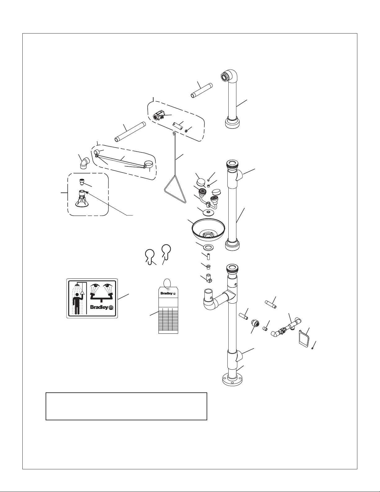
Assembly of Components
10
11
7
7.1
7.2
3
7.11
6
5.1
6.3
6.4, 6.5
6.1
6.2
NOTE: Use
teflon tape
16
4
2" PVC
Supply Inlet
29
27
13
12
17
25
2
8
5
only.
24
26
23
18
22
P.O. BOX 309, MENOMONEE FALLS, WI 53052-0309 USA
TEL: 1-800-BRADLEY FAX: (262-251-5817)
http://www.bradleycorp.com
30
114-052
9
P.O. Box 309, Menomonee Falls, WI 53051
TEST THIS UNIT EACH WEEK
DIESES GERÄT 1ST WÖCHENTLICH ZU PRÜFEN.
ESSAI HEBDOMADAIRE
Test-operate valve(s) each week and sign below.
Report any malfunctions immediately.
Ventil(e) wöchentlich im Testbetrieb prüfen, bestätigt
durch Unterschrift. Jegliche Störung sofort melden.
Test le fonctionnement des valves chaque semaine et
signe en bas. S'il y à quelque chose qui ne va pas fait
un rapport immédiatement.
Date
Signed
Date Signed
Datum
Unterschrift
Date
Date
Signe
Date
R
Signed
Signed
NOTE: Seal all male threads with PVC compatible pipe
sealant or teflon tape. Assemble couplings handtight; then tighten one full turn with a wrench.
21
20
2" PVC
Drain Outlet
1
28
14
19
15
14.1
4
8/11/09 Bradley Corporation • 215-1134 Rev. T; ECM 09-05-0019
Page 5

Installation S19-310PVC
Parts List
Item Part No. Qty Description
1 S90-337 1 PVC Lower Assembly
2 S90-338 1 PVC Middle Assembly
3 S90-339 1 PVC Upper Assembly
4 128-156A 1 Pull Rod - 24" Long
5 S24-188 1 Plastic Showerhead Assy.
5.1 S24-187 1 Flow control Assembly, 23 GPM
6 S90-341 1 2" x 1" Pipe Hanger Assembly
6.1 269-1121 1 ½" Support Rod
6.2 269-1123 1 1" Pipe Hanger
6.3 269-1124 1 2" Pipe Hanger
6.4 160-069 2 Screw
6.5 161-047 2 Hex Nut
7 S30-061 1 1" Ball Valve Assembly
7.1 S27-276 1 1" Ball Valve with Nut
7.11 161-079 1 Jam Nut only
7.2 128-142 1 Handle
Item Part No. Qty Description
13 269-874 1 Cap Plug - Eye/Face Wash
14 S90-008 1 Valve Piping Assembly with Nut
14.1 110-215 1 Jam Nut only
15 S08-338 1 Handle
16 154-058 1 Plastic Eyewash Receptor
17 S05-131 1 Eye Wash Yoke Sub-Assembly
18 151-001 2 Curtain Hook
19 113-936 1 PVC Pipe Nipple
20 269-1114 1 PVC Union
21 113-946 1 PVC Pipe Nipple Modified
22 269-1120 1 PVC 90° Elbow
23 269-1119 1 PVC Reducer
24 124-028 1 Gasket
25 173-025 1 Cup Strainer
26 113-1151 1 Supply Pipe
27 S53-063 2 Tethered Dust Cover
8 269-1109 1 1" PVC 90° Elbow
9 113-942 1 1" PVC Pipe x Closed Nipple
10 113-944 1 1" PVC Pipe x 8" Long
11 113-945 1 1" PVC Pipe x 12" Long
12 153-333 1 Pipe Plug
Item 6.2 includes items 6.4, 6.5
Item 6.3 includes items 6.4, 6.5
28 113-940 1 ½" Pipe Nipple
29 S05-135 2 EFW Assembly
30 114-052 1 Safety Sign
31 204-421 1 Emergency Inspection Tag
Bradley Corporation • 215-1134 Rev. T; ECM 09-05-0019 8/11/09
5
Page 6

S19-310PVC Installation
IMPORTANT
Lire ce manuel d’installation dans son intégralité pour garantir une installation
Installation
THIS
SIDE
UP
appropriée. Une fois celle-ci terminée, classer ce manuel auprès du service à la clientèle
ou d’entretien. L’installateur est responsable de la conformité de l’installation aux codes
pour des drain et codes et règlements en vigueur.
Assurez-vous que toutes les pièces sont incluses dans l’emballage et qu’il n’en manque
Packing List
•
•
•
aucune avant de jeter l’emballage. Ne commencez pas l’assemblage avant de recevoir
•
les pièces manquantes.
Rincez la conduite d’alimentation avant et apres l’installation. Assurez-vous que le débit
d’eau est adéquat et qu’il n’y a pas de fuites. L’alimentation principale en eau doit être
toujours OUVERTE. On devra prévoir des dispositions pour empêcher tout arrêt non
autorisé.
La norme ANSI Z358.1 requiert une alimentation sans coupure du liquide de rinçage
à une pression minimum de 30 psi (0.21 MPa). Le liquide de rinçage doit être tiède
conformément à la norme ANSI Z358.1.
R
1
5
0
3
I 5
W
,
s
ll
a
.
.
N
F
e
E
w
e
F
n
Ü
.
elo
o
R
b
P
m
o
estätigt
U
n
b
Z
e
H
d sign
t melden
, M
IC
y.
as fait
9
L
or
el
0
K
T
3
E
a p
N
semaine et
prüfen,
iat
E
x
E
d
H
W
g sof
C
Bo
H
.
aque
me
Ö
h week an
C
O
E
.
W
A
ch
P
R
törun
E
I
T
S
A
es
se qui ne v
IT
Signed
D
1
Testbetrieb
N
T
A
he S
alv
ho
e(s) eac
U
Signed
Ä
M
ctions im
R
O
IS
e c
alv
h im
E
Signed
D
H
es v
T
B
G
alfun
tlic
E
S
T
E
S
H
I
ent d
S
E
Date
ent.
y m
hen
T
A
hrift. Jeglic
IE
perate v
c
S
Date
à quelqu
D
ö
S
tem
E
nnem
Date
'il y
tersc
n
Test-o
édia
eport an
m
R
h U
as. S
fonctio
rc
Ventil(e) w
t im
du
e en b
Signed
Test le
Unterschrift
rappor
sign
Signe
un
Date
Datum
Date
Inspectez et testez cet équipement une fois par semaine pour en assurer le bon
fonctionement. Notez les dates d’inspection. Ce matériel doit être inspecté une fois par
an pour assurer sa conformité à la norme ANSI Z358.1.
Les ouvriers susceptibles d’entrer en contact avec des matières potentiellement
dangereuses doivent recevoir une formation sur la mise en place et le bon
P.O. BOX 309, MENOMONEE FALLS, WI 53052-0309 USA
TEL: 1-800-BRADLEY FAX: (262-251-5817)
http://www.bradleycorp.com
114-051
fonctionnement du matériel d’urgence conformément à la norme ANSI Z358.1.
Pour toute question concernant le fonctionnement ou l’installation de ce produit,
consulter le site www.bradleycorp.com ou appeler le 1-800-BRADLEY.
Les garanties de produits figurent sous la rubrique « Informations techniques » sur
notre site Internet à www.bradleycorp.com.
6
8/11/09 Bradley Corporation • 215-1134 Rev. T; ECM 09-05-0019
Page 7

Installation S19-310PVC
Installation
Equipements nécessaires :
•
(4) Chevilles d’ancrage au sol de 5⁄8
" et vis
• Produit d’étanchéité PVC pour tuyauterie, ruban au téflon
• Tuyau d’alimentation PVC de 2" pour l’alimentation en eau
à accorder sur l’orifice d’admission
• Tuyau PCV de 2" pour l’évacuation (douche oculaire/faciale)
• Un nombre suffisant de supports de tuyau
• Tuyau d’évacuation d’au moins 100 mm (4") pour évacuer
les 30 GPM d’eau de la douche
• Quincaillerie pour l’installation de l’enseigne
Note : Les codes locaux peuvent exiger l’ installation d’une
soupape de prévention d’écoulement de retour pour réaliser
une installation appropriée. L’installateur est responsable de
la conformité aux codes locaux. La soupape doit être testée
une fois par an pour vérifi er qu’elle fonctionne correctement.
Les soupapes de prévention d’écoulement de retour ne sont
pas fournies avec l’appareil et peuvent être fournies par
l’entrepreneur ou achetées auprès de Bradley Corporation.
IMPORTANT : Ne pas utiliser la douche d’urgence
Bradley pour supporter la tuyauterie d’alimentation.
Étape 1 : Montage et installation de la douche
1. Poser les trois chevilles (à fournir) pour les trois vis de
5
⁄8" dans le sol.
2. Visser la base dans les chevilles avec trois vis de
(à fournir).
3. Une fois la base fixée monter le reste des éléments
de la douche comme sur la page 8.
• Appliquez de la pâte ou du ruban d’étanchéité PVC
ou
ruban au téflon
(non fourni) sur tous les filetages
mâles.
• Le bord inférieur de la pomme de la douche
d’urgence doit se trouver à 84
"
(2134mm) du sol.
4. Raccorder le tuyau d’alimentation PVC 2" (à fournir)
sur l’orifice d’alimentation de l’appareil. Prévoir des
supports adéquats (non fournis) pour la tuyauterie
d’alimentation.
5. Brancher le tuyau d’évacuation PVC de 2" sur l’orifice
d’évacuation de la douche d’urgence.
5
4½"
(114mm)
Ø 3.1"
(78.7mm)
84"
(2134mm)
du sol
⁄8"
(1100mm)
26
(670mm)
9"
(229mm)
3
43
⁄8"
3
⁄8"
66"
(1676mm)
du sol
36"
(914mm)
8"
(203mm)
Étape 2 : Assemblage des composantes de la
douche oculaire/faciale
Note : Voir pages 8–9 pour identifi er les pièces.
1. Tout en maintenant le coude dans la section inférieure
de la tuyauterie, visser le tuyau fileté réf. 113-946
Trous de ¾" (29mm) sur un
cercle de Ø 4¾" (120mm).
(pièce 21) dans le trou de la tuyauterie inférieure et y
visser le coude.
2. Visser le réducteur sur le coude.
3. Centrer le coude et serrer le tuyau réf. 113-946 (pièce
21) en place.
4. Poser le joint et le raccord sur le tuyau réf. 113-946
(pièce 21).
5. Placer le joint et la crépine au sommet de la
tuyauterie inférieure.
6. Poser la vasque sur la crépine.
7. Pour poser le guidon, raccorder le tube en acier inox
sur la base du guidon au réducteur posé sur le coude.
8. Raccorder le raccord sur la vanne.
Note : Toutes les dimensions supposent un engagement
de filetage standard. Les variations de fabrication
prévoient +/- 3,1 mm (1⁄8") par joint fileté. Pour
trouver la tolérance d’une dimension, ajouter le
nombre de joints filetés entre une dimension et le
multiplier par 3,1 mm (1⁄8").
Bradley Corporation • 215-1134 Rev. T; ECM 09-05-0019 8/11/09
7
Page 8

S19-310PVC Installation
Assembage des composantes
10
11
7
7.1
7.2
3
7.11
6
5.1
6.3
6.4, 6.5
6.1
6.2
4
Alimentation
2" PVC
29
27
13
12
17
25
2
8
5
16
24
26
23
18
22
P.O. BOX 309, MENOMONEE FALLS, WI 53052-0309 USA
TEL: 1-800-BRADLEY FAX: (262-251-5817)
http://www.bradleycorp.com
30
114-052
9
P.O. Box 309, Menomonee Falls, WI 53051
TEST THIS UNIT EACH WEEK
DIESES GERÄT 1ST WÖCHENTLICH ZU PRÜFEN.
ESSAI HEBDOMADAIRE
Test-operate valve(s) each week and sign below.
Report any malfunctions immediately.
Ventil(e) wöchentlich im Testbetrieb prüfen, bestätigt
durch Unterschrift. Jegliche Störung sofort melden.
Test le fonctionnement des valves chaque semaine et
signe en bas. S'il y à quelque chose qui ne va pas fait
un rapport immédiatement.
Date
Signed
Date Signed
Datum
Unterschrift
Date
Date
Signe
Date
R
Signed
Signed
Note : Mettre du produit d’étanchéité PVC ou ruban au téflon sur
les filetages mâles. Serrer tous les raccordements à la
main puis les serrer d’un tour complet avec une clé.
21
20
1
28
14
19
15
14.1
Orifice de
vidange
2" PVC
8
8/11/09 Bradley Corporation • 215-1134 Rev. T; ECM 09-05-0019
Page 9

Installation S19-310PVC
Liste des piéces
Pièce Réf.
1 S90-337 1 Base PVC
2 S90-338 1
3 S90-339 1
4 128-156A 1
5 S24-188 1
5.1 S24-187 1
6 S90-341 1
6.1 269-1121 1
6.2 269-1123 1
6.3 269-1124 1
6.4 160-069 2 Vis
6.5 161-047 2
7 S30-061 1
7.1 S27-276 1
7.11 161-079 1
7.2 128-142 1
Qté
Description
Portion centrale PVC
Portion supérieure PVC
Tige de commande long. 24"
Pommeau de douche plastique
Contrôle du débit, 23 GPM
Support 2" x 1"
Tige ½"
Support 1"
Support 2"
Écrou
Vanne 1"
Vanne avec écrou
Écrou (seulement)
Levier de la vanne
Pièce Réf.
13 269-874 1
14 S90-008 1
14.1 110-215 1
15 S08-338 1
16 154-058 1
17 S05-131 1
18 151-001 2 Crochet
19 113-936 1
20 269-1114 1
21 113-946 1
22 269-1120 1
23 269-1119 1
24 124-028 1
25 173-025 1
26 113-1151 1
27 S53-063 2
Qté
Description
Bouchons des érogateurs
Vanne avec écrou
Écrou (seulement)
Poignée
Vasque plastique
Eléments du guidon EFW
Raccord PVC
Joint PVC
Raccord PVC modifié
Coude PVC 90°
Réducteur PVC
Joint
Crépine
Tuyau d’ alimentation
Cache-poussière attaché
8 269-1109 1
9 113-942 1
10 113-944 1
11 113-945 1
12 153-333 1
Pièce 6.2 comprend les éléments 6.4, 6.5
Pièce 6.3 comprend les éléments 6.4, 6.5
Coude PVC 1" 90°
Tuyau PVC 1" raccord fermé
Tuyau PVC 1" x 8"
Tuyau PVC 1" x 12"
Bouchon
28 113-940 1
29 S05-135 2
30 114-052 1
31 204-421 1
Raccord ½"
Gliceur “EFW”
Panneau de sécurité
Etiquette d’urgence
Bradley Corporation • 215-1134 Rev. T; ECM 09-05-0019 8/11/09
9
Page 10

S19-310PVC Installation
IMPORTANTE
Lea en su totalidad este manual de instalación para garantizar una instalación adecuada.
Installation
THIS
SIDE
UP
Una vez que termine la instalación, entregue este manual al propietario o al Departamento
de Mantenimiento. Es responsabilidad de quien instale el equipo cumplir con los códigos
para desagüe y otra códigos y ordenanzas locales.
Separar todas las piezas del material de embalaje y asegurarse que todas las piezas
Packing List
•
•
•
estén incluídas antes de desechar cualquier material de embalaje. Si faltase alguna pieza,
•
no intentar instalar la unidad combinada Bradley hasta obtener las piezas faltantes.
Aclarar el conducto del suministro de agua antes y después de la instalación. Verificar
que no haya fugas y que el flujo de agua sea adecuado. El suministro principal de agua a
la unidad debe estar siempre en posición “ON” (abierto). Se deben tomar medidas a fin de
evitar el corte no autorizado del suministro.
La norma ANSI Z358.1 exige un suministro ininterrumpido del líquido de enjuague a
una presión mínima de 30 psi (0.21 MPa). El líquido de limpieza debe estar tibio en
conformidad con la norma ANSI Z358.1.
R
1
5
0
3
I 5
W
,
s
ll
a
.
.
N
F
e
E
t
w
e
F
n
Ü
.
o
R
belo
P
m
o
U
n
elden
bestätig
Z
e
H
d sign
C
t m
, M
I
y.
maine et
9
L
or
el
0
K
T
3
E
a pas fait
N
iat
E
x
E
v
d
H
W
g sof
C
Bo
H
.
me
trieb prüfen,
Ö
h week an
C
O
E
.
W
A
chaque se
P
R
törun
E
I
T
S
A
es
IT
Signed
D
1
Testbe
N
T
A
he S
alv
hose qui ne
e(s) eac
U
Signed
Ä
M
ctions im
R
O
IS
e c
alv
h im
E
Signed
D
H
es v
G
T
B
alfun
tlic
E
S
T
E
S
H
I
ent d
S
E
Date
ent.
y m
hen
T
A
E
hrift. Jeglic
I
perate v
S
Date
à quelqu
D
öc
S
tem
t an
E
nnem
Date
or
ntersc
Test-o
édia
ep
m
R
h U
as. S'il y
entil(e) w
rc
V
t im
du
e en b
Signed
Test le fonctio
Unterschrift
rappor
sign
Signe
un
Date
Datum
Date
Este equipo se debe inspeccionar, probar y anotar semanalmente para mantener un
funcionamiento adecuado
. Se debe revisar este equipo anualmente para asegurarse de
que cumpla con la norma ANSI Z358.1.
Los trabajadores que puedan tener contacto con materiales potencialmente peligrosos
deben recibir capacitación sobre la ubicación y operación adecuada de los equipos de
P.O. BOX 309, MENOMONEE FALLS, WI 53052-0309 USA
TEL: 1-800-BRADLEY FAX: (262-251-5817)
http://www.bradleycorp.com
114-051
emergencia en conformidad con la norma ANSI Z358.1.
Para consultas sobre la operación o instalación de este producto, visite www.bradleycorp.
com o llame al 1-800-BRADLEY.
Las garantías del producto se pueden encontrar e n “Información del producto” o en
nuestro sitio Web, www.bradleycorp.com.
10
8/11/09 Bradley Corporation • 215-1134 Rev. T; ECM 09-05-0019
Page 11

Installation S19-310PVC
Instalación
Materiales necesarios:
• (4) Pernos y anclajes de suelo de 5⁄8
• Obturador de PVC de tubo y cinta de teflón
• Tubo a tubo de entrada de cloruro de polivinilo (PVC) de 2" de
abastecimiento de agua
• Tubo a salida de drenaje de cloruro de polivinilo (PVC) de 2" para
el lavador de ojos/rostro
• Soportes adecuados para los tubos de abastecimiento
• Un drenaje de 102mm (4") mínimo para acomodar una descarga
de 30 galones por minuto para el consumo de la ducha de
aspersión
• Tornillería para montar el aviso de seguridad
Nota: Los códigos locales pueden exigir la instalación de una válvula
de prevención de contrafl ujo para completar la instalación correcta.
La conformidad con los códigos locales es de responsabilidad del
instalador. La válvula se debe probar anualmente para verifi car que
funcione de manera correcta. Las válvulas de prevención de contrafl ujo
no se incluyen con el accesorio y las puede proporcionar el contratista
o las puede comprar en Bradley Corporation.
IMPORTANTE: No contar con la unidad combinada
Bradley para sostener la tubería de suministro.
Paso 1: Montar e instalar la ducha de aspersión
1. Instalar los cuatro anclajes apropiados (suministrados por
el instalador) para los pernos de 5⁄8" en el piso).
2. Empernar la base a los anclajes de piso utilizando pernos
de 5⁄8" (suministrados por el instalador).
3. Una vez que la base está afianzada, montar los
componentes restantes de la ducha de aspersión como se
muestra en la página 12.
• Aplicar sellador de PVC de tubería o
(suministrada por el instalador) a todas las juntas de
tubería de rosca macho.
• El borde inferior del cabezal rociador debe quedar a 84"
(2134mm) del piso.
4. Conectar el tubo de abastecimiento de agua al tubo de
entrada de cloruro de polivinilo (PVC) de 2" en la unidad
(tubo suministrado por el instalador). Proveer soportes
adecuados (suministrados por el instalador) para los tubos
de abastecimiento utilizando cuelgatubos u otros medios.
5. Conectar el tubo de drenaje a la salida de drenaje de
cloruro de polivinilo (PVC) de 2" en la unidad (tubo
suministrado por el instalador).
Paso 2: Montar e instalar el lavador de ojos/rostro
NOTA: Ver la páginas 12–13 para obtener información sobre la
identifi cación de las piezas.
1. Mientras se sujeta el codo en el tubo del conjunto inferior,
enroscar el tubo nº 113-946 (artículo nº 21) a través del
agujero en el tubo del conjunto inferior, y conectar al codo
2. Instalar el reductor sobre el codo.
3. Centrar el codo, luego apretar el tubo nº 113-946 (artículo
nº 21) en su lugar
4. Instalar la unión y el empalme de tubo en el tubo nº 113946 (artículo nº 21).
5. Colocar la junta y luego el depurador sobre los tubos del
conjunto inferior.
6. Colocar la pila del lavador de ojos/rostro sobre el
depurador.
7. Instalar el conjunto de horquilla conectando la tubería de
acero inoxidable en la base del conjunto de horquilla al
reductor en el codo.
8. Conectar el empalme del tubo al conjunto de tubos de la
válvula.
"
cinta de teflón
4½"
(114mm)
Ø 3.1"
(78.7mm)
84"
(2134mm)
al piso
(1100mm)
(4) orificios de Ø ¾" (19mm) en un
circulo de perno de Ø 4¾" (121mm)
Nota: Todas las dimensiones asumen el enganche de
rosca estándar. Las variaciones en la fabricación
permiten +/- 3,1 mm (1/8") por junta roscada. Para
encontrar la tolerancia de una dimensión, agregue
el número de juntas roscadas entre una dimensión
y multiplíquelo por 3,1 mm (1/8").
26
(670mm)
9"
(229mm)
433⁄8"
3
⁄8"
66"
(1676mm)
al piso
36"
(914mm)
8"
(203mm)
Bradley Corporation • 215-1134 Rev. T; ECM 09-05-0019 8/11/09
11
Page 12

S19-310PVC Installation
Armado de los componentes
10
11
7
7.1
7.2
3
7.11
6
5.1
6.3
6.4, 6.5
6.1
6.2
4
Entrada de
suministro
2" PVC
29
27
13
12
17
25
2
8
5
16
24
26
23
18
22
P.O. BOX 309, MENOMONEE FALLS, WI 53052-0309 USA
TEL: 1-800-BRADLEY FAX: (262-251-5817)
http://www.bradleycorp.com
30
114-052
9
P.O. Box 309, Menomonee Falls, WI 53051
TEST THIS UNIT EACH WEEK
DIESES GERÄT 1ST WÖCHENTLICH ZU PRÜFEN.
ESSAI HEBDOMADAIRE
Test-operate valve(s) each week and sign below.
Report any malfunctions immediately.
Ventil(e) wöchentlich im Testbetrieb prüfen, bestätigt
durch Unterschrift. Jegliche Störung sofort melden.
Test le fonctionnement des valves chaque semaine et
signe en bas. S'il y à quelque chose qui ne va pas fait
un rapport immédiatement.
Date
Signed
Date Signed
Datum
Unterschrift
Date
Date
Signe
Date
R
Signed
Signed
21
20
1
Nota: Sellar todas las roscas macho con obturador de PVC de tubo o
cinta de teflón. Montar los acoplamientos apretándolos a mano;
luego, apretar una vuelta completa más con una llave para tuercas.
28
14
19
15
14.1
Salida de
drenado
2" PVC
12
8/11/09 Bradley Corporation • 215-1134 Rev. T; ECM 09-05-0019
Page 13

Installation S19-310PVC
Lista de piezas
PVC: cloruro de polivinilo
Art. Pieza Nº Cant Descripción
1 S90-337 1
2 S90-338 1
3 S90-339 1
4 128-156A 1
5 S24-188 1
5.1 S24-187 1
6 S90-341 1
6.1 269-1121 1
6.2 269-1123 1
6.3 269-1124 1
6.4 160-069 2
6.5 161-047 2
7 S30-061 1
7.1 S27-276 1
7.11 161-079 1 T
7.2 128-142 1
Conjunto de PVC inferior
Conjunto de PVC intermedio
Conjunto de PVC superior
Barra de tiro de 24"
Conjunto de cabezal de ducha
Control del flujo, 23 GPM
Conjunto de cuelgatubos de 2" x 1"
Barra de soporte de ½"
Cuelgatubos de 1"
Cuelgatubos de 2"
Tornillo
Tuerca hexagonal
Conjunto de válvula esférica de 1"
Válvula esférica 1" con tuerca
uerca (solamente)
Manilla
Art. Pieza Nº Cant Descripción
13 269-874 1
14 S90-008 1
14.1 110-215 1
15 S08-338 1
16 154-058 1
17 S05-131 1
18 151-001 2
19 113-936 1
20 269-1114 1
21 113-946 1
22 269-1120 1
23 269-1119 1
24 124-028 1
25 173-025 1
26 113-1151 1
27 S53-063 2
Tapón - Lavaojos
Conjunto de tubos de la válvula
Contratuerca (servicio)
Manilla
Receptor de plástico EFW
Conjunto de horquilla EFW
Gancho
Empalme para tubo de PVC
Unión de PVC
Empalme para tubo de PVC modificado
Codo de 90° de PVC
Reductor de PVC
Junta
Depurador
Tubería de suministro
Cubierta para polvo
8 269-1109 1
9 113-942 1
10 113-944 1
11 113-945 1
12 153-333 1
Art. 6.2 incluye art. 6.4, 6.5
Art. 6.3 incluye art. 6.4, 6.5
Codo de 90° de PVC de 1"
Tubo de PVC de 1" x empalme cerrado
Tubo de PVC de 1" x 8"
Tubo de PVC de 1" x 12"
Tapón de tubería
28 113-940 1
29 S05-135 2
30 114-052 1
31 204-421 1
Empalme para tubo de ½"
Conjunto EFW
Señal de seguridad
Etiqueta de emergencia
Bradley Corporation • 215-1134 Rev. T; ECM 09-05-0019 8/11/09
13
 Loading...