

Page 1
P.O. Box 309, Menomonee Falls, WI USA 53052-0309
PHONE 1-800-BRADLEY FAX (262) 251-5817
http://www.bradleycorp.com
Installation
215-1134 Rev. R; EN 06-532G
© 2007 Bradley Corporation
Page 1 of 16 4/27/07
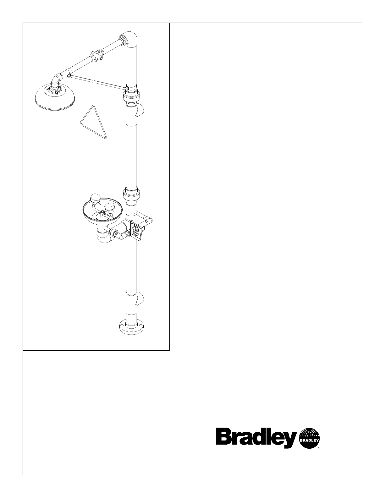
S19-310PVC
Combination Drench Shower and
Eye/Face Wash
Combiné douche oculaire/faciale
Combinación de ducha de
aspersión/lavador de ojos/rostro
Table of Contents
Pre-Installation Information . . . . . . . . . . . . . . . .2–3
Installation Instructions . . . . . . . . . . . . . . . . . . . . . .4
Assembly of Components . . . . . . . . . . . . . . . . . . . .5
Parts List . . . . . . . . . . . . . . . . . . . . . . . . . . . . . . . . .6
Table des matières
Avant l’installation . . . . . . . . . . . . . . . . . . . . . . .7–8
Instructions d’installation . . . . . . . . . . . . . . . . . . . .9
Montage . . . . . . . . . . . . . . . . . . . . . . . . . . . . . . . . .10
Liste des pièces . . . . . . . . . . . . . . . . . . . . . . . . . . .11
Contenido
Información previa a la instalación . . . . . . . . .12–13
Instrucciones de instalación . . . . . . . . . . . . . . . . . .14
Montaje de los componentes . . . . . . . . . . . . . . . . .15
Lista de piezas . . . . . . . . . . . . . . . . . . . . . . . . . . . .16
Page 2
2
S19-310PVC Installation
4/27/07 Bradley Corporation • 215-1134 Rev. R; EN 06-532G
WARNING
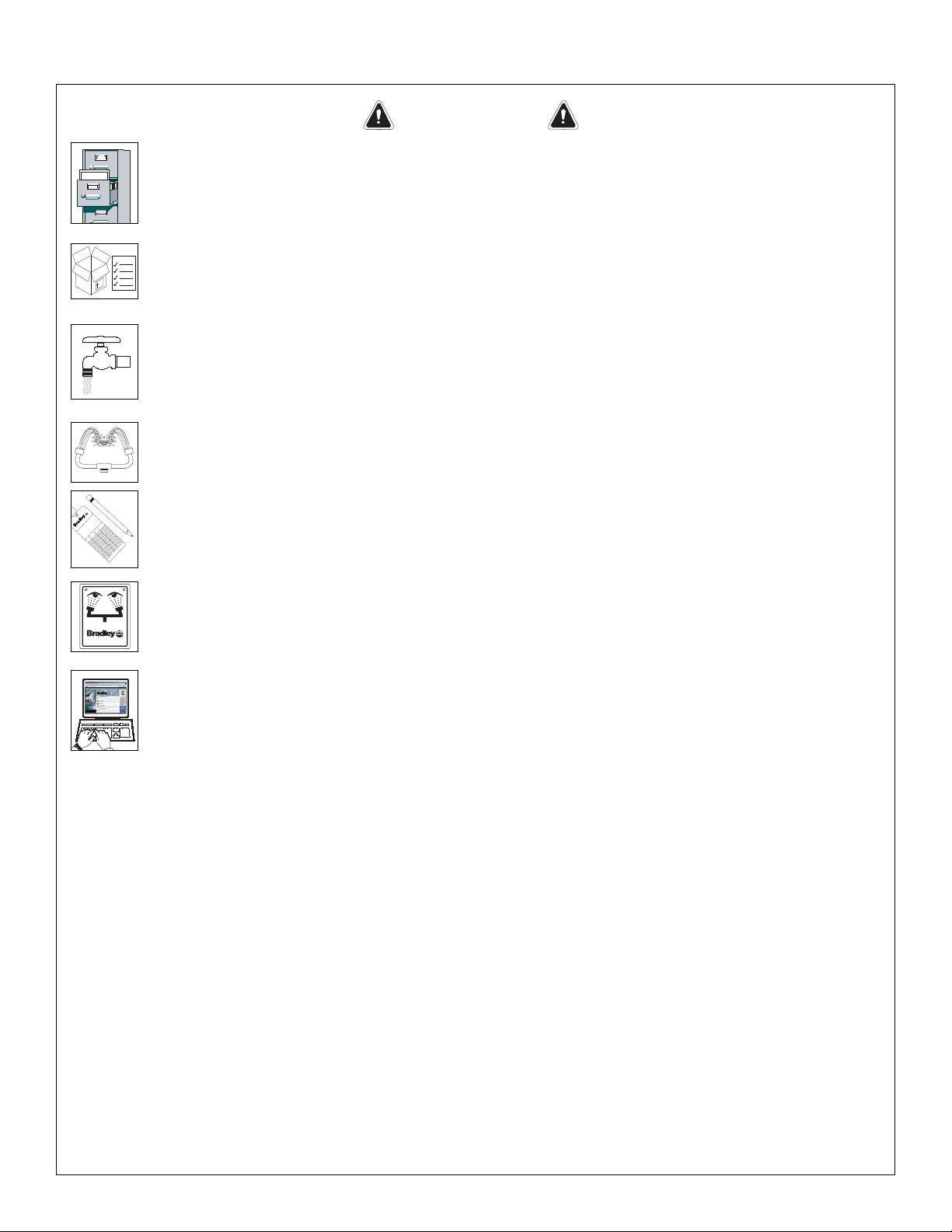
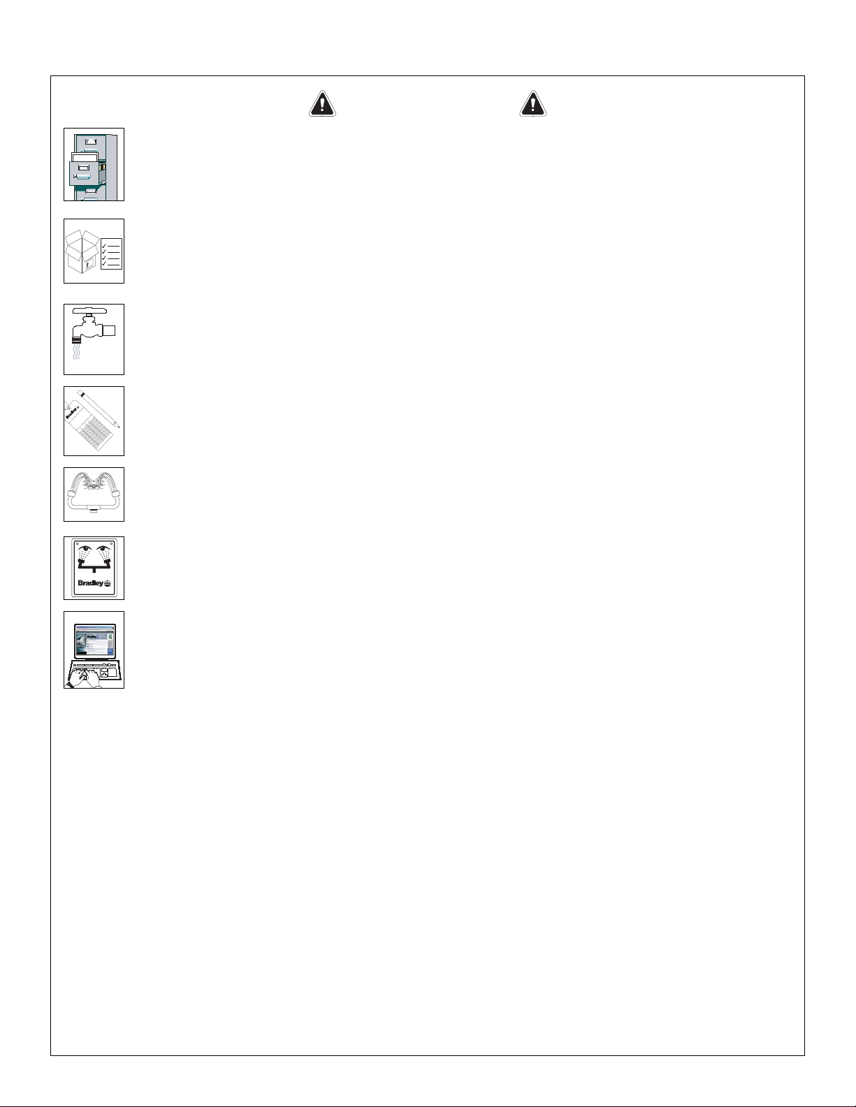
Read this installation manual completely to ensure proper installation, then file it
with the owner or maintenance department. Compliance and conformity to drain
requirements and other local codes and ordinances is the responsibility of the
installer.
Separate parts from packaging and make sure all parts are accounted for before
discarding any packaging material. If any parts are missing, do not begin
installation until you obtain the missing parts.
Flush the water supply lines before beginning installation and after installation is
complete. Test the unit for leaks and adequate water flow. Main water supply to
the eyewash should be “ON” at all times. Provisions shall be made to prevent
unauthorized shutoff.
The ANSI Z358.1 standard requires an uninterruptible supply of flushing fluid at a
minimum 30 PSI (0.21 MPa) flowing pressure. Flushing fluid should be tepid per
ANSI Z358.1.
The inspection and testing results of this equipment should be recorded weekly
to verify proper operation. This equipment should be inspected annually to
ensure compliance with ANSI Z358.1.
Workers who may come in contact with potentially hazardous materials should be
trained regarding the placement and proper operation of emergency equipment
per ANSI Z358.1.
For questions regarding the operation or installation of this product, visit
www.bradleycorp.com or call 1-800-BRADLEY.
Product warranties may also be found under ”Product Information” on our web
site at www.bradleycorp.com.
Installation
T
H
IS
S
ID
E
U
P
Packing List
!
!
!
!
P
.O
. B
o
x
3
0
9
, M
e
n
o
m
o
n
e
e
F
a
lls
, W
I 5
3
0
5
1
R
T
E
S
T
T
H
I
S
U
N
I
T
E
A
C
H
W
E
E
K
Test-operate valve(s) each week and sign below
.
R
eport any m
alfunctions imm
ediately.
Ven
til(e) w
öche
ntlich im
Testbe
trieb prüfen
, bestätig
t
durch U
ntersch
rift. Jeg
liche Störung sofort m
eld
en.
Date
Datum
Date
Signed
Unterschrift
Signe
Date
Date
Date Signed
Signed
Signed
D
I
E
S
E
S
G
E
R
Ä
T
1
S
T
W
Ö
C
H
E
N
T
L
I
C
H
Z
U
P
R
Ü
F
E
N
.
E
S
S
A
I
H
E
B
D
O
M
A
D
A
I
R
E
Test le fonctionnem
ent des va
lves chaque se
m
ain
e et
signe en bas. S
'il y à quelque chose q
u
i ne va pas fait
un rapport im
médiatem
ent.
P.O. BOX 309, MENOMONEE FALLS, WI 53052-0309 USA
TEL: 1-800-BRADLEY FAX: (262-251-5817)
http://www.bradleycorp.com
114-051
Page 3
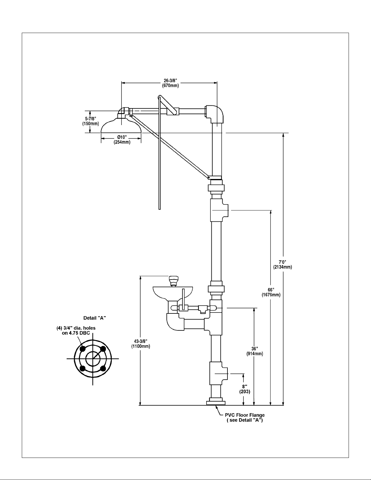
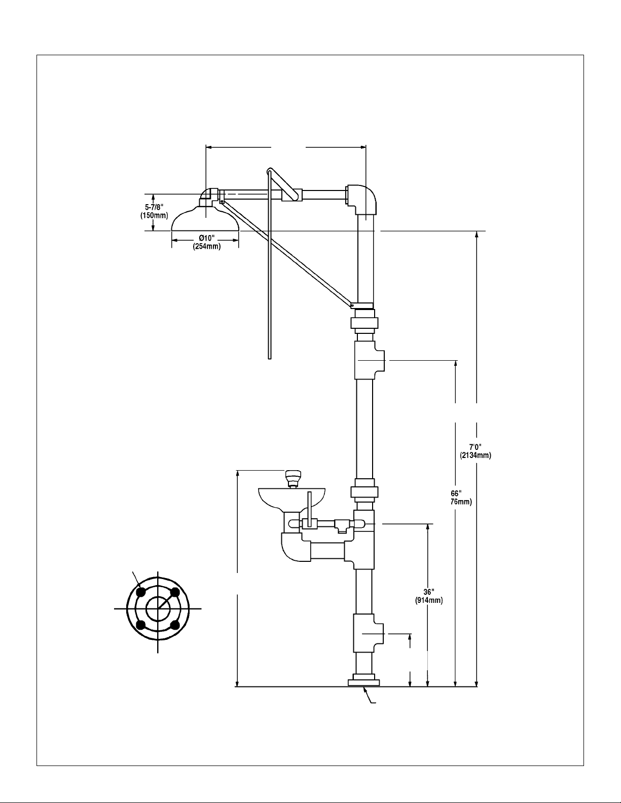
Drench Shower Unit Assembly Dimensions
3
Installation S19-310PVC
Bradley Corporation • 215-1134 Rev. R; EN 06-532G 4/27/07
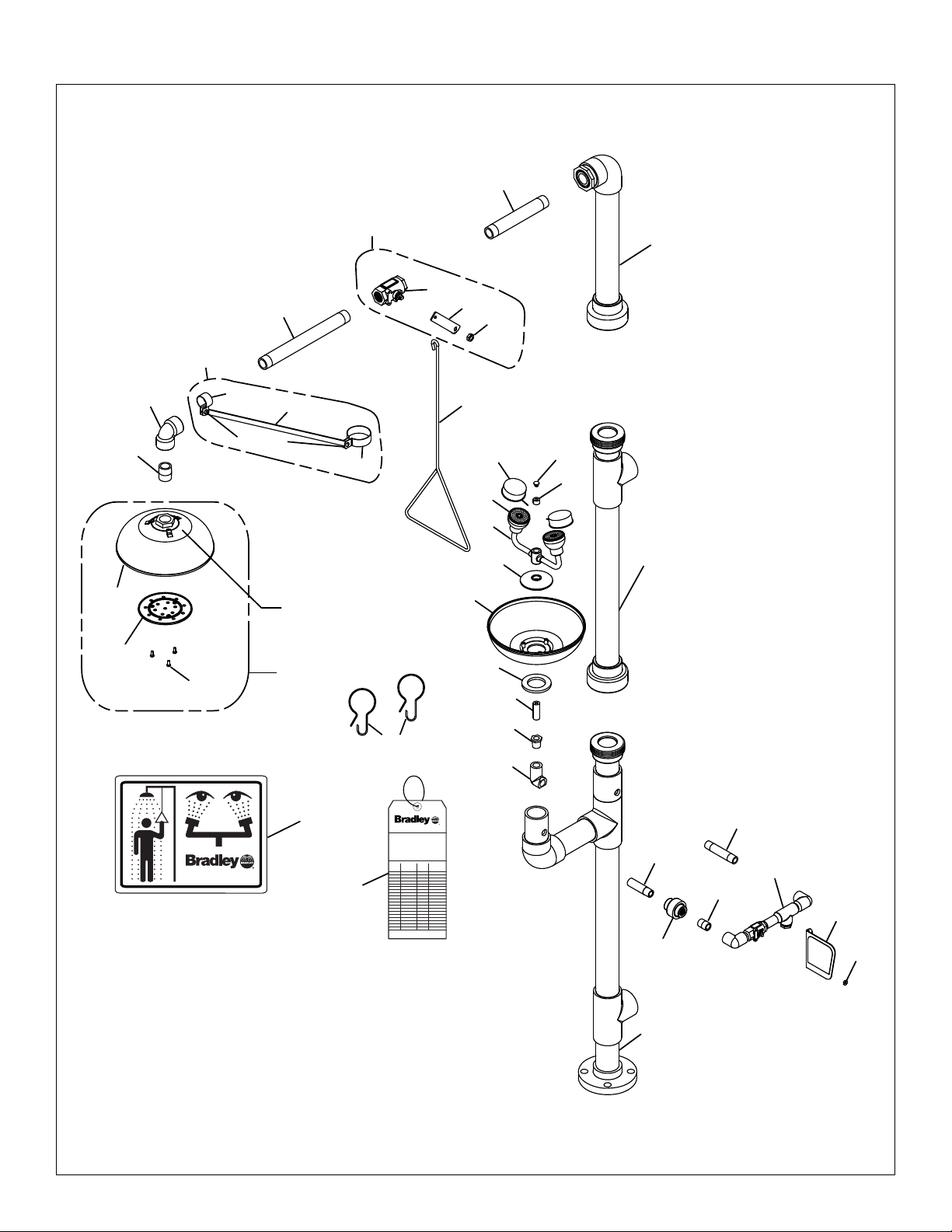
Figure 1
Page 4

4
S19-310PVC Installation
4/27/07 Bradley Corporation • 215-1134 Rev. R; EN 06-532G
Installation InstructionsInstallation Instructions
Supplies Required:
• (4) 5/8" floor anchors and bolts
• Pipe sealant and teflon tape
• Piping to 2" IPS PVC water supply inlet on unit
• Piping to 2" IPS PVC drain outlet for eye wash on unit
• Adequate supply pipe supports
• Minimum 4" (102mm) drain to accommodate 30 gallons per minute discharge for
drench shower waste
Step 1: Assemble and Install Drench Shower
1. To secure base to floor, install four suitable anchors (supplied by installer) for 5/8" bolts in the
floor (see Figure 1 on page 3).
2. Bolt the base to the floor anchors using 5/8" bolts (supplied by installer).
3. After the base is secured, assemble the remaining drench shower components as shown in Figure
1. Apply pipe sealant or tape (supplied by installer) to all male threaded pipe joints.
IMPORTANT: Some teflon sealants may cause stress cracks in the plastic
showerhead leading to failure. Use teflon tape when assembling
the showerhead.
4. The plastic showerhead should be assembled to the close nipple with teflon tape. The bottom
edge of the showerhead should be 7' (2134 mm) from the floor.
IMPORTANT: Provide adequate supports (supplied by installer) for supply pipe
using pipe hangers or other means. Do not rely on drench
shower unit to support supply piping.
5. Connect the water supply piping to the 2" PVC IPS inlet on the unit (piping supplied by
installer). Provide adequate supports (supplied by installer) for supply pipe using pipe hangers or
other means.
6. Connect the drain piping to the 2" PVC IPS drain outlet on the unit (piping supplied by
installer).
Step 2: Assemble and Install Eye/Face Wash
NOTE: See Figure 2 on page 5 for part identification.
1. While holding the elbow in the lower assembly piping, thread pipe #113-946 (Item #21) through
the hole in the lower assembly piping, and connect to elbow.
2. Install the reducer on top of the elbow.
3. Center the elbow, then tighten the pipe #113-946 (Item #21) in place.
4. Install the union and pipe nipple on pipe #113-946 (Item #21).
5. Place the gasket, then the strainer, on top of the lower assembly piping.
6. Place the eyewash bowl on top of the strainer.
7. Install the yoke assembly by connecting the stainless steel pipe, at the base of the yoke assembly,
to the reducer on the elbow.
8. Connect the pipe nipple to the valve piping assembly.
9. Open the water supply lines. Test for leaks and adequate water flow on the entire drench
shower/eye wash unit.
Page 5
Assembly of Components
1
2
3
4
5
NOTE: Use
teflon tape
only.
5.2
5.3
5.1
7
7.11
7.2
7.1
8
9
11
10
28
21
20
19
15
14.1
14
22
23
26
24
16
25
17
29
27
13
12
6
6.1
6.2
6.3
6.4, 6.5
18
P.O. BOX 309, MENOMONEE FALLS, WI 53052-0309 USA
TEL: 1-800-BRADLEY FAX: (262-251-5817)
http://www.bradleycorp.com
114-052
P.O. Box 309, Menomonee Falls, WI 53051
R
TEST THIS UNIT EACH WEEK
Test-operate valve(s) each week and sign below.
Report any malfunctions immediately.
Ventil(e) wöchentlich im Testbetrieb prüfen, bestätigt
durch Unterschrift. Jegliche Störung sofort melden.
Date
Datum
Date
Signed
Unterschrift
Signe
Date
Date
Date Signed
Signed
Signed
DIESES GERÄT 1ST WÖCHENTLICH ZU PRÜFEN.
ESSAI HEBDOMADAIRE
Test le fonctionnement des valves chaque semaine et
signe en bas. S'il y à quelque chose qui ne va pas fait
un rapport immédiatement.
30
31
5
Installation S19-310PVC
Bradley Corporation • 215-1134 Rev. R; EN 06-532G 4/27/07
Figure 2
NOTE: Seal all male threads with plastic
pipe sealant. Assemble couplings hand-tight;
then tighten one full turn with a wrench.
Page 6

6
S19-310PVC Installation
4/27/07 Bradley Corporation • 215-1134 Rev. R; EN 06-532G
Parts List
1 S90-337 1 PVC Lower Assembly
2 S90-338 1 PVC Middle Assembly
3 S90-339 1 PVC Upper Assembly
4 128-156A 1 Pull Rod - 24" Long
5 S24-070 1 Plastic Showerhead Assy.
5.1 154-057 1 Showerhead Shell
5.2 155-005 1 Diffuser
5.3 160-245 3 Screw
6 S90-341 1 2” x 1” Pipe Hanger Assembly
6.1 269-1121 1 1/2” Support Rod
6.2 269-1123 1 1” Pipe Hanger
6.3 269-1124 1 2” Pipe Hanger
6.4 160-069 2 Screw
6.5 161-047 2 Hex Nut
7 S30-061 1 1” Ball Valve Assembly
7.1 S27-276 1 1" Ball Valve with Nut
7.11 161-079 1 Jam Nut only
7.2 128-142 1 Handle
8 269-1109 1 1" PVC 90° Elbow
9 113-942 1 1” PVC Pipe x Closed Nipple
10 113-944 1 1” PVC Pipe x 8” Long
11 113-945 1 1” PVC Pipe x 12” Long
12 153-333 1 Pipe Plug
13 269-874 1 Cap Plug - Eye/Face Wash
14 S90-008 1 Valve Piping Assembly with Nut
14.1 110-215 1 Jam Nut only
15 S08-338 1 Handle
16 154-058 1 Plastic Eyewash Receptor
17 S05-131 1 Eye Wash Yoke Sub-Assembly
18 151-001 2 Curtain Hook
19 113-936 1 PVC Pipe Nipple
20 269-1114 1 PVC Union
21 113-946 1 PVC Pipe Nipple Modified
22 269-1120 1 PVC 90° Elbow
23 269-1119 1 PVC Reducer
24 124-028 1 Gasket
25 173-025 1 Cup Strainer
26 113-1151 1 Supply Pipe
27 S53-063 2 Tethered Dust Cover
28 113-940 1 1/2” Pipe Nipple
29 S05-135 2 EFW Assembly
30 114-052 1 Safety Sign
31 204-421 1 Emergency Tag
Item Part No. Qty Description
Item Part No. Qty Description
Item 6.2 includes items 6.4, 6.5
Item 6.3 includes items 6.4, 6.5
Page 7

7
Installation S19-310PVC
Bradley Corporation • 215-1134 Rev. R; EN 06-532G 4/27/07
AVERTISSEMENT
Lire ce manuel d'installation dans son intégralité pour garantir une installation
appropriée. Une fois celle-ci terminée, classer ce manuel auprès du service à la
clientèle ou d'entretien. L'installateur est responsable de la conformité de
l'installation aux codes pour des drain et codes et règlements en vigueur.
Assurez-vous que toutes les pièces sont incluses dans l’emballage et qu’il n’en
manque aucune avant de jeter l’emballage. Ne commencez pas l’assemblage
avant de recevoir les pièces manquantes.
Rincez la conduite d’alimentation avant et apres l’installation. Assurez-vous que
le débit d’eau est adéquat et qu’il n’y a pas de fuites. L’alimentation principale en
eau doit être toujours OUVERTE. On devra prévoir des dispositions pour
empêcher tout arrêt non autorisé.
La norme ANSI Z358.1 requiert une alimentation sans coupure du liquide de
rinçage à une pression minimum de 30 psi (0.21 MPa). Le liquide de rinçage doit
être tiède conformément à la norme ANSI Z358.1.
Inspectez et testez cet équipement une fois par semaine pour en assurer le bon
fonctionement. Notez les dates d’inspection. Ce matériel doit être inspecté une
fois par an pour assurer sa conformité à la norme ANSI Z358.1.
Les ouvriers susceptibles d'entrer en contact avec des matières potentiellement
dangereuses doivent recevoir une formation sur la mise en place et le bon
fonctionnement du matériel d'urgence conformément à la norme ANSI Z358.1.
Pour toute question concernant le fonctionnement ou l'installation de ce produit,
consulter le site www.bradleycorp.com ou appeler le 1-800-BRADLEY.
Les garanties de produits figurent sous la rubrique « Informations techniques »
sur notre site Internet à www.bradleycorp.com.
Installation
T
H
IS
S
I
D
E
U
P
Packing List
!
!
!
!
P
.O
. B
o
x
3
0
9
, M
e
n
o
m
o
n
e
e
F
a
lls
, W
I 5
3
0
5
1
R
T
E
S
T
T
H
I
S
U
N
I
T
E
A
C
H
W
E
E
K
Test-operate valve(s) each week and sign below
.
R
eport an
y m
alfunctions imm
ediately.
V
entil(e) w
öchentlich im T
estbetrieb prüfen, bestätigt
durc
h U
nterschrift. Jegliche Störung so
fort m
eld
en.
Date
Datum
Date
Signed
Unterschrift
Signe
Date
Date
Date Signed
Signed
Signed
D
I
E
S
E
S
G
E
R
Ä
T
1
S
T
W
Ö
C
H
E
N
T
L
I
C
H
Z
U
P
R
Ü
F
E
N
.
E
S
S
A
I
H
E
B
D
O
M
A
D
A
I
R
E
Test le fonctionnem
ent des valves ch
aque sem
aine et
signe en bas. S'il y à quelque chose q
ui n
e va pas fait
un rapport im
médiatement.
P.O. BOX 309, MENOMONEE FALLS, WI 53052-0309 USA
TEL: 1-800-BRADLEY FAX: (262-251-5817)
http://www.bradleycorp.com
114-051
Page 8

8
S19-310PVC Installation
4/27/07 Bradley Corporation • 215-1134 Rev. R; EN 06-532G
Cotes de montage du combiné douche/lave-yeux
Figure 1
Bride PVC
(voir Détail « A »)
24 in.
(610)
84 in.
(2134)
90 in.
(2286)
66 in.
(1676)
42 in.
(1007)
8 in.
(203)
Detail « A »
Trous de 3/4 in. sur
un cercle de Ø 120
mm (4.75 in.).
Page 9

9
Installation S19-310PVC
Bradley Corporation • 215-1134 Rev. R; EN 06-532G 4/27/07
Instructions d’installation
Fournitures:
• (4) Chevilles d’ancrage au sol de 5/8 in. et vis
• Produit d’étanchéité pour tuyauterie, ruban au téflon
• Tuyau d’alimentation PVC de 2 in. IPS PVC pour l’alimentation en eau à raccorder sur l’orifice
d’admission
• Tuyau PCV de 2 in. IPS pour l’évacuation (douche oculaire/faciale)
• Un nombre suffisant de supports de tuyau
• Tuyau d’évacuation d’au moins 100 mm (4 in.) pour évacuer les 30 GPM d’eau de la douche
Étape 1: Montage et installation de la douche
1. Pour fixer la base au sol, poser les trois chevilles (à fournir) pour les trois vis de 5/8 in. dans le
sol (Figure 1, p. 8).
2. Visser la base dans les chevilles avec trois vis de 5/8 in. (à fournir).
3. Une fois la base fixée monter le reste des éléments de la douche comme sur la Figure 1, page 10.
Mettre du ruban de téflon ou un produit d’étanchéité (à fournir) sur tous les filetages mâles des
raccords.
IMPORTANT: Certaines pâtes d’étanchéité au Téflon sont susceptibles de
provoquer des fissures dans le pommeau de douche en plastique, en
raison de la fatigue mécanique, et d’entraîner sa rupture. Utiliser du
ruban de téflon pour la pose du pommeau de douche en plastique.
4. Poser le pommeau de douche en plastique sur son raccord avec du ruban de téflon. Le bord
inférieur du pommeau de la douche d’urgence doit se trouver à 2,10 m (7 ft.) du sol.
IMPORTANT: Prévoir des supports adéquats (à fournir) pour la tuyauterie
d’alimentation. Ne pas utiliser la douche comme support de la
tuyauterie.
5. Raccorder le tuyau d’alimentation PVC 2 in. IPS (à fournir) sur l’orifice d’alimentation de
l’appareil. Prévoir des supports adéquats (non fournis) pour la tuyauterie d’alimentation.
6. Brancher le tuyau d’évacuation PVC de 2 in. (à fournir) sur l’orifice d’évacuation de la douche
d’urgence.
Étape 2: Assemblage des composantes de la douche oculaire/faciale
REMARQUE: Voir Figure 2, p. 10 pour identifier les pièces.
1. Tout en maintenant le coude dans la section inférieure de la tuyauterie, visser le tuyau fileté réf.
113-946 (pièce 21) dans le trou de la tuyauterie inférieure et y visser le coude.
2. Visser le réducteur sur le coude.
3. Centrer le coude et serrer le tuyau réf. 113-946 (pièce 21) en place.
4. Poser le joint et le raccord sur le tuyau réf. 113-946 (pièce 21).
5. Placer le joint et la crépine au sommet de la tuyauterie inférieure.
6. Poser la vasque sur la crépine.
7. Pour poser le guidon, raccorder le tube en acier inox sur la base du guidon au réducteur posé sur
le coude.
8. Raccorder le raccord sur la vanne.
9. Ouvrir l’alimentation en eau. S’assurer que le débit d’eau est convenable et qu’il n’y a pas de
fuites.
Page 10

10
S19-310PVC Installation
4/27/07 Bradley Corporation • 215-1134 Rev. R; EN 06-532G
Assemblage des composantes
1
2
3
4
5
NOTE: Use
teflon tape
only.
5.2
5.3
5.1
7
7.11
7.2
7.1
8
9
11
10
28
21
20
19
15
14.1
14
22
23
26
24
16
25
17
29
27
13
12
6
6.1
6.2
6.3
6.4, 6.5
18
P.O. BOX 309, MENOMONEE FALLS, WI 53052-0309 USA
TEL: 1-800-BRADLEY FAX: (262-251-5817)
http://www.bradleycorp.com
114-052
P.O. Box 309, Menomonee Falls, WI 53051
R
TEST THIS UNIT EACH WEEK
Test-operate valve(s) each week and sign below.
Report any malfunctions immediately.
Ventil(e) wöchentlich im Testbetrieb prüfen, bestätigt
durch Unterschrift. Jegliche Störung sofort melden.
Date
Datum
Date
Signed
Unterschrift
Signe
Date
Date
Date Signed
Signed
Signed
DIESES GERÄT 1ST WÖCHENTLICH ZU PRÜFEN.
ESSAI HEBDOMADAIRE
Test le fonctionnement des valves chaque semaine et
signe en bas. S'il y à quelque chose qui ne va pas fait
un rapport immédiatement.
30
31
Figure 2
REMARQUE: Mettre du produit d’étanchéité
pour plastique sur les filetages mâles. Serrer
tous les raccordements à la main puis les
serrer d’un tour complet avec une clé.
NOTE: Utiliser
uniquement du
ruban de téflon
Page 11

11
Installation S19-310PVC
Bradley Corporation • 215-1134 Rev. R; EN 06-532G 4/27/07
Liste des pièces
1 S90-337 1 Base PVC
2 S90-338 1
Portion centrale PVC
3 S90-339 1
Portion supérieure PVC
4 128-156A 1
Tige de commande long. 24 in.
5 S24-070 1
Pommeau de douche plastique
5.1 154-057 1
Pommeau
5.2 155-005 1
Diffuseur plastique
5.3 160-245 3 Vis
6 S90-341 1
Support 2 x 1 in.
6.1 269-1121 1
Tige 1/2 in.
6.2 269-1123 1
Support 1 in.
6.3 269-1124 1
Support 2 in.
6.4 160-069 2 Vis
6.5 161-047 2
Écrou
7 S30-061 1
Vanne 1 in.
7.1 S27-276 1
Vanne avec écrou
7.11 161-079 1
Écrou (seulement)
7.2 128-142 1
Levier de la vanne
8 269-1109 1
Coude PVC 1 in. 90°
9 113-942 1
Tuyau PVC 1 in. raccord fermé
10 113-944 1
Tuyau PVC 1 in. long. 8
11 113-945 1
Tuyau PVC 1 in. long. 12 in.
12 153-333 1
Bouchon
13 269-874 1
Bouchons des érogateurs
14 S90-008 1
Vanne avec écrou
14.1 110-215 1
Écrou (seulement)
15 S08-338 1
Poignée
16 154-058 1
Vasque plastique
17 S05-131 1
Eléments du guidon EFW
18 151-001 2 Crochet
19 113-936 1
Raccord PVC
20 269-1114 1
Joint PVC
21 113-946 1
Raccord PVC modifié
22 269-1120 1
Coude PVC 90°
23 269-1119 1
Réducteur PVC
24 124-028 1
Joint
25 173-025 1
Crépine
26 113-1151 1
Tuyau d’ alimentation
27 S53-063 2
Cache-poussière attaché
28 113-940 1
Raccord 1/2 in.
29 S05-135 2
Gliceur “EFW”
30 114-052 1
Panneau de sécurité
31 204-421 1
Etiquette d’urgence
Pièce Réf. Qté
Description
Pièce Réf. Qté
Description
Pièce 6.2 comprend les éléments 6.4, 6.5
Pièce 6.3 comprend les éléments 6.4, 6.5
Page 12
12
S19-310PVC Installation
4/27/07 Bradley Corporation • 215-1134 Rev. R; EN 06-532G
ADVERTENCIA
Lea en su totalidad este manual de instalación para garantizar una instalación
adecuada. Una vez que termine la instalación, entregue este manual al propietario o
al Departamento de Mantenimiento. Es responsabilidad de quien instale el equipo
cumplir con los códigos para desagüe y otra códigos y ordenanzas locales.
Separar todas las piezas del material de embalaje y asegurarse que todas las piezas
estén incluídas antes de desechar cualquier material de embalaje. Si faltase alguna
pieza, no intentar instalar la unidad combinada Bradley hasta obtener las piezas
faltantes.
Aclarar el conducto del suministro de agua antes y después de la instalación.
Verificar que no haya fugas y que el flujo de agua sea adecuado. El suministro
principal de agua a la unidad debe estar siempre en posición “ON” (abierto). Se
deben tomar medidas a fin de evitar el corte no autorizado del suministro.
La norma ANSI Z358.1 exige un suministro ininterrumpido del líquido de enjuague a
una presión mínima de 30 psi
(0.21 MPa). El líquido de limpieza debe estar tibio en
conformidad con la norma ANSI Z358.1.
Este equipo se debe inspeccionar, probar y anotar semanalmente para mantener un
funcionamiento adecuado
. Se debe revisar este equipo anualmente para asegurarse
de que cumpla con la norma ANSI Z358.1.
Los trabajadores que puedan tener contacto con materiales potencialmente
peligrosos deben recibir capacitación sobre la ubicación y operación adecuada de
los equipos de emergencia en conformidad con la norma ANSI Z358.1.
Para consultas sobre la operación o instalación de este producto, visite
www.bradleycorp.com o llame al 1-800-BRADLEY.
Las garantías del producto se pueden encontrar en "Información del producto" o en
nuestro sitio Web, www.bradleycorp.com.
Installation
T
H
IS
S
I
D
E
U
P
Packing List
!
!
!
!
P
.O
.
B
o
x
3
0
9
, M
e
n
o
m
o
n
e
e
F
a
ll
s
, W
I 5
3
0
5
1
R
T
E
S
T
T
H
I
S
U
N
I
T
E
A
C
H
W
E
E
K
Test-operate
valve(s) ea
c
h w
eek an
d sign b
elo
w.
R
epo
rt any
m
alfu
ncti
ons im
m
ediately.
V
en
til(e) wöc
hentlic
h im
T
estbetrieb
p
rü
fen, be
stätig
t
durch Un
tersc
hrift. Jegliche S
törun
g sofo
rt m
elden
.
Date
Datum
Date
Signed
Unterschrift
Signe
Date
Date
Date Signed
Signed
Signed
D
I
E
S
E
S
G
E
R
Ä
T
1
S
T
W
Ö
C
H
E
N
T
L
I
C
H
Z
U
P
R
Ü
F
E
N
.
E
S
S
A
I
H
E
B
D
O
M
A
D
A
I
R
E
Test le fonc
tio
nnem
ent des valve
s ch
aqu
e sem
aine
et
s
ig
ne en b
as. S
'il y
à quelque cho
se qu
i n
e va pas fait
un rap
port im
mé
diatem
en
t.
P.O. BOX 309, MENOMONEE FALLS, WI 53052-0309 USA
TEL: 1-800-BRADLEY FAX: (262-251-5817)
http://www.bradleycorp.com
114-051
Page 13
13
Installation S19-310PVC
Bradley Corporation • 215-1134 Rev. R; EN 06-532G 4/27/07
Dimensiones del conjunto de la unidad de ducha de aspersión
Figura 1
Agujeros de 3/4" de
diámetro en DBC de 4,75
Brida de suelo de cloruro de
polivinilo (PVC) (ver detalle “A”)
Detalle “A”
24"
(610)
84"
(2134)
90"
(2286)
66"
(1676)
8"
(203)
42"
(1007)
Page 14

14
S19-310PVC Installation
4/27/07 Bradley Corporation • 215-1134 Rev. R; EN 06-532G
Instrucciones de instalación
Materiales que se requieren:
• (4) Pernos y anclajes de suelo de 5/8"
• Obturador de tubo y cinta de teflón
• Tubo a tubo de entrada de cloruro de polivinilo (PVC) IPS de 2" de abastecimiento de agua
• Tubo a salida de drenaje de cloruro de polivinilo (PVC) IPS de 2" para el lavador de ojos/rostro
• Soportes adecuados para los tubos de abastecimiento
• Un drenaje de 102 mm (4 in.) mínimo para acomodar una descarga de 30 galones por minuto para
el consumo de la ducha de aspersión
Paso 1: Montar e instalar la ducha de aspersión
1. Para afianzar la base al suelo, instalar los cuatro anclajes apropiados (suministrados por el
instalador) para los pernos de 5/8" en el suelo (ver la figura 1 en la página 16).
2. Empernar la base a los anclajes de suelo utilizando pernos de 5/8" (suministrados por el
instalador).
3. Una vez que la base está afianzada, montar los componentes restantes de la ducha de aspersión
como se muestra en la figura 1 de la página 13. Aplicar obturador para tubos o cinta
(suministrado por el instalador) a todas las conexiones de tubo con rosca macho.
IMPORTANTE: Algunos obturadores de teflón pueden ocasionar grietas de tensión en el
cabezal de ducha de plástico, lo que a su vez puede ocasio-nar fallos.
Utilizar cinta de teflón al montar el cabezal de la ducha.
4. El cabezal de ducha de plástico debe montarse al tubo de empalme cerrado con cinta de teflón.
El borde inferior del cabezal de ducha debe estar a 2.134 mm (7 ft.) del suelo.
IMPORTANTE: Proveer soportes adecuados (suministrados por el instalador) para los
tubos de abastecimiento utilizando cuelgatubos u otros medios. No
depender de la unidad para soportar el tubo de abastecimiento.
5. Conectar el tubo de abastecimiento de agua al tubo de entrada de cloruro de polivinilo (PVC)
IPS de 2" en la unidad (tubo suministrado por el instalador). Proveer soportes adecuados
(suministrados por el instalador) para los tubos de abastecimiento
utilizando cuelgatubos u otros medios.
6. Conectar el tubo de drenaje a la salida de drenaje de cloruro de polivinilo (PVC) IPS de
2" en la unidad (tubo suministrado por el instalador).
Paso 2: Montar e instalar el lavador de ojos/rostro
NOTA: Ver la figura 2 de la página 15 para obtener información sobre la identificación de las piezas
1. Mientras se sujeta el codo en el tubo del conjunto inferior, enroscar el tubo nº 113-946 (artículo
nº 21) a través del agujero en el tubo del conjunto inferior, y conectar al codo
2. Instalar el reductor sobre el codo.
3. Centrar el codo, luego apretar el tubo nº 113-946 (artículo nº 21) en su lugar
4. Instalar la unión y el empalme de tubo en el tubo nº 113-946 (artículo nº 21).
5. Colocar la junta y luego el depurador sobre los tubos del conjunto inferior.
6. Colocar la pila del lavador de ojos/rostro sobre el depurador.
7. Instalar el conjunto de horquilla conectando la tubería de acero inoxidable en la base del
conjunto de horquilla al reductor en el codo.
8. Conectar el empalme del tubo al conjunto de tubos de la válvula.
9. Abrir los tubos de abastecimiento de agua. Comprobar que no haya fugas y que el caudal de
agua sea adecuado en toda la unidad de ducha de aspersión/lavador de ojos/rostro.
Page 15

Armado de los componentes
1
2
3
4
5
NOTE: Use
teflon tape
only.
5.2
5.3
5.1
7
7.11
7.2
7.1
8
9
11
10
28
21
20
19
15
14.1
14
22
23
26
24
16
25
17
29
27
13
12
6
6.1
6.2
6.3
6.4, 6.5
18
P.O. BOX 309, MENOMONEE FALLS, WI 53052-0309 USA
TEL: 1-800-BRADLEY FAX: (262-251-5817)
http://www.bradleycorp.com
114-052
P.O. Box 309, Menomonee Falls, WI 53051
R
TEST THIS UNIT EACH WEEK
Test-operate valve(s) each week and sign below.
Report any malfunctions immediately.
Ventil(e) wöchentlich im Testbetrieb prüfen, bestätigt
durch Unterschrift. Jegliche Störung sofort melden.
Date
Datum
Date
Signed
Unterschrift
Signe
Date
Date
Date Signed
Signed
Signed
DIESES GERÄT 1ST WÖCHENTLICH ZU PRÜFEN.
ESSAI HEBDOMADAIRE
Test le fonctionnement des valves chaque semaine et
signe en bas. S'il y à quelque chose qui ne va pas fait
un rapport immédiatement.
30
31
15
Installation S19-310PVC
Bradley Corporation • 215-1134 Rev. R; EN 06-532G 4/27/07
Figura 2
NOTA: Sellar todas las roscas macho con
obturador de tubo de plástico. Montar los
acoplamientos apretándolos a mano; luego,
apretar una vuelta completa más con una
llave para tuercas.
NOTA: Usar
cinta de
teflon
solamente
Page 16

16
S19-310PVC Installation
4/27/07 Bradley Corporation • 215-1134 Rev. R; EN 06-532G
Lista de piezas
1 S90-337 1
Conjunto de cloruro de
polivinilo (PVC) inferior
2 S90-338 1
Conjunto de cloruro de
polivinilo (PVC) intermedio
3 S90-339 1
Conjunto de cloruro de
polivinilo (PVC) superior
4 128-156A 1
Barra de tiro de 24"
5 S24-070 1
Conjunto de cabezal de ducha
5.1 154-057 1
Cabezal de ducha de plástico
5.2 155-005 1
Difusor de plástico
5.3 160-245 3
Tornillo
6 S90-341 1
Conjunto de cuelgatubos de 2" x 1"
6.1 269-1121 1
Barra de soporte de 1/2"
6.2 269-1123 1
Cuelgatubos de 1"
6.3 269-1124 1
Cuelgatubos de 2"
6.4 160-069 2
Tornillo
6.5 161-047 2
Tuerca hexagonal
7 S30-061 1
Conjunto de válvula esférica de 1"
7.1 S27-276 1
Válvula esférica 1" con tuerca
7.11 161-079 1 T
uerca (solamente)
7.2 128-142 1
Manilla
8 269-1109 1
Codo de 90° de cloruro de
polivinilo (PVC) de 1"
9 113-942 1
Tubo de cloruro de polivinilo (PVC)
de 1" x empalme cerrado
10 113-944 1
Tubo de cloruro de polivinilo (PVC)
de 1" x 8"
11 113-945 1
Tubo de cloruro de polivinilo (PVC)
de 1" x 12"
12 153-333 1
Tapón de tubería
13 269-874 1
Tapón - Lavaojos
14 S90-008 1
Conjunto de tubos de la válvula
14.1 110-215 1
Contratuerca (servicio)
15 S08-338 1
Manilla
16 154-058 1
Receptor de plástico EFW
17 S05-131 1
Conjunto de horquilla EFW
18 151-001 2
Gancho
19 113-936 1
Empalme para tubo de cloruro
de polivinilo (PVC)
20 269-1114 1
Unión de cloruro de polivinilo (PVC)
21 113-946 1
Empalme para tubo de cloruro de
polivinilo (PVC) modificado
22 269-1120 1
Codo de 90° de cloruro de
polivinilo (PVC)
23 269-1119 1
Reductor de cloruro de polivinilo
(PVC)
24 124-028 1
Junta
25 173-025 1
Depurador
26 113-1151 1
Tubería de suministro
27 S53-063 2
Cubierta para polvo
28 113-940 1
Empalme para tubo de 1/2 pulg.
29 S05-135 2
Conjunto EFW
30 114-052 1
Señal de seguridad
31 204-421 1
Etiqueta de emergencia
Art. Nº de Pieza Cant.
Descripción
Art. Nº de Pieza Cant.
Descripción
Art. 6.2 incluye art. 6.4, 6.5
Art. 6.3 incluye art. 6.4, 6.5
 Loading...