

Page 1
P.O. Box 309, Menomonee Falls, WI USA 53052-0309
PHONE 1-800-BRADLEY FAX (262) 251-5817
http://www.bradleycorp.com
215-158HFP Rev. J; EN 07-519
© 2007 Bradley Corporation
Page 1 of 6 8/9/07
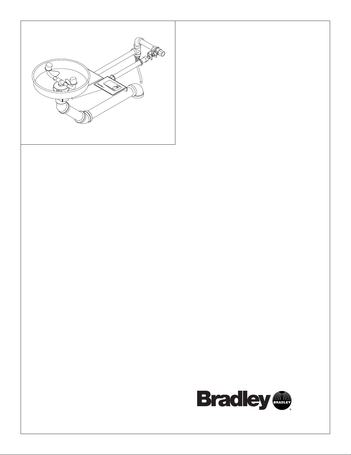
S19-220HFP
Stainless Steel Wall-Mounted
Eyewash
Table of Contents
Pre-Installation Information . . . . . . . . . . . . . . 2
Dimensions . . . . . . . . . . . . . . . . . . . . . . . . . . . .3
Installation Instructions . . . . . . . . . . . . . . . . . . 4
Assembly of Components . . . . . . . . . . . . . . . . 5
Parts List . . . . . . . . . . . . . . . . . . . . . . . . . . . . . 6
Installation
14-063
1
P
.
O
T
E
.
w
B
L
w
O
:
1
w
X
-
.
8
b
3
0
0
r
0
a
9
-
d
,
B
l
M
e
R
y
E
A
c
N
D
o
O
r
L
p
M
E
.
c
Y
O
o
N
m
E
F
E
A
X
F
A
:
(
L
2
L
6
S
2
,
2
W
5
I
1
5
5
3
8
0
1
5
7
2
)
0
3
0
9
U
S
A
Page 2
2
S19-220HFP Installation
8/9/07 Bradley Corporation • 215-158HFP Rev. J; EN 07-519
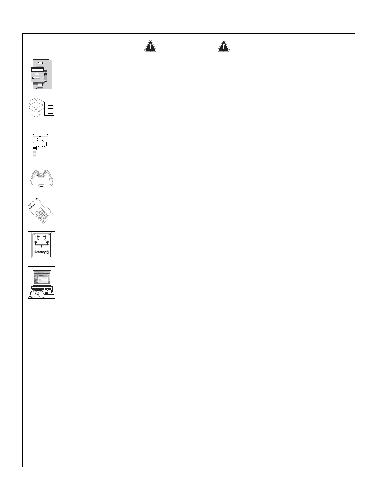
WARNING
Read this installation manual completely to ensure proper installation, then file it
with the owner or maintenance department. Compliance and conformity to drain
requirements and other local codes and ordinances is the responsibility of the
installer.
Separate parts from packaging and make sure all parts are accounted for before
discarding any packaging material. If any parts are missing, do not begin
installation until you obtain the missing parts.
Flush the water supply lines before beginning installation and after installation is
complete. Test the unit for leaks and adequate water flow. Main water supply to
the eyewash should be “ON” at all times. Provisions shall be made to prevent
unauthorized shutoff.
The ANSI Z358.1 standard requires an uninterruptable supply of flushing fluid at
a minimum 30 PSI (0.21 MPa) flowing pressure. Flushing fluid should be tepid per
ANSI Z358.1.
The inspection and testing results of this equipment should be recorded weekly
to verify proper operation. This equipment should be inspected annually to
ensure compliance with ANSI Z358.1.
Workers who may come in contact with potentially hazardous materials should be
trained regarding the placement and proper operation of emergency equipment
per ANSI Z358.1.
For questions regarding the operation or installation of this product, visit
www.bradleycorp.com or call 1-800-BRADLEY.
Product warranties may also be found under ”Product Information” on our web
site at www.bradleycorp.com.
Installation
P
.O
. Bo
x
3
0
9
,
M
e
n
o
m
o
n
e
e
F
a
lls
,
W
I 5
3
0
5
1
R
T
E
S
T
T
H
I
S
U
N
I
T
E
A
C
H
W
E
E
K
Te
s
t-o
perate v
alv
e(s) each w
eek and
sign
belo
w
.
R
eport an
y m
alfunction
s
im
m
ed
iat
el
y.
Ventil(e) w
ö
c
he
ntlic
h im
Te
s
tbetrie
b prüf
en,
be
stäti
gt
du
rc
h U
nter
sc
hrift. Je
glic
he S
törun
g sofo
r
t melden
.
Date
Datum
Date
Signed
Unter
sc
hrift
Signe
Date
Date
Date
Signed
Signed
Signed
D
I
E
S
E
S
G
E
R
Ä
T
1
S
T
W
Ö
C
H
E
N
T
L
I
C
H
Z
U
P
R
Ü
F
E
N
.
E
S
S
A
I
H
E
B
D
O
M
A
D
A
I
R
E
Te
s
t le fo
nction
nem
e
nt de
s v
alve
s
c
haque
sem
aine et
signe e
n ba
s.
S'il y
à qu
elqu
e c
ho
se qui ne v
a pa
s fait
un rap
por
t im
m
édia
temen
t.
Packing List
•
•
•
IS
H
T
E
ID
S
P
•
U
P.O. BOX 309, MENOMONEE FALLS, WI 53052-0309 USA
TEL: 1-800-BRADLEY FAX: (262-251-5817)
http://www.bradleycorp.com
114-051
Page 3

3
Installation S19-220HFP
Bradley Corporation • 215-158HFP Rev. J; EN 07-519 8/9/07
S19-220HFP Dimensions
Figure 1
NOTE: All dimensions assume standard thread engagement. Variations in manufacturing
allow for +/- 1/8" (3mm) per threaded joint.To find the tolerance of a dimension, add
the number of thread joints in between a dimension and multiply it by 1/8" (3mm).
6-15/16"
(176mm)
1/2" IPS Supply
13-1/2"
(343mm)
P.O. BOX 309, MENOMONEE FALLS, WI 53052-0309 USA
TEL: 1-800-BRADLEY FAX: (262-251-5817)
www.bradleycorp.com
114-063
4"
(102mm)
15-3/8" (391mm)
Ø 10-3/4" (254mm)
5/16" x 1-1/4"
(8mm x 32mm)
MOUNTING
SLOTS FOR
1/4" BOLTS
7-3/8"
(187mm)
41-3/8"
(1051mm)
Suggested
Height
To Floor
1/4"
(6mm)
5-9/16"
(141mm)
Ø 1"
(25mm)
(216mm)
1-1/4" IPS Drain
2-3/8"
(60mm)
8-1/2"
Ø 2" (51mm)
Ø 1"
(25mm)
35-11/16"
(906mm)
Suggested
Height
To Floor
Page 4

4
S19-220HFP Installation
8/9/07 Bradley Corporation • 215-158HFP Rev. J; EN 07-519
Installation Instructions
Supplies Required:
• (2) 1/4" wall fasteners and bolts
• Pipe sealant
• Piping to 1/2" IPS water supply inlet and piping to 1-1/4" IPS drain outlet
• Sign-mounting hardware
Step 1: Mount eyewash and install supply piping
NOTE: The top of the eyewash heads should be 33"–45" (838mm–1143mm) from the floor. Refer to
Figure 1 on page 3 for appropriate dimensions.
1. Drill supply, drain, and operating rod holes at the dimensions shown in Figure 1.
2. Secure the eyewash receptor assembly to the wall using appropriate wall anchors and bolts (supplied
by installer).
3. Install the drain and supply piping (a
pply pipe sealant to all male-threaded pipe joints).
Step 2: Secure operating support sleeve
NOTE: This unit has been designed to accommodate varying wall thicknesses. When installing the
operating stem support sleeve (Item 19) it will be necessary to cut off one or both ends of the sleeve so
that 5/8" of threaded pipe protrudes from both sides of the wall.
1. Insert the operating support sleeve through the wall and secure in place with the nuts and washers
provided.
A slip joint has been provided for adjustment and is located directly below the automatic
weep drain fitting (Item 11).
Step 3: Assemble components
NOTE: Refer to the illustration on page 5 for component assemblies.
1. Assemble the components in the following order over the non-threaded end of the brass tube (Item 12):
connector kit (Item 13), brass friction ring (Item 15) and rubber washer (Item 14).
2. Insert the non-threaded end into the pipe (Item 8).
3. Align and screw the threaded end into the automatic weep drain. Tighten the nut (Item 13) on the pipe.
4. Insert the operating rod (Item 22) through the sleeve and attach handles (Items 23 and 24) with
the nuts and lockwashers provided.
Step 4: Connect water supply
1. Tighten all pipes and fittings maintaining proper alignment.
2. Connect the water supply piping to the 1/2" IPS inlet on the eyewash (piping supplied by
installer).
3. Connect drain piping to the 1-1/4" IPS drain outlet on the eyewash (piping supplied by installer).
4. Mount safety sign to wall using sign mounting hardware (supplied by installer).
5. Open the water supply lines. Test for leaks and adequate water flow.
Page 5

5
Installation S19-220HFP
Bradley Corporation • 215-158HFP Rev. J; EN 07-519 8/9/07
Assembly of Components
Figure 2
NOTE: Items 1.1-1.10 come preassembled as Item 1.
1.10
R
P.O. Box 309, Menomonee Falls, WI 53051
TEST THIS UNIT EACH WEEK
DIESES GERÄT 1ST WÖCHENTLICH ZU PRÜFEN.
ESSAI HEBDOMADAIRE
Test-operate valve(s) each week and sign below.
Report any malfunctions immediately.
Ventil(e) wöchentlich im Testbetrieb prüfen, bestätigt
durch Unterschrift. Jegliche Störung sofort melden.
Test le fonctionnement des valves chaque semaine et
signe en bas. S'il y à quelque chose qui ne va pas fait
un rapport immédiatement.
Date
Signed
Date Signed
Datum
Unterschrift
Date
Date
Signe
Date
Signed
Signed
1.5
1.6
1.7
1.8
1.9
Flow Control
This End
27
1
16
28
1.4
1.3
1.2
1.1
10
11
17
114-051
P.O. BOX 309, MENOMONEE FALLS, WI 53052-0309 USA
TEL: 1-800-BRADLEY FAX: (262-251-5817)
http://www.bradleycorp.com
7
8
9
25
26
18
1/2" IPS
Supply Inlet
24
22.1
6
14
26
5
1-1/4" IPS
2
3
Drain Outlet
21
20
13
12
22
18.1
19
4
-063
114
P.O
TEL: 1-80
. B
w
ww.bradle
OX
3
09, MEN
0-BRAD
ycorp.co
OMO
LEY F
NEE
m
AX
F
ALLS, WI 530
:
(262-251-5817)
52-0
13
309 U
S
A
25
15
23
21
20
Page 6

6
S19-220HFP Installation
8/9/07 Bradley Corporation • 215-158HFP Rev. J; EN 07-519
Parts List
1 S90-302 1 Stainless Steel Bowl Assembly
1.1 111-039 1 Inlet-Drain Fitting
1.2 124-028 1 Gasket
1.3 140-645 1 Wall Bracket
1.4 124-024 1 Washer
1.5 187-053 1 Stainless Steel Bowl
1.6 173-009 1 Cup Strainer
1.7 S21-071 1 Supply Pipe Assy.
1.8 113-1159 1 Spacer, Drain
1.9 S05-091 1 Eyewash Yoke
1.10 107-371 2 Dust Cover
2 169-850 1 45° Street Elbow 1-1/4" IPS
3 113-006LT 1 Pipe 1-1/4" IPS x 6-1/2" Lg.
4 169-849 1 45° Elbow 1-1/4" IPS
5 113-006NQ 1 (0-8" wall)Pipe 1-1/4" IPS x 12-1/16"
113-006NT 1 (8-12" wall)Pipe 1-1/4" IPS x 16-1/16"
113-006NW 1 (12-18" wall)Pipe 1-1/4" IPS x 22-1/16"
6 169-764 1 Elbow 1-1/4" IPS
7 269-882 1 Connector
8 R68-600015 4 ft. Tube
9 113-006NP 1 (0"-8" wall) Pipe 1/2" IPS x 18-3/8"
113-006NS 1 (8"-12" wall) Pipe 1/2" IPS x 28-3/8"
113-006NV 1 (12"-18" wall) Pipe 1/2" IPS x 28-3/8"
10 169-838 1 Pipe Tee 1/2"
11 S29-068 1 Weep Valve Assy.
12 142-002DA 1 Washer
13 110-191 2 Connector Nut
14 110-115 1 Nut
15 153-372R 1 Adapter, Ball Valve
16 169-025 1 90° Street Elbow 1/2" IPS
17 113-006MS 1 Pipe 1/2" IPS x 3-3/4" lg.
18 S27-282 1 Stay-Open Ball Valve 1/2" IPS w/Nut
18.1 110-215 1 Nut only
19 113-006NN 1 (0"-8")pipe sleeve 1/2" IPS x 9-1/4"
113-006NR 1 (8"-12")pipe sleeve 1/2" IPS x 13-1/4"
113-006NU 1 (12"-18")pipe sleeve 1/2" IPS x 19-1/4"
20 142-002F 2 Washer-Metal
21 124-001F 2 Washer-Fiber
22 S21-067 1 (0"-8") Operating Rod
S21-067A 1 (8"-12") Operating Rod
S21-067B 1 (12"-18") Operating Rod
22.1 132-042 2 Retaining Ring
23 S08-308 1 Handle Assy.
24 128-151 1 Handle
25 161-036 2 Nut-Hex 5/16-18 Stn. Stl.
26 142-002BK 2 Lockwasher
27 114-051 1 Safety Sign
28 204-421 1 Emergency Tag
Item Part No. Qty Description
Item Part No. Qty Description
Prepack S45-1782 includes Items 1.4, 1.6, 1.7, 1.8
 Loading...