

Page 1
Installation
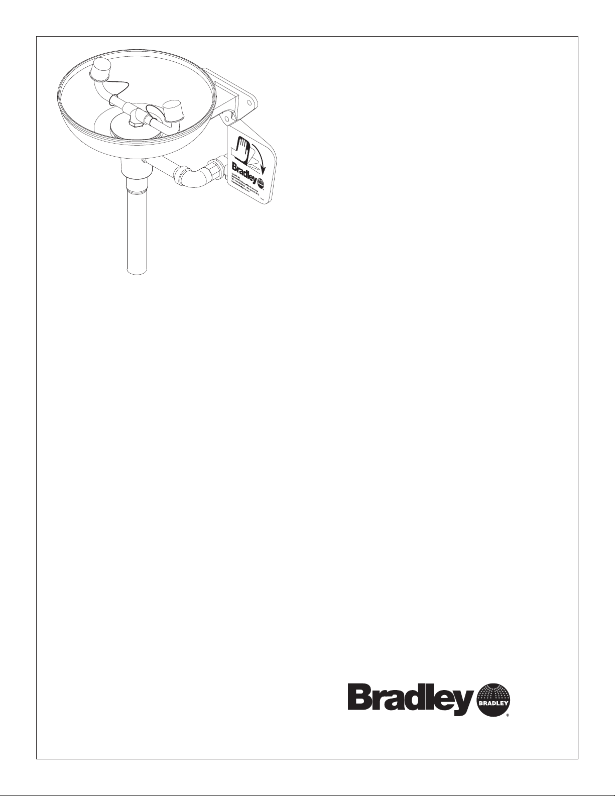
S19-220
Wall-Mounted Eyewash
Douche oculaire murale
Lavador de ojos para montaje
en pared
Table of Contents
Pre-Installation Information . . . . . . . . . . . . . . 2
Installation Instructions. . . . . . . . . . . . . . . . . . 3
Assembly of Components . . . . . . . . . . . . . . . 4
Parts List . . . . . . . . . . . . . . . . . . . . . . . . . . . . 4
Table des matières
Avant l’installation. . . . . . . . . . . . . . . . . . . . . . 5
Instructions d’installation . . . . . . . . . . . . . . . . 6
Assemblage des composantes . . . . . . . . . . . 7
Liste des pièces . . . . . . . . . . . . . . . . . . . . . . . 7
Contenido
Información previa a la instalación. . . . . . . . . 8
Instrucciones de instalación. . . . . . . . . . . . . . 9
Armado de los componentes . . . . . . . . . . . . 10
Lista de piezas . . . . . . . . . . . . . . . . . . . . . . . 10
215-158 Rev. W; ECN 08-503
© 2008 Bradley Corporation
Page 1 of 10 2/4/08
P.O. Box 309, Menomonee Falls, WI USA 53052-0309
PHONE 1-800-BRADLEY FAX (262) 251-5817
bradleycorp.com
Page 2
S19-220 Installation
IMPORTANT
Installation
R
1
5
0
3
I 5
W
,
s
ll
a
F
e
e
n
o
R
P
m
o
U
n
Z
e
H
M
,
IC
9
L
0
K
T
3
E
N
E
x
E
eek an
o
H
W
C
B
H
.
Ö
h w
C
O
c
E
.
W
A
P
R
I
T
E
s immed
S
A
T
I
D
1
Testbe
N
A
T
e(s) ea
U
Ä
M
R
S
O
I
alv
h im
E
D
H
eglic
T
B
G
alfunction
tlic
E
S
T
E
S
H
I
S
E
y m
hen
T
A
E
hrift. J
I
perate v
S
D
öc
S
E
nnem
'il y
ntersc
Test-o
eport an
m
R
as. S
fonctio
Ventil(e) w
t im
durch U
e en b
Test le
rappor
sign
un
Date
Datum
Date
114-051
.
N
E
F
Ü
belo
d sign
.
y
el
prüfen,
iat
b
g s
trie
törun
es
he S
alv
e c
es v
ent d
ent.
à quelqu
édiatem
Signed
Unterschrift
Signe
.
w
ätigt
est
elden.
b
aine et
t m
as fait
or
a p
of
e v
chaque sem
se qui n
ho
Date
Date
Date
P.O. BOX 309, MENOMONEE FALLS, WI 53052-0309 USA
TEL: 1-800-BRADLEY FAX: (262-251-5817)
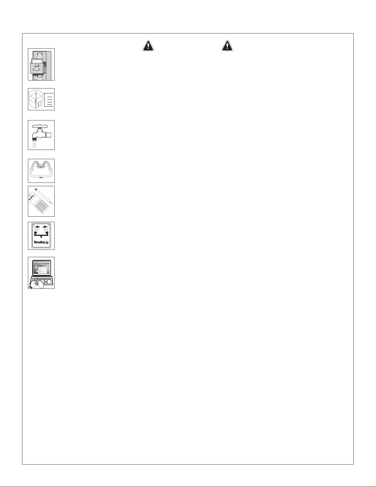
Read this installation manual completely to ensure proper installation, then file it
with the owner or maintenance department. Compliance and conformity to drain
requirements and other local codes and ordinances is the responsibility of the installer.
Separate parts from packaging and make sure all parts are accounted for before
Packing List
•
•
•
THIS
SIDE
UP
discarding any packaging material. If any parts are missing, do not begin installation
•
until you obtain the missing parts.
Flush the water supply lines before beginning installation and after installation is
complete. Test the unit for leaks and adequate water flow. Main water supply to the
eyewash should be “ON” at all times. Provisions shall be made to prevent unauthorized
shutoff.
The ANSI Z358.1 standard requires an uninterruptible supply of flushing fluid at a
minimum 30 PSI (0.21 MPa) flowing pressure. Flushing fluid should be tepid per ANSI
Z358.1.
Signed
Signed
Signed
The inspection and testing results of this equipment should be recorded weekly to verify
proper operation. This equipment should be inspected annually to ensure compliance
with ANSI Z358.1.
Workers who may come in contact with potentially hazardous materials should be
trained regarding the placement and proper operation of emergency equipment per ANSI
http://www.bradleycorp.com
Z358.1.
For questions regarding the operation or installation of this product, visit www.
bradleycorp.com or call 1-800-BRADLEY.
Product warranties may also be found under ”Product Information” on our web site at
www.bradleycorp.com.
2
2/4/08 Bradley Corporation • 215-158 Rev. W; ECN 08-503
Page 3
Installation S19-220
Installation
Supplies Required:
• (3) 3/8” wall fasteners and bolts
• Pipe sealant
• Piping to 1/2” NPT water supply inlet on unit
• Piping to 1-1/4” NPT drain outlet for eyewash
• Sign-mounting hardware
NOTE: Local codes may require the installation
of a backfl ow prevention valve to complete proper
installation. Compliance with local codes is the
responsibility of the installer. Valve must be tested
annually to verify that it is functioning properly.
Backfl ow prevention valves are not included with
the fi xture and may be supplied by the contractor
or purchased from Bradley Corporation.
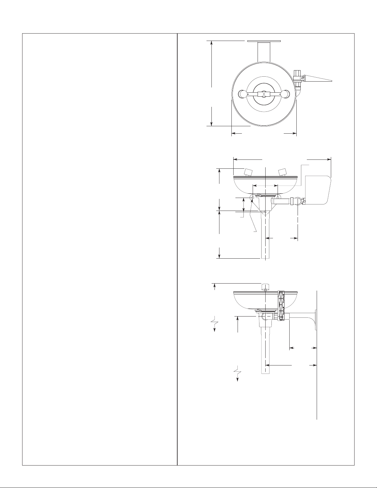
Step 1: Install inlet drain fitting
NOTE: The top of the eyewash heads should be
33”–45” (838mm–1143mm) from the floor.
1. Position the inlet drain fitting over the
1-1/4” drain outlet pipe from wall.
2. Using the inlet drain fitting as a template,
mark the bolt hole locations on wall OR
install three suitable fasteners (supplied
by installer) for 3/8” bolts in the wall at the
marked hole locations.
3. Bolt the inlet drain fitting to the wall or wall
fasteners using 3/8” bolts (supplied by
installer).
13-1/4"
(337mm)
7-3/8"
(187mm)
7-1/4"
(184mm)
2-1/4"
(57mm)
Ø 5/16"
(8mm)
Ø 10" (254mm)
15-1/2" (394mm)
4"
(102mm)
5-1/4"
(133mm)
Step 2: Assemble components
1. Assemble the remaining eyewash
components as shown on page 4.
• Apply pipe sealant (supplied by installer) to
all male-threaded pipe joints.
• Use a strap wrench around pipes when
tightening to prevent pipe marring.
Step 3: Connect water supply
1. Connect the water supply piping to the 1/2”
NPT inlet on the eyewash (piping supplied by
installer).
2. Connect the tailpiece to the 1-1/4” NPT drain
outlet on the eyewash.
3. Mount the safety sign to the wall using signmounting hardware (supplied by installer).
4. Open the water supply lines. Test for leaks
and adequate water flow.
36" (914mm)
Suggested
Height
To Floor
30-1/2"
(775mm)
Suggested
Height
To Floor
NOTE: All dimensions assume standard thread
engagement. Variations in manufacturing allow for
+/- 1/8 (3mm) per threaded joint. To fi nd the tolerance
of a dimension, add the number of thread joints in
between a dimension and multiply it by 1/8 (3mm).
4-1/2"
(114mm)
8-1/4"
(210mm)
Wall
Bradley Corporation • 215-158 Rev. W; ECN 08-503 2/4/08
3
Page 4

S19-220 Installation
Assembly of Components and Parts List
1.8
8
1.7
1.6
1.5
1.2
1.1
1-1/4" NPT
Drain Outlet
Flow Control
This End
1.4
1.3
2
7
1
114-051
P.O. BOX 309, MENOMONEE FALLS, WI 53052-0309 USA
TEL: 1-800-BRADLEY FAX: (262-251-5817)
http://www.bradleycorp.com
9
R
P.O. Box 309, Menomonee Falls, WI 53051
TEST THIS UNIT EACH WEEK
DIESES GERÄT 1ST WÖCHENTLICH ZU PRÜFEN.
ESSAI HEBDOMADAIRE
Test-operate valve(s) each week and sign below.
Report any malfunctions immediately.
Ventil(e) wöchentlich im Testbetrieb prüfen, bestätigt
durch Unterschrift. Jegliche Störung sofort melden.
Test le fonctionnement des valves chaque semaine et
signe en bas. S'il y à quelque chose qui ne va pas fait
un rapport immédiatement.
Date
Signed
Date Signed
Datum
Unterschrift
Date
Signed
Date
Signe
Date
Signed
1/2" NPT
Supply Inlet
4
6
3
5
4.1
Item Part No. Qty Description
1 S90-293 1 Plastic Bowl Assembly
1.1 111-061 1 Inlet Drain Fitting
1.2 124-028 1 Gasket
1.3 154-058 1 Plastic Receptor
1.4 173-025 1 Cup Strainer
1.5 S21-071 1 Supply Stem
1.6 113-1185 1 Spacer, Drain
1.7 S05-091 1 Eyewash Yoke Assembly
1.8 107-371 2 Dust Cover
Prepack S45-123 includes Items 4.1, 5, 6
Prepack S45-122 includes Items 4, 4.1, 5, 6
Prepack S45-1785 includes Items 1.2, 1.4, 1.5, 1.6
4
NOTE: Items 1.1-1.8 come preassembled as Item 1.
Item Part No. Qty Description
2 113-006LQ 1 1/2” NPT Pipe x 3-1/2”
3 169-025 1 Elbow
4 S27-282 1 1/2” Ball Valve with Nut
4.1 110-215 1 Nut only
5 128-135 1 Handle, Plastic
6 142-002DA 1 Washer
7 269-167 1 Tailpiece
8 114-051 1 Safety Sign
9 204-421 1 Inspection Tag
2/4/08 Bradley Corporation • 215-158 Rev. W; ECN 08-503
Page 5

Installation S19-220
IMPORTANT
Lire ce manuel d’installation dans son intégralité pour garantir une installation
Installation
THIS
SIDE
UP
appropriée. Une fois celle-ci terminée, classer ce manuel auprès du service à la clientèle
ou d’entretien. L’installateur est responsable de la conformité de l’installation aux codes
pour des drain et codes et règlements en vigueur.
Assurez-vous que toutes les pièces sont incluses dans l’emballage et qu’il n’en manque
Packing List
•
•
•
aucune avant de jeter l’emballage. Ne commencez pas l’assemblage avant de recevoir
•
les pièces manquantes.
Rincez la conduite d’alimentation avant et apres l’installation. Assurez-vous que le débit
d’eau est adéquat et qu’il n’y a pas de fuites. L’alimentation principale en eau doit être
toujours OUVERTE. On devra prévoir des dispositions pour empêcher tout arrêt non
autorisé.
La norme ANSI Z358.1 requiert une alimentation sans coupure du liquide de rinçage
à une pression minimum de 30 psi (0.21 MPa). Le liquide de rinçage doit être tiède
conformément à la norme ANSI Z358.1.
R
1
5
0
3
I 5
W
,
s
ll
a
.
.
N
F
e
E
w
e
F
n
Ü
.
elo
o
R
b
P
m
o
estätigt
U
n
b
Z
e
H
d sign
t melden
, M
IC
y.
as fait
9
L
or
el
0
K
T
3
E
a p
N
semaine et
prüfen,
iat
E
x
E
d
H
W
g sof
C
Bo
H
.
aque
me
Ö
h week an
C
O
E
.
W
A
ch
P
R
törun
E
I
T
S
A
es
se qui ne v
IT
Signed
D
1
Testbetrieb
N
T
A
he S
alv
ho
e(s) eac
U
Signed
Ä
M
ctions im
R
O
IS
e c
alv
h im
E
Signed
D
H
es v
T
B
G
alfun
tlic
E
S
T
E
S
H
I
ent d
S
E
Date
ent.
y m
hen
T
A
hrift. Jeglic
IE
perate v
c
S
Date
à quelqu
D
ö
S
tem
E
nnem
Date
'il y
tersc
n
Test-o
édia
eport an
m
R
h U
as. S
fonctio
rc
Ventil(e) w
t im
du
e en b
Signed
Test le
Unterschrift
rappor
sign
Signe
un
Date
Datum
Date
Inspectez et testez cet équipement une fois par semaine pour en assurer le bon
fonctionement. Notez les dates d’inspection. Ce matériel doit être inspecté une fois par
an pour assurer sa conformité à la norme ANSI Z358.1.
Les ouvriers susceptibles d’entrer en contact avec des matières potentiellement
dangereuses doivent recevoir une formation sur la mise en place et le bon
P.O. BOX 309, MENOMONEE FALLS, WI 53052-0309 USA
TEL: 1-800-BRADLEY FAX: (262-251-5817)
http://www.bradleycorp.com
114-051
fonctionnement du matériel d’urgence conformément à la norme ANSI Z358.1.
Pour toute question concernant le fonctionnement ou l’installation de ce produit,
consulter le site www.bradleycorp.com ou appeler le 1-800-BRADLEY.
Les garanties de produits figurent sous la rubrique « Informations techniques » sur
notre site Internet à www.bradleycorp.com.
Bradley Corporation • 215-158 Rev. W; ECN 08-503 2/4/08
5
Page 6

S19-220 Installation
Installation
Equipements nécessaires :
• 3 attaches murales et boulons de 3/8 po
• Scellant pour tuyaux
• Tuyauterie d’entrée de 1/2 NPT pour
l’approvisionnement en eau de l’unité
• Tuyauterie de sortie de 1-1/4 NPT pour la douche
oculaire
• Quincaillerie pour l’installation de l’enseigne
Note : Les codes locaux peuvent exiger l’ installation
d’une soupape de prévention d’écoulement de
retour pour réaliser une installation appropriée.
L’installateur est responsable de la conformité aux
codes locaux. La soupape doit être testée une fois
par an pour vérifi er qu’elle fonctionne correctement.
Les soupapes de prévention d’écoulement de retour
ne sont pas fournies avec l’appareil et peuvent être
fournies par l’entrepreneur ou achetées auprès de
Bradley Corporation.
Étape 1 : Installer le raccordement d’entrée du
drain
Note : Le dessus des érogateurs de la douche
oculaire/faciale doit être situé à 33–45 po (838mm–
1143mm) du sol.
1. Positionner le raccordement d’entrée du drain
sur le tuyau de 1-1/4 po du drain de sortie du
mur.
2. En utilisant le raccordement d’entrée du drain
comme gabarit, marquer l’empla cement des
trous sur le mur OU installer trois attaches
(fournies par l’installateur) pour les boulons 3/8
po dans le mur, à l’emplacement des marques
de trous (Figure 1).
3. Boulonner au mur le raccordement d’entrée du
drain ou utiliser les attaches murales avec des
boulons 3/8 po (fournis par l’installateur).
Étape 2 : Assemblage des composantes de la
douche oculaire
1. Assembler les composantes restantes de la
douche oculaire tel qu’indiqué à la Figure 2.
• Appliquer le scellant pour tuyaux (fourni
par l’installateur) à tous les joints de tuyaux
filetés mâles.
• Lors du serrage, utiliser une clé à courroie sur
les tuyaux afin d’empêcher le marquage des
tuyaux.
Étape 3 : Raccorder l’approvisionnement en
eau
1. Raccorder la tuyauterie d’approvisionnement en
eau à l’entrée 1/2 NPT sur la douche oculaire
(tuyauterie fournie par l’installateur).
2. Raccorder le raccord droit de vidange au drain
de sortie de 1-1/4 NPT sur la douche oculaire.
3. Installer l’enseigne de sécurité au mur à l’aide
de la quincaillerie d’installation (fournie par
l’installateur).
4. Ouvrir les lignes d’approvisionnement en eau.
Vérifier s’il y a des fuites et si le débit d’eau est
adéquat.
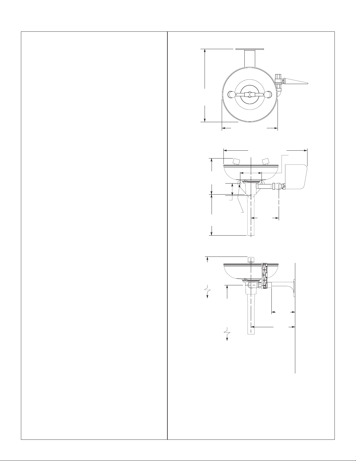
Note : Toutes les dimensions supposent un engagement de
13-1/4"
(337mm)
Ø 10" (254mm)
7-3/8"
(187mm)
2-1/4"
(57mm)
7-1/4"
(184mm)
36" (914mm)
Suggested
hauteur du sol
Height
recommandée
To Floor
Suggested
hauteur du sol
recommandée
Ø 5/16"
(8mm)
30-1/2"
(775mm)
Height
To Floor
15-1/2" (394mm)
5-1/4"
(133mm)
(210mm)
(102mm)
4-1/2"
(114mm)
8-1/4"
4"
Wall
Murale
Figure 1
filetage standard. Les variations de fabrication prévoient
+/- 3,1 mm (1/8”) par joint fileté. Pour trouver la tolérance
d’une dimension, ajouter le nombre de joints filetés entre
une dimension et le multiplier par 3,1 mm (1/8”).
6
2/4/08 Bradley Corporation • 215-158 Rev. W; ECN 08-503
Page 7

Installation S19-220
Assemblage des composantes
1.8
8
1.7
1.6
1.5
1.2
1.1
Drain de sortie
1-1/4" NPT
(1-1/4" NPT)
Drain Outlet
Contrôle du
Flow Control
débit, ce bout
This End
1.4
1.3
2
7
1
1/2" NPT
Approvisionnement à
Supply Inlet
l’entrée (1/2" NPT)
4
3
P.O. BOX 309, MENOMONEE FALLS, WI 53052-0309 USA
TEL: 1-800-BRADLEY FAX: (262-251-5817)
http://www.bradleycorp.com
114-051
9
R
P.O. Box 309, Menomonee Falls, WI 53051
TEST THIS UNIT EACH WEEK
DIESES GERÄT 1ST WÖCHENTLICH ZU PRÜFEN.
ESSAI HEBDOMADAIRE
Test-operate valve(s) each week and sign below.
Report any malfunctions immediately.
Ventil(e) wöchentlich im Testbetrieb prüfen, bestätigt
durch Unterschrift. Jegliche Störung sofort melden.
Test le fonctionnement des valves chaque semaine et
signe en bas. S'il y à quelque chose qui ne va pas fait
un rapport immédiatement.
Date
Signed
Date Signed
Datum
Unterschrift
Date
Signed
Date
Signe
Date
Signed
6
5
4.1
Figure 2
Piéce Réf Qté Description
11 S90-293 1 Assemblage de récepteur, plastique
1.1 111-061 1 Raccordement d’entrée du drain
1.2 124-028 1 Joint d’etanchéité
1.3 154-058 1 Récepteur en plastique
1.4 173-025 1 Filtre à tamis
1.5 S21-071 1 Tige d’alimentation
1.6 113-1185 1 Entretoise
1.7 S05-091 1 Assemblage de cadre
1.8 107-371 2 Bouchon antipoussière
Note : Les éléments 1.1-1.8 arrivent préassemblés comme l’élément 1.
Piéce Réf Qté Description
2 113-006LQ 1 Tuyau 1/2” NPT x 9 cm (3-1/2")
3 169-025 1 Coude
4 S27-282 1 Robinet 1/2" (avec écrou)
4.1 110-215 1 Écrou (seulement)
5 128-135 1 Poignée, plastique
6 142-002DA 1 Rondelle de sécurité
7 269-167 1 Raccord droit de vidange
8 114-051 1 Enseigne de sécurité
9 204-421 1 Etiquette d’inspection
Paquet S45-123 comprend les éléments 4.1, 5, 6
Paquet S45-122 comprend les éléments 4, 4.1, 5, 6
Paquet S45-1785 comprend les éléments 1.2, 1.4, 1.5, 1.6
Bradley Corporation • 215-158 Rev. W; ECN 08-503 2/4/08
7
Page 8

S19-220 Installation
IMPORTANTE
Lea en su totalidad este manual de instalación para garantizar una instalación adecuada.
Installation
THIS
SIDE
UP
Una vez que termine la instalación, entregue este manual al propietario o al Departamento
de Mantenimiento. Es responsabilidad de quien instale el equipo cumplir con los códigos
para desagüe y otra códigos y ordenanzas locales.
Separar todas las piezas del material de embalaje y asegurarse que todas las piezas
Packing List
•
•
•
estén incluídas antes de desechar cualquier material de embalaje. Si faltase alguna pieza,
•
no intentar instalar la unidad combinada Bradley hasta obtener las piezas faltantes.
Aclarar el conducto del suministro de agua antes y después de la instalación. Verificar
que no haya fugas y que el flujo de agua sea adecuado. El suministro principal de agua a
la unidad debe estar siempre en posición “ON” (abierto). Se deben tomar medidas a fin de
evitar el corte no autorizado del suministro.
La norma ANSI Z358.1 exige un suministro ininterrumpido del líquido de enjuague a
una presión mínima de 30 psi (0.21 MPa). El líquido de limpieza debe estar tibio en
conformidad con la norma ANSI Z358.1.
R
1
5
0
3
I 5
W
,
s
ll
a
.
.
N
F
e
E
w
e
F
n
Ü
.
o
R
belo
P
m
o
et
U
n
elden
bestätigt
Z
e
,
H
d sign
C
t m
, M
I
y.
9
L
or
0
K
T
3
E
a pas fait
N
prüfen
iatel
E
x
e semaine
E
d
eek an
H
W
g sof
qu
C
Bo
H
.
me
i ne v
Ö
h w
C
O
E
.
W
A
cha
P
im
R
tbetrieb
törun
E
I
T
s
S
A
T
ns
I
Signed
D
1
Te
N
A
T
he S
alves
hose qu
e(s) eac
U
Signed
Ä
M
ctio
im
R
O
IS
e c
alv
h
E
Signed
D
H
es v
T
B
G
alfun
tlic
E
S
T
t.
E
S
H
I
ent d
S
E
Date
en
y m
hen
T
A
E
I
perate v
c
S
Date
D
ö
S
t an
E
nnem
Date
'il y à quelqu
est-o
T
édiatem
epor
m
R
Ventil(e) w
t im
r
durch Unterschrift. Jeglic
e en bas. S
Signed
Test le fonctio
Unterschrift
rappo
sign
Signe
un
Date
Datum
Date
Este equipo se debe inspeccionar, probar y anotar semanalmente para mantener un
funcionamiento adecuado
. Se debe revisar este equipo anualmente para asegurarse de
que cumpla con la norma ANSI Z358.1.
Los trabajadores que puedan tener contacto con materiales potencialmente peligrosos
deben recibir capacitación sobre la ubicación y operación adecuada de los equipos de
P.O. BOX 309, MENOMONEE FALLS, WI 53052-0309 USA
TEL: 1-800-BRADLEY FAX: (262-251-5817)
http://www.bradleycorp.com
114-051
emergencia en conformidad con la norma ANSI Z358.1.
Para consultas sobre la operación o instalación de este producto, visite www.bradleycorp.
com o llame al 1-800-BRADLEY.
Las garantías del producto se pueden encontrar e n “Información del producto” o en
nuestro sitio Web, www.bradleycorp.com.
8
2/4/08 Bradley Corporation • 215-158 Rev. W; ECN 08-503
Page 9
Installation S19-220
Instalación
Materiales necesarios:
• 3 soportes de pared y pernos de 3/8”
• Sellador de tubos
• Tubería para la entrada de 1/2 NPT de suministro
de agua a la unidad
• Tubería para la salida de 1-1/4 NPT para el lavador
de ojos
• Tornillería para montar el aviso de seguridad
Nota: Los códigos locales pueden exigir la instalación
de una válvula de prevención de contrafl ujo para
completar la instalación correcta. La conformidad
con los códigos locales es de responsabilidad del
instalador. La válvula se debe probar anualmente
para verifi car que funcione de manera correcta.
Las válvulas de prevención de contrafl ujo no se
incluyen con el accesorio y las puede proporcionar
el contratista o las puede comprar en Bradley
Corporation.
13-1/4"
(337mm)
Ø 10" (254mm)
15-1/2" (394mm)
4"
(102mm)
Paso 1: Instale el accesorio de entrada del
drenado
Nota: La parte superior de los rociadores deben
quedar a 33”–45” (838mm–1143mm) del piso.
1. Coloque el accesorio de entrada del drenado
sobre el tubo de salida de drenado de 1-1/4
NPT (saliendo de la pared).
2. Usando el accesorio de entrada del drenado
como plantilla, marque los orificios para
ubicación de los pernos en la pared O instale
tres soportes de pared (proporcionados por
el instalador) para pernos de 3/8” en la pared,
en los lugares marcados para los orificios (vea
Figura 1).
3. Fije el accesorio de entrada de drenado a la
pared o fíjelo en la pared usando los soportes
de pared y pernos de 3/8” (proporcionados por
el instalador).
Paso 2: Armado de los componentes del
lavador de ojos
1. Arme los componentes restantes del lavador de
ojos como se indica en la Figura 2 (pagina 10).
• Aplique sellador de tubos (proporcionado
por el instalador) a todas las uniones de los
tubos macho roscados.
• Use una llave de cinta para apretar los tubos
y evitar que se dañen.
Paso 3: Conecte el suministro de agua
1. Conecte la tubería de suministro de agua a la
entrada de 1/2 NPT en el lavador de ojos (la
tubería es proporcionada por el instalador).
2. Conecte la pieza inferior a la salida de drenado
de 1-1/4 NPT en el lavador de ojos.
3. Fije el aviso de seguridad a la pared, usando
tornillería adecuada (proporcionada por el
instalador).
4. Abra las líneas del suministro de agua. Revise
que no haya fugas y que el flujo de agua sea
adecuado.
7-3/8"
(187mm)
2-1/4"
(57mm)
Ø 5/16"
7-1/4"
(184mm)
36" (914mm)
Suggested
de altura desde
Height
el piso
To Floor
recomendada
(8mm)
30-1/2"
(775mm)
Suggested
de altura desde
Height
el piso
recomendada
To Floor
Figura 1
NOTA: Todas las dimensiones asumen el enganche de rosca
estándar. Las variaciones en la fabricación permiten +/- 3,1
mm (1/8”) por junta roscada. Para encontrar la tolerancia
de una dimensión, agregue el número de juntas roscadas
entre una dimensión y multiplíquelo por 3,1 mm (1/8”).
5-1/4"
(133mm)
4-1/2"
(114mm)
8-1/4"
(210mm)
Wall
Pared
Bradley Corporation • 215-158 Rev. W; ECN 08-503 2/4/08
9
Page 10

S19-220 Installation
Armado de los componentes
1.8
8
1.7
1.6
1.5
1.2
1.1
Salida de drenado
1-1/4" NPT
(1-1/4" NPT)
Drain Outlet
Control del flujo
Flow Control
en este extremo
This End
1.4
1.3
2
7
1
1/2" NPT
Entrada de suministro
Supply Inlet
(1/2" NPT)
4
3
5
114-051
P.O. BOX 309, MENOMONEE FALLS, WI 53052-0309 USA
TEL: 1-800-BRADLEY FAX: (262-251-5817)
http://www.bradleycorp.com
P.O. Box 309, Menomonee Falls, WI 53051
TEST THIS UNIT EACH WEEK
DIESES GERÄT 1ST WÖCHENTLICH ZU PRÜFEN.
ESSAI HEBDOMADAIRE
Test-operate valve(s) each week and sign below.
Report any malfunctions immediately.
Ventil(e) wöchentlich im Testbetrieb prüfen, bestätigt
durch Unterschrift. Jegliche Störung sofort melden.
Test le fonctionnement des valves chaque semaine et
signe en bas. S'il y à quelque chose qui ne va pas fait
un rapport immédiatement.
Date
Signed
Date Signed
Datum
Unterschrift
Date
Date
Signe
Date
4.1
9
R
Signed
Signed
6
Figura 2
Art. Pieza N° Cant. Descripción
11 S90-293 1 Conjunto del recipiente, plastico
1.1 111-061 1 Acceso de entrada de drenado
1.2 124-028 1 Empaque
1.3 154-058 1 Recipiente de plastico
1.4 173-025 1 Filtro de copa
1.5 S21-071 1 Accessorio de suministro
1.6 113-1185 1 Espaciador
1.7 S05-091 1 Conjunto de horquilla
1.8 107-371 2 Cubierta guardapolvo
Paquete S45-123 incluye art. 4.1, 5, 6
Paquete S45-122 incluye art. 4, 4.1, 5, 6
Paquete S45-1785 incluye art. 1.2, 1.4, 1.5, 1.6
10
2/4/08 Bradley Corporation • 215-158 Rev. W; ECN 08-503
Nota: Las piezas 1.1-1.8 vienen preensambladas como Artículo 1.
Art. Pieza N° Cant. Descripción
2 113-006LQ 1 Tubo de 1/2” NPT x 9 (cm) 3-1/2
3 169-025 1 Codo
4 S27-282 1 Valvula de bola de 1/2” (con tuerca)
4.1 110-215 1 Tuerca (solamente)
5 128-135 1 Manilla, plastico
6 142-002DA 1 Arandela de seguridad
7 269-167 1 Pieza inferior
8 114-051 1 Aviso de seguridad
9 204-421 1 Etiqueta de inspeccion
 Loading...