

Page 1
P.O. Box 309, Menomonee Falls, WI USA 53052-0309
PHONE 1-800-BRADLEY FAX (262) 251-5817
http://www.bradleycorp.com
Installation
215-163DCE Rev. Z; EN 06-532F
© 2007 Bradley Corporation
Page 1 of 5 6/25/07
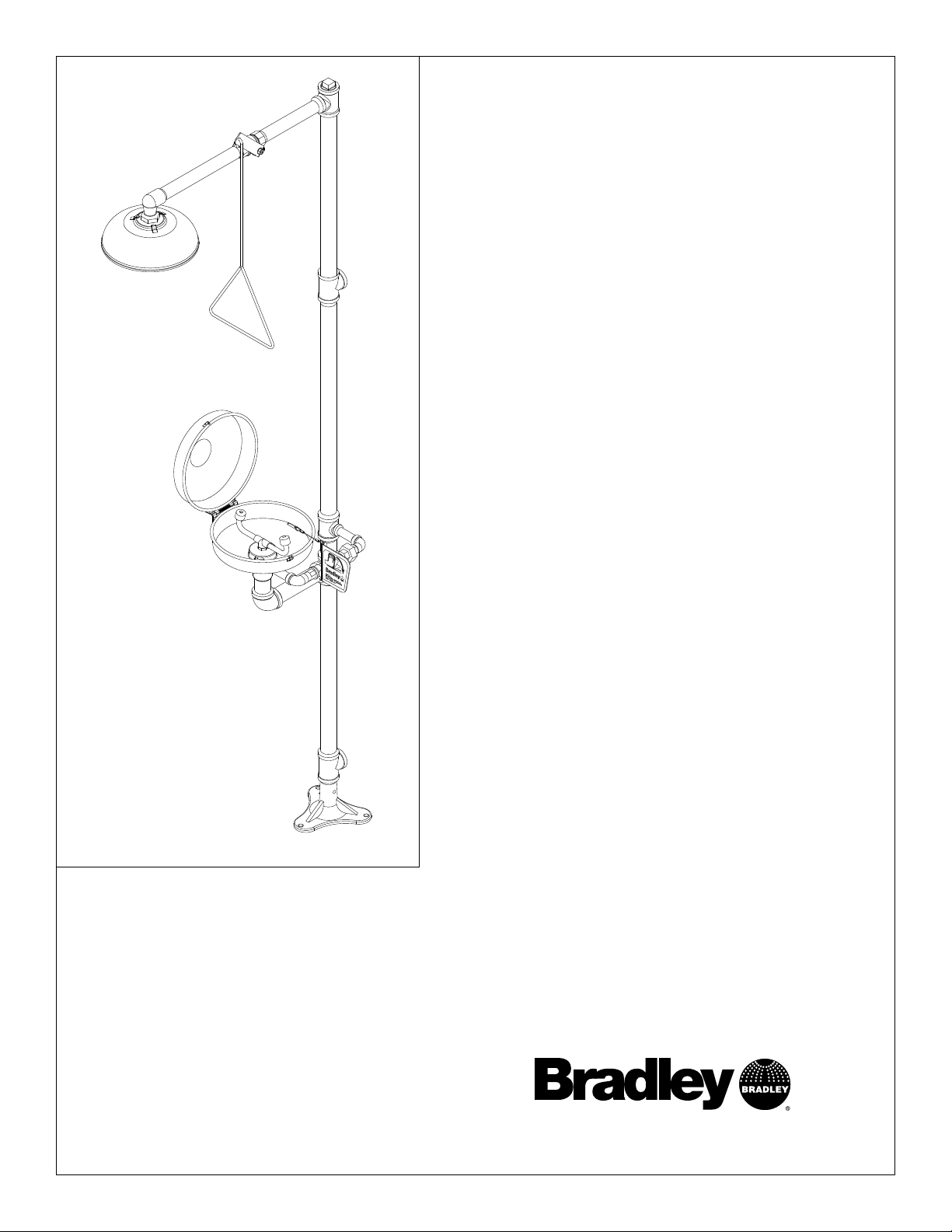
E19-310DC
Combination Drench Shower/Eyewash
Table of Contents
Pre-Installation Information . . . . . . . . . . . . . . . . . .2
Installation Instructions . . . . . . . . . . . . . . . . . . . . . .3
Assembly of Components . . . . . . . . . . . . . . . . . . . .4
Parts List . . . . . . . . . . . . . . . . . . . . . . . . . . . . . . . . .5
Page 2
2
E19-310DC Installation
6/25/07 Bradley Corporation • 215-163DCE Rev. Z; EN 06-532F
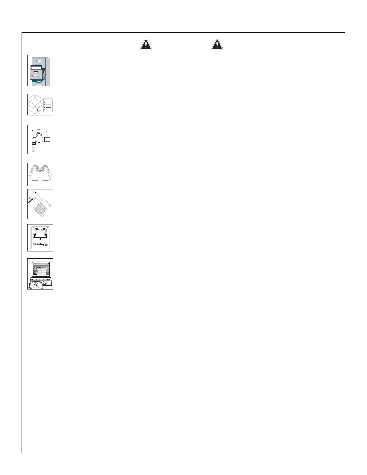
WARNING
Read this installation manual completely to ensure proper installation, then file it
with the owner or maintenance department. Compliance and conformity to drain
requirements and other local codes and ordinances is the responsibility of the
installer.
Separate parts from packaging and make sure all parts are accounted for before
discarding any packaging material. If any parts are missing, do not begin
installation until you obtain the missing parts.
Flush the water supply lines before beginning installation and after installation is
complete. Test the unit for leaks and adequate water flow. Main water supply to
the eyewash should be “ON” at all times. Provisions shall be made to prevent
unauthorized shutoff.
The ANSI Z358.1 standard requires an uninterruptible supply of flushing fluid at a
minimum 30 PSI (0.21 MPa) flowing pressure. Flushing fluid should be tepid per
ANSI Z358.1.
The inspection and testing results of this equipment should be recorded weekly
to verify proper operation. This equipment should be inspected annually to
ensure compliance with ANSI Z358.1.
Workers who may come in contact with potentially hazardous materials should be
trained regarding the placement and proper operation of emergency equipment
per ANSI Z358.1.
For questions regarding the operation or installation of this product, visit
www.bradleycorp.com or call 1-800-BRADLEY.
Product warranties may also be found under ”Product Information” on our web
site at www.bradleycorp.com.
Installation
T
H
IS
S
ID
E
U
P
Packing List
!
!
!
!
P
.O
. B
o
x
3
0
9
, M
e
n
o
m
o
n
e
e
F
a
lls
, W
I 5
3
0
5
1
R
T
E
S
T
T
H
I
S
U
N
I
T
E
A
C
H
W
E
E
K
Test-operate valve(s) each week and sign below
.
R
eport any m
alfunctions imm
ediately.
Ven
til(e) w
öche
ntlich im
Testbe
trieb prüfen
, bestätig
t
durch U
ntersch
rift. Jeg
liche Störung sofort m
eld
en.
Date
Datum
Date
Signed
Unterschrift
Signe
Date
Date
Date Signed
Signed
Signed
D
I
E
S
E
S
G
E
R
Ä
T
1
S
T
W
Ö
C
H
E
N
T
L
I
C
H
Z
U
P
R
Ü
F
E
N
.
E
S
S
A
I
H
E
B
D
O
M
A
D
A
I
R
E
Test le fonctionnem
ent des va
lves chaque se
m
ain
e et
signe en bas. S
'il y à quelque chose q
u
i ne va pas fait
un rapport im
médiatem
ent.
P.O. BOX 309, MENOMONEE FALLS, WI 53052-0309 USA
TEL: 1-800-BRADLEY FAX: (262-251-5817)
http://www.bradleycorp.com
114-051
Page 3

3
Installation E19-310DC
Bradley Corporation • 215-163DCE Rev. Z; EN 06-532F 6/25/07
Installation
Supplies Required:
• (3) M10 floor anchors and bolts
• Teflon tape and pipe sealant
• Piping to 1-1/4" BSP water supply inlet on unit
• Adequate supply pipe supports
• Piping to 1-1/4" BSP drain outlet for eyewash
• Minimum 102mm (4") drain to accommodate
115 liters (30 gallons) per minute discharge for
shower waste
• OPTIONAL: sign-mounting hardware
Step 1: Secure base to floor
1. Install three suitable anchors (by installer)
for M10 bolts in the floor (see Figure 1).
2. Bolt the base to the floor anchors using M10
bolts (supplied by installer).
IMPORTANT: Some teflon sealants
may cause stress cracks in the plastic
showerhead leading to failure. Use
teflon tape for sealing the showerhead.
Step 2: Assemble eyewash components
1. Assemble the remaining unit components as
shown in Figure 2 on page 4.
• Apply pipe sealant (supplied by installer) to
all male-threaded pipe joints.
• Use the rubber grip pad provided or a strap
wrench around pipes when tightening to
prevent marring. Place the grip pad on the
pipe, then put the wrench over the grip pad
and turn the pipe with the wrench.
• Bottom edge of showerhead should be
2160mm (7'-1") from floor.
Step 3: Connect water supply
IMPORTANT: Do not rely on Bradley’s
Combination Unit to support supply
piping.
1. Connect water supply piping to 1-1/4" BSP
inlet on unit (piping supplied by installer).
Provide adequate supports (supplied by
installer) for supply pipe using pipe hangers or other means.
2. Connect drain piping to 1-1/4" BSP drain outlet on unit (piping supplied by installer).
3. Hang the safety sign from the unit with the curtain hooks provided (or mount it to the wall using
sign-mounting hardware supplied by installer).
Figure 1
NOTE: All dimensions assume standard thread
engagement. Variations in manufacturing allow
for +/- 1/8" (3mm) per threaded joint. To find
the tolerance of a dimension, add the number
of thread joints in between a dimension and
multiply it by 1/8" (3mm).
Ø 273mm
(10-3/4")
247mm
(9-3/4")
with (3) Ø 10mm (3/8")
Holes on Ø 203mm (8")
267mm
(10-1/2")
Use Teflon
Tape Only
645mm
133mm
(5-1/4")
Ø 254mm
(10")
2160mm
(7'-1")
To
Floor
(25-3/8")
229mm
(9")
610mm
(24")
152mm
(6")
Ø 229mm (9") Flange
Bolt Circle
140mm
(5-1/2")
1041mm
(41")
1676mm
(66")
To
Floor
Page 4

Assembly of Components
4
E19-310DC Installation
6/25/07 Bradley Corporation • 215-163DCE Rev. Z; EN 06-532F
NOTE: Items 4.1–4.12 come preassembled as Item 4.
Items 9.1–9.5 come preassembled as Item 9.
Items 14.1–14.3 come preassembled as Item 14.
Figure 2
NOTE: If tee (Item 7) is used as a supply
7
inlet, use plug (Item 7) on tee (Item 2).
BSP threads this end
12
14.3
11
14.1
14.2
9.1
13
NOTE: Use
teflon tape
only.
P.O. BOX 309, MENOMONEE FALLS, WI 53052-0309 USA
TEL: 1-800-BRADLEY FAX: (262-251-5817)
http://www.bradleycorp.com
114-052
9
8
9.2
6
2
5
1-1/4" BSP Supply Inlet
(BSP threads are noted
with black line on threads)
19
9.3
9.4
9.5
9.11
Flow
Control
This End
15.4
15.3
5
15.2
14
10
18
17
16
15.1
4.4
4.2
4.7
4.3
4.12
4.11
4.6
4.5
4.71
22
4.1
4
4.10
4.12
4.2
4.8
4.9
P.O. Box 309, Menomonee Falls, WI 53051
TEST THIS UNIT EACH WEEK
DIESES GERÄT 1ST WÖCHENTLICH ZU PRÜFEN.
ESSAI HEBDOMADAIRE
Test-operate valve(s) each week and sign below.
Report any malfunctions immediately.
Ventil(e) wöchentlich im Testbetrieb prüfen, bestätigt
durch Unterschrift. Jegliche Störung sofort melden.
Test le fonctionnement des valves chaque semaine et
signe en bas. S'il y à quelque chose qui ne va pas fait
un rapport immédiatement.
Date
Signed
Date Signed
Datum
Unterschrift
Date
Date
Signe
Date
HANDLE NOTE:
23
R
Signed
Signed
3
Close the cover
and put the pin
through the clip
to keep closed.
21
20
2
1-1/4" BSP
Drain Outlet
1
Page 5

5
Installation E19-310DC
Bradley Corporation • 215-163DCE Rev. Z; EN 06-532F 6/25/07
Parts List
1 131-059 1 Base
2 169-727B 2 Pipe Tee 1-1/4" NPT
3 113-006LC 1 Pipe 1-1/4" NPT x 706 mm
4 S39-226 1 Europe Eyewash Sub-Assy.
4.1 111-039 1 Inlet Drain Fitting
4.2 169-025 2 Street Elbow
4.3 S06-136 1 Plgd. Nipple 1-1/4" NPT x 76mm
4.4 169-841 1 Reducing Tee
4.5 142-002DA 1 Lockwasher
4.6 169-726 1 Union 1/2" Female NPT
4.7 S27-282 1 1/2" Ball Valve with Nut
4.71 110-215 1 Jam Nut only
4.8 113-006QX 1 Pipe 1-1/4" NPT x 180mm
4.9 169-764 1 90° Pipe Elbow 1-1/4" NPT
4.10 113-006LE 1 Pipe Nipple 1-1/4" NPT x 76mm
4.11 169-727 1 PIpe Tee 1-1/4" NPT
4.12 113-006LQ 3 Pipe 1/2" NPT x 76mm
5 113-006LW 2 Pipe 1-1/4" NPT x 579 mm
6 169-722B 1 Reducing Tee
7 169-724 1 Pipe Plug 1-1/4" NPT
8 113-006LL 1 Pipe 1" NPT x 234 mm
9 S30-059 1 Stay-Open Ball Valve 1" NPT
9.1 S27-278 1 1" Ball Valve with Jam Nut
9.11 110-214 1 Jam Nut only
9.2 140-720 1 Stop Bracket
9.3 124-048 1 Washer, Friction
9.4 128-129 1 Handle
9.5 142-002DC 1 Lockwasher
10 128-156A 1 Pull Rod - 24" Long
11 113-006LK 1 Pipe 1" NPT x 310 mm
12 169-723 1 90° Street Elbow 1" NPT
13 151-001 2 Curtain Hook
14 S24-070 1 Showerhead Assembly
14.1 154-057 1 Showerhead Shell
14.2 155-005 1 Diffuser
14.3 160-245 3 Screw
15 S45-1782 1 Cup Strainer Prepack
15.1 124-028 1 Center Seal Gasket
15.2 173-009 1 Cup Strainer
15.3 S21-071 1 Stem Pipe Assembly
15.4 113-1159 1 Spacer, Drain
16 S90-009 1 Dust Cover Assembly
17 269-447 1 Bumper
18 161-025 1 Nut
19 S05-091 1 Eyewash Yoke
20 S08-056 1 Handle Assembly
21 153-372R 1 Adapter
22 204-421 1 Emergency Tag
23 114-052E 1 Safety Sign
24 269-915 1 Grip Pad (not shown)
Item Part No. Qty Description
Item Part No. Qty Description
Prepack S30-087 includes Items 4.71, 4.5, 20
 Loading...