

Page 1
215-1485 Rev. G; EN 09-00-0019
©2009 Bradley Corporation
Page 1 of 22 11/5/2009
P.O. Box 309, Menomonee Falls, WI 53052-0309
TEL. 1-800-Bradley FAX 262-251-5817
http://www.bradleycorp.com
Parts & Service Guide
Multi-Fount Washfountains
Terrazzo Models
DISCONTINUED MODELS
PRIOR TO MAY 7, 2007
Call for Parts Availability
Page 2

2 Bradley Corporation • 215-1485 Rev. G; EN 09-00-0019
11/5/2009
Te rrazzo Multi-Fount Washfountains Parts and Service Guide
Table of Contents
Washfountain Identification Page #
Identification Chart and Model Numbers . . . . . . . . . . . . . . . . . . . . . . . . . . . . . . . . . . . . . . . . . . . . . . .3
Terrazzo Multi-Fount Washfountains
Infrared (IR) — Sprayhead Infrared and Streamformer Parts . . . . . . . . . . . . . . . . . . . . . . . . . . . . . . .4
Infrared (IR) — Replacing Parts . . . . . . . . . . . . . . . . . . . . . . . . . . . . . . . . . . . . . . . . . . . . . . . . . . . . . .5
Infrared (IR) — Solenoid Valve Assembly and 24V plug-in transformer . . . . . . . . . . . . . . . . . . . . . .6
Infrared (IR) — Solenoid Valve S07-040 Individual (End), S07-041 Ganged . . . . . . . . . . . . . . . . . . .7
Infrared (IR)— Sensor and Valve Troubleshooting . . . . . . . . . . . . . . . . . . . . . . . . . . . . . . . . . . . . . . .8
90-75 — Sprayhead 90-75 and Streaformer Parts . . . . . . . . . . . . . . . . . . . . . . . . . . . . . . . . . . . . . .9-10
90-75 — Metering Valve Repair Kit S65-084 . . . . . . . . . . . . . . . . . . . . . . . . . . . . . . . . . . . . . . . . . .10
90-75 — Metering Valve Timing Adjustments . . . . . . . . . . . . . . . . . . . . . . . . . . . . . . . . . . . . . . . . . .11
90-75 — Metering Valve Troubleshooting Instructions . . . . . . . . . . . . . . . . . . . . . . . . . . . . . . . . . . .12
90-75 — Cartridge Replacement . . . . . . . . . . . . . . . . . . . . . . . . . . . . . . . . . . . . . . . . . . . . . . . . . . . . .13
Supply and Mixing Valve . . . . . . . . . . . . . . . . . . . . . . . . . . . . . . . . . . . . . . . . . . . . . . . . . . . . . . . . . .14
Vernatherm
®
Thermostatic Mixing Valve S01-116B . . . . . . . . . . . . . . . . . . . . . . . . . . . . . . . . . . . . . .15
Soap System . . . . . . . . . . . . . . . . . . . . . . . . . . . . . . . . . . . . . . . . . . . . . . . . . . . . . . . . . . . . . . . . . .16-18
Drain Spud and Strainer . . . . . . . . . . . . . . . . . . . . . . . . . . . . . . . . . . . . . . . . . . . . . . . . . . . . . . . . . . .19
Pedestal Assembly . . . . . . . . . . . . . . . . . . . . . . . . . . . . . . . . . . . . . . . . . . . . . . . . . . . . . . . . . . . . . . . .20
Replacement Pedestal Panels . . . . . . . . . . . . . . . . . . . . . . . . . . . . . . . . . . . . . . . . . . . . . . . . . . . . . . . .21
Maintenance Instructions . . . . . . . . . . . . . . . . . . . . . . . . . . . . . . . . . . . . . . . . . . . . . . . . . . . . . . . . . . .22
Part numbers are subject to change without formal notice.
Page 3
Parts and Service Guide Terrazzo Multi-Fount Washfountains
Bradley Corporation • 215-1485 Rev. G; EN 09-00-0019 3
11/5/2009
• Highly Vandal Resistant
• Saves Water, Energy, and Space
• Available with 90-75 Metering or Infrared Control
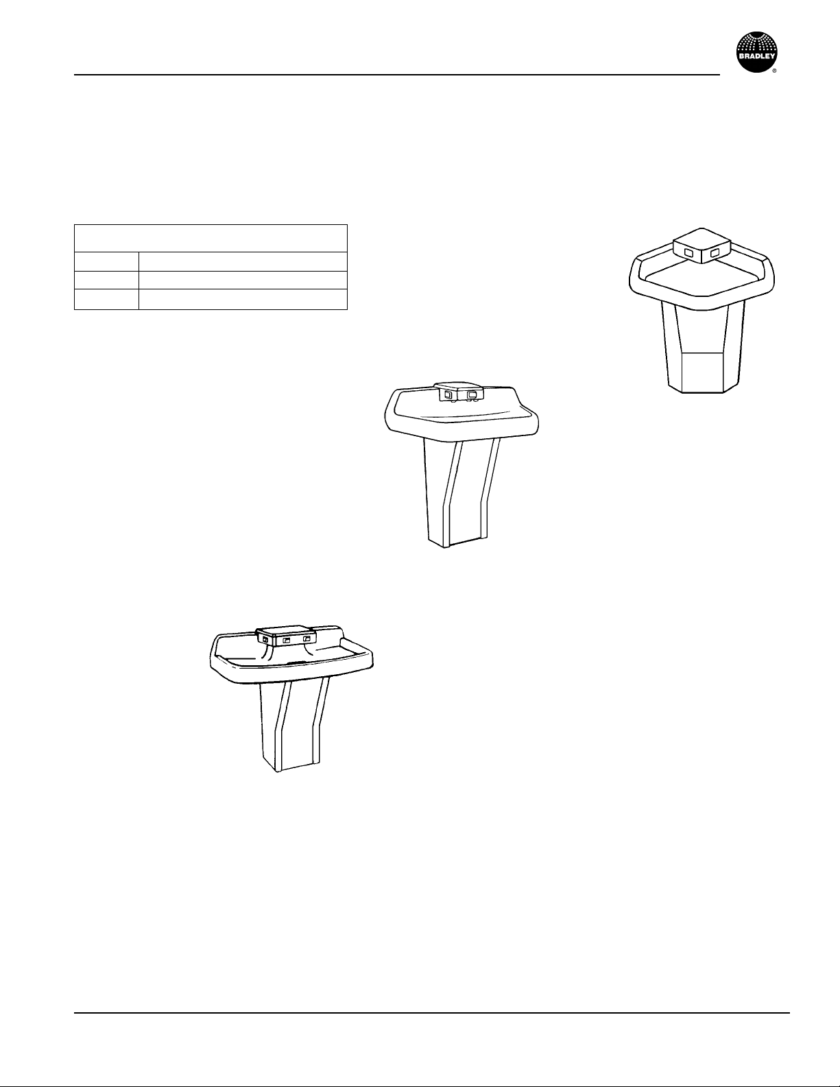
Models Available:
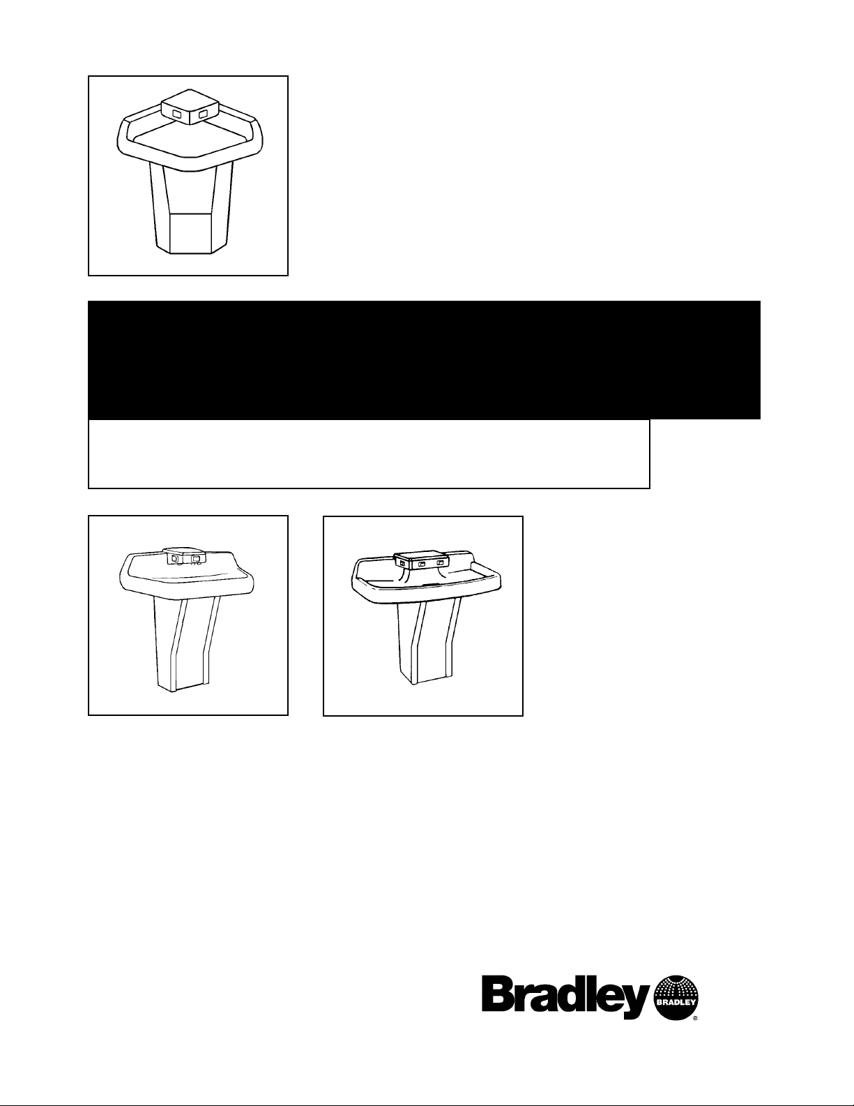
MF2902 Terrazzo Corner-Fount
MF2903 Terrazzo Tri-Fount
MF2904 Terrazzo Quadra-Fount
Terrazzo Multi-Fount Washfountains
MF2902
Infrared Shown (IR)
MF2903
Metering Valve Shown (90-75)
MF2904
Metering Valve Shown (90-75)
Page 4

Terrazzo Multi-Fount Washfountains Parts and Service Guide
4 Bradley Corporation • 215-1485 Rev. G; EN 09-00-0019
11/5/2009
Infrared (IR) — Sprayhead Infrared and Streamformer Parts
Corner Tri Quad
Item Part No. Description Qty Qty Qty
1 269-508 Sprayhead Diffuser MF 4 6 8
2 125-001EG O-Ring — — —
3 115-125 Streamformer 2 6 8
4 160-246 Screw 8-32 X 3/4, Oval Head 2 6 8
Parts List — Streamformer Assembly
Corner Tri Quad
Item Part No. Description Qty Qty Qty
1 269-382 Coupling Nut - Quick Disconnect 4 6 8
2 S65-107 Multi-Fount Sensor Repair kit (269-1184 w/o connectors) — — —
3 124-070 Gasket, MF Window Terrazzo 2 6 8
4 269-604 Window, IR MF Terrazzo 2 3 4
5 S53-127 Window Plate, IR MF Terrazzo 2 3 4
6 135-049 Spring, Window Plate 2 6 8
7 160-246 Screw 1/4-20 X 3/8, Set SC 18-8 SS 2 6 8
* 269-621 Female Connector (3 required per 269-1184) 6 9 12
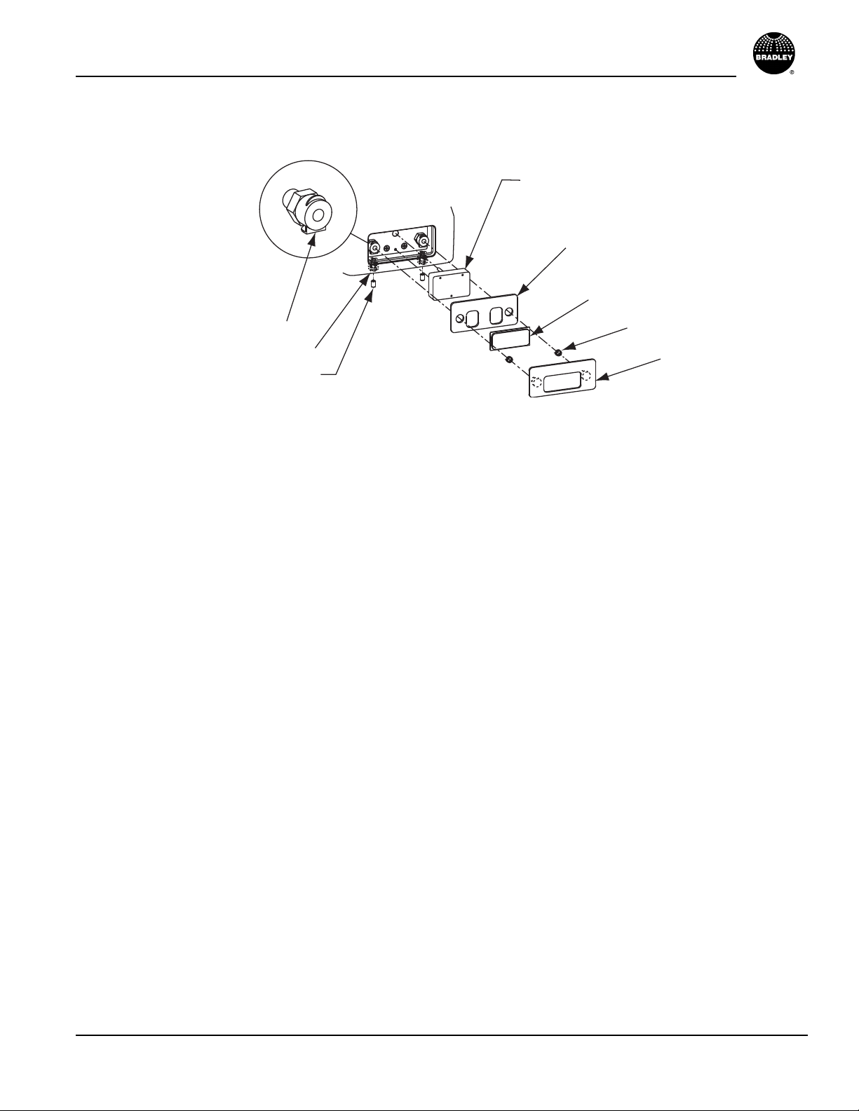
Parts List — Infrared Sensor and Sprayhead Assembly
Infrared Sensor Streamformer (Aerator)
Side View of Sprayhead
* Not Illustrated.
1
7
6
5
2
3
4
4
1
2
3
Page 5
Parts and Service Guide Terrazzo Multi-Fount Washfountains
Bradley Corporation • 215-1485 Rev. G; EN 09-00-0019 5
11/5/2009
Infrared (IR) — Replacing Parts
To Change the Sensor or Window:
1. Use an 1/8" allen wrench to remove the window release set screws (Item 7), located under the
sprayhead. This allows access to the release holes under the sensor.
2. The “Spring Clip Lever” gets pushed in to release the sensor assembly from the sprayhead.
Push the allen wrench up into release holes to push on the spring clip lever on the quick disconnect coupling nut (Item 1). This lever will click and lock in the open position to allow removal
of the window and sensor.
3. Remove the sensor window plate, window and gasket.
4. Loosen the three screws holding the sensor in place.
5. Cut the insulated terminals off the sensor cable and remove the sensor.
To Reinstall the Sensor or Window:
1. Insert the replacement sensor cable into the cavity and feed thru to the pedestal.
2. From the pedestal below, pull on the sensor cable to pull the remaining cable through.
3. Install and tighten the three sensor screws.
4. Connect the sensor cable terminals.
5. Before reinstalling the window plate, window and gasket, make sure the spring clip lever on the
quick release body is pushed in (open). This lever will click and lock in the open position.
6. Position the window gasket over the sensor making sure the sensor eyes align to the gasket holes.
7. Insert the window into the window plate assembly and insert the assembly pins through the gasket. Press firmly on the outer edge of the plate assembly until it clicks (locks) into position.
8. Reinstall the window release set screws on the underside of the sprayhead.
Sensor ( Three Captive Screws)
Gasket
Window
Spring Clip Lever
Release Hole
Window Release Set Screw
Spring
Window Plate
Page 6
Terrazzo Multi-Fount Washfountains Parts and Service Guide
6 Bradley Corporation • 215-1485 Rev. G; EN 09-00-0019
11/5/2009
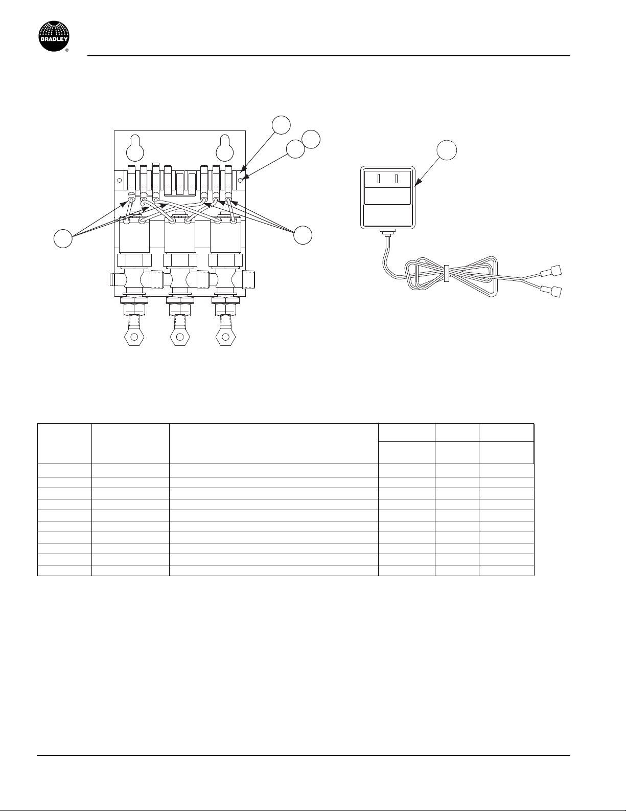
Infrared (IR) — Solenoid Valve Assembly and 24V Plug-in Transformer
Corner Tri Quad
Item Part No. Description Qty Qty Qty
* S08-341 2 Valve Assy. With Bracket 1 — —
Fig. A S08-298 3 Valve Assy. With Bracket — 1 —
* S08-299 4 Valve Assy. With Bracket — — 1
1 269-625 Terminal Block (2 or 3 valve) 1 1 —
1 269-647 Terminal Block (4 valve) — — 1
2 160-329 Screw 6-32X3/8 Rd. Hd. 2 2 2
3 161-069 Nut 6-32 Lock 2 2 2
4 S53-129 Wire Assy. Red 2 3 4
5 S53-128 Wire Assy. Black 2 3 4
6 S83-134 Transformer 24VAC (269-901 w/o connectors) 1 1 1
Parts List — Solenoid Assembly
* Not Illustrated.
Figure A
1
3
2
6
5
4
Page 7
Parts and Service Guide Terrazzo Multi-Fount Washfountains
Bradley Corporation • 215-1485 Rev. G; EN 09-00-0019 7
11/5/2009
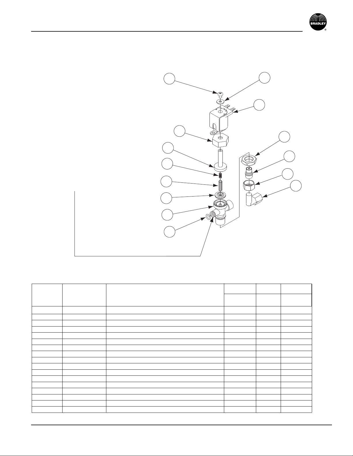
Infrared (IR) — Solenoid Valve S07-040 Individual (End),
S07-041 Ganged
S07-040 Solenoid Valve (Individual)
Used by itself, or is the last one (opposite
end of the water inlet) in a group.
S07-041 Solenoid Valve (Ganged)
Used in a group, except the last in
line. Body is drilled to allow water to
pass thru into the next in line. This
valve includes O-Ring 125-145 to
seal to the next valve.
8
9
7
11
10
14
15
12
16
13
19
20
17
18
Figure B
Corner Tri Quad
Item Part No. Description Qty Qty Qty
Fig. B S07-040 Valve Individual 1 1 1
Fig .B S07-041 Valve Ganged 1 2 3
7 160-066 Screw 10-24X1/4 Rd. Hd. 2 3 4
8 124-002AZ Washer Stainless Steel 2 3 4
9 269-579 Coil - Solenoid Valve 2 3 4
10 110-094 Nut - Bonnet 2 3 4
11 121-028 Bonnet 2 3 4
12 269-578 Spring 2 3 4
13 269-577 Armature 2 3 4
14 269-580 Diaphragm 2 3 4
15 118-237 Valve Body Individual 1 1 1
15 118-238 Valve Body Ganged 1 2 3
16 125-145 O-Ring (for ganged valve body only) 1 2 3
17 110-224 Nut 3/8-18 Hex Brass 2 3 4
18 S88-065 Tailpiece Assembly 2 3 4
19 110-195 Tailpiece Nut 2 3 4
20 145-090 Elbow 2 3 4
Parts List — Solenoid Valve Parts
Page 8

Terrazzo Multi-Fount Washfountains Parts and Service Guide
8 Bradley Corporation • 215-1485 Rev. G; EN 09-00-0019
11/5/2009
Infrared (IR) — Sensor and Valve Troubleshooting
If a station is not functioning properly it is most likely either the solenoid valve or the sensor.
Troubleshooting multi station units is fairly easy, as you can swap parts (actually just by changing the wires) and use
the process of elimination to figure out which of the 2 parts is causing the problem.
How the system operates:
1. The transformer sends 24 volts to the sensor.
2. The sensor acts only as a switch.
3. When hands go into the active field of the sensor, the sensor activates and sends a power signal
on to the solenoid valve.
4. The power signal activates and opens the solenoid valve which allows the water to flow to the
sprayhead. The solenoid valve stays open allowing water to flow as long as it is receiving a
signal form the sensor (hands remain in the active field).
5. When hands are removed from the active field, the sensor turns off (note some models have a
slight delay feature built-in.) and shuts off the power signal to the solenoid valve.
Note: The solenoid valves will be in-line and will be in the same order as the stations (in other words the
center solenoid will operate the center station, the right solenoid will operate the right station).
Complaint:
The center station will not shut off.
1. Disconnect the sensor wires to the center solenoid valve and set them out of the way.
2. Disconnect the sensor wires to the left solenoid valve. Set these wires out of way and make
sure they will not make contact with each other or any metal or framework.
3. Connect the wires from the center solenoid valve and connect them to the left solenoid valve.
4. Reconnect the transformer to the wall outlet for power.
5. Use your hands to activate the center station and watch for the water to come out at the left station.
Conclusion:
If the left station works and shuts off, then we know that the solenoid is the problem in the center
station.
If the left station does not shut off, then we know it is the sensor in the center station that is
causing the problem.
Solution:
If the Sensor
is the Problem it will have to be replaced. It cannot be repaired or adjusted in any way.
If the Solenoid
Valve is the Problem it is most likely due to debris between the valve seat and diaphragm. This
happens frequently in new and recent plumbing installations.
Take the solenoid valve apart and clean. Disconnect the wires from the solenoid. Loosen and remove the screw on
top of the coil of the solenoid valve. Unscrew the bonnet nut (counterclockwise) and tip forward to remove from the
valve body. Remove the diaphragm (269-580). Remove any
particles that may have been trapped between the diaphragm and the valve seat. Rinse off the diaphragm and inspect
for damage. Make sure both orifices in the diaphragm are open.
Reassemble and retry the solenoid valve. If there is still a problem, replace the solenoid valve.
If ordering replacement solenoid valves, be careful to order correctly, either an “individual” or a “ganged” solenoid
valve.
Page 9

Parts and Service Guide Terrazzo Multi-Fount Washfountains
Bradley Corporation • 215-1485 Rev. G; EN 09-00-0019 9
11/5/2009
90-75 — Sprayhead 90-75 and Streamformer Parts
Corner Tri Quad
Item Part No. Description Qty Qty Qty
1 P10-132 Screw 8-32X1/2, Phillips Flat Head 4 6 8
2 124-047 Washer, Flat Compressed Foam 2 3 4
3 135-054 Spring, Pushbutton 4 6 8
4 269-186 Pushbutton, Multi-Fount 2 3 4
5 160-300 Screw, Set (Pushbutton) 2 3 4
** 6 S65-084 Repair Kit - Multi-Fount (replacement cartridge) — — —
7 150-116 Celcon Flange 90-75 MF 2 3 4
* 8 S65-067 Pushbutton Service Kit MF (Includes Items 3,4,& 5) — — —
Parts List — 90-75 Valve Assembly
* Not Illustrated.
** See following page for breakdown.
Infrared Sensor
Streamformer (Aerator)
Corner Tri Quad
Item Part No. Description Qty Qty Qty
1 269-508 Sprayhead Diffuser MF 4 6 8
2 125-001EG O-Ring — — —
3 115-125 Streamformer 2 6 8
4 160-246 Screw 8-32 X 3/4, Oval Head 2 6 8
Parts List — Streamformer Assembly
Side View of Sprayhead
1
2
1
3
7
6
4
5
1
2
3
4
Page 10

Terrazzo Multi-Fount Washfountains Parts and Service Guide
10 Bradley Corporation • 215-1485 Rev. G; EN 09-00-0019
11/5/2009
Parts List — Metering Valve S65-084
90-75 — Metering Valve Repair Kit S65-084
1 124-047 1 Soap Guard Washer
2 S73-043 1 Upper Valve Body Assembly
3 135-033 1 Spring
4 S64-089 1 Plunger Assembly
5 125-001DD 1 O-Ring
6 S73-031 1 Lower Valve Body Assembly
7 156-010 1 Filter Disk
Item Part No. Qty Description
1
2
3
4
6
7
5
For areas with poor water quality, use S65-116 mega orifice cartridge. Use the mega orifice cartridge if
you have frequent “won’t turn off” complaints. Poor water quality will cause mineral build-up in the valve
which will restrict the flow and proper operation of the valve.
Note: The standard cartridge provides a 10-12 second timing cycle. The mega orifice
cartridge provides only a 5-7 second timing cycle. The standard cartridge can be changed
to the mega orifice by changing the plunger in the standard cartridge to the S65-091
plunger.
Note: The shorter cycle time of the mega orifice cartridge is not acceptable by ADA
standards.
Page 11

Parts and Service Guide Terrazzo Multi-Fount Washfountains
Bradley Corporation • 215-1485 Rev. G; EN 09-00-0019 11
11/5/2009
90-75 — Metering Valve Timing Adjustments
Metering Valve Timing Adjustments
1. The metering valves have been factory tested and adjusted to provide a 10-12 second flow of
water from the sprayhead, using 75-85 PSIG pressure and ambient cold water. Varied pressure
and/or temperature will affect the length of the timing cycle as follows:
• Lower inlet pressure will cause a slight increase in the length of the cycle
• Higher water temperature will cause a slight decrease in the length of the cycle.
2. If further adjustment is needed:
• Using a 3/32" Allen wrench, loosen the set screw in the bottom of the vandal-resistant pushbut-
ton and lift off the pushbutton (see Figure 10).
• Insert a 5/64" Allen wrench into the timing adjustment screw located directly in front of the
operating stem (see Figure 10). Turn the screw clockwise to shorten the cycle or counterclockwise to lengthen the cycle.
• Reinstall the pushbutton into the sprayhead and tighten the set screw (see Figure 9).
Parts List — Pushbutton Kit S65-067
1 269-186 1 Pushbutton
2 160-300 1 Set Screw
* 135-054 2 Spring (Under pushbutton)
Item Part No. Qty Description
1
2
Figure 9
Figure 10
* Not Illustrated.
Page 12

Terrazzo Multi-Fount Washfountains Parts and Service Guide
12 Bradley Corporation • 215-1485 Rev. G; EN 09-00-0019
11/5/2009
90-75 — Metering Valve Troubleshooting Instructions
Troubleshooting Instructions
If water just dribbles or does not flow from sprayhead:
Step 1: Turn off water supplies to washfountain
1. Inspect check valves for proper installation.
2. Open the stops and clean the strainers, if necessary.
Step 2: Check metering valve in sprayhead
1. Using a 3/32" Allen wrench, remove the set screw in the bottom of the vandal-resistant pushbutton and remove the pushbutton.
2. Remove the upper valve body.
3. Inspect the plunger seat washer and lower valve body for debris. Clean, if necessary.
4. Inspect the bottom filter disc on the lower valve body for damage or improper placement.
NOTE: When replacing the filter disc on the lower valve body, place three small dabs of grease on the
bottom of the lower valve body to hold the filter disc during installation. Do Not block the ports on
the bottom of the valve body!
5. Lubricate the plunger with grease.
6. Reinstall the upper valve body and pushbutton. Tighten the set screw.
If water sprayhead delivers all hot or cold water:
Step 1: Turn off water supplies to washfountain
1. Inspect check valves for proper installation.
2. Open the stops and clean the strainers, if necessary.
3. Inspect the mixing valve for proper installation (see page 10).
• Hot inlet is marked with red paint.
If water flows continuously from sprayhead:
Step 1: Inspect sprayhead for sticking pushbuttons
1. Using a 3/32" Allen wrench, remove the set screw in the bottom of the vandal-resistant pushbutton and remove the pushbutton.
2. Wait 20 seconds. If the valve shuts off, inspect the cavity for debris and clean, if necessary.
3. If flow continues, replace the Metering Valve with Repair Kit #S65-084
4. Reinstall the pushbutton and set screw.
Page 13

Parts and Service Guide Terrazzo Multi-Fount Washfountains
Bradley Corporation • 215-1485 Rev. G; EN 09-00-0019 13
11/5/2009
90-75 — Cartridge Replacement
Removing the 90-75 Cartridge
Turn off the water supply before attempting to change the cartridge.
1. Remove the set screw (3/32" allen wrench) located on the bottom of the pushbutton and remove the
pushbutton.
2. Remove the two flat head screws located in the face of the cartridge.
3. Rotate the cartridge 90° and wiggle slightly as you pull the cartridge out of the sprayhead.
Note: Watch for the round filter disk located on the back side of the cartridge to be sure it comes
out with the cartridge. If this filter disk remains stuck in the cavity, use a screwdriver to
remove it.
Replacing the 90-75 Cartridge
1. Place three small dabs of grease (provided in the kit) on the back side of the cartridge to hold the
filter disk in place while installing. Be sure not to block ports on the bottom of the cartridge.
2. Insert the cartridge into the cavity with screw holes rotated 90°. This will make it easier to locate
the cartridge seat (filter disk).
3. Rotate the cartridge to align the screw holes and reinstall the flat head screws.
4. Reinstall the pushbutton and set screw.
Page 14

Terrazzo Multi-Fount Washfountains Parts and Service Guide
14 Bradley Corporation • 215-1485 Rev. G; EN 09-00-0019
11/5/2009
Supply and Mixing Valve
Corner Tri Quad
Item Part No. Description Qty Qty Qty
1 S01-116B Thermostatic Mixing Valve - Vernatherm 1 1 1
2 269-653 Flex Hose ½" NPT x 24" (Supply to TMV) 2 2 2
3 S27-102 Check Stop (use with TMV) 2 2 2
4 140-889 Bracket TMV 1 1 1
5 160-169 Screw 1 1 1
6 269-1248 U-Bolt 1 1 1
7 161-026 Nut (For U-Bolt) 2 2 2
* 8 269-1365 Braided Flexible Hose (Attaches to outlet of Thermostatic 1 1 1
Mixing Valve)
* 9 269-1188 Filter Washer 2 2 2
Parts List — Supply Thermostatic Mixing Valve
* Not Illustrated.
Corner Tri Quad
Item Part No. Description Qty Qty Qty
1 S27-102 Check Stop 1 1 1
2 169-639 Fitting 90° Street Elbow 1 1 1
3 269-1188 Filter Washer 1 1 1
Parts List — Supply Tempered Line
Supply Tempered Line
4
5
2
1
6
7
3
2
3
3
1
2
Page 15

Parts and Service Guide Terrazzo Multi-Fount Washfountains
Bradley Corporation • 215-1485 Rev. G; EN 09-00-0019 15
11/5/2009
THEN
Valve Position is Hot Supply Cold Supply Valve Delivers
Correct Hot Cold Mixed 107°
Correct Hot No Water Valve shuts off or drips
Correct No Water Cold Valve shuts off or drips
Correct Hot Hot Hot
Correct Cold Cold Cold
Reversed Hot Cold Cold/below 107° Hot/above 107°
Reversed Hot No Water Hot
Reversed No Water Cold Cold
Reversed Hot Hot Hot
Reversed Cold Cold Cold
V ernatherm®Thermostatic Mixing Valve S01-116B
*Repair kit S45-049 is pre-packaged and includes O-Ring, Flip Ring, Power Element and Spring.
Maintenance Instructions
1. Disassemble the Vernatherm™ Valve as shown,
being careful not to damage the power element.
Replace the element, if necessary.
2. If necessary, remove the old flip ring and replace
with a new ring.
NOTE: An old or worn flip ring may cause temperature
fluctuation and/or water chatter.
3. Reassemble the power element and valve body.
Apply grease to the main valve slide and gently ease
into position, rotating so that grease is applied to the
flip ring. Do not force the slide as this may push the
flip ring from its position. To test, rotate the slide; a
slight drag should be felt when correctly installed.
4. Reassemble the valve.
Service Suggestions
When servicing the Vernatherm™ valve, make sure it is installed in the correct position. The most
common error that occurs is when the valve is installed in the reversed position, that is, the hot line is
connected to the cold line and the cold is connected to the hot.
NOTE: A red ring is painted on the hot side of the valve.
The table below lists conditions that occur when the valve is installed correctly, and when it is in the
reversed position.
Flip Ring*
125-015
Power Element*
S27-019
Valve Slide
S01-039
Spring*
135-008
O-Ring*
125-001CH
Screw
160-175
Body
S27-029
Cover
107-261B
IF
Page 16

Terrazzo Multi-Fount Washfountains Parts and Service Guide
16 Bradley Corporation • 215-1485 Rev. G; EN 09-00-0019
11/5/2009
Soap System
Parts List — S09-075 Complete Soap System Assembly
1 146-040 1 Hose Clamp
2 169-989 1 Filler Hose
3 161-026 1 Nut
4 142-002AV 1 Washer
5 269-028 2 Check Valve
6 169-966 1 Tee
7 169-928 2 Tube 1/8" ID (Specify length in feet)
8 169-928 1 Tube 1/8" ID (Specify lenght in feet)
* S57-058 1 Draw Tube Assy. Includes: 5 thru 8
9 R68-600021 1 Vent Tube 3/16" ID x 48"
10 136-031 1 Cap for soap tank
11 269-021 1 Bulkhead Fitting for soap tank cap
12 240-001 1 Soap Tank
13 169-928 1 Tube 1/8" ID (Specify length in feet)
Item Part No. Qty Description
Similar to Terreon Model Shown
Table continued on next page.
6
5
5
11
10
9
7
2
8
9
12
1
2
13
3
4
Page 17

Parts and Service Guide Terrazzo Multi-Fount Washfountains
Bradley Corporation • 215-1485 Rev. G; EN 09-00-0019 17
11/5/2009
Soap System
14 S09-078A 2 Soap Valve
15 S52-109 2 Soap Valve Body Assy.
16 136-011 1 Filler Cap
17 142-002CJ 1 Washer
18 110-093 1 Nut
19 153-174 1 Filler Body
20 169-916 1 Connector Male
21 130-142 1 Wrench for filler cap
22 110-115 2 Hex Nut
23 142-002CB 2 Washer
Item Part No. Qty Description
Parts List — Soap Valve S09-078A
Parts List — Soap System Assy. S09-075
1 S64-030 1 Plunger Assy.
2 110-227A 1 Collar
3 160-239 1 Set Screw
4 125-056 2 U-Cup
5 125-001DH 2 O-Ring
6 S68-004 1 Seat Assy.
7 135-035 1 Spring
8 144-043A 1 Cylinder
9 169-964 1 Nut
10 169-928 1 Tube 1/8" ID (Specify length in feet)
Item Part No. Qty Description
3
6
10
7
1
2
4
5
8
9
5
16
15
14
21
17
23
18
19
20
22
Page 18

Terrazzo Multi-Fount Washfountains Parts and Service Guide
18 Bradley Corporation • 215-1485 Rev. G; EN 09-00-0019
11/5/2009
SOAP RECOMMENDATIONS
Quality soap dispensers require good quality soap and periodic maintenance to properly operate. Bradley soap
dispensers will provide dependable, consistent operation over the long term when soap with reasonable viscosity and pH levels are used and when a minimal amount of periodic maintenance is performed on the valves.
Soap thickness is determined by a measurement called viscosity. Soap viscosity should be between 100 cps
(centerpoise) and 2500 cps for all Bradley soap dispensers. Thinner soaps are perceived by the users as being
"watered down" so users tend to take more than they need, resulting in waste. Thick soaps flow slower and
inhibit the "flushing" action of the valves, which allows the soap to congeal in the valve and cause clogs.
The pH (acid) level of the soap should be in the range of 6.5 to 8.5. More acidic soaps (pH levels lower than
6.5) will corrode metal parts (even stainless steel!!) and degrade rubber and plastic components. They will also
cause skin irritation. Most inexpensive soaps (typically the pink lotion type) fall into this acidic category and
will eventually cause valve failure and metal corrosion. Base soaps (pH levels higher than 8.5) will cause
swelling or degradation of rubber and plastic parts and skin irritation.
Generally, any quality soap meeting the viscosity and pH guidelines above will work well with Bradley soap
dispensers. PCMX or Isapropanol based antibacterial soaps (within viscosity and pH limits) will also work
with Bradley dispensers. Soaps satisfying these basic guidelines will provide consistent flow and reduce clogs.
Most soap dispenser problems are caused by soap that is too thick or corrosive, or by a lack of maintenance.
Many soaps come in concentrate form which must be diluted with water. Often, the soap is improperly diluted
or used straight out of the bottle, which causes clogging and valve failure. If proper soap is being used, valves
that have never been cleaned are usually the source of dispensing problems. Bradley has entered into an agreement with Champion Brand Products to provide additional customer service for purchasers of our dispensers
regarding soap issues. They are very helpful and can get to the bottom of almost any soap dispenser related
problem. They also sell an excellent "Bradley approved" soap. Please see Soap Instruction Sheet 215-1286
for details about soap valve cleaning or how to contact Champion. With proper maintenance and soap, Bradley
dispensers will provide long term, trouble free operation.
SOAP
DISPENSER MAINTENANCE INSTRUCTIONS
Multi-Fount Washfountains
Bradley soap dispensers will provide dependable, consistent operation over the long term when the proper
soap is used and when a minimal amount of periodic maintenance is performed on the valves. Valves must be
maintained (cleaned) to function properly.
To ensure proper operation of your soap dispenser, follow these instructions:
• Once per month, remove the cap from the soap tank and insert the draw tube (below the cap) into hot water
and soak it for 30 minutes.
• Push valve at least 20 times while it is soaking.
• Flush soap reservoir with hot water while valve is soaking.
In cases of extreme clogging, the valve should be disassembled and the parts should be soaked in hot water or
cleaning solution to restore proper functioning. Soap dispensers that will not be used for extended periods of
time (schools during summer break, etc.) should be drained, cleaned and left empty until put back into service.
Soap left on the outside of dispensers can cause discoloration and corrosion of the reservoir (even on stainless
steel units). All soap should be wiped or scrubbed off daily, then the outside of the dispenser should be rinsed
with clear water and dried with a soft cloth.
Soap System ....Continued
Page 19

Parts and Service Guide Terrazzo Multi-Fount Washfountains
Bradley Corporation • 215-1485 Rev. G; EN 09-00-0019 19
11/5/2009
Drain Spud and Strainer
1 173-023 1 Dome Strainer
2 160-248 2 Screw 10-24 x 1/2" (for strainer)
3 112-029 1 Drain Spud (includes washer & nut)
Item Part No. Qty Description
Parts List
Spud Washer (part of Item 3)
Spud Locknut (part of Item 3)
1
2
3
Washfountain Bowl
Note:
The rubber washer that comes
with this kit is used for certain
applications.
Discard this washer for
this application as it is not
used on Washfountains.
Page 20

Terrazzo Multi-Fount Washfountains Parts and Service Guide
20 Bradley Corporation • 215-1485 Rev. G; EN 09-00-0019
11/5/2009
Pedestal Assembly
6
8
9
7
4
5
2
1
1
4
4
3
Left Panel
Right Panel
Corner Tri Quad
Item Part No. Description Qty Qty Qty
1 186-1589 Mounting Panel 2 — —
1 186-1589 Mounting Panel — 2 —
1 186-1590 Mounting Panel — — 2
*** 2 S04-056 Upper Bracket Assembly 1 1 —
*** 2 S04-057 Upper Bracket Assembly — — 1
3 140-1011 Lower Bracket 1 1 —
3 140-1012 Lower Bracket — — 1
* 4 160-389 Screw ¼-20 8 8 8
* 5 142-002BJ Washer 4 4 4
6 146-055 Clip 1 1 1
7 S04-100 Access Panel — Standard Height 1 1 —
7 S04-095 Access Panel — Juvenile Height 1 1 —
7 S04-101 Access Panel — Standard Height — — 1
7 S04-096 Access Panel — Juvenile Height — — 1
** 8 132-031 Washer 1 1 1
** 9 147-019 Screw 1 1 1
Parts List — Pedestal
* Not Illustrated
** Access panel (Item 7) part numbers include the screw and washer.
*** Upper Bracket Assembly Includes Item 6.
Page 21

Parts and Service Guide Terrazzo Multi-Fount Washfountains
Bradley Corporation • 215-1485 Rev. G; EN 09-00-0019 21
11/5/2009
Granito S15-109P S15-106P S15-078P S15-081P
White Marmorite S15-110P S15-107P S15-079P S15-082P
Whisper Gray Please call Bradley for ordering information
Dusty Rose Please call Bradley for ordering information
Juvenile Juvenile Standard Standard
Height Height Height Height
Color Right Panel Left Panel Right Panel Left Panel
Replacement Panel Part Numbers — MF2902, MF2903, MF2904
Replacement Pedestal Panels
Right Panel
Left Panel
Page 22

Terrazzo Multi-Fount Washfountains Parts and Service Guide
22 Bradley Corporation • 215-1485 Rev. G; EN 09-00-0019
11/5/2009
Maintenance Instructions
NOTE: The Bradley Terrazzo Multi-Fount bowl is made of a pre-cast material that has been covered
with a polyurethane finish. With regular cleaning and periodic maintenance, the bowl will provide
years of dependable service.
Step 1: Clean bowl
IMPORTANT: Do not use scouring pads, cleansers, bowl cleaners or acidic products.
1. Wipe down the bowl daily to remove soap film and residue.
2. Once a week, give the bowl a thorough cleaning with any non-abrasive household cleaner, such
as Lysol® Tub & Tile Cleaner.
Step 2: Treat bowl
1. The bowl should be treated periodically with regular marine wax or a commercial product such
as Marble Magic™ to maintain the bowl’s shine.
4. Should the bowl’s clear surface finish become scratched or worn away, the bowl should be
recoated to prevent damage to washfountain.
• Scratches and worn spots can be touched up with marine polyurethane, available from boat and
marine supply dealers.
 Loading...