

Bradford White URG2PDV40S6N, URG2PDV50S6N, URG2PDV50H6N Installation Manual
POWER DIRECT VENT GAS WATER HEATER
technician.
A Spanish language version of these instructions is available by contacting the
company listed on the rating plate.
La version espanola de estas instrucciones se puede obtener al escribirle a la
fabrica cuyo nombre aparece en la placa de especificaciones.
INSTALLATION AND OPERATING INSTRUCTION MANUAL
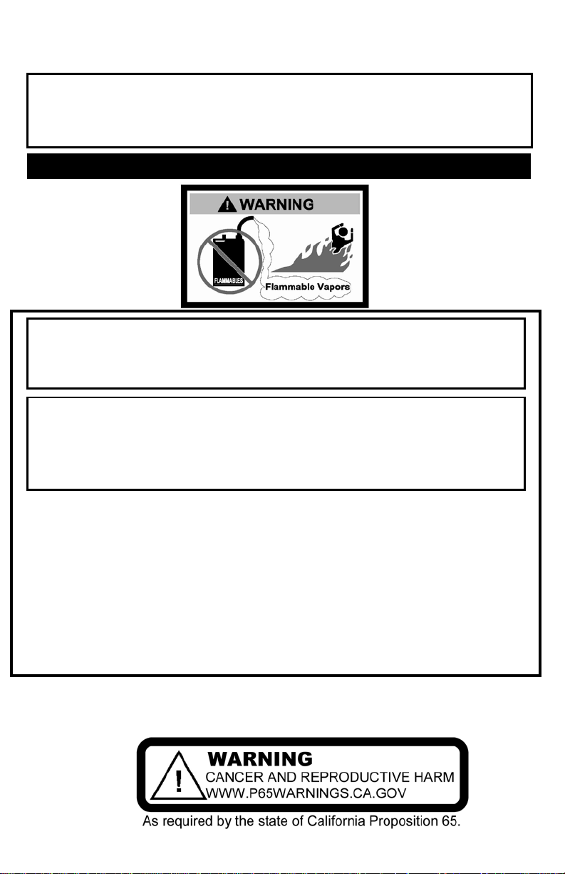
WARNING: If the information in these instructions is not
followed exactly, a fir e or expl osi on m ay result causi ng
property damage, personal injury or death.
FOR YOUR SAFETY
Do not store or use gasoline or other flam m abl e, combustible,
or corrosive vapors and liquids in the vicinity of this or any
other appliance.
WHAT TO DO IF YOU SMELL GAS
• Do not try to light any appliance.
• Do not touch any electrical switch; do not use any phone in
your building.
• Immediately call your gas supplier from a neighbor’s phone.
Follow the gas supplier ’s instructions.
• If you cannot reach your gas supplier, call the fire department.
Installation and service must be prefor m ed by a qualifi ed
For your family’s comfort, safety and convenience we recommend
this water heater be install ed and ser viced by a plumbing
professional.
238-51006-00D REV 5/18

2
CONGRATULATIONS!
You have just purchased one of the finest water heaters on the market
today!
This installation, operation and i nst r uct ion manual will
explain in detail the instal lation and maintenance of your
new Power Direct Vent Gas Water Heater. W e st r ongly
recommend that you contact a plumbing professional f or
the installation of thi s water heater.
We require that you carefully read this manual, as well as
the enclosed warranty, and refer t o i t when questions arise.
If you have any specific questions concerning your
warranty, please consult the plumbing professional from
whom your water heater was purchased. For your records
we recommend that you wr ite the model, serial number and
installation date of your w at er heat er i n t he m ai ntenance
section in the back of this manual.
This manual should be kept with the water heat er .
Special Flammable Vapor Ignition Resistant System:
This water heater is equipped with a Flammable Vapor Ignition Resistant System. In
the event of improper usage or storage of gasoline or other flammable materials in
the location where the water heater is installed, the technology will resist ignition of
the flammable vapors outside the confines of the water heater.
The Flammable Vapor Ignition Resistant System features:
• Flammable Vapor Sensor.
• Automatic Ignition Device.
• Sight Window to observe operation of pi lot and burner.
FOR YOUR SAFETY: Activation of the Flammable Vapor Ignition Resistant System
occurs when flammable vapors are present in the room where the water heater is
installed. If flammable vapors are detected and/or sensed:
• Do not try to light any appliance.
• Do not touch any electrical switch; Do not use any phone in your building.
• Leave the premises and immediately call the fire department from a
Once the flammable vapor has been evacuated, contact your plumbing professional
or the manufacturer for further instructions. Replacement of a Flammable Vapor
Ignition Resistant System equipped water heater due to a flammable vapor
shutdown is not covered under the terms of the limited warranty.
neighbor’s phone. Follow the fire department’s instructions.

3
TABLE OF CONTENTS
page
GENERAL INFORMATION ................................................................. 4
INSTALLATION. .................................................................................. 5
Locating The Water Heater ......................................................... 5
Minimum Clearances ................................................................... 8
Venting .......................................................................................... 8
Specifications for
48 Gal. (181.6 L) ...................................................................... 12
Specifications for
40 Gal. (151.4 L)
50 Gal. (189.2 L) ...................................................................... 24
Vent pipe preparation and joining .................................................... 35
Water Connections ...................................................................... 36
Gas Connections .......................................................................... 39
Electrical Connections ................................................................ 40
Wiring Diagram ...................................................................... 41
GENERAL OPERATION ..................................................................... 42
Lighting and Shutdown Instructions ......................................... 43
Thermostat Adjustment ............................................................... 44
Burner Flame Check .................................................................... 45
MAINTENANCE ................................................................................... 46
TROUBLESHOOTING ......................................................................... 50
PARTS LIST AND PARTS LIST DRAWING ....................................... 53
INSTALLATION INSTRUCTIO NS FOR POTABLE WATER AND
SPACE HEA TING ................................................................................ 54
NOTES ................................................................................................. 55
4
GENERAL INFORMATION
CAUTION
Incorrect operation of this appliance may create a hazard to life
and property and will nullify the warranty.
WARNING
Prior to connecting the gas supply line to a gas fired water heater,
appliances.
DANGER
Do not store or use gasolin e or other flammable, combustible, or
appliance.
This gas-fired water heater’s design is certified by CSA International under the
American National Standard Z21.10.1 and CSA 4.1-M, most current editions at
the time of manufacture. This is a category III water heater.
This water heater must be installed in accordance with local codes or, in the
absence of local codes, the National Fuel Gas Code, ANSI Z223.1-Latest
Edition) and/or in Canada CAN/CGA B149 Installation Codes (Latest Editions).
The warranty for this water heater is in effect only when the water heater is
installed, adjusted, and operated in accordance with these Installation and
Operating Instructions. The manufacturer will not be held liable for any damage
resulting from alteration and/or failure to comply with these instructions.
This water heater is not design certified for installation in a mobile home. Such
an installation may create a hazardous condition and will nullify the warranty.
ensure that the gas supply line does not have moisture/water or
dirt/scale inside the gas line. Commonly this check is done at the
lowest point in the gas distribution system prior to gas burning
Do not use this appliance if any external part to the tank has been submerged in
water. You should contact a qualified service technician to inspect the appliance
and to replace any part of the control system including the combination gas
control which has been submerged in water. See the Gas Connections section
of this manual before servicing or replacing a water heater that has had any
external part to the tank submerged in water.
corrosive vapors and liquids in the vicinity of this or any other
IMPORTANT
Before proceeding, please inspect the water heater and its components for
possible damage. DO NOT install any water heater with damaged
components. If damage is evident then please contact the supplier where the
water heater was purchased or the manufacturer listed on the rating plate for
replacement parts.
5
General Information continued-
WARNING
Water heaters are heat producing appliances. To avoid damage or
OR VENT-AIR INTAKE SYSTEM.
Make sure that you check the rating plate and combination gas control on the
water heater to be certain that the type of gas being supplied corresponds with
the marking on the rating plate and combination gas control.
A sacrificial anode(s) is used to ex tend tank life. Removal of any anode, except
for inspection and/or replacem ent, will nullify the warranty. In areas where water
is unusually active, an odor may occur at the hot water faucet due to a reaction
between the sacrificial anode and impurities in the water. If this should happen,
an alternative anode(s) may be purchased from the supplier that installed this
water heater. This will m inimize the odor while protecting the tank. Additionally,
the water heater should be flushed with appropriate dissolvers to eliminate any
bacteria.
INSTALLATION
Locating The Water Heater
injury, do not store materials against the water heater or vent-air intake
system. Use proper care to avoid unnecessary contact (especially by
children) with the water heater and vent-air intake components.
NO CIRCUMSTANCES MUST FLAMMABLE MATERIALS, SUCH AS
GASOLINE OR PAINT THINNER BE USED OR STORED IN THE VICINITY
OF THIS WATER HEATER, VENT-AIR INTAKE SYSTEM OR IN ANY
LOCATION FROM WHICH FUMES COULD REACH THE WATER HEATER
UNDER
DO NOT install the water heater in a n y location where gasoline or
flammable vapors are likely to be present.
Water heaters in residential garages must be installed and located, or
protected, to avoid physi cal damage. For other installations refer to local
codes. In the absence of local codes, the water heater must be installed in
compliance with the National Fuel Gas Code, (ANSI Z223.1- Latest
Edition), or in Canada CAN/CGA B149.1 Natural Gas Installation Code
(Latest Edition) or CAN/CGA B149 .2 Propane Installation Code (L atest
Edition).
The location of this water heater is of the utmost importance. Before installing
this water heater, read the installation section of these instructions. After
reading these installation and operating instructions, select a location for the
water heater where the floor is level and is easily accessible to gas and water
supply lines. DO NOT locate the water heater where water lines could be
subjected to freezing temperatures. Make sure the cold water pipes are
not located directly above the gas control so that condensate during
humid weather does not drip on the controls.

6
Installation (Locating The Water Heater) continued-
WARNING
Liquefied petroleum gases/propane gas are heavier th an air and
Water heater corrosion and component failure can be caused by the heating
and breakdown of airborne chemical vapors. Examples of some typical
compounds that are potentially corrosive are: spray can propellants, cleaning
solvents, refrigerator and air conditioning refrigerants, swimming pool
chemicals, calcium and sodium chloride, waxes and process chemicals. These
materials are corrosive at very low concentration levels with little or no odor to
reveal their presence. NOTE: DAMAGE TO THE WATER HEATER CAUSED
BY EXPOSURE TO CORROSIVE VAPORS IS NOT COVERED BY THE
WARRANTY. DO NOT OPERATE THE WATER HEATER IF EXPOSURE HAS
OR WILL OCCUR. DO NOT STORE ANY POTENTIALLY CORROSIVE
COMPOUNDS IN THE VICINITY OF THE WATER HEATER.
To comply with NSF requirements this water heater is to be:
a) Sealed to the floor with
sealant, in a smooth
and easily cleanable
way, or
b) Installed with an
optional leg kit that
includes legs and/or
extensions that provide
a minimum clearance
of 6” beneath the water
heater.
will remain at floor level if there is a leak. Basements, crawl spaces,
closets, and areas below ground level will serve as pockets for
accumulation of leaking gas. Before lighting, smell a ll around the
appliance area for gas. Be sure to smell next to the floor.
IF YOU SMELL GAS:
• Do not try to light any appliance.
• Do not touch any electric switch; do not use any telephone in
your building.
• Immediately call your gas su p plier from a neighbor’s
telephone. Follow the gas supplier’s instructions.
• If you cannot reach your gas supplier, call the fire department.
DO NOT OPERATE APPLIANCE UNTIL THE LEAKAGE IS
CORRECTED!
7
Installation (Locating The Water Heater) continued-
WARNING
DO NOT ATTEMPT TO LIGHT ANY GAS APPLIANCE IF YOU ARE
NOT CERTAIN OF THE FOLLOWING:
• Liquefied petroleum gases/propane gas and natural gas have
an odorant added by the gas supplier that aids in the detec tion
of the gas.
• Most people recogni ze this odor as a “sulfur” or “rotten egg”
smell.
• Other condition s, such as “odorant fade” can cause the
odorant to diminish in intensity, or “fade”, and not be as
readily detectable.
• If you have a diminished sense of smell, or are in any way
unsure of the presence of gas, immediately contact your gas
supplier from a neighbor’s telephone.
Gas detectors are available. Contact your gas supplier, or
plumbing professional, for more information.
The water heater must be located close enough to the outside wall to keep the
venting distance within the maximum distance described in the installation
instructions. Locate the water heater as close as possible to the vent opening.
Read the venting section in this installation instruction manual before locating
the water heater.
This water heater must be located in an area where leakage of the tank or water
line connections and the combination temperature and pressure relief valve will
not result in damage to the area adjacent to the water heater or to lower floors
of the structure. When such locations cannot be avoided, a suitable drain pan
adequately piped for proper drainage must be installed under the water heater.
The drain pan, as described above, can be purchased from your plumbing
professional. The drain pan must be piped to an adequate drain. The piping
must be at least 3/4 inch (1.9 cm) in diameter and pitched for proper drainage.
It is recommended that a minimum clearance of four (4) inches (10.2 cm) be
provided on the side of the water heater for servicing and maintenance of the
combination temperature and pressure relief valve.
This water heater MUST be installed indoors out of the wind and weather.
Note: For California ins tallation this water heater must be braced,
anchored, or strapped to avoid falling or moving during an earthquak e.
See instructions for correct installation procedures. Instructions may be
obtained from DSA Headquarters Office, 1102 Q Street, Suite 5100,
Sacramento, CA 95811.
8
WARNING
Failure to adhere to these installation and operating instructions
Minimum Clearances
may create a ha zard to life and property and will nullify the
warranty.
This installation must allow access to the front of the water heater and adequate
clearance must be provided for servicing and operating this water heater. The
water heater may be installed on either a combustible or non-combustible floor.
If the water heater is to be installed directly on carpeting, it must be installed on
top of a metal or wood panel extending beyond the full width and depth of the
appliance by at least three (3) inches (7.6 cm) in any direction or, if the
appliance is to be installed in an alcove or closet, the entire floor must be
covered by the panel. The minimum clearances to combustibles for this water
heater are: zero (0) inch (0 cm) from the sides and rear, five (5) inches (12.7
cm) from the front of the jacket, zero (0) inch (0 cm) from the vent connector
and fifteen (15) inches (38.1 cm) from the jacket top. Increase distances to
provide clearance for servicing.
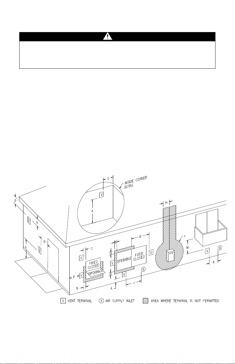
Venting
Figure 1 – Direct Vent Terminal Clearances

9
Venting continued-
12 inches
(30 cm)
12 inches
(30 cm)
12 inches
(30 cm)
12 inches
(30 cm)
Vertical clearance to ventilated soffit located above the terminal within a
horizontal distance of 2 feet (61 cm) from the center line of the terminal
3 feet (91 cm)
assembly
36 inches
(91 cm)
Clearance to non-mechanical air supply inlet to building or the
combustion air inlet to any other appliance
12 inches
(30 cm)
12 inches
(30 cm)
3 feet
horizontally
Clearance above paved sidewalk or paved driveway located on public
property
7 feet
(2.13 m)†
7 feet
(2.13 m)†
12 inches
(30 cm) ‡
12 inches
(30 cm) ‡
A= Clearance above grade, veranda, porch, deck or balcony
B= Clearance to window or door that may be opened
C= Clearance to permanently closed window *b *b
D=
E= Clearance to unventilated soffit *b *b
F= Clearance to outside corner *b *b
G= Clearance to inside corner *b *b
Canadian
1
Installations
*b *b
Installations2
US
Clearance to each side of center line extended above meter/regulator
H=
assembly
I= Clearance to service regulator vent outlet or oil tank vent
J=
K= Clearance to a mechanical air supply inlet
L=
M= Clearance under a veranda, porch, deck, or balcony
1
In accordance with the current CAN/CGA-B149 Installation Codes.
2
In accordance with the current ANSI Z223.1-(Latest edition)/NFPA 54 National Fuel Gas Code.
within a height 15
feet (4.6 m) above
the
meter/regulator
6 feet
(1.83 m)
*b
*b
(91 cm)
above if
within 10
feet
† A vent shall not terminate directly above a sidewalk or paved driveway that is located between two singlefamily dwellings and serves both dwellings.
‡ Permitted only if a veranda, porch, deck or balcony is fully open on a minimum of two sides beneath the
floor.
*a) A minim um clearance value determined by testing in accordance with section 5.21.1 of ANSI Z21.10.1,
latest edition.
*b) “Clearance in accordance with local installation codes and the requirements of the gas supplier”.
The vent system must terminate so that proper clearances are maintained as cited
in local codes or the latest edition of the National Fuel Gas Code, ANSI
Z223.1.73.4e and 7.8a, b as follows:
1. Do not terminate near soffit vents or crawl space or other area where condensate
or vapor could create a nuisance or hazard or cause property damage.
2. Do not terminate the exhaust vent terminal where condensate or vapor could cause
damage or could be detrimental to the operation of regulators, relief valves, or
other equipment.
3. Do not terminate the exhaust vent terminal over public area or walkways where
condensate or vapor can cause nuisance or hazard.
4. The vent shall terminate a minimum of 12” (25.4 cm) above expected snowfall level
to prevent blockage of vent termination.
10
Venting continued-
Clearance to com bus t ibles for all vent ing pipes
and terminals
For installations in Canada
for clearances to combustibles
WARNING
Risk of carbon monoxide poisoning or fire due to joint separa tion
or pipe breakage.
This water heater must be properly vented and connected to an
dependent upon full compliance with these installation instructions.
Venting system must not pass through rated fire separations.
The venting system must be free to expand and contract. This venting
system must be supported in accordance with these instructions.
NOTICE
In locations where sustained outside air temperatures are below freezing, it
is possible for the vent terminations to accumulate ice build-up due to
adverse local climate conditions (prevailing wind direction, wind speed,
termination orientation, etc.). The optional concentric vent terminal is more
resistant to this ice build-up. In more severe temperature conditions, an
optional manufacturer approved air intake relief device is available and may
be installed, per the instructions, to prevent nuisance shut down of the
water heater. The air intake relief device may be installed with the
concentric vent termination or the standard separate vent terminations.
Consult the concentric vent and/or the air intake relief device instructions for
installation requirements.
Vent pipes serving power vented appliances are classified by building codes as
“vent connectors”. Required clearances from combustible materials must be
provided in accordance with information in this manual under LOCATION OF
WATER HEATER and CLEARANCES, and with National Fuel Gas Code and
local codes.
For installations in the US
0” minimum
DO NOT place of insulation or other materials in the required clearance spaces
between the venting to combustible material unless otherwise specified.
Refer to vent pipe and terminal
manufacturer’s installation instructions
approved vent system in good condition. DO NOT operate water heater
with the absence of an approved vent system. A clean and unobstructed
vent system is necessary to allow noxious fumes that could cause injury
or loss of life to vent safely and will contribute toward maintaining the
water heater’s efficiency. The acceptance of the venting system is
11
Venting continued-
For installations in the U S only
D2661)
For installations in CANADA
For installations in the US only
(ASTM D-2235)
For installations in CANADA
NOTICE
Use of cellular c ore PVC (ASTM F891), cellular core CPVC, or Radel
®
, and
covering non-metallic venting with thermal insulation is prohibited.
NOTICE
For installations in Canada, field supplied vent piping must comply with
CAN/CGA B149.1 (latest edition) and be certified to the Standard For Type
BH, Class II, 65°C, Gas Venting Systems, ULC S636. Components of this
listed system shall not be interchanged with other vent systems or unlisted
pipe/fittings. All components and specified primers and cements of the
certified vent system must be from a single system manufacturer and not
intermixed with other system manufacturer’s vent system parts. The supplied
vent connector and vent termination are certified under ULC S636 and are
also certified as part of the water heater. Refer to the following tables for
approved venting materials, primers, and cements. All approved primers and
cements are to be used within their marked time limitations.
Approved Venting Materials
• PVC DWV (ASTM D-2665)
• PVC Sch. 40, 80, 120 (ASTM-
D1785)
• CPVC Sch. 40, 80 (ASTM-
F441)
• CPVC (ASTM D2846)
• ABS Sch. 40 DWV (ASTM
Approved Primers and Cements
• PVC and CPVC Primer
(ASTM-F656)
• PVC Cement (ASTM D-2564)
• CPVC Cement (ASTM F493)
• ABS Primer and Cement
• ULC S636 approved PVC for
flue gas venting rated Class II,
65°C
• ULC S636 approved CPVC for
flue gas venting rated Class II,
65°C
• ULC S636 approved Primer and
Cement for flue gas venting
rated Class II, 65°C
(polyphenosulfone) in non-metallic venting systems is prohibited

12
Venting System Condensation
Condensate formation does not occur in all installations of power direct vented
water heaters, but should be protected against on installations where
condensation can form in the venting system.
Formation of condensation in the venting system of Power Vented water
heaters is dependent upon installation conditions including, but not limited to:
ambient temperature and humidity of installation location;
ambient temperature and humidity of venting space;
vent distance and slope;
and product usage.
In order to effectively control condensate from adversely affecting the
mechanical components of the water heater several methods may be
employed:
1. For horizontal installations the vent pipe can be installed with a
downward slope (not less than 1/8" (3 mm)) and away from the blower.
2. In order to prevent condensate from draining back into the blower
(vertical or horizontal runs), an optional condensate kit is available as a
service part (Condensate kit, p/n 239-45875-00). A factory supplied
exhaust adapter with drain outlet mounts directly to the blower outlet
and is secured with two hose clamps, one to the blower and the other to
the vent pipe. Tubing is provided to drain any accumulated condensate
away from the water heater and to a suitable drain. The kit comes
PART I - Venting Specifications for:
48 Gallon (181.6L)
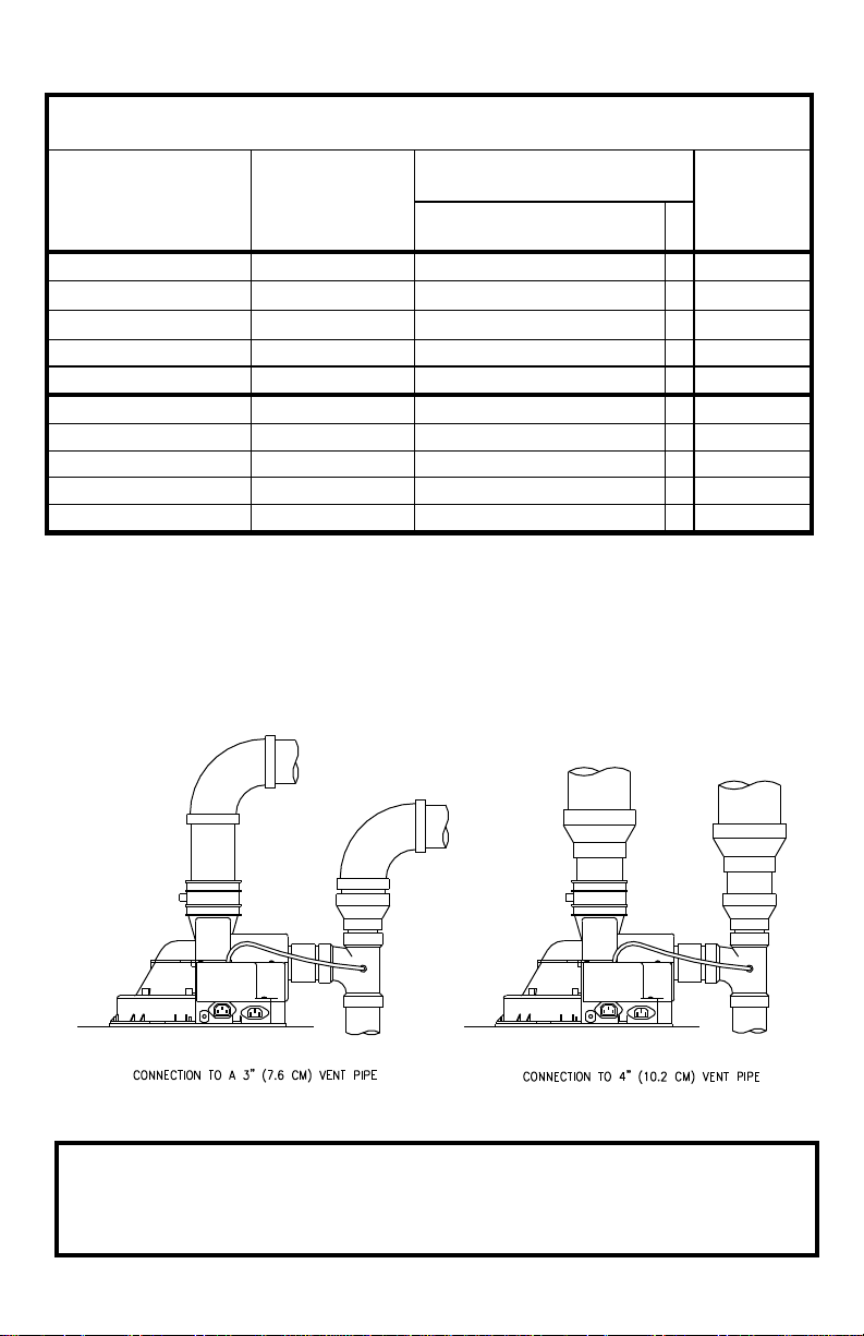
This water heater is a power vented appliance and is designed to intake and
exhaust the products of combustion through 3” (7.6 cm) or 4” (10.2 cm)
diameter vent pipe to the outdoors. This water heater may be either vented
horizontally through the wall or vertically through the roof. Use a 3” (7.6 cm) to
4” (10.2 cm) reducer to connect to the intake and outlet when using 4” (10.2 cm)
vent pipe. Apply the proper cement at the joint locations. Table 1 lists the
maximum vent lengths for this water heater using 3” (7.6 cm) intake and
exhaust pipe. If possible, locate the water heater so that the venting length and
number of elbows are kept to the minimum distance necessary to reach the
outside. If the installation requires venting lengths that exceed the lengths listed
for 3” (7.6 cm) vent pipe in Table 1, then use 4” (10.2 cm) vent pipe for the vent
connector.
complete with instructions for proper installation.
13
Venting continued-
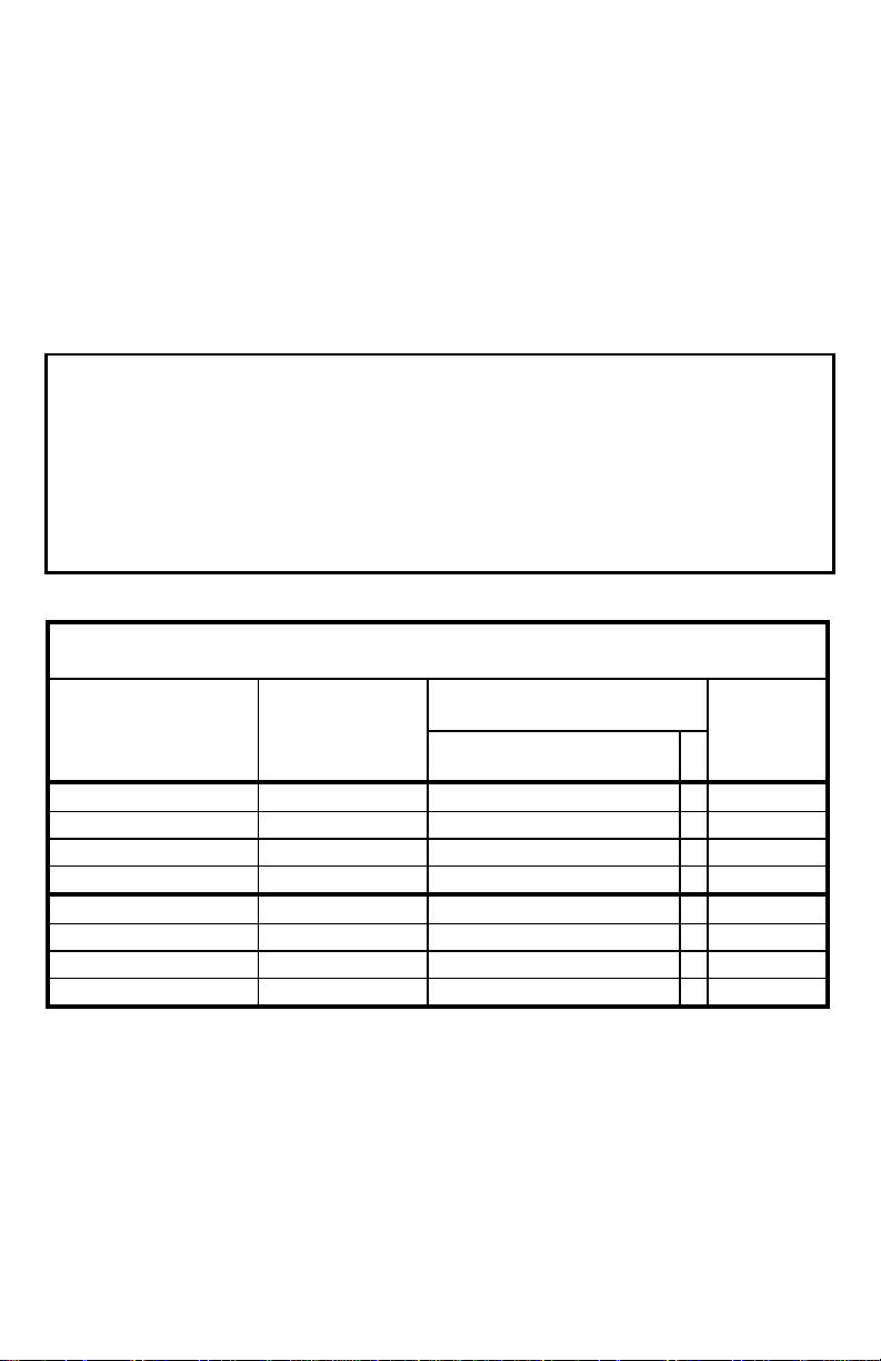
TABLE 1 - VENT CONNECTOR LENGTHS
FOR 3” (7.6 cm) DIAMETER VENT PIPE
Maximum straight
Length ft (m)
Minimum
ft (m)
48 gal.
Through the Wall
1
55 (16.8)
2 (.6)
Through the Wall
2
50 (15.2)
2 (.6)
Through the Wall
3
45 (13.7)
2 (.6)
Through the Wall
4
40 (12.2)
2 (.6)
Through the Roof
0
60 (18.3)
7 (2.1)
Through the Roof
1
55 (16.8)
7 (2.1)
Through the Roof
2
50 (15.2)
7 (2.1)
Through the Roof
3
45 (13.7)
7 (2.1)
Table 2 lists the venting distances allowed with 4” (10.2 cm) diameter vent pipe.
When venting with 4” (10.2 cm) vent pipe, use a 4” (10.2 cm) to 3” (7.6 cm)
reducer to exit through the building wall with 3” (7.6 cm) vent pipe. Use the 3”
(7.6 cm) vent terminal supplied with the water heater to terminate on the outside
of the building. If the length of 3” (7.6 cm) vent pipe needed to go through the
wall is greater than 14” (35.5 cm), use 4” (10.2 cm) to go through the wall and
reduce to 3” (7.6 cm) vent pipe immediately after exiting the outside wall. Refer
to the venting illustrations on the following pages. Make sure the vent pipe
terminal elbow fitting is at least 1” (2.5 cm) away from the edge of the wall.
IMPORTANT
The minimum equivalent length for the exhaust portion of the vent is 7
feet. The maximum equivalent vent length for the exhaust is 60 feet for
3” diameter pipe and 100 feet for 4” diameter pipe. The intake portion of
the vent must be equal to or less than the vent length of the exhaust.
The tables below are provided for your quick reference, some
installations may require a greater number of elbows. When calculating
equivalent vent length, one 90º elbow is equivalent to 5 feet.
# of Elbows
Terminating
(excl. vent
term.)
straight
Length
14
Venting continued-
TABLE 2 -VENT CONNECTOR LENGTHS
FOR 4” (10.2 cm) DIAMETER VENT PIPE
Maximum straight
Length ft (m)
Min
ft (m)
48 gal.
Through the Wall
1
95 (29.0)
10 (3.1)
Through the Wall
2
90 (27.4)
10 (3.1)
Through the Wall
3
85 (25.9)
10 (3.1)
Through the Wall
4
80 (24.4)
10 (3.1)
Through the Wall
5
75 (22.9)
10 (3.1)
Through the Roof
0
100 (30.5)
15 (4.6)
Through the Roof
1
95 (29.0)
15 (4.6)
Through the Roof
2
90 (27.4)
15 (4.6)
Through the Roof
3
85 (25.9)
15 (4.6)
Through the Roof
4
80 (24.4)
15 (4.6)
Terminating
# of 90°
Elbows (excl.
vent term.)
straight
Length
NOTE: When using 4” (10.2 cm) vent pipe, use two 4” (10.1 cm) to 3” (7.6
cm) reducers for each po rtion of the vent. One reducer is installed just
after the blower and the other reducer is used just prior to exiting the
building. Exit the building wall with 3” (7.6 cm) vent pipe using the 3”
(7.6 cm) 90° vent terminal supplied. Two 45° elbows are equivalent to one
° elbow.
90
Figure 2
IMPORTANT
All of the Venting connections must be leak checked with a soap and
water solution upon initial start up of the water heater. Any leaks must
be repaired before continuing operation of the water heater.
15
Venting continued-
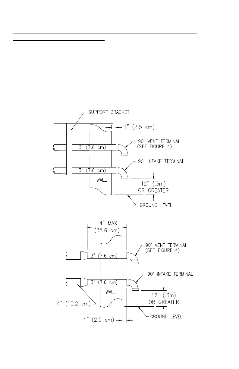
THROUGH THE WALL VENTING: (HORIZONTAL VENTING WITH
STANDARD VENT TERMINALS).
Cut two 3 1/2 in. (8.9 cm) diameter holes in the wall at the point where the vent
connector is going to pass through the wall. Use the proper cement to secure
the 90° vent terminal provided with the water heater to the vent connector. The
distance between the edge of the 90° vent terminal and the exterior wall (see
Figure 3) must be 1 in. (2.5 cm). The exhaust and intake must not be less than
16 in. (40.6 cm) apart (see figure 4a) and the exhaust terminal must be a
minimum of 3 in. (7.6cm) higher than the intake terminal. Use the proper
cement and assembly procedures to secure the vent connector joints between
the terminal and the blower outlet. Provide support brackets for every 5 feet
(1.5m) of horizontal vent.
3” VENT INSTALLATION
4” VENT INSTALLATION
Figure 3
16
Venting continued-
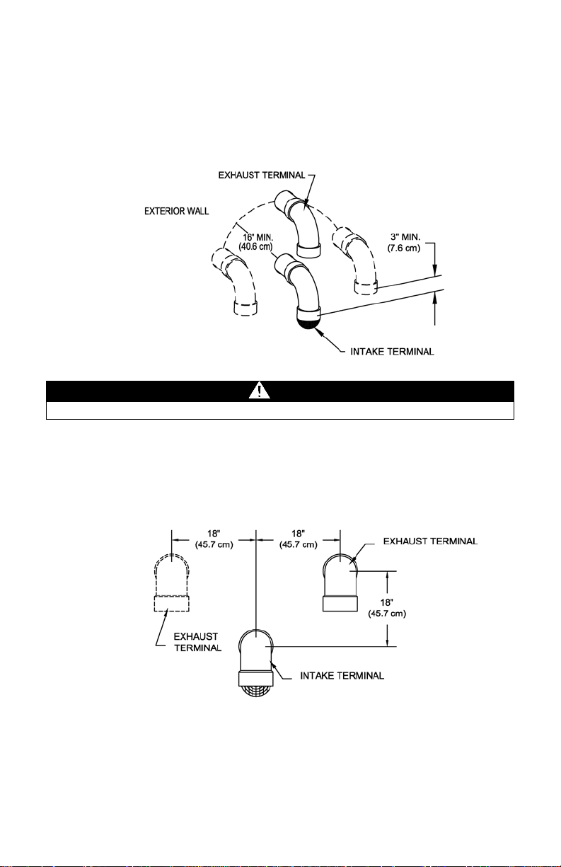
CAUTION
NEVER INSTALL AIR INTAKE ABOVE EXHAUST
Vent terminal configurations for through the wall venting.
When venting through the wall, the exhaust terminal must exit the structure at a
minimum distance of 16” (40.6 cm) from the intake terminal. The exhaust terminal must
exit the structure at a minimum of 3 in. (7.6 mm) higher than the intake terminal. The
exhaust terminal must not be located below the intake terminal for any reason (see
figure 4a below for examples of acceptable vent terminal configurations).
Figure 4a
When local conditions present a risk of ice accumulation on the vent terminals, the
configurations in 4b and 4c or the concentric termination are preferred.
The air intake screen can be removed for cold installations but this may make the air
intake susceptible to debris buildup from birds or other animals. If the air intake
screen is removed to prevent freezing, it is recommended that the air inlet screen be
installed during the spring.
Figure 4b
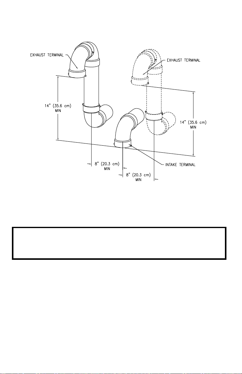
17
Venting continued-
Figure 4c
IMPORTANT
When using the vent terminal configuration shown in 4c the extra
elbows must be accounted for in the total vent length see Table 3 or
Table 4.
 Loading...