

Page 1
SUPPLEMENT TO INSTRUCTION MANUAL
P/N 238-47936-00
Burner Flame Check
(Replaces pg. 46 in instruction manual.)
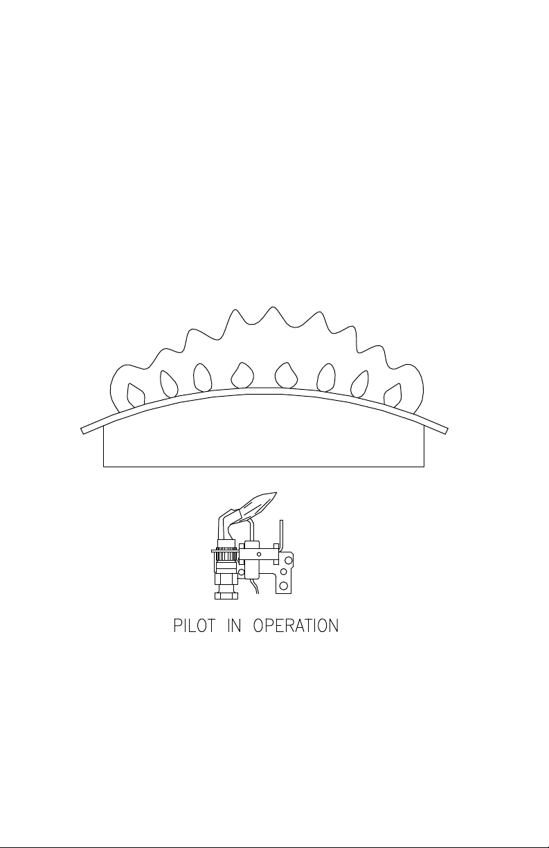
Steel Burner: These models are equipped with self-adjusting air mixture and
do not have an adjustable air shutter (See Figure 18). At periodic intervals a
visual check of the main burner and pilot flames should be made to determine if
they are burning properly. The main burner flame should light smoothly from
the pilot.
Figure 18
238-48838-00C REV 11/12
Page 2
(Replaces pg. 54 in instruction manual.)
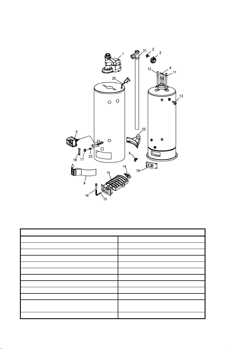
PARTS LIST DRAWING
Note: Provide the part name, model and serial numbers of the water heater
when ordering parts.
PARTS LIST
PART NAME AND DESCRIPTION
1. Blower Assembly 13. T&P Relief Valve
2. Temp. Switch 14. Pilot Assembly
3. Pressure Switch N.O. 15. Main Burner Orifice
4. Flue Baffle 16. Gas Feedline
5. Honeywell Gas Control Valve 17. Flammable Vapors Sensor
6. Drain Valve 18. Sensor Harness
7. Fiberglass Insulation (not shown) 19. Inner Door Assembly
8. Foam Insulation (not shown) 20. Blower Harness
9. Outer Door 21. Tee and Vent Pipe Assembly
10. Steel Burner 22. Air Intake Boot
11. Diptube–Nipple 23. Vapor Switch Mounting
Bracket
12. Anode–Nipple
2
Page 3

(Replaces pg. 55 in instruction manual.)
PARTS LIST DRAWING
1. All piping components connected to this water heater for space heating
applications must be suitable for use with potable water. In
Massachusetts, space heating piping length must not exceed 50 feet.
2. Toxic chemicals, such as those used for boiler treatment, must not be
introduced into potable water used for space heating.
3. This water heater must not be connected to an existing heating
system or component(s) previously used with non-potable water
heating appliance.
4. When the system requires water for space heating at temperatures
higher than required for other means, such as an ASSE approved
mixing valve must be installed to temper the water for those uses in
order to reduce the scald hazard potential.
Please refer to the illustration below for suggested piping arrangement.
3
Page 4

NOTES
4
 Loading...