

Page 1
Save this manual for future reference
Manual 238-49640-00A
SERVICE
MANUAL
Troubleshooting Guide
and Instructions for Service
(To be performed ONLY by
qualified service providers)
Models Covered
by This Manual:
ECO-Defender Safety System® Models
UDS140S*FRN
UDS150S*FRN
UDH1504T*FRN
UDH165T*FRN
UDH175S*FRN
UDH50T45FR*N
UDH65T45FR*N
UDH75T50FR*N
(*) Denotes Warranty Years
Ultra Low NOx Direct Vent Water Heaters
UDS / UDH Series
Page 2

The Bradford White
2
Ultra Low NOx Direct Vent Water Heaters
Table of Contents
Page Service Procedure
Introduction 3 - - -
Trouble shooting Chart 4 - - -
Inner Door Gasket Removal, Inspection, Replacement and Installation 6 I
Thermopile Testing and Replacement 9 II
Pilot Assembly Inspection Cleaning and Replacement 10 III
Igniter, Electrode Testing and Replacement 11 IV
Honeywell Gas Control Testing, Disassembly, and Replacement 20 V
Burner Operation Inspection, Adjustment, Cleaning and Replacement 21 VI
Dip Tube and Anode Inspection and Replacement 23 VII
Generic Parts List 25 - - -
2
Page 3

INTRODUCTION
3
The new Bradford White UDS and UDH water heaters are designed to
provide reliable performance with enhanced standard features. Design
features include reliable standing pilot ignition system, enhanced
diagnostics, simplified servicing, certified FVIR technology and Ultra
Low NOx emissions.
The UDS and UDH water heaters use a combustion system where
combustion air is drawn from the outside of the building. The gas control
maintains water temperature and maintains gas flow. If a situation outside
of normal operating parameters exists, the gas control diagnostic LED wll
flash a code to positively identify an operational issue.
This service manual is designed to facilitate problem diagnosis and
enhance service efficiency. To further promote quicker service times the
gas valve can be removed and replaced without draining the water heater.
Please read the service manual completely before attempting service on
this new series of direct vent water heaters.
How the Safety System Works
During normal operation, air for the combustion chamber is drawn into
the water heater through the vent pipe from outside your building. The air
travels into the closed combustion chamber. The air then mixes in a
normal manner with supplied gas and is efficiently combusted, producing
Ultra Low NOx emissions.
In the unlikely event trace amounts of flammable vapors are present in the
area surrounding the water heater, the sealed combustion system prevents
the flammable vapors from reaching the ignition source.
3
Page 4
4
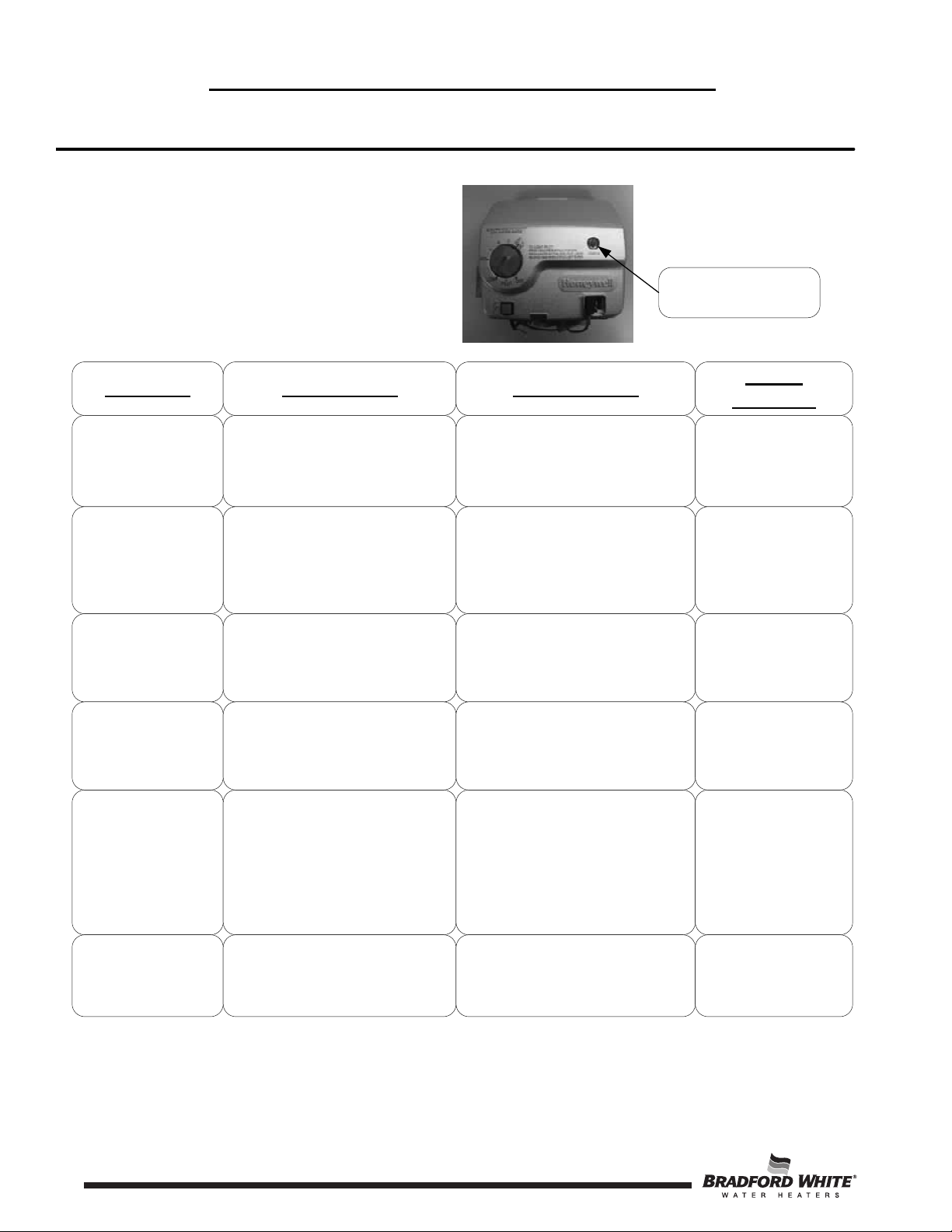
Honeywell Gas Control Troubleshooting Chart
Flammable Vapor Ignition Resistant Water
Heaters
Observe green LED indicator on
Gas Control. Error flash codes are
displayed with a three second pause
before repeating. Check and repair
the system as noted in the
troubleshooting table below.
Green LED Indicator
LED Status Control Status Probable Cause
None (LED not on or
flashing
One flash and three
second pause
Two quick flashes
and a three second
pause
LED on continuously
(Solid)
Two flashes and
three second pause
Pilot assembly is not lit
1. If set point knob is in “PILOT”
position then pilot flame is detected.
Turn set point knob to desired setting.
2. If the set point knob is already at
the desired setting, the water heater is
satisfied.
Gas control is calling for heat (no
fault).
Set point knob has been recently
turned to the “OFF” position. Wait
until LED goes out before
attempting to relight
Weak pilot signal detected. System will
reset when pilot flame is sufficient.
.
Gas Control is not powered. Light pilot.
1. Gas Control is powered and waiting
for the set point knob to be turned to a
water temperature setting.
2. Water heater is satisfied and
operating normally.
Tank temperature below set point of
thermostat.
Set point knob was turned to “OFF”
position.
1. Thermopile failure
2. Unstable pilot
3. Pilot tube block or restricted.
Service
Procedure
If the pilot will not stay
lit replace pilot
assembly. If problem
persists replace Gas
Control.
1. Adjust set point knob
to desired setting.
Normal operation.
LED will go out and the
control will function
normally when the pilot
is lit.
1. See service
procedure II
2. See service
procedure III
3. See service
procedure III
Four flashes and
three second pause
Excessive tank temperature. System
must be reset.
1. Temperature sensor out of
calibration
2. Faulty Gas Control
4
1. See service
procedure V
2. See service
procedure V
Page 5
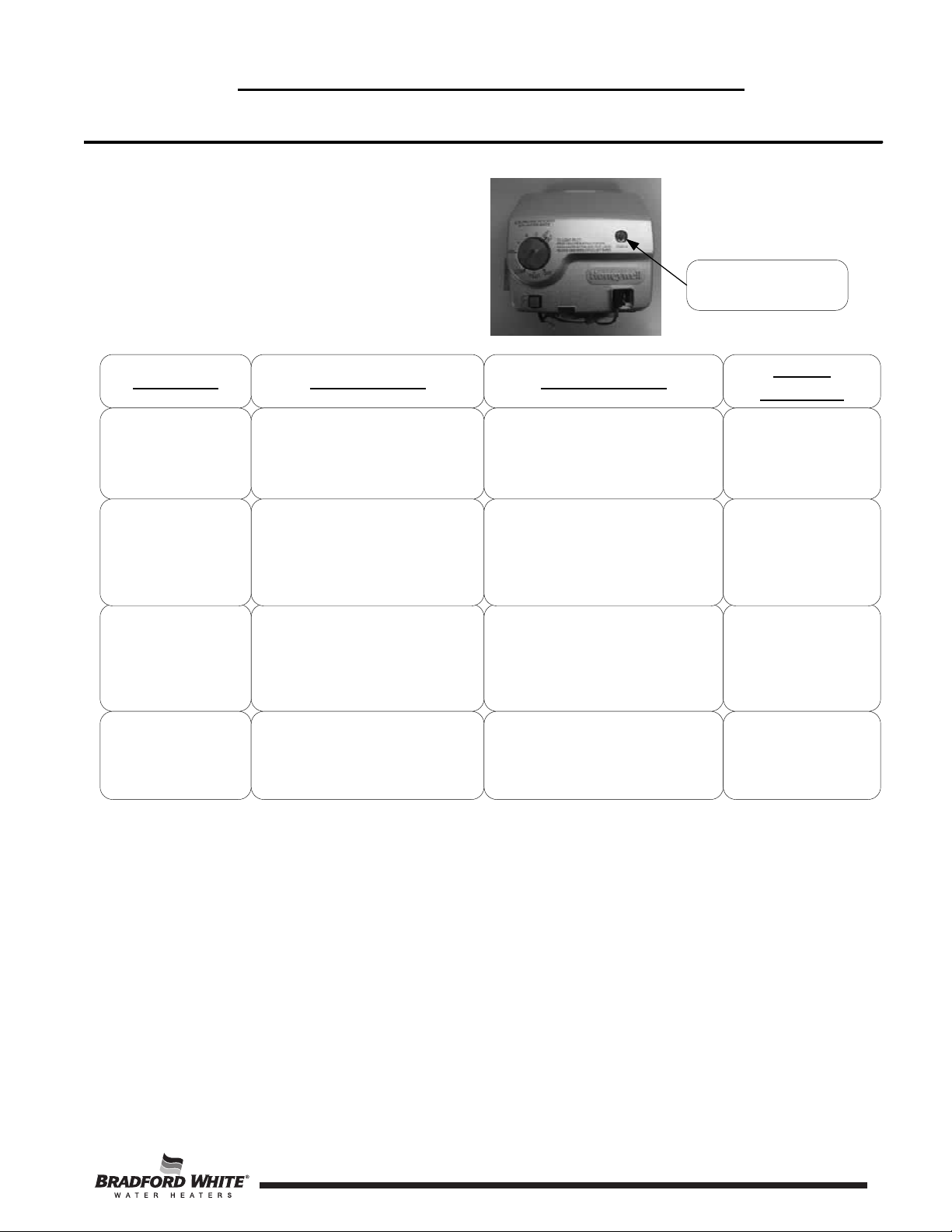
Honeywell Gas Control Troubleshooting Chart
5
Flammable Vapor Ignition Resistant Water
Heaters
Observe green LED indicator on
Gas Control. Error flash codes are
displayed with a three second pause
before repeating. Check and repair
the system as noted in the
troubleshooting table below.
Green LED Indicator
LED Status Control Status Probable Cause
Five flashes and
three second pause
Six flashes and
three second pause
Seven flashes and
three second pause
Eight flashes and
three second pause
Thermostat/well sensor fault.
Water leak detected by accessory
module.
Gas Control electronic fault detected.
Standing pilot remains on while set
point knob is in “OFF” position.
1. Damage to the temperature sensor.
2. Temperature sensor resistance out of
range.
Excessive amount of water in drain
pan/water dam.
1. Control needs to be reset.
2. Control is wet or physically
damaged.
Pilot valve stuck in open position.
Service
Procedure
1. See service
procedure V
1. Check T&P valve
2. Check all water
fittings.
3. Pressurize and leak
test tank.
1. Reset Gas Control
2. Replace Gas
Control.
Replace Gas Control.
5
Page 6
The Bradford White
6
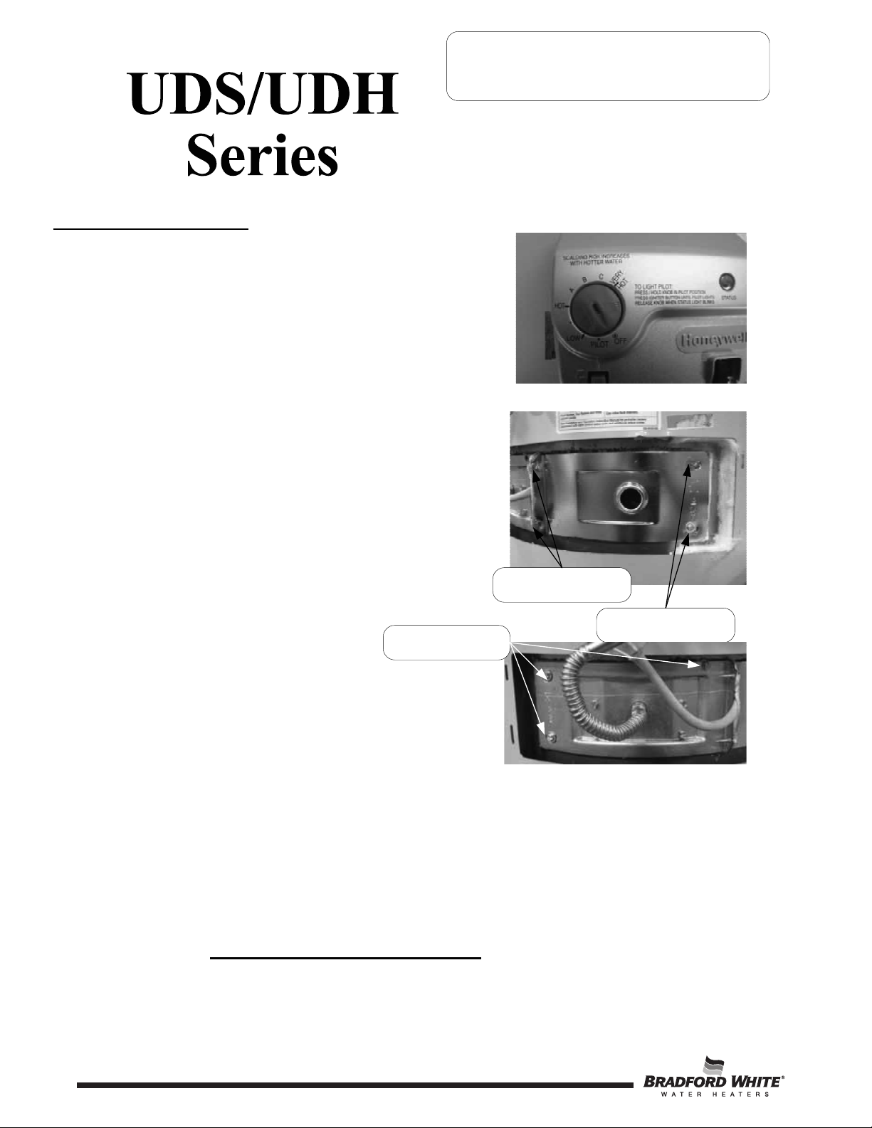
Inner Door Removal Procedure
Step 1. Rotate set point knob of the gas control to the “OFF” position.
Step 2. Turn off the gas supply to the water heater
Step 3. Remove the outer door.
Step 4. Remove the four (4) ¼” hex drive screws holding the
right side inner door in place
SERVICE PROCEDURE I
Inner Door/Gasket Removal, Inspection
Replacement and Reinstallation
Step 5. Remove the three (3) ¼” hex drive screws holding the
left side burner door in place.
¼” Hex Drive Screws at Flange
Area of Inner Door
¼” Hex Drive Screws on Left
Side Inner Door
Step 6. Disconnect the pilot tube from the gas control using a
7/16" wrench. Remove the main burner feedline from
the gas control with a ¾” wrench.
Step 7. Disconnect the spark igniter wire from
the gas control.
Step 8. Remove the burner assembly from the combustion chamber.
tep 9. Fully inspect burner and inner door gaskets for the following:
>Tears >Other imperfections that will inhibit proper seal
>Missing Material >Gasket adhesion to inner door
>Cracks >Material left on combustion chamber (around opening)
>Dirt or debris
If the gasket is not affected by any of the above, gasket replacement is not required. If replacement is
required, proceed to Inner Door Gasket Replacement Procedure.
¼” Hex Drive Screws Right
Side Inner Door
6
Page 7
The Bradford White
7
Inner Door/Gasket Removal, Inspection
SERVICE PROCEDURE I
Replacement and Reinstallation
Inner Door Gasket Replacement
Procedure.
WARNING
If the information in these instructions is not
followed exactly, a fire or explosion may result causing
property damage, personal injury or death.
Step 10. After inspection of inner door as noted in step 9, completely remove gasket and adhesive residue from
burner and left side inner doors as needed.
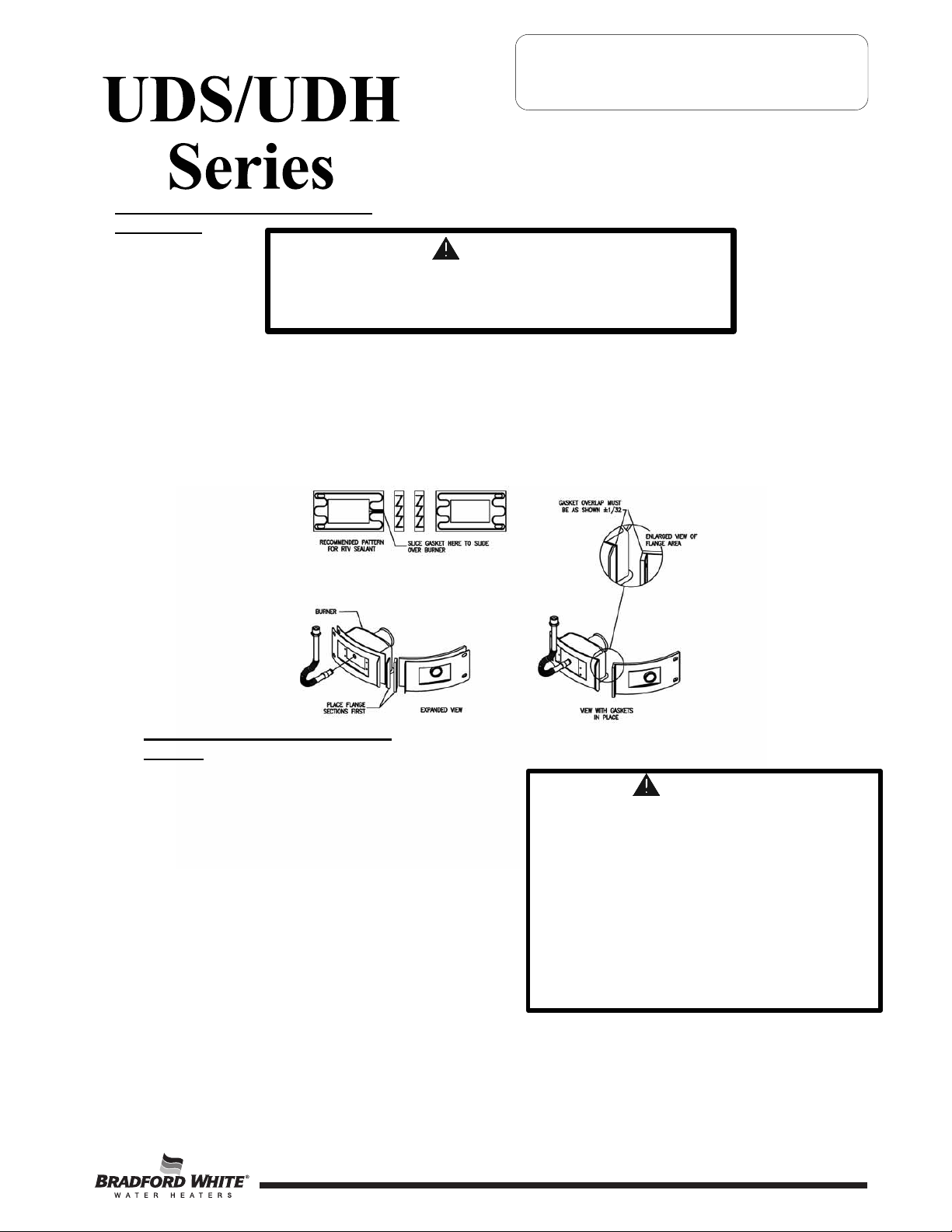
Step 11. Use RTV sealant (recommended bead size 1/8") to secure the inner door gasket to the inner door sections
(right & burner). The burner door gasket must be sliced in the location shown on the illustration below in
order to slide the gasket over the burner venturi. Refer to illustration below for proper RTV sealant
application. Note the overlap configuration in the flange area of the inner door. Set the flange section first, this
will help to achieve the proper over lap position.
Installation of Inner Door With
Gasket.
Step 12. Clean any residual gasket residue or other
debris from combustion chamber surface
before installing the inner door/gasket
assembly.
Step 13. Place the burner door into position first. Tighten
the pilot line nut to the gas control. Tighten the
main burner feedline to the gas control. Use the
¼” hex drive screw without the built-in washer
to secure the right side of the burner door to the
chamber. Use the ¼” hex drive screws with the
built-in washer to secure the left side of the
burner door in place. DO NOT OVER
TIGHTEN SCREWS.
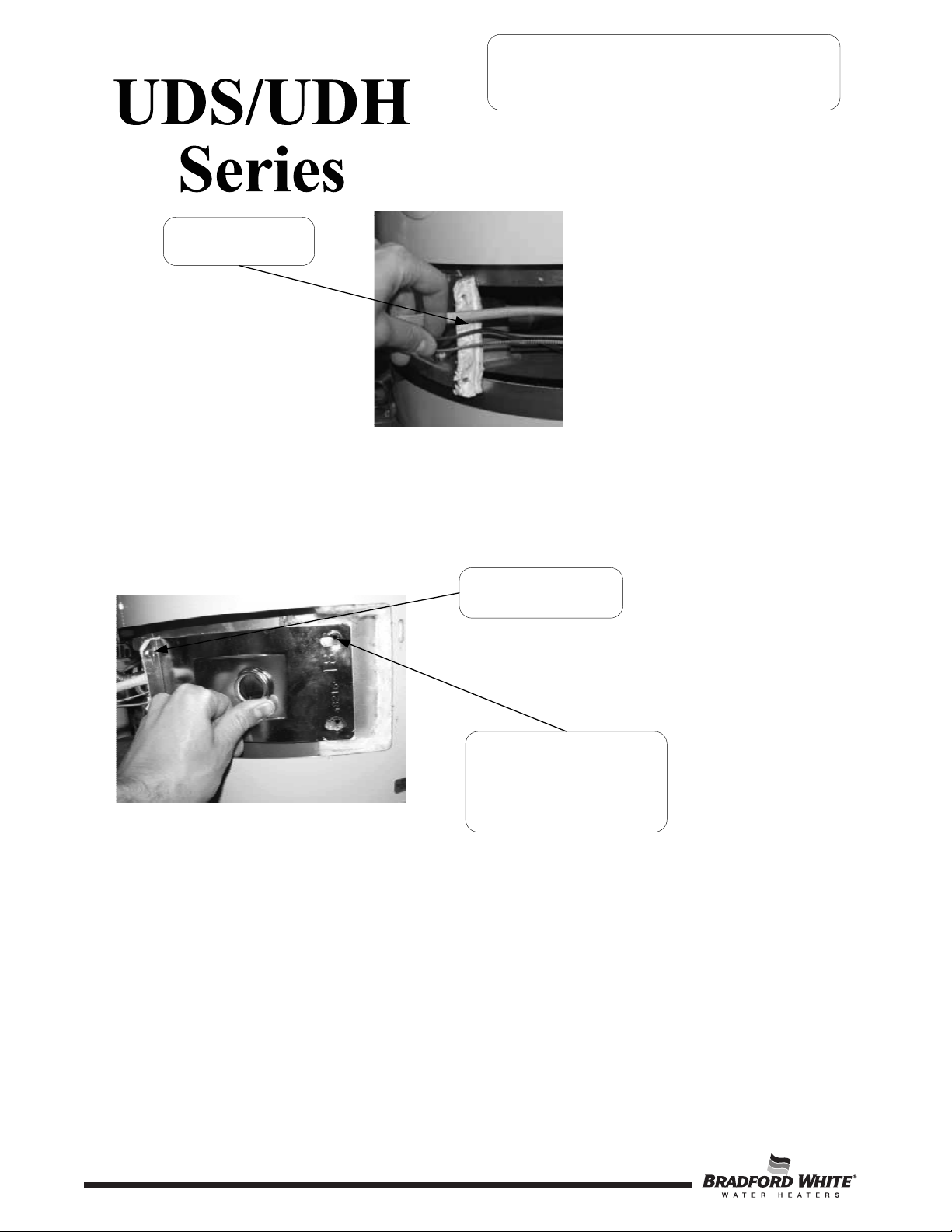
Step 14. Position the fiberglass sock containing the igniter
wire, the pilot tube and the armored thermopile
cable against the inner door flange.
7
WARNING
Stripped fastener connections may allow
for seal breach of inner door. A seal
breach may result in a fire or explosion
causing property damage, personal injury
or death. Do not over tighten screws in
steps 13, 15 and 16.
If a fastener connection is stripped,
contact the manufacturer listed on the
water heater rating plate.
Page 37
Page 8
The Bradford White
8
Inner Door/Gasket Removal, Inspection
SERVICE PROCEDURE I
Replacement and Reinstallation
Position fiberglass sock, pilot
tube and armored thermopile
cable against flange.
Step 15. Firmly place right side inner door flange against the burner door flange and secure with two ¼” drive
screws from step 5. DO NOT OVER TIGHTEN SCREWS.
Step 16. Align right side inner door to combustion chamber and verify the fastener holes of the combustion
chamber are aligned with the right side inner door slotted opening. Verify seal integrity around combustion
opening. Secure right side inner door using 1/4” hex drive screws from step 5. DO NOT OVER TIGHTEN
SCREWS. Verify both burner and right sides of the inner door are properly positioned and sealed against
the combustion chamber.
Secure flange with
¼" drive screws.
Verify threaded hole
alignment with slotted
openings in inner door.
Step 17. Reconnect the igniter wire to the gas control
Step 18. Replace outer jacket burner access door.
Step 19. To resume operation follow the instructions located on the lighting instruction label or the lighting instructions
located in the installation and operation manual.
8
Page 9
The Bradford White
9
SERVICE PROCEDURE II
Thermopile Testing and Replacement
OPEN CIRCUIT THERMOPILE TESTING
The following test should be performed while the pilot flame is on.
Step 1. Turn knob to pilot position and depress.
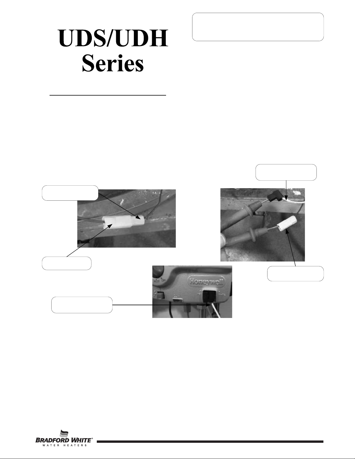
Step 2. Continue pressing knob and remove red (+) thermopile wire from the red wire leading from the gas control.
Also remove white (-) thermopile wire from the gas control.
Step 3. Using a multimeter capable of measuring millivolts, connect the positive side of the multimeter to the
red (+) thermopile wire connector. Connect the negative side of the multimeter to the white thermopile
connector.
White (-) thermopile wire
Red (+) thermopile wire
Red gas control wire
Red (+) thermopile wire
White (-) thermopile wire
Normal thermopile operation will be between 350mV - 850mV. If reading is less than 350mV, replacement of pilot
assembly is recommended following SERVICE PROCEDURE III.
Step 4. If thermopile reading is between 350mV - 850mV, remove multimeter and reconnect red (+) thermopile wire
to red wire leading from the gas control. Reconnect white (-) thermopile wire negative (-) terminal on gas
control.
Step 5. Release Gas Control knob and turn to desired setting to resume normal operation.
9
Page 10

s
The Bradford White
10
PILOT/ELECTRODE ASSEMBLY INSPECTION,
CLEANING AND REPLACEMENT
SERVICE PROCEDURE III
Pilot Assembly Inspection, Cleaning
and Replacement
For Honeywell Control, rotate knob
counter-clockwise to the “OFF”
position.
Step 1. Turn off gas supply to water heater. Rotate knob
of gas control/gas valve
to “OFF” position.
Step 2. Remove outer jacket door.
Step 3. Remove burner and right side inner door per
SERVICE PROCEDURE I, steps 1 through 8.
Step 4 Disconnect thermopile, pilot tube,
and feedline from gas control.
Step 5 Disconnect igniter wire from gas control.
Step 6. Remove pilot/electrode assembly from burner (¼”
drive tool).
Step 7. Inspect pilot for the following:
a) Primary air openings for blockage. Must be free from any
debris (dirt, lint, etc).
b) Kinks or cracks in the pilot tube. If found,
the pilot must be replaced.
Step 8. Inspect pilot orifice:
a) Remove ½" nut from bottom of pilot assembly.
Pilot tube
Igniter wire
Primary air
opening
Thermopile
connections
Feedline nut
b) Remove pilot tube and pilot orifice.
c) Inspect pilot orifice for blockage, must be cleaned or replaced.
(Honeywell pilot orifice not replaceable, replace pilot assembly)
Step 9. Install pilot/electrode assembly to feedline, secure with screw from step 6.
Step 10. Re-Install burner assembly and right side inner door per SERVICE
Pilot orifice
PROCEDURE I, steps 9 through 19.
Step 11. To resume operation follow the instructions located on the lighting instruction label or the lighting instruction
located in the installation and operation manual.
10
Page 11

The Bradford White
11
IGNITER, ELECTRODE TESTING AND REPLACEMENT
With the pilot not in operation (no pilot flame) you can check the igniter and electrode circuit by viewing pilot
thru the sight glass located on the inner door and observing the spark action.
Step 1. Remove outer jacket door.
Step 2. Repeatedly depress the igniter while viewing the pilot thru the sight glass. If a spark is
present, the circuit is OK. If there is no spark, proceed to step 3.
SERVICE PROCEDURE IV
Igniter, Electrode Testing
and Replacement
View spark
Action through
Sight glass
Repeatedly
Depress Piezo
Igniter
Step 3. Remove white wire from igniter and install a jumper wire in its place. Hold the other end of the
jumper by the wire insulation or using an insulated tool, next to an unpainted surface such as the
feedline and depress the igniter. If there is a spark, the igniter is OK, the pilot is not functioning and
must be replaced, see SERVICE PROCEDURE III for pilot replacement. If no spark is present the
igniter is not functioning and must be replaced. See SERVICE PROCEDURE V for gas control
disassembly/reassembly.
Insulated jumper
wire
Feedline
11
Page 12

The Bradford White
12
SERVICE PROCEDURE V
Gas Control
Testing, Disassembly & Replacement
Honeywell Gas Control Testing, Disassembly, and Replacement
The Gas Control is made up of (5) major components; the control cover, the piezo igniter, the valve body, the temperature
sensor, and the back plate. The Gas Control is designed so that any of these components may be replaced without
replacing the entire Gas Control.
Gas Control
Gas Control
Cover Screw
Piezo Igniter
Cover
Valve Body Backplate
Temperature
Sensor
Valve Body
Screw
Insertion Stick
LINE PRESSURE
The Gas Control is designed for a maximum line pressure of 14.0" w.c. and a minimum line pressure of 1.0" w.c. over the
water heater’s rated manifold pressure (check rating plate). Line pressure must be checked with the main burner on and
off to assure proper readings.
12
Page 13

The Bradford White
13
SERVICE PROCEDURE V
Gas Control
Testing, Disassembly & Replacement
MANIFOLD PRESSURE TESTING (this procedure presumes a maximum line pressure of 14.0" w.c.)
Step 1. Set the Gas Control to the “OFF” position.
Step 2. Remove pressure tap plug and install
1/8" NPT pipe, coupling, & pressure tap.
Gas Control shown in the “OFF” position
Step 3. Connect manometer to pressure tap.
Step 4. Follow instructions located on the lighting
instructions label and proceed to light the main
burner and observe manometer reading.
Step 5. Proper operating range for natural gas is: 4.0" ±0.5" w.c.
Proper operating range for LP gas is: 10.0" ±0.5" w.c.
Step 6. If pressure is within the range specified in the previous
step, set Gas Control knob to the “OFF” position,
remove manometer and pressure tap, and replace
pressure tap plug. Check for gas leaks prior to placing
water heater back into operation by following the
instructions located on the lighting instruction label or the
lighting instructions located in the installation and
operation manual.
Step 7. If gas pressure is outside the specification noted above,
refer to “Honeywell Gas Control Testing, Disassembly,
and Replacement” to replace Gas Control or valve body.
Pressure Tap
Shown Installed
THERMOPILE TESTING
See SERVICE PROCEDURE II
ECO (Energy Cut Off) TESTING
The Honeywell Gas Control is designed with an ECO device that will reset.
To reset the Gas Control after an error code (4), turn the Gas Control knob to the “OFF” position and wait a minimum
of (5) minutes before relighting following the instructions located on the lighting instruction label or the lighting
instructions located in the installation and operation manual.
13
Page 14

The Bradford White
14
TEMPERATURE SENSOR TESTING
SERVICE PROCEDURE V
Gas Control
Testing, Disassembly & Replacement
If Control has gone into lockout due to excessive tank
temperature (four flash, three second pause) reset
control by rotating gas control knob to “OFF” position
and wait a minimum of (5) minutes. Then follow lighting
instructions and return gas control knob to desired
Observe Green LED indicator.
Does error code 4 (four flash, three
second pause) continue?
Temperature Sensor Testing
Following “Gas Control
Disassembly/Reassembly”
instructions, disassemble Gas
Control to access temperature
With the temperature sensor still
in the back plate, use a multi-
meter set to the Ohms setting,
determine the resistance of
temperature sensor
(see caution and photos above)
setpoint.
N
Y
sensor.
DO NOT use standard multimeter probes for this test.
CAUTION
Doing so will damage connector. Use special pin type
electronic probes or small diameter wire pins inserted
into connector.
Using a multi-meter set to the ohms setting, insert one meter probe (see caution)
into center wire position of thermal well connector, insert the second probe (see
caution) into either of the outside wire positions (see photo on left).
Alternate the probe on the outside position to the opposite outside wire position
(see photo on right).
Resume normal operation.
Once the temperature sensor resistance values are known, the
water temperature must also be known to determine if the
resistance values are correct. See next page to obtain water
temperature.
Are temperature sensor resistance values correct?
Y
Replace Gas Control
N
Replace temperature
sensor
14
Page 15

The Bradford White
15
SERVICE PROCEDURE V
Gas Control
Testing, Disassembly & Replacement
WARNING
Stored water may be HOT when performing the following steps in this procedure.
Take necessary precaution to prevent personal injury.
DETERMINE WATER TEMPERATURE INSIDE TANK
Note: It is important to understand once the resistance for the temperature sensor is determined from the
previous page, water flow through the water heater should not occur. Prior to drawing water from drain
valve, turn off the cold water supply to the water heater. This will prevent cold water flow into the tank
affecting the resistance value of the temperature sensor.
Step 1. Set the Gas Control knob to the “OFF” position.
Step 2. Turn off inlet water supply to water heater.
Step 3. Draw approximately 4 gallons of water from drain valve into a container, or suitable drain, and discard.
Draw an additional gallon and immediately measure water temperature using an accurate thermometer.
It may be necessary to open a hot water faucet to allow water heater to drain.
Step 4. Using the chart below, determine correct resistance value for the water temperature from step 3.
Example: If temperature of water is 84°F, then the resistance through the sensor would be
8449 (see shaded area). NOTE: Sensor resistance increases as the temperature
decreases.
Sensor Resistance at Various Temperatures
In Degrees F
°F012345678 9
40 26109 25400 24712 24045 23399 22771 22163 21573 21000 20445
50 19906 19383 18876 18383 17905 17440 16990 16553 16128 15715
60 15314 14925 14548 14180 13823 13477 13140 12812 12494 12185
70 11884 11592 11308 11032 10763 10502 10248 10000 9760 9526
80 9299 9078 8862 8653 8449 8250 8057 7869 7685 7507
90 7333 7165 7000 6839 6683 6531 6383 6238 6098 5961
100 5827 5697 5570 5446 5326 5208 5094 4982 4873 4767
110 4663 4562 4464 4368 4274 4183 4094 4006 3922 3839
120 3758 3679 3602 3527 3453 3382 3312 3244 3177 3112
130 3048 2986 2925 2866 2808 2752 2697 2643 2590 2538
140 2488 2439 2391 2344 2298 2253 2209 2166 2124 2083
150 2043 2004 1966 1928 1891 1856 1820 1786 1753 1720
160 1688 1656 1625 1595 1566 1537 1509 1481 1454 1427
170 1402 1376 1351 1327 1303 1280 1257 1235 1213 1191
180 1170 1150 1129 1110 1090 1071 1953 1035 1017 999
190 982 965 949 933 917 901 886 871 857 842
200 828 814 801 788 775 762 749 737 725 713
15
Page 16

The Bradford White
16
GAS CONTROL DISASSEMBLY/REASSEMBLY
Step 1. Rotate knob of the Gas Control to the “OFF” position.
Step 2. Turn off gas supply to water heater.
SERVICE PROCEDURE V
Gas Control
Testing, Disassembly & Replacement
Step 3. Disconnect gas supply line from Gas Control.
Step 4. Disconnect igniter wire.
Rotate knob counter-clockwise to
the “OFF” posistion.
Step 5. Disconnect main burner feedline, pilot tube and thermopile wires from gas control.
Step 6. Remove Gas Control cover screw.
Gas Control cover
screw
Step 7. Depress both tabs on the top of the Gas Control cover and pull to remove.
Use caution not to bend or damage valve body pins
when removing or installing Gas Control cover.
CAUTION
Valve body pins
16
Page 17

The Bradford White
17
SERVICE PROCEDURE V
Gas Control
Testing, Disassembly & Replacement
GAS CONTROL DISASSEMBLY/REASSEMBLY
Step 8. Disconnect temperature sensor from control board and remove wire from the temperature sensor wire routing clip.
Temperature sensor
wire routing clip
Disconnect
temperature sensor
Step 9. Remove the piezo igniter from the control cover by releasing the lock tab on the control cover.
Release lock tab
17
Page 18

The Bradford White
18
SERVICE PROCEDURE V
Gas Control
Testing, Disassembly & Replacement
GAS CONTROL DISASSEMBLY/REASSEMBLY
Step 10. Remove the valve body by removing screw located at the lower left corner then unclipping the lower right side
from the backplate first followed by the lower left side using a flat head screwdriver.
Use caution not to bend or
damage valve body pins.
Unclip lower right
side first
Unclip lower left side
second
Valve body screw
Step 11. Remove temperature sensor and insertion stick from backplate by first removing wire from the temperature sensor
wire routing clips located on the backplate. Note the orientation of insertion stick, insertion stick can only be
installed in one way.
CAUTION
Insertion stick fully
inserted into backplate
Temperature sensor
wire routing clips
CAUTION
When reinstalling temperature sensor and insertion stick,
make sure the assembly is inserted FULLY into the
backplate and the wires are routed through the wire
routing clips. Failure to do so will not allow valve body to
be reinstalled properly and may damage temperature
sensor wires.
18
Page 19

SERVICE PROCEDURE V
The Bradford White
19
Testing, Disassembly & Replacement
GAS CONTROL DISASSEMBLY/REASSEMBLY
Step 12. Remove temperature sensor from insertion stick by pulling apart as illustrated below.
Gas Control
Pull in this direction
Pull in this direction
Temperature sensor
Insertion stick
Step 13. To reassemble Gas Control, follow the previous steps in reverse order. Once Gas Control is reassembled, burner
assembly is reinstalled, and the gas supply line is reconnected, resume water supply to water heater. Be sure tank
is full of water before relighting.
Step 14. To resume operation, follow the instructions located on the lighting instruction label or the lighting instructions
located in the installation and operation manual.
19
Page 20

The Bradford White
20
GAS CONTROL REPLACEMENT
SERVICE PROCEDURE V
Gas Control
Testing, Disassembly & Replacement
Step 1. Rotate knob of the gas control
to the “OFF” position.
Rotate knob counter-clockwise to
the “OFF” position.
Step 2. Turn off gas supply to water heater.
Step 3. Disconnect gas supply line from gas control.
Step 4. Turn off water supply and drain water heater completely.
Step 5. Remove the wire clip from the feedline.
Step 6. Disconnect main burner feedline, pilot tube, white thermopile wire and igniter wire from gas control and bend
the main burner feedline and pilot tube out of the way. Also disconnect the red wire leading from the thermopile
from the red wire leading from the gas control.
Step 7. Remove the gas control from the water heater by rotating counter-clockwise. It may be necessary to use a length
of ½” NPT pipe threaded into the inlet of the gas control.
Pilot tube
Igniter wire
White thermopile
Main burner
feedline
wire
Red gas control
wire
Red thermopile
wire
Step 8. Install new gas control into the water heater.
a) Install gas control into water heater by rotating clockwise. DO NOT use a wrench on the gas control
body or damage to the gas control may occur. If necessary, use a length of ½” NPT pipe threaded into
gas inlet of gas control.
b) Bend the main burner feedline and pilot tube back to the gas control and attach to the gas control.
Connect the igniter wire and the white thermopile wire to the gas control. Connect the red wire from
the gas control to the red wire from the thermopile.
c) Gather the igniter wire, white thermopile wire and red thermopile wire near the side of the feedline.
Use the clip that was removed in Step 5 to secure the wires to the feedline.
d) Connect gas supply to inlet of gas control.
Step 9. Resume the water supply to the water heater. Be sure that the tank is full before operation is resumed.
Step 10. To resume operation follow the instructions located on the lighting instruction label or the lighting
instructions located in the installation and operation manual.
20
Page 21

The Bradford White
21
SERVICE PROCEDURE VI
Burner Operation Inspection, Adjustment
Cleaning and Replacement
MAIN BURNER: Inspection,
Cleaning and Replacement
At periodic intervals (not more then 6 months) a visual inspection should be made of the main burner for proper operation
and to insure no debris is accumulating.
Main burner should light smoothly from pilot and burn with a blue flame with a minimum of yellow tips. After 5 minutes
of operation the burner screen will become radiant and the flame will soften and turn orange. If the burner screen does not
become radiant after 5 minutes of operation it must be cleaned (see burner cleaning procedure below).
Main burner must be free from any debris accumulation that may effect burner operation (see burner cleaning procedure
below).
DANGER
Under no circumstances shall flammable materials be used or stored in the vicinity of the water heater. With
the inner door removed the Bradford White Defender Safety System will be inactivated. If flammable vapors
are present, a fire or explosion may result causing property damage, personal injury or death.
WARNING
Inner door and burner components may be HOT when performing this operation. Take
necessary precaution to prevent personal injury.
BURNER CLEANING
Step 1. Remove burner and inner door assembly per SERVICE PROCEDURE I, steps 1 through 9.
Step 2. Thoroughly inspect burner screen and burner venturi and remove any loose debris accumulation. Inspect
burner screen for any openings larger than the normal screen openings.
Step 3. Use compressed air and/or a vacuum to remove any scale or other debris accumulation from the burner screen
and venturi.
Burner Venturi
Burner Screen
21
Page 22

The Bradford White
22
SERVICE PROCEDURE VI
Burner Operation Inspection, Adjustment
Cleaning and Replacement
Step 4. Disconnect (unscrew) feedline from the main burner door.
Feedline
Step 5. Remove main burner orifice from feed line (3/8" wrench). Inspect and
clean if necessary
Main Burner Orifice
Step 6. Remove pilot assembly, refer to SERVICE PROCEDURE III
for cleaning and inspection.
Step 7. Reassemble burner.
Step 8. Reinstall burner and inner door per SERVICE PROCEDURE I,
steps 9 through 19.
Step 9. To resume operation, follow the instructions located on the lighting instruction label or the lighting
instructions located in the installation and operation manual.
22
Page 23

The Bradford White
23
SERVICE PROCEDURE VII
Dip Tube and Anode
Inspection and Replacement
DIP TUBE INSPECTION AND REPLACEMENT
WARNING
Heater components and stored water may be HOT when performing the following steps in
this procedure. Take necessary precaution to prevent personal injury.
Step 1. Rotate knob of gas control to “OFF” position.
For Honeywell Control, rotate knob
counter-clockwise to the “OFF”
position.
Step 2. Turn off cold water supply to heater. Connect hose to drain spigot of water heater and route to an open drain.
Open a nearby hot water faucet to vent heater for draining. Open drain spigot of hot water heater and allow
heater to drain to a point below the inlet connection nipple.
Step 3. Disconnect inlet nipple from plumbing system.
Step 4 With an appropriate wrench, remove inlet nipple/dip tube from the water heater. Use caution not to damage
pipe threads.
Step 5. Visually Inspect inlet nipple/dip tube. Inlet nipple/dip tube should be free of cracks and any blockage.
Hydro-jets located near the bottom of the dip tube should be open and free of any blockage.
Anti-siphon hole located approximately 6" from the bottom of nipple, should be free of any blockage.
Any damage such as cracks, restriction due to deformation or unintentional holes are not field repairable
and the inlet nipple/dip tube must be replaced.
Step 6. Upon completion of inspection or subsequent replacement, reinstall inlet nipple/dip tube into heater. Connect
nipple to plumbing system, resume water supply and refill heater with water.
Step 7. To resume operation follow the instructions located on the lighting instruction label or the lighting instructions
located in the installation and operation manual.
23
Page 24

The Bradford White
24
SERVICE PROCEDURE VII
Dip Tube and Anode
Inspection and Replacement
ANODE INSPECTION AND REPLACEMENT
WARNING
Heater components and stored water may be HOT when performing the following steps in
this procedure. Take necessary precaution to prevent personal injury.
Step 1. Turn off water supply to water heater. Rotate knob of gas control to “OFF” position.
For Honeywell Control, rotate knob
counter-clockwise to the “OFF”
position.
Step 2. Turn off cold water supply to heater. Connect hose to drain spigot of water heater and route to an open drain.
Open a nearby hot water faucet to vent heater for draining. Open drain spigot of hot water heater and allow
heater to drain to a point below the outlet connection nipple.
Step 3. Disconnect outlet nipple from plumbing system.
Step 4 With an appropriate wrench, remove outlet nipple/anode from the water heater. Use caution not to damage
pipe threads.
Step 5. Visually Inspect outlet nipple/anode. Outlet nipple/anode should show signs of depletion, this is normal.
If depletion is ½ of the original anode diameter (approximately 5/8” diameter), replacement is recommended.
If any of the steel core of the anode is exposed, replacement is recommended.
Step 6. Upon completion of inspection or subsequent replacement, reinstall outlet nipple/anode into heater. Connect
nipple to plumbing system, resume water supply and refill heater with water.
Step 7. To resume operation, follow the instructions located on the lighting instruction label or the lighting
instructions located in the installation and operation manual.
24
Page 25

The Bradford White
25
Generic Parts List
1 Vent Package
2 Air Intake Terminal
3 Outer Wall Mounting Plate
4 Backing Plate
5 Telescopic Air Intake Tube
6 Telescopic Vent Tube
7 Intake Elbow
8 Exhaust Elbow
9 Plenum
10 Flue Reducer
11 Plenum Gasket
12 Air Intake Tube
13 Air Intake Terminal Guard (Optional)
14 Flue Baffle
15 Heat Trap (Inlet)
16 Cold Water Inlet Tube
17 Hot Water Outlet/Anode
18 Heat Trap (Outlet)
19 T&P Relief Valve
20 ¾” NPT Tank Plug (UDH Models)
21 Feedline Spring Clip
22 Air Intake Boot
23 Air Intake Boot Gasket
24 Complete Right Side Inner Door
25 Screw-#10-12 x ¾ Hex Washer Head
26 Screw-#8-18 x ¾ Hex Washer Head
27 Brass Drain Valve
28 Outer Door
29 Gas Control
30 Inner Door Gasket Kit
31 Heat Trap Kit
32 ASSE Approved Mixing Valve (Optional)
33 Ultra Low NOx Burner Assembly
34 Pilot Assembly
35 Ultra Low NOx Burner
36 Main Burner Feedline
37 Main Burner Orifice
25
Page 26

Page 27

Page 28

 Loading...