

Bradford White UCG-80H-125-3NA, UCG-80H-199-3NA, UCG-80H-270-3NA, UCG-80H-399-3NA, UCG-100H-199-3NA User Manual
...
Commander Series™ Atmospheric Vent
Commercial Gas Water Heater
UCG-100H-199-3N
FEATURING:
Photo is of
The Commander Series™ Models feature:
■ ICON HD
™
—The proven design of an intelligent Honeywell® Integrated Control
combines temperature control, diagnostic codes, and system functions and status
into a single control with a digital LCD display.
-- Operation Mode—Simple, intuitive temperature adjustment up to 180°F/82°C.
The user can easily select between Fahrenheit and Celsius.
-- Service Mode—The display has a “Service Mode” for changing the maximum
setpoint and accessing information that may aid in the service of the water
heater. These eight digitally displayed service screens can be easily cycled
through by pressing the select button. The service screens include: max setpoint
value, water temperature reading, flame current of pilot flame sensor, current
temperature setpoint, F°/C° display change, temperature differential, software
version, and error code history (up to ten previous error codes).
■ Optional Air Intake Ducting—Optional ducting of PVC, CPVC, or ABS air intake.
Can either be installed as a traditional atmospheric product requiring inside air for
combustion or applications where outside air is preferred.
■ Premix Power Burner—A self compensating negative pressure system
automatically regulates fuel flow when a change in combustion air is detected. This
provides for optimum combustion and efficiency. Automatically adjusts for altitudes
up to 10,000 ft (3048m).
■ Direct Spark Ignition—For improved operational dependability and durability.
■ Integrated Exhaust System—New configuration and vent connector height allow
for easy replacement of existing atmospheric vent water heaters.
■ Sanitizing Capability—Complies with sanitation capabilities up to 180°F (82°C).
■ Factory-Installed Hydrojet
®
Total Performance System—Sediment reducing
device that also increases first hour delivery of hot water while minimizing
temperature build-up in tank.
■ Vitraglas
superior tank protection from the highly corrosive effects of hot water. This formula
(Vitraglas
®
Lining—An exclusively engineered enamel formula that provides
®
) is fused to the steel surface by firing at a temperature of over 1600°F
(871°C).
■ Insulation System—Non-CFC foam covers the sides and top of the tank, reducing
heat loss. This results in less energy consumption, improved efficiencies, and jacket
rigidity.
■ Water Connections—Factory-installed true dielectric fittings extend water heater
life and simplify water line connections.
■ 1" (25mm) NPT Side Connections for Space Heating.
■ Up to 82% Thermal Efficiency.
■ Zero Inch Clearance to Combustibles Excluding UCG-80H-399 &
UCG-100H-399.
■ Hand Hole Cleanout.
■ NSF Construction Available.
■ T&P Relief Valve—Installed.
■ Low Restrictive Brass Drain Valve—Durable tamper proof design.
■ Ultra Low NOx Construction (14 ng/J NOx emissions)—Natural gas models only.
■ CSA Certified Low Lead Content.
■ ASME Code Available on All Models.
3 or 5-Year Limited Tank Warranties / 1-Year Limited Warranty on Component Parts.
For more information on warranty, please visit www.bradfordwhite.com
For products installed in USA, Canada. and Puerto Rico. Some states do not allow limitations on warranties. See complete
copy of the warranty included with the heater.
MANUFACTURED UNDER ONE OR MORE OF THE FOLLOWING U.S. PATENTS: 5,682,666; 7,634,976; 5,660,165; 5,954,492; 6,056,542; 6,935,280; 5,372,185; 5,485,879; 5,574,822; 7,971,560; 7,992,526;
6,684,821; 7,334,419; 7,866,168; 7,270,087; 7,007,748; 5,596,952; 6,142,216; 7,699,026; 5,341,770; 7,337,517; 7,665,211; 7,665,210; 7,063,132; 7,063,133; 7,559,293; 7,900,589; 5,943,984; 8,082,888;
5,988,117; 7,621,238; 7,650,859; 5,761,379; 7,409,925; 5,277,171; 8,146,772; 7,458,341; 2,262,174. OTHER U.S. AND FOREIGN PATENT APPLICATIONS PENDING. CURRENT CANADIAN PATENTS: 2,314,845;
2,504,824; 2,108,186; 2,143,031; 2,409,271; 2,548,958; 2,112,515; 2,476,685; 2,239,007; 2,092,105; 2,107,012. Vitraglas
®
and Hydrojet® are registered trademarks of Bradford White® Corporation.
741-C-0418
Commander Series™ Atmospheric Vent Commercial Gas Water Heater
Nominal
Liter
Capacity
Liters
11/2
11/2
11/2
11/2
11/2
11/2
11/2
3
/4
3
/4
3
/4
3
/4
3
/4
3
/4
1
39
1
/2
391/2
391/2
391/2
391/2
421/2
431/2
28
1
28
1
28
1
28
1
28
1
28
1
28
1
B
Jacket
Dia.
in.
B
Jacket
Dia.
mm.
718
718
718
718
718
718
718
E
K
M
L
A
M
S
C
D
F
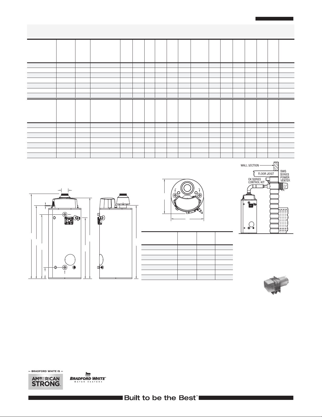
G
Optional Air Intake Ducting Maximum Lengths
B
H
E
M
M
M
L
A
S
C
D
F
G
Commander Series™ Models
Meet or exceed ASHRAE 90.1b (current standard) C.E.C. Listed
NATURAL GAS
Model
Number
UCG-80H-125-3N(A)
UCG-80H-199-3N(A)
UCG-80H-270-3N(A)
UCG-80H-399-3N(A)
UCG-100H-199-3N(A)
UCG-100H-270-3N(A)
UCG-100H-399-3N(A)
Model
Number
UCG-80H-125-3N(A)
UCG-80H-199-3N(A)
UCG-80H-270-3N(A)
UCG-80H-399-3N(A)
UCG-100H-199-3N(A)
UCG-100H-270-3N(A)
UCG-100H-399-3N(A)
Nominal
Gal.
Capacity
U.S.
Gal.
80
80
80
80
100
100
98
Nominal
Liter
Capacity
303
303
303
303
379
379
371
Imp.
Gal.
67
67
67
67
83
83
82
Input
BTU/Hr.
125,000
199,999
270,000
399,999
199,999
270,000
399,999
Input
kW
36.6
58.6
79.1
117.2
58.6
79.1
117.2
GPH Recovery
at Degree Rise*
123
308
197
493
266
665
384
960
197
493
266
665
398
994
LPH Recovery
at Degree Rise*
466
1164
746
1864
1007
2517
1454
3634
745
1866
1006
2517
1476
3757
140°F100°F40°F
141
190
274
141
190
284
78°C56°C22°C
1038
1060
88
333
533
719
533
719
A
Floor
to
Flue
Conn.
in.
15
68
6213/16
6213/16
6815/16
731/4
731/4
777/16
A
Floor
to
Flue
Conn.
mm.
1751
1595
1595
1751
1835
1835
1967
B
Jacket
Dia.
in.
/16
28
28
28
28
28
28
28
B
Jacket
Dia.
mm.
711
711
711
711
711
711
711
C
Vent
Size
in.
5
6
6
8
6
6
8
C
Vent
Size
mm.
127
152
152
203
152
152
203
D
Floor
to
T&P
Conn.
in.
4315/16
4315/16
4315/16
4315/16
523/8
523/8
523/8
D
Floor
to
T&P
Conn.
mm.
1116
1116
1116
1116
1330
1330
1330
E
Floor
to
Gas
Conn.
in.
543/8
543/8
543/8
543/8
627/8
627/8
627/8
E
Floor
to
Gas
Conn.
mm.
1381
1381
1381
1381
1597
1597
1597
F
Floor
to
Top of
Heater
in.
523/16
523/16
523/16
523/16
6011/16
6011/16
6011/16
F
Floor
to
Top of
Heater
mm.
1326
1326
1326
1326
1541
1541
1541
Floor to
Cold Water
Conn./Hot
Water Conn.
54
543/4
543/4
543/4
631/4
631/4
631/4
Floor to
Cold Water
Conn./Hot
Water Conn.
mm.
1391
1391
1391
1391
1607
1607
1607
H
G
in.
3
/4
G
Depth
in.
32
32
32
32
5
29
295/8
295/8
H
Depth
mm.
813
813
813
813
752
752
752
/8
K
Floor to
Cold
Water
Conn.
in.
3
9
/16
93/16
93/16
93/16
913/16
913/16
913/16
K
Floor to
Cold
Water
Conn.
mm.
233
233
233
233
249
249
249
For Propane Gas models change suffix “N” to “X”. Example: UCG-100H-199-3X (UCG-100H-399 available in Natural
Gas only). Natural gas models comply with the latest Ultra Low NOx requirements (14 ng/J or less).
Amp Draw range = 1.0 to 1.8 amps.
(A) ASME - All models are available with ASME construction.
To order ASME construction add the (A) to the end of the model number.
Up to 82% Thermal Efficiency
S
M
L
Floor
to Hot
Water
Conn.
in.
4615/16
4615/16
4615/16
4615/16
537/8
537/8
537/8
L
Floor
to Hot
Water
Conn.
mm.
1192
1192
1192
1192
1368
1368
1368
Water
Conn.
NPT
in.
11/2
11/2
11/2
11/2
11/2
11/2
11/2
M
Water
Conn.
NPT
mm.
38
38
38
38
38
38
38
Gas
Conn.
Size
in.
1
/2
1
/2
1
/2
1
/2
1
/2
1
/2
1
/2
S
Gas
Conn.
Size
mm.
13
13
13
13
13
13
13
Relief
Valve
Open
in.
3
/4
3
/4
1
1
3
/4
1
1
Relief
Valve
Open
mm.
19
19
25
25
19
25
25
Approx.
Shipping
Weight
lbs.
535
535
545
545
632
632
657
Approx.
Shipping
Weight
kgs.
243
243
247
247
286
286
298
Sample Specification
The water heater shall be a Bradford White model UCG-_____ with a rated storage capacity of not less than _____ gallons/ liters, a minimum gas input of __________ BTU/Hr., a minimum
recovery of _____ GPH/LPH at 100°F (56°C) temperature rise, a Thermal Efficiency Rating of _____. It shall be design certified by CSA International (formerly AGA and CGA) for 180°F (82°C)
application, either with or without a separate storage tank. The tank shall be lined with Vitraglas
equipped with stainless steel cold water inlet, Hydrojet
™
ignition system, an ASME rated T&P relief valve and a premix combustion system. The water heater shall be factory assembled and tested. A digital LCD display shall be integrated into
HD
the front and be an adjustable electronic thermostat to any temperature up to 180°F. A recycling Energy Cut Off (E.C.O.) shuts off all gas in the event of an overheat condition. The entire
installation shall be made in compliance with state and local codes and ordinances.
General
All gas water heaters are certified at 300 PSI test pressure (2068 kPa) and 150 PSI working pressure (1034 kPa). All models are design certified by CSA International (formerly AGA/CGA), to
ANSI standard Z-21.10.3, for up to 180°F (82°C) application as an Automatic Storage Heater. As an Automatic Storage Heater, all models are complete, self-contained water heating systems.
It needs no separate storage tank, pump, wiring or elaborate piping network. When equipped with a mixing valve, it can supply 180°F (82°C) sanitizing and lower temperature general purpose
hot water simultaneously. These models can be used either as a single unit or in multiples connected in series or parallel (recommended).
Dimensions and specifications subject to change without notice in accordance with our policy of continuous product improvement.
Model
UCG-80H-125-3(N,X)
UCG-80H-199-3(N,X)
UCG-100H-199-3(N,X)
UCG-80H-270-3(N,X)
UCG-100H-270-3(N,X)
UCG-80H-399-3(N,X)
UCG-100H-399-3N
Optional Honeywell EnviraCOM
closed) when an alarm is present via normally open contacts (rated for up to 24 VAC).
Kit Number – 265-51961-00
®
®
Sediment Reduction System. The heater shall be insulated with Non-CFC foam. This water heater shall be equipped with an ICON
For field service, contact your professional installer or local Bradford White sales representative.
Sales 800-523-2931 n Fax 215-641-1612
Technical Support 800-334-3393
Ambler, PA
Warranty 800-531-2111
International: Telephone 1-215-641-9400 n Email international@bradfordwhite.com / www.bradfordwhite.com
n
vitreous enamel and shall have a bolted hand hole cleanout. This water heater shall be
n
Email techserv@bradfordwhite.com
Email warranty@bradfordwhite.com
©2018, Bradford White Corporation. All rights reserved.
2"
PVC, ABS,
or CPVC
20 ft.
20 ft.
20 ft.
20 ft.
20 ft.
N/A
N/A
™
Alarm Module – Provides indication (contacts are
3"
PVC, ABS,
or CPVC
50 ft.
50 ft.
50 ft.
50 ft.
50 ft.
25 ft.
25 ft.
4"
PVC, ABS,
or CPVC
75 ft.
75 ft.
75 ft.
75 ft.
75 ft.
50 ft.
50 ft.
TYPICAL APPLICATIONS
Optional Power Vent Kits – for side wall
termination only.
Model Numbers Kit Number
UCG-80H-125/199/270,
UCG-100H-199/270: 239-81764-00
UCG-80H-399,
UCG-100H-399: 239-81766-00
Vent Kit
Printed in U.S.A.741-C-0418
 Loading...