

Page 1
INSTALLATION INSTRUCTION - SUPPLEMENT SHEET
HEATING WITH THE SOLAR WATER HEATER WITH GAS BACKUP
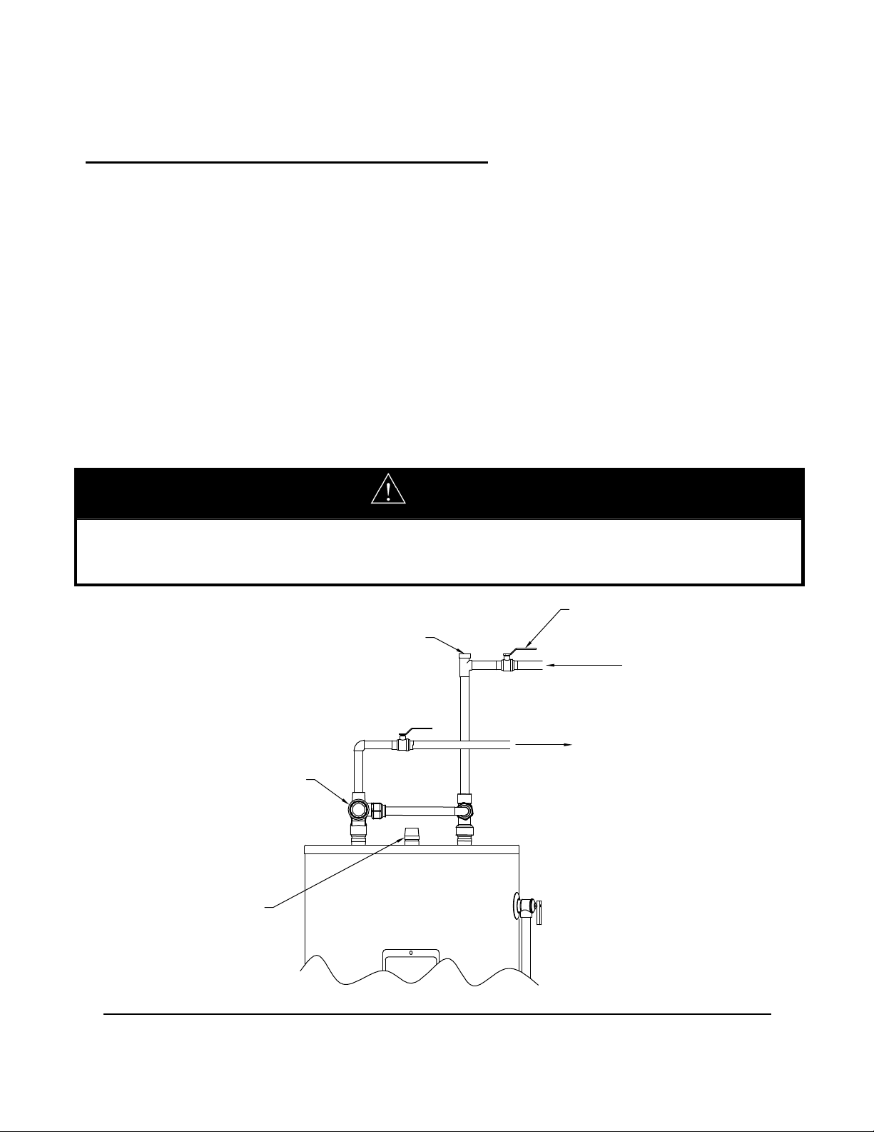
POTABLE AND SOLAR HEATING CONNECTIONS
The water heater interior has been designed for potable water, such as in a solar heating system. If replacing an
existing water heating appliance, be sure to turn off electrical power and/or gas supply to the existing appliance.
Warning: All solar plumbing, connections and components must be applicable for potable water
installations and rated for 150 psi working and 300 psi test pressure.
The solar thermal system connections are identified on the side and top of the appliance. The use of shut off
valves and unions are recommended for future service convenience. Consult local codes for proper use, sizing
and installation of an expansion tank.
Due to the elevated operating temperature that may be obtained with the solar heating system, an ASSE
approved thermostatic mixing valve has been provided and must be installed in the potable water piping
diagram as shown in Figure 1. Directions for proper installation and adjustment are provided in the ASSE
approved thermostatic mixing valve carton.
Warning: Failure to properly install and regulate the provided ASSE approved thermostatic mixing
valve may increase the danger of scald injury and nullify the warranty.
Hotter water increases the risk of scald injury. Scalding may occur within 5 seconds at a setting of 140F. Water
temperature over 125F can cause severe burns or death from scalds. Children, disabled and the elderly are at the
highest risk of being scalded. Please feel the water before bathing or showering.
VACUUM BREAKER
THERMOSTATIC
MIXING VALVE
SOLAR RETURN
FROM COLLECTOR
Figure 1 – Thermostatic Mixing Valve Piping Diagram for Tempered Water (Except 100-Gallon)
DANGER
SHUT-OFF VALVE
COLD WATER
SUPPLY
TEMPERED
POTABLE WATER
238-48283-00B REV 11/10
Page 2
THERMOSTATIC
MIXING VALVE
TEMPERE
POTABLE
VACUUM BREAKER
SHUT-OFF
COLD
SUPPL
SUPPLIED
BUSHINGS & NIPPLES
FROM
Figure 2 – Thermostatic Mixing Valve Piping Diagram for Tempered Water (100-Gallon)
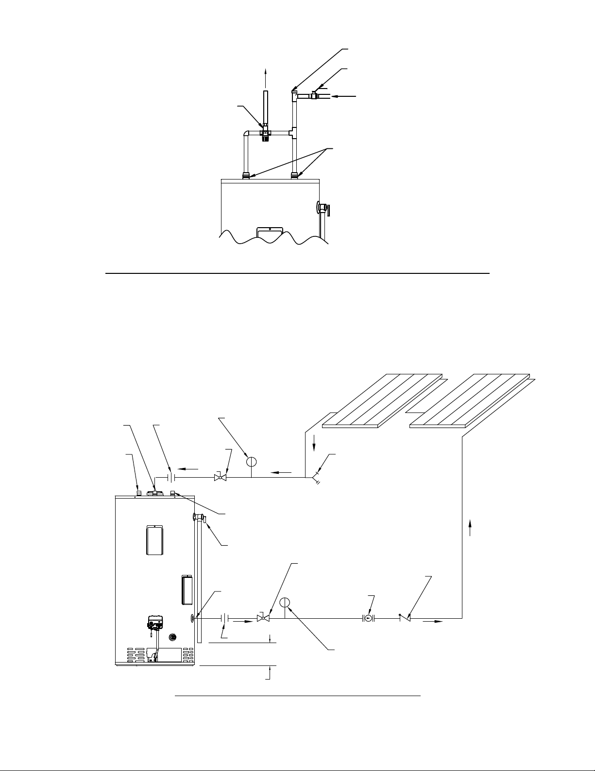
SOLAR HEATING WITH AN OPEN LOOP SYSTEM
1) Pipe the system as shown in figure 3.
2) The temperature and pressure relief valve should be piped to discharge within 6 inches from the floor.
3) The circulator should be installed to pump toward the collector(s) as shown.
4) Purge all air from the filled, open loop system.
DRAIN
VALVE
"FROM SOLAR
COLLECTOR"
POTABLE WATER
CONNECTION
UNION
FULL PORT
BALL VALVE
TEMPERATURE AND
PRESSURE GAUGE
POTABLE WATER
CONNECTION
PRESSURE RELIEF
VALVE (30 PSI)
"TO SOLAR
COLLECTOR"
FULL PORT
BALL VALVE
CIRCULATOR
FLOW CONTROL
VALVE
UNION
6" FROM
FLOOR
TEMPERATURE AND
PRESSURE GAUGE
Figure 3 – Solar Heating with an Open Loop System
Page 3

SENSOR WIRES FOR SOLAR THERMISTOR CONNECTIONS – Twisted wires are provided under the
lower and upper covers. These wires have been provided as a means for connecting thermistors to a solar
controller. NOTICE: Neither the solar controller nor the thermistors are provided with the solar water
heater and must be purchased separately. The lower thermistor wires connect a thermistor for use in
comparison to the solar collector temperature to determine if an appropriate temperature difference for heat
transfer is available. A bracket to fix the thermistor against the tank wall is supplied. The upper thermistor
wires are an optional second thermistor connection to monitor the upper tank temperature. Some solar
controllers provide this option.
ORANGE WIRE
WIRE NUTS
THERMISTOR
(NOT INCLUDED)
SENSOR PLATE
BRACKET
COVER
OPENING
Figure 4 – Wiring and Placement for the Solar Control Temperature Sensor
WIRE NUTS
BROWN WIRE
THERMISTOR
(NOT INCLUDED)
SENSOR PLATE
BRACKET
3/4" SPUD3/4" SPUD
COVER
OPENING
 Loading...