

Bradford White RG2F40S6N, RG2F50S6N Installation Manual
SUPER HIGH EFFICIENCY WATER HEATERS
CONGRATULATIONS!
of your water heat er in the maintenance sect ion in t he back of t his manual.
SUPPLEMENT TO INSTRUCTION MANUAL
P/N 238-51012-00
(Replaces pg. 2 in instruction manual.)
You have just purchased one of t he f inest water heaters on the market
today!
This installation, operation and inst ruct ion m anual w ill explain in detail the
installation and maintenance of y our new High Ef f iciency Flam m ab le Vap o r
Ignition Resistant Gas Water Heater. W e strongly recommend that y ou
cont act a plumbing prof essional for the inst allation of t his water heater.
W e req u ir e that yo u c areful ly r ead th i s m an u al, as well as the en c lo sed
w arranty , and refer to it when quest ions arise. If y ou have any specif ic
questions concerning your warranty , please consult the plumbing
prof essional from whom your water heater w as purchased. For your records,
w e recommend t hat y ou write t he model, serial number and installation dat e
Special Flammable Vapor Ignition Resistant System:
Th is water h eat er is equipped w it h a Flammable Vapor Ignit ion Resistant Syst em.
In the event of im proper usage or storage of gasoline or other f lammable materials
in t he location where the water heater is installed, t he technology will resist
ignit ion of t he f lammable vapors outside the conf ines of t he wat er heater.
The Flammable Vapor Ignition Resistant Syst em Features:
• A dvan c ed Flam e A r r estor D esi gn
• Re-set t able Thermal Switch to prevent burner/pilot operation wit h
restri c ted ai rflo w
• Flamm ab l e V ap or Sen so r
• Aut om atic Ignit ion Device
• Sight Wi ndow to observe operation of pilot and burner
FO R Y O UR S AFET Y: A ct iv at ion of t he Flammable Vapor Ignit ion Resistant Syst em
oc c u rs when flam m abl e v ap o r s are d r awn i n to th e w ater heater an d are
co m b us ted . I f f l am m ab le vap o rs ar e d etected:
• Do not try t o light any appliance.
• Do not touc h any electrical sw it c h; do not use any phone in your building.
• Leave the p r em is es an d i m m ed i atel y c al l th e fir e dep ar tm en t f r o m a
neighbor’s phone. Follow the f ire department’s instruct ions.
Onc e the fl ammable vapor has been evacuated, contact y our plumbing
prof essional or the manufact urer f or f urt her inst ruct ions. Replacement of a
Flammable Vapor Ignition Resistant Syst em equipped wat er heat er due to a
f lammable vapor shutdown is not c overed under the t erm s of th e l im i ted war ran ty.
238-51003-00B REV 6/18
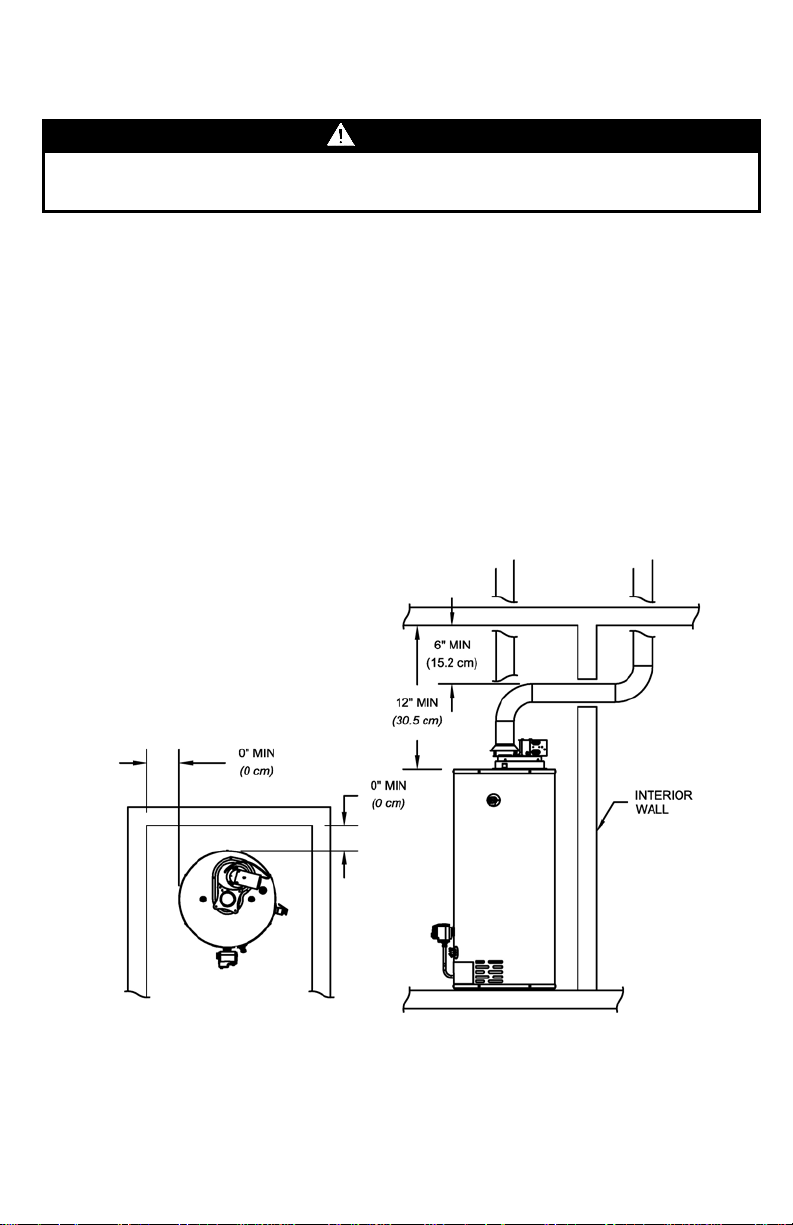
Minimum Clearances
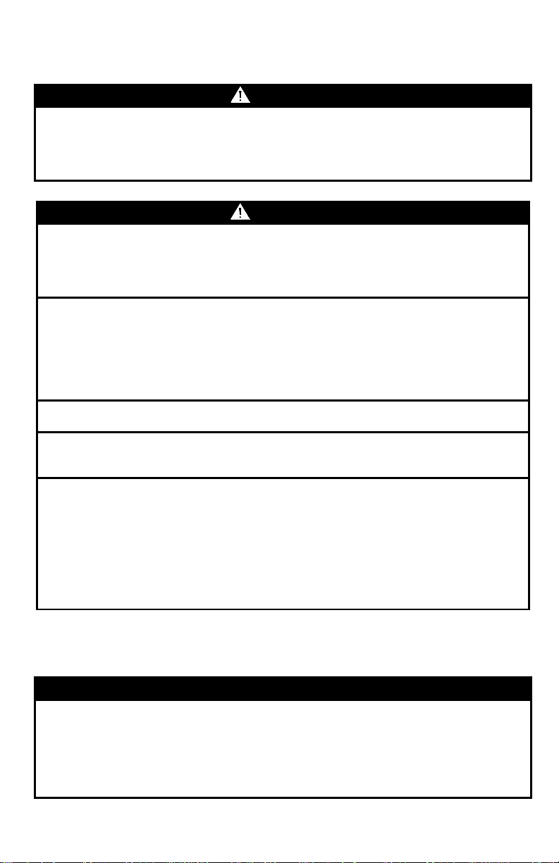
WARNING
Failure to adhere to these installation and operating instructions may create a hazard
(Replaces pg. 9 in instruction manual.)
to life and property and will nullify the warranty.
This installation must allow access to the front of the water heater and adequate
clearance must be provided for servicing and operating this water heater. The water
heater may be installed on either a combustible or non-combustible floor. If the water
heater is to be installed directly on carpeting, it must be installed on top of a metal or
wood panel (or equivalent) extending beyond the full width and depth of the water
heater by at least 3 in. (7.6 cm) in any direction or, if the appliance is to be installed in
an alcove or closet, the entire floor must be covered by the panel. If the rating plate or
the label on the front of the heater specifies minimum clearances less than those
listed below, the water heater must be installed in accordance with the minimum
clearances listed on the rating plate or the label on the front of the heater.
If it is necessary to install this water heater in an alcove, use the clearances listed in
Figure 1.
Figure 1. Minimum Clearances for an Alcove Installation.
2
Venting
WARNING
The venting system must be installed properly following all local codes or in the
in property damage, personal injury, or death.
WARNING
Carefully inspect the venting system of a replacement water heater installation
good condition.
The chimney must be lined and in good condition. Check to make sure the venting
venting with another gas appliance.
Do not vent this water heater into the venting system of another gas appliance
designed to vent under positive pressure.
The water heater should be installed as close as practical to the venting system to
limitations on vent connector lengths.
At the completion of the water heater installation, the burner and venting system
Operation”.
NOTICE
This water heater is equipped with a draft hood. This water heater can be vented
columns to determine appropriate vent configuration.
(Replaces pg. 10 in instruction manual.)
absence of local codes, the latest edition of the National Fuel Gas Code (ANSI
Z223.1- latest edition), or in Canada, The Natural Gas and Propane Installation Code
(B149.1-00 latest edition). Failure to properly install the venting system could result
before connecting to the venting system. All joints in the vent connector must be
securely fastened with screws and fit tightly together. Inspect the venting system for
signs of deterioration (rust and perforation) and replace any sections that are not in
system is properly sized for the water heater. If the venting system was previously
sized for another gas appliance that has been removed, the venting system may
now be too large. Refer to the latest edition of the National Fuel Gas Code (ANSI
Z223.1-latest edition), or in Canada, the Natural Gas and Propane Installation Code
(B149.1-00 latest edition) for the correct sizing of venting systems and common
minimize the vent connector length required. Refer to local codes for the distance
must be checked for proper operation with all other commonly vented appliances in
operation. Check for spillage of flue products around the outside relief opening of
the draft hood after several minutes of operation. The flame from a match should be
drawn into the draft hood. Do not use the water heater or connected equipment if
spillage is detected until the problem is corrected. Refer to the latest edition of the
National Fuel Gas Code, or in Canada, the Natural Gas and Propane Installation
Code for complete details on the “Procedure to Be Followed to Place Equipment in
This water heater has been shipped with a draft hood for which it was designed with reference to the horizontal and vertical planes. If removed, the draft hood must be replaced in the same position and secured to the blower draft hood bracket.
using single wall or double wall vent connector pipe. This water heater may be
vented into Type B vent or a masonry chimney. This water heater can use either 3”
or 4” venting.
Refer to the National Fuel Gas Code (latest edition) vent tables, using “NAT”
3
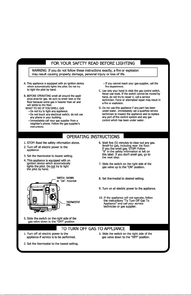
Lighting and Shutdown Instructions
(Replaces pg. 18-19 in instruction manual.)
4
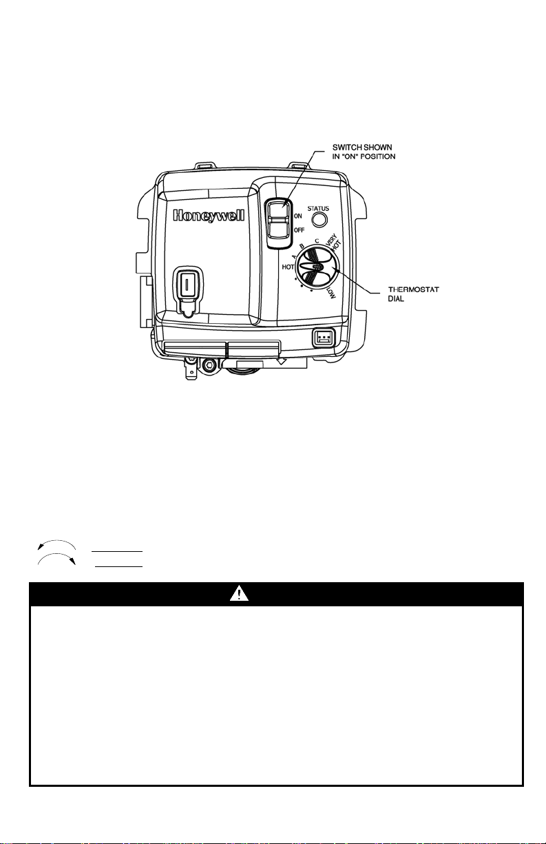
THERMOSTAT ADJUSTMENT
DANGER
Hotter water increases the risk of scald injury. Scalding may occur within five (5)
(Replaces pg. 20-21 in instruction manual.)
The thermostat dial is adjusted to its lowest setting when shipped from the factory.
When adjusting the thermostat, it should be remembered that lower temperature
settings are more energy efficient. To adjust the thermostat, turn the dial clockwise
until the minimum acceptable temperature is set. It is suggested that the starting point
setting not exceed the 120°F (49°C) or “HOT” setting on the thermostat.
NOTE: Taupe / Silver faceplate is approximately 160ºF maximum set point. Dark
(Battleship) Grey faceplate is approximately 180ºF maximum set point.
The thermostat dial is set t o it s lowest t emperature setting when shipped from t he
f ac tor y . Remem b er th at lo wer temp er atu r e sett i n gs are m o r e ener g y eff i c i ent.
Adjust t he t emperature by t urning t he t hermostat dial. It is suggested that the
start ing point setting not be greater than t he ‘‘Hot’’ mark on t he t hermostat dial
(app r oxi m ately 120 ° F [48.9°C]). Ro tat e the therm o stat d i al counter-clockwise
to decrease th e temp er atu r e sett i n g. Rotat e the therm o stat d i al c lo c k w i se
to increase t he t emperature setting. A djust t he dial until the minimum
acc ep table temp er ature i s ac h i ev ed .
seconds at a temperature setting of 140°F (60°C). To protect against hot water injury,
install an ASSE approved mixing valve in the water system. This valve will reduce
point of discharge temperature by mixing cold and hot water in branch water lines. A
licensed plumbing professional or local plumbing authority should be consulted.
Note: This water heater is equipped with an energy cut out device to prevent
overheating. Should overheating occur or the gas supply fails to shut off, turn off the
manual gas control valve to the water heater, and call a qualified service technician.
Note: Whenever the water heater is filled with cold water, condensate will form on the
cool tank surface and drops of water will fall on the hot burner and combustion
chamber surfaces producing a “sizzling” noise. Condensation is normal and does not
indicate a leak. It will disappear when the tank becomes heated.
Figure 2. Gas Valve.
5
 Loading...