

Page 1
Flammable Vapor Ignition Resistant
Water Heaters
Direct Vent Water Heaters
SERVICE
MANUAL
Troubleshooting Guide
and Instructions for Service
(To be performed ONLY by
qualified service providers)
Manual 238-51636-00C REV 08/19
Models Covered
by This Manual:
RG2DV40S*(N,X)
RG2DV50S*(N,X)
RG2DV50H*(N,X)
LG2DV50H50*(N,X)
(*) Denotes Warranty Years
Save this manual for future reference
Page 2

The Bradford White
DV Series
Direct Vent Water Heaters
Page SVC Procedure
Introduction ................................................................................4 ---
Tools Required for Service ........................................................5 ---
Troubleshooting Charts .............................................................6 ---
Inner Door Removal and Replacement ....................................12 I
Thermocouple/Thermopile Testing ...........................................15 II
Igniter, Electrode Testing, and Replacement ...........................18 III
Gas Control Testing and Replacement ....................................19 IV
Burner Inspection, Cleaning, and Replacement ......................34 V
Pilot Testing, Cleaning, and Replacement ...............................36 VI
Resettable Thermal Switch Testing and Replacement ...........37 VII
Table of Contents
Diptube Inspection and Replacement ......................................39 VIII
Anode Inspection and Replacement ........................................40 IX
Glossary of Terms .....................................................................41 ---
Parts Diagram ............................................................................42 ---
Notes ..........................................................................................43 ---
2
2
Page 3
DV Series
DANGER
DO NOT store or use gasoline or
vicinity of this or any other appliance
.
WARNING
DO NOT ATTEMPT TO LIGHT ANY GAS APPLIANCE IF
plumbing professional, for more information.
WARNING
FAILURE TO INSTALL AND MAINTAIN A NEW, LISTED
TEMPERATURE AND PRESSURES.
CAUTION
If sweat fittings are to be used DO NOT apply heat to the
a plastic liner.
WARNING
Hydrogen gas can be produced in an operating water
open flame near the faucet at the time it is open.
WARNING
Water heaters are heat producing appliances. To
SYSTEM.
WARNING: If the information in these
instructions is not followed exactly, a fire or
explosion may result causing property damage,
personal injury, or death.
Do not store or use gasoline or other flammable,
combustible, or corrosive vapors and liquids in the
vicinity of this or any other appliance.
WHAT TO DO IF YOU SMELL GAS:
x DO NOT try to light any appliance.
x DO NOT touch any electrical switch; do not use any
phone in your building.
x Immediately call your gas supplier from a neighbor's
phone. Follow the gas supplier's instructions.
x If you cannot reach your gas supplier, call the fire
department.
Installation and service must be performed by a qualified
installer, service agency or the gas supplier.
FOR YOUR SAFETY
other flammable, combustible, or
corrosive vapors and liquids in the
IMPORTANT
Before proceeding, please inspect the
water heater and its components for
possible damage. DO NOT install any
water heater with damaged
components. If damage is evident
then please contact the supplier where
the water heater was purchased or the
manufacturer listed on the rating plate
for replacement parts.
avoid damage or injury, do not store materials against
the water heater or vent-air intake system. Use proper
care to avoid unnecessary contact (especially by
children) with the water heater and vent-air intake
components. UNDER NO CIRCUMSTANCES
SHOULD FLAMMABLE MATERIALS, SUCH AS
GASOLINE OR PAINT THINNER BE USED OR
STORED IN THE VICINITY OF THIS WATER
HEATER, VENT-AIR INTAKE SYSTEM OR IN ANY
LOCATION FROM WHICH FUMES COULD REACH
THE WATER HEATER OR VENT-AIR INTAKE
heater that has not had water drawn from the tank for a
long period of time (generally two weeks or more).
HYDROGEN GAS IS EXTREMELY FLAMMABLE. To
prevent the possibility of injury under these conditions,
we recommend the hot water faucet to be open for
several minutes at the kitchen sink before you use any
electrical appliance which is connected to the hot water
system. If hydrogen is present, there will be an
unusual sound such as air escaping through the pipes
as hot water begins to flow. DO NOT smoke or have
YOU ARE NOT CERTAIN OF THE FOLLOWING:
x Liquefied petroleum gases/propane gas and natural
gas have an odorant added by the gas supplier that
aids in the detection of the gas.
x Most people recognize this odor as a “sulfur” or
“rotten egg” smell.
x Other conditions, such as “odorant fade” can cause
the odorant to diminish in intensity, or “fade”, and not
be as readily detectable.
x If you have a diminished sense of smell or are in any
way unsure of the presence of gas, immediately
contact your gas supplier from a neighbor’s
telephone.
Gas detectors are available. Contact your gas supplier, or
3/4” X 3/4” TEMPERATURE AND PRESSURE RELIEF
VALVE WILL RELEASE THE MANUFACTURER FROM ANY
CLAIM THAT MIGHT RESULT FROM EXCESSIVE
nipples on top of the water heater. Sweat the tubing to the
adapter before fitting the adapter to the water connections. It
is imperative that heat is not applied to the nipples containing
3
3
Page 4

DV Series
Introduction
The new Bradford White DV water heaters are designed to provide reliable performance with
enhanced standard features. Design features include reliable standing pilot ignition system,
enhanced diagnostics, simplified servicing, and certified FVIR technology.
The DV water heaters use a combustion system where combustion air is drawn from the
outside of the building. The gas control maintains water temperature and gas flow. If a
situation outside of the normal operating parameters exists, the gas control diagnostic LED will
flash a code to identify an operational issue.
This service manual is designed to facilitate problem diagnosis and enhance service efficiency.
Please read the service manual completely before attempting service on this series of direct
vent water heaters.
How the Safety System Works
During normal operation, air for combustion is drawn into the water heater through the openings
in the jacket. This air travels down and around the combustion chamber and enters through the
back of the corrosion resistant combustion chamber. The air then mixes in a normal manner
with supplied gas and is efficiently combusted, producing very low NOx emissions.
4
4
Page 5

DV Series
Manometer:
A liquid “U” tube type or a digital (magnahelic) type can be
and vacuum.
Multi-Meter:
A digital type is strongly recommended. This device is used
micro-amps, and ohms.
Electronic Probes:
In some cases, standard multi-meter probes will damage or
electronic wholesale outlets.
Thermometer:
Used to measure water temperature. An accurate
thermometer is recommended.
Water Pressure Gage:
Used to measure water supply pressure. Also used to
heater.
Various Hand Tools:
Pipe wrench, channel locks, open end wrenches (3/8”, 7/16”,
flashlight, and 5-gallon pail.
It is intended for this manual to be used by qualified service personnel for the primary
purpose of troubleshooting and repair of the Bradford White DV Series water heaters.
The Honeywell Icon Gas Control will display status codes in the event of abnormal
operation. Status codes are listed in the troubleshooting charts beginning on page 6 of
this service manual. The troubleshooting charts on page 6 will also indicate the
probable cause for the status code and direct the service professional to a service
procedure to properly diagnose the abnormal operation.
In some difficult to diagnose conditions, it may be necessary to isolate the heater from
the vent system to determine the problem.
Contact the Bradford White technical support group immediately if diagnosis cannot be
made using the methods described in this service manual.
Tools Required for Service
used. This device is used to measure gas and/or air pressure
to measure electrical values. The meter you select must have
the capability to measure volts AC, volts DC, amps,
simply not be effective to obtain certain voltage and ohm
readings. It will be necessary to have special electronic “pin”
type multi-meter probes. These probes are available at most
determine tank pressure by adapting to the drain valve of the
1/2”), 12” crescent wrench, allen wrench set, screw drivers
(common & Phillips), 1/4” nut driver, pliers (common & needle
nose), socket set, side cutters, wire cutters, wire strippers,
wire crimpers, torpedo level, small shop vacuum, step ladder,
5
5
Page 6
DV Series
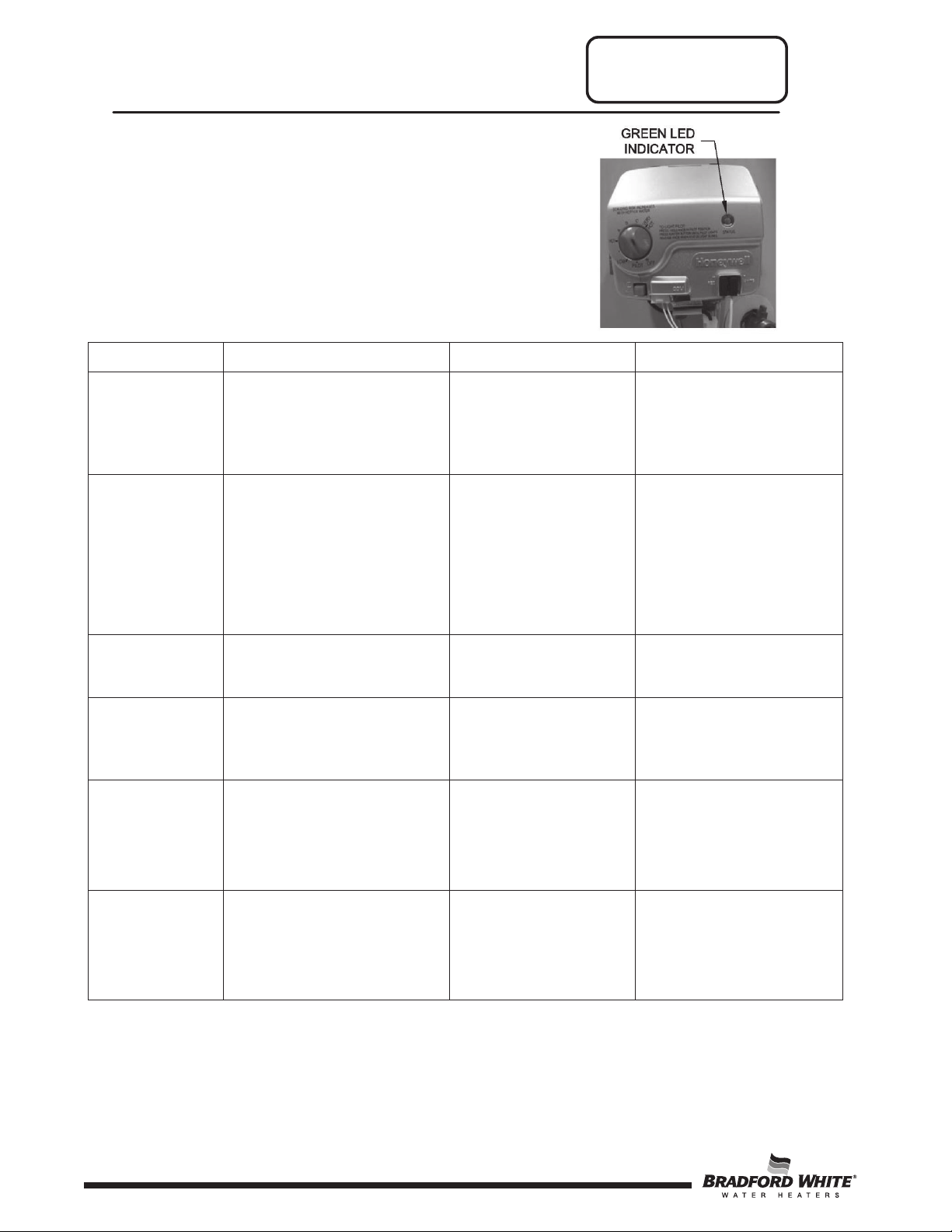
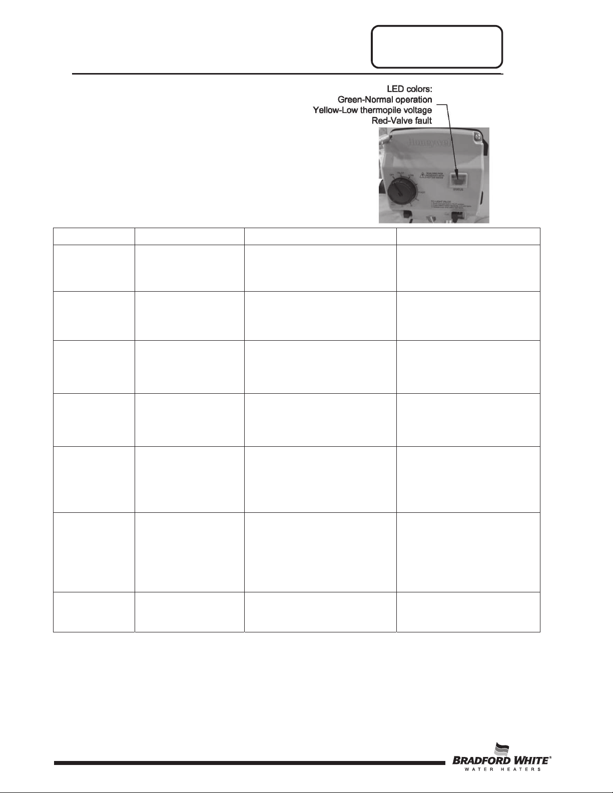
LED Status
Control Status
Probable Cause
Service Procedure
If the pilot will not stay
control.
1.
If setpoint knob is in
is satisfied.
Setpoint knob has been
out before attempting to relight.
LED will go out and the
lit.
2. See Service Procedure VI
3. See Service Procedure VI
Troubleshooting Gas
Control V1
Observe green LED indicator on
electronic gas control. Status flash
codes are displayed with a three second
pause before repeating. Check and
repair the system as noted in the
troubleshooting table below.
None (LED not
on or flashing)
One flash and
three second
pause
Short flash once
per second
LED on
continuously
(solid)
Two flashes and
three second
pause
Pilot assembly is not lit.
“PILOT” position then pilot
flame is detected. Turn
setpoint knob to desired
setting.
2.
If the setpoint knob is
already at
setting, the water
Gas control is calling for heat
(no fault).
recently turned to the “OFF”
position. Wait until LED goes
Weak pilot signal detected.
System will reset when pilot
flame is sufficient.
the desired
heater
Gas control is not
powered. Light pilot.
1.
Gas control is
powered and waiting
for setpoint knob to be
turned to a water
temperature setting.
2.
Water heater is
satisfied and operating
normally.
Tank temperature below
setpoint of thermostat.
Setpoint knob was turned
to “OFF” position.
1.
Thermopile failure.
2.
Unstable pilot.
3.
Pilot tube blocked or
restricted.
lit replace pilot
assembly. If problem
persists replace gas
Normal operation.
Normal operation.
control will function
normally once the pilot is
1. See Service
Procedure II
Three flashes
and three second
pause
6
Insuffcient water heating.
System will reset.
1.
Thermal sensor out of
calibration.
2.
Faulty gas control.
6
Replace gas control.
Page 7
DV Series
LED Status
Control Status
Probable Cause
Service Procedure
Four flashes
1.
Damage to the
range.
physically damaged.
Eight flashes
Standing pilot remains on while
Troubleshooting Gas
Control V1
Observe green LED indicator on
electronic gas control. Status flash
codes are displayed with a three second
pause before repeating. Check and
repair the system as noted in the
troubleshooting table below.
and three
second pause
Excessive tank temperature.
System must be reset.
1.
Temperature sensor
out of calibration.
2.
Faulty gas control.
Replace gas control.
Five flashes
and three
second pause
Seven flashes
and three
second pause
and three
second pause
Temperature sensor fault.
Gas control electronic fault
detected.
setpoint knob is in “OFF”
position.
temperature sensor.
2.
Temperature sensor
resistance out of
1.
Control needs to be
reset.
2.
Control is wet or
Pilot valve stuck in
open position.
Replace gas control.
1. Reset gas control.
2. Replace gas control.
Replace gas control.
7
7
Page 8
DV Series
LED Status
Control Status
Probable Cause
Service Procedure
If the pilot will not stay lit
control.
One flash every
None. Control will automatically
setpoint temperature.
Two flashes
(LED yellow)
voltage;
Check the valves and the water
if exceeding setpoint.
Check water temperature
elements.
Not an error–indicates
OFF position.
LED will go out and the
once the pilot is lit.
Troubleshooting Gas
Control V2
Observe colored LED indicator on
electronic gas control. Status flash
codes are displayed with a three second
pause before repeating. Check and
repair the system as noted in the
troubleshooting table below.
None (LED not
on or flashing)
four seconds
(LED green)
One flash every
second
(LED green)
and three
second pause
Four flashes
and three
second pause
(LED red)
Five flashes
and three
second pause
(LED red)
Millivolt power is not
present. Light pilot.
Not an error. Indicates
pilot is lit and main
burner is off.
Not an error. Indicates
main valve is open
and main burner is lit.
Low thermopile
main valve not turned
on.
Temperature cut-out
limit reached, causing
shutdown.
Electronics, sensor, or
gas valve fault
detected.
Gas valve is functioning
normally. Gas valve is not
powered. Light pilot.
The knob can be turned to a
desired setpoint temperature.
shut main burner off when water
temperature reaches the
Check thermopile and its
connections. Check pilot flame.
temperature sensor. Reduce
the water temperature setpoint.
Verify control operation, replace
sensor and its connection for
open circuits, shorts, or
differences in resistance
between the two sensor
replace pilot assembly. If
problem persists replace gas
Normal operation.
Normal operation.
1. See Service Procedure II
2. See Service Procedure VI
Replace gas control.
Replace gas control.
Solid ON
(LED red)
8
that the control is in
None; wait until LED turns off to
restart system.
8
control will function normally
Page 9
DV Series
Troubleshooting Gas Control
White Rodgers Mechanical
Service Procedure
6.
Piezo igniter not functioning.
gas
1.
switch located on inner door.
the
will
necessary.
Symptom Probable Cause Corrective Action
1.
No incoming gas or too low
1.
Turn on gas supply and/or check
pressure.
line
2.
Review lighting instruction. Set
control knob to
3.
Review lighting instruction. Fully
depress gas control knob.
4.
Clean, repair or replace.
5.
Verify correct electrode position.
Replace pilot assembly.
6.
Replace piezo igniter.
Check connection at combination
thermostat/gas valve. Proper
tightness should be finger tight
+ a 1/4 turn.
2.
Inspect thermocouple to ensure
that it is fully engaged into pilot
bracket.
3.
Clean pilot orifice and verify pilot
tube is clear; check gas supply
and line pressure.
4.
Check thermocouple and replace
if necessary.
5.
Check ECO continuity and replace
combination thermostat/gas valve
if necessary.
6.
Check magnet operation and
replace combination
thermostat/gas valve if necessary.
7.
Determine cause of switch
activation. To reset, depress
button on resettable thermal
correct position.
Pilot will not
light
Pilot will not
stay lit when
button is
released
gas
pressure.
2.
Gas control knob set to
position.
wrong
3.
Gas control knob not being
depressed when
fully
attempting to light
4.
Pilot orifice or pilot tube is
obstructed
5.
Pilot electrode not sparking to
pilot.
1.
Poor thermocouple
connection at
thermostat/gas valve.
2.
Thermocouple not fully
engaged in
bracket.
3.
Pilot flame is not fully
enveloping the
bulb.
4.
Weak or defective
thermocouple.
5.
Open ECO in
combination
gas valve.
6.
Defective magnet in
combination
valve.
7.
Resettable thermal switch
has
opened.
pilot.
or kinked.
combination
pilot assembly
thermocouple
thermostat/
thermostat/gas
1.
See Service
2.
3.
4.
1.
2.
3.
Procedure
See Service
Procedure
See Service
Procedure
See Service
Procedure
See Service
Procedure II
See Service
Procedure IV
See Service
Procedure IV
IV
V
V
III
I
I
Pilot will light but
main burner
not come on
1.
Combination thermostat/gas
valve set too
water temperature.
2.
Combination
thermostat/gas valve
temperature is satisfied.
3.
Insufficient gas supply or
low gas
4.
Combination thermostat/gas
valve has
is out of calibration.
low for desired
pressure.
wide differential or
1.
Adjust temperature dial on
combination thermostat/gas
valve.
2.
Check temperature dial
setting on combination
thermostat/gas valve.
3.
Check gas supply and line
pressure.
4.
Check combination
thermostat/gas valve for
proper operation, replace if
1.
See Installation
and Operation
Manual.
2.
See Service
Procedure IV
3.
See Service
Procedure IV
9
9
Page 10

DV Series
Troubleshooting Gas Control
White Rodgers Mechanical
Service Procedure
Symptom Probable Cause Corrective Action
1.
Verify adequate combustion air
Pilot goes out
periodically (after
heating cycles,
once a day, once
a week etc.)
Not enough hot
water
1.
Insufficient combustion air
supply.
2.
Incorrect or clogged vent
system/vent terminal, or
incorrect location.
3.
Inconsistent gas supply or
gas pressure.
1.
Combination thermostat/gas
valve set too low for desired
water temperature.
2.
Cold inlet water temperature
is very cold.
3.
High demand periods.
4.
Incorrectly sized water
heater for application.
5.
Combination thermostat/gas
valve is out of calibration/not
functioning.
6.
Out of spec dip tube is
diluting hot water with cold
water.
is available
and clear jacket slot
any dirt, dust, restrictions or
other obstructions. Inspect flame
arrestor
bristled brush
air to remove any debris
accumulation.
2.
Check venting for proper sizing
and proper
3.
Check gas supply and line
pressure.
1.
Check dial on combination
thermostat/gas
2.
Extremely cold water going into
the heater
amount of hot water
may be necessary to temper
incoming water supply.
3.
Adjust high demand usage.
4.
Contact plumbing professional.
5.
Check combination
thermostat/gas valve
operation, replace if
6.
Inspect dip tube and replace if
necessary.
to the unit. Check
plate and clean with stiff
and compressed
operation.
valve.
will decrease the
openings of
produced. It
for proper
necessary.
1.
See Service
Procedure VII
2.
See Service
Procedure IV
1.
See Service
Procedure IV
10
10
Page 11
DV Series
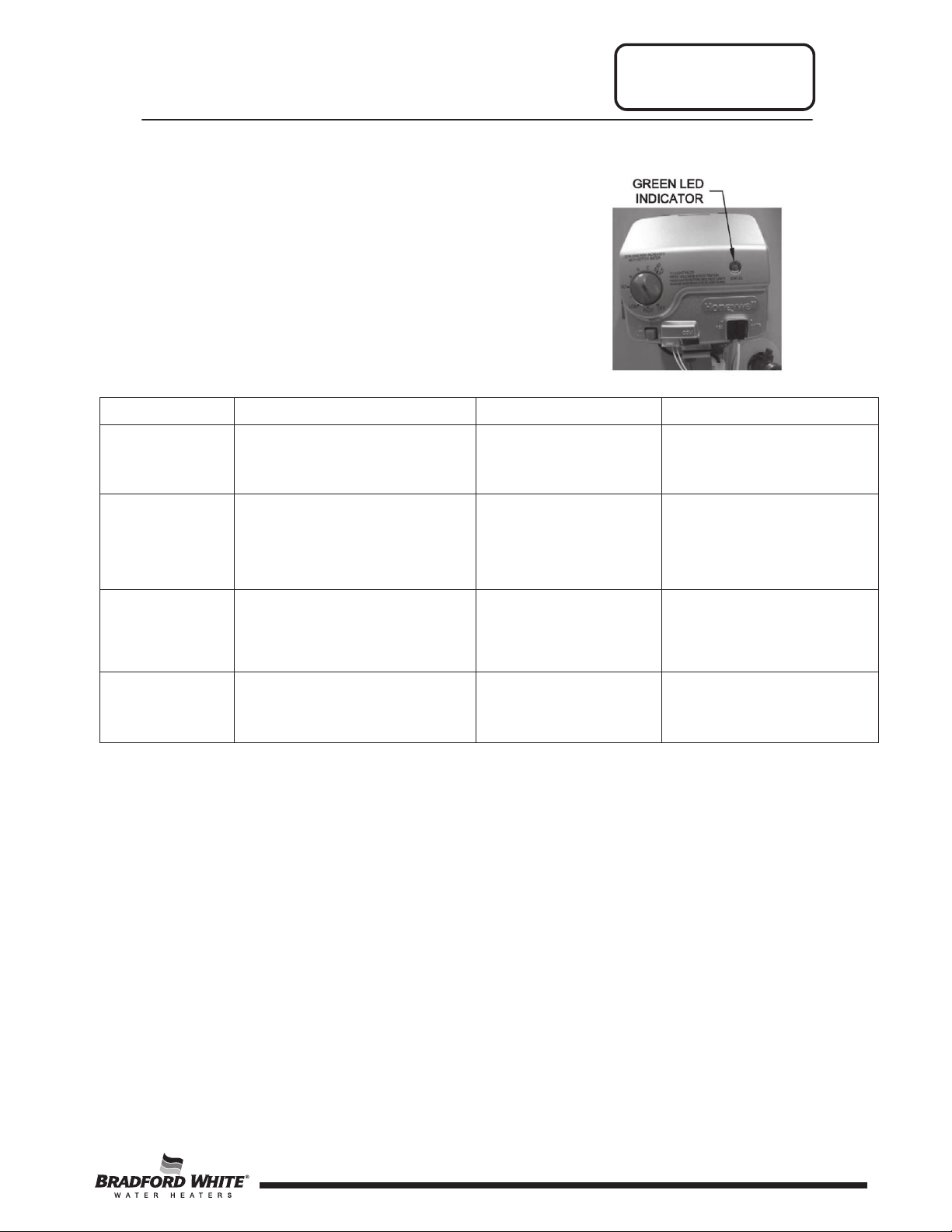
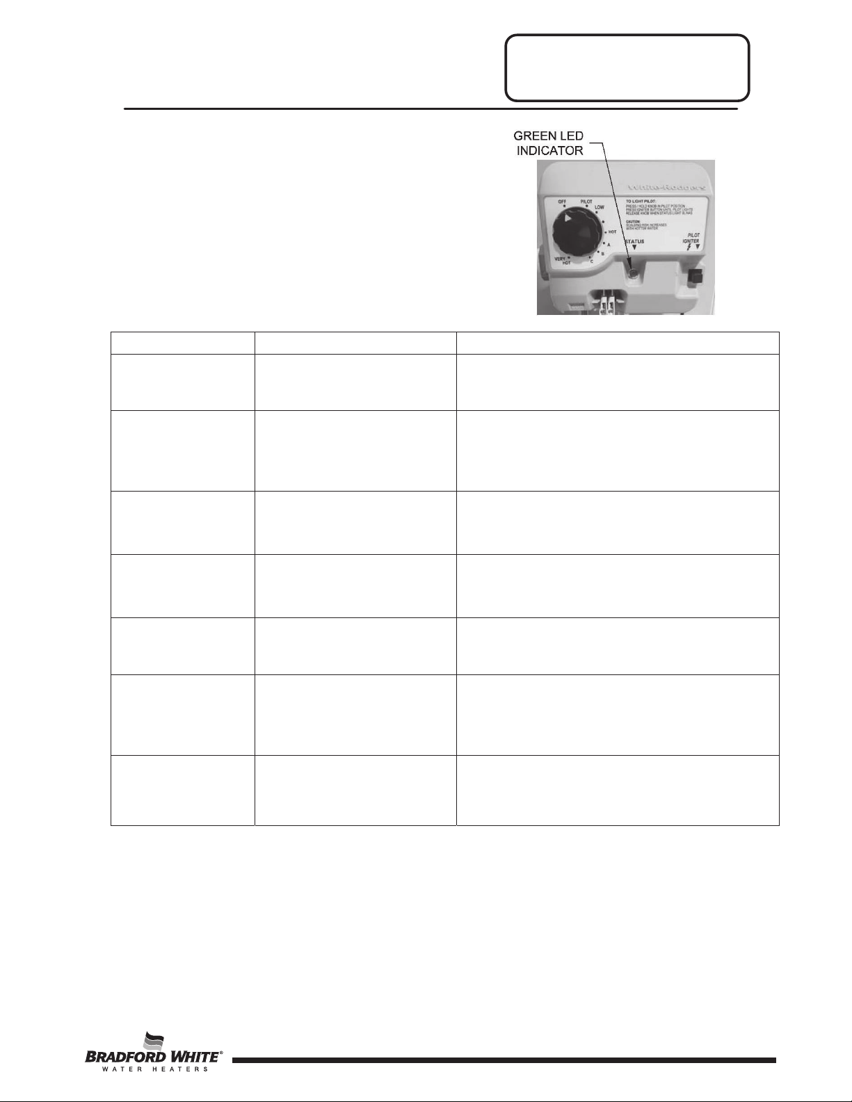
Observe green LED indicator on gas
LED Status
Control Status
Probable Cause
Indicates control is off.
off.
Gas valve is powered and waiting for the set
setting, the thermostat is satisfied.
Not an error. Indicates main
Not an error. Indicates that
Two flashes and
pause
Excessive temperatures may have been
control. Status flash codes are displayed
with a three second pause before repeating.
Check and repair the system as noted in the
troubleshooting table below.
Troubleshooting Gas Control
White Rodgers Electronic
None (LED not on
or flashing)
One flash every
four seconds
One flash every
second
Solid ON
three second
Four flashes and
three second
pause
Five flashes and
three second
pause
Main and pilot burner are
Not an error. Indicates pilot
is lit and main burner is off.
valve is open and main
burner is lit.
the control is in shutdown
mode.
Low thermopile voltage;
main burner not lit.
Temperature cut-out limit
reached causing shutdown.
Electronics, sensor, or gas
valve fault detected.
Gas valve is functioning normally. Gas valve
is not powered. Light pilot.
point knob to be turned to a water temperature
setting. If the set point knob is at desired
Thermostat is calling for heat. Water heater
operating normally and is in heat cycle.
Set point knob was recently turned to “OFF”
position. Wait until LED goes out before
attempting to relight.
Loose thermopile connections or weak pilot
flame.
reached. Shut off the control and reduce the
water temperature. Thoroughly verify control
operation, replace if exceeding setpoint.
Control may be wet or damaged. Verify all
connections are tight; if problem persists
replace the control.
11
11
Page 12
DV Series
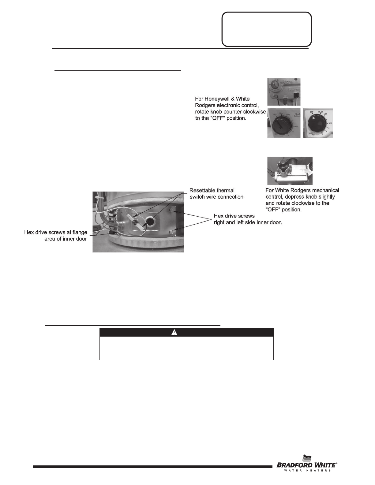
WARNING
If the information in these instructions is not followed
damage, personal injury, or death.
Service Procedure I
Inner Door Removal and
Replacement
Inner Door Removal Procedure
Step 1. Rotate the gas control knob to the
“OFF” position.
Step 2. Remove the outer jacket burner access
door.
Step 3. Remove the wire clip from the feedline
(if present).
Step 4. Remove two (2) 1/4” hex drive screws from the
right side inner door.
Step 5. Remove two (2) 1/4” drive screws from the
flange area of the inner door.
Step 6. Remove two (2) 1/4” drive screws from the left
side inner door.
Step 7. Remove the inner doors and inspect per Step 4.
Step 8. Fully inspect inner door gaskets for the following:
●Tears ●Other imperfections that will inhibit proper seal
●Missing material ●Gasket adhesion to inner door
●Cracks ●Material left on combustion chamber (around opening)
●Dirt or debris
If the gasket is not affected by any of the above, gasket replacement is not required. If
replacement is required, proceed to Inner Door Gasket Replacement Procedure.
Inner Door Gasket Replacement Procedure
Step 1. After inspection of inner door as noted in Step 8 of “Inner Door Removal Procedure,"
completely remove gasket and adhesive residue from right and left side inner doors as
needed.
exactly, a fire or explosion may result causing property
12
12
Page 13
WARNING
Stripped fastener connections may allow for
over tighten screws in steps 2, 3 and 4.
Service Procedure I
Inner Door Removal and
Replacement
DV Series
Inner Door Gasket Replacement Procedure (cont.)
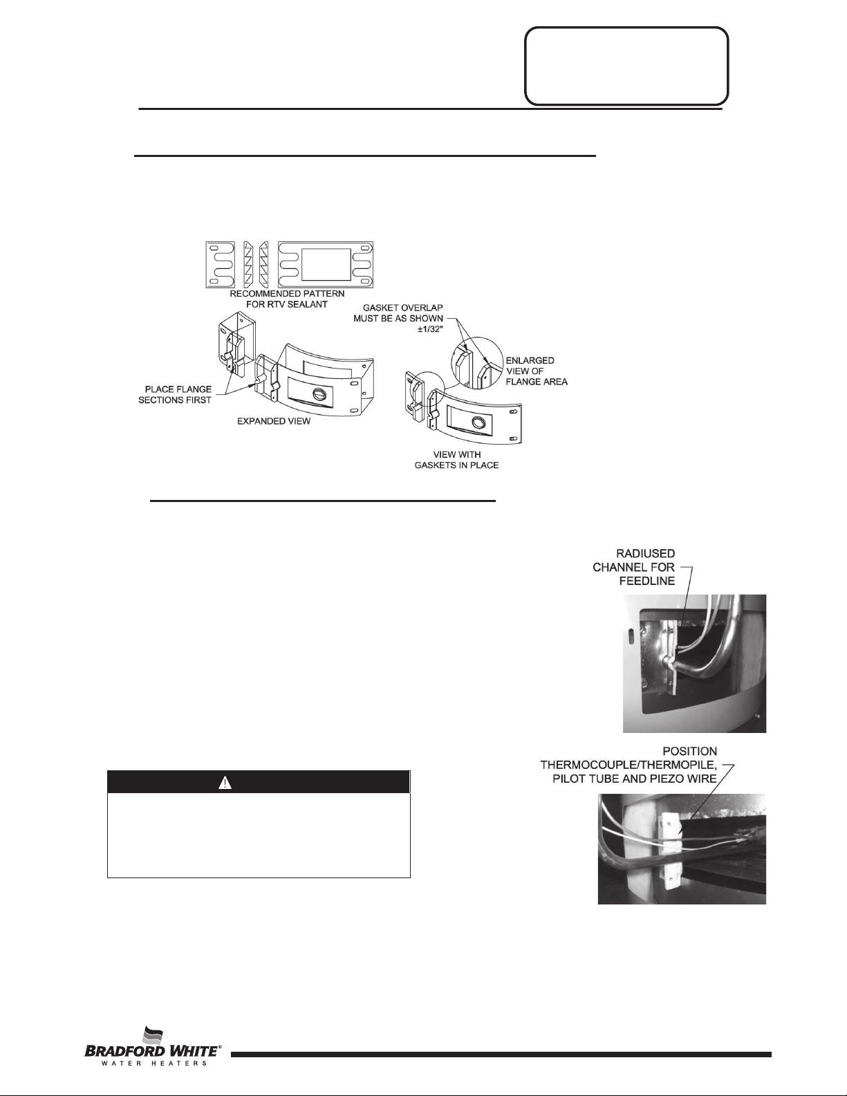
Step 2. Use RTV sealant (recommended bead size 1/8”) to secure the inner door gasket to the
inner door sections (right & left). Refer to the illustrations on the next page for proper
application. Note the overlap configuration in the flange area of the inner door. Set the
flange section first, this will help to achieve the proper overlap position.
Installation of Inner Door with Gasket
Step 1. Clean any residual gasket residue or other debris from combustion
chamber surface before installing the inner door/gasket assembly.
Step 2. Place the left side inner door and burner
assembly into position first. Using the three (3)
1/4” hex drive screws from Step 6 of “Inner Door
Removal Procedure,” secure left side inner door
in place. DO NOT OVER TIGHTEN SCREWS
Step 3. Position pilot tube and igniter/sensor wire against
left side inner door flange gasket.
Step 4. Firmly place right side inner door flange against
the left side inner door flange and secure with
two (2) 1/4” hex drive screws from Step 5 of
“Inner Door Removal Procedure”. DO NOT
OVER TIGHTEN SCREWS.
seal breach of inner door. A seal breach may
result in a fire or explosion causing property
damage, personal injury or death. DO NOT
13
13
Page 14
Service Procedure I
Inner Door Removal and
Replacement
DV Series
Installation of Inner Door with Gasket (cont.)
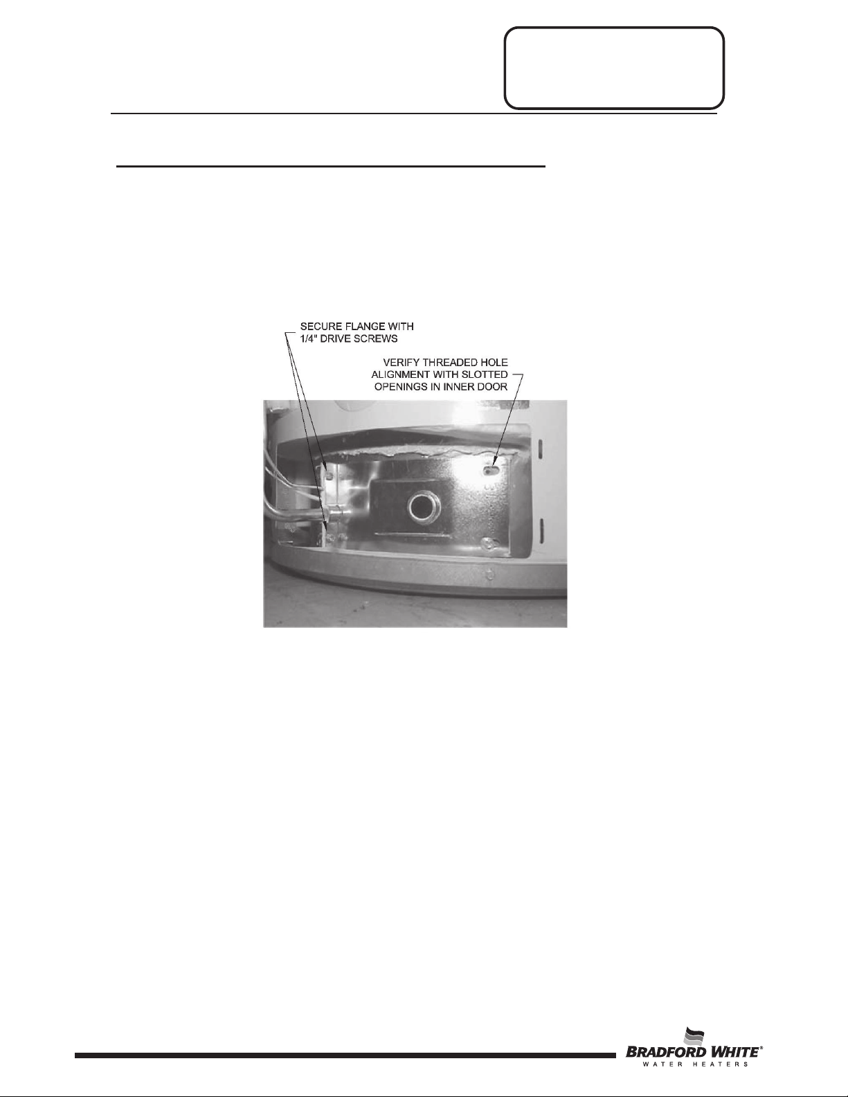
Step 5. Align right side inner door to combustion chamber and verify the fastener holes of
the combustion chamber are aligned with right side inner door slotted opening.
Verify seal integrity around combustion opening. Secure right side inner door using
1/4” hex drive screws from Step 4 of “Inner Door Removal Procedure”. DO NOT
OVER TIGHTEN SCREWS. Verify both left and right sides of inner door are
properly positioned and sealed against the combustion chamber.
Step 6. Replace outer jacket burner access door.
Step 7. To resume operation follow the instructions located on the lighting instruction label or
the lighting instructions located in the installation and operation manual.
14
14
Page 15

Service Procedure II
Thermocouple/Thermopile
Testing and Replacement
DV Series
Closed Circuit Thermocouple Testing (White Rodgers Mechanical)
Step 1. Closed circuit testing is the preferred method for testing the thermocouple. Following the
lighting instruction label on the heater, proceed to light the pilot and allow to operate for
three minutes. If the pilot will not stay lit, hold the pilot button (located on the combination
thermostat/gas valve) down during this test.
Step 2. Using a multimeter capable of measuring millivolts, connect one lead using an alligator clip
to the copper sheath of the thermocouple. Use the second lead of the multimeter to probe
the top terminal located at the back of the combination thermostat/gas valve.
Step 3. If meter reads 10 millivolts or higher, the thermocouple is O.K.. If reading is below 10
millivolts, replace the thermocouple.
Alligator clip to copper
sheath of thermocouple
Open Circuit Thermocouple Testing (White Rodgers Mechanical)
Step 1. Disconnect the thermocouple from the combination
thermostat/gas valve.
Step 2. Using a multimeter capable of measuring millivolts,
connect one alligator clip to the end ball or contact
portion of the thermocouple and the other alligator
clip to copper portion of the thermocouple.
Step 3. Following the lighting instruction label on the
heater, proceed to light the pilot and allow to
operate for three minutes. It will be necessary to
hold the pilot button down continuously
throughout this test. A reading of 20 to 30
millivolts indicates good thermocouple output.
15
15
Page 16

Service Procedure II
Thermocouple/Thermopile
Testing and Replacement
DV Series
Thermocouple Replacement (White Rodgers Mechanical)
Step 1. Turn off gas supply to the water heater. Rotate the knob of the combination
thermostat/gas valve to “OFF” position.
Step 2. Remove the outer jacket door.
Step 3. Remove the right side of the inner door per Service Procedure I, Steps 3a through
3c.
Step 4. Disconnect the thermocouple from the combination thermostat/gas valve. Locate
other end of the thermocouple inside of the combustion chamber and remove from
the pilot bracket. Pull firmly, pulling away from the pilot assembly.
Step 5. Install a new thermocouple into the pilot bracket, making certain the thermocouple is
fully engaged into the pilot bracket. Position the thermocouple against the left side
inner door flange at its original position. Connect the other end of thermocouple to
the combination thermostat/gas valve (finger tight + a 1/4 turn).
Step 6. Inspect the inner door gasket per Service Procedure I, Step 4.
Step 7. Install right side inner door per Service Procedure I, “Installation of Inner Door with
Gasket,” Step 6 through 8.
Step 8. To resume operation, follow the instructions located on the lighting instruction label
or the lighting instructions located in the Installation and Operation Manual.
16
16
Page 17

Service Procedure II
Thermocouple/Service
Testing and Replacement
DV Series
Closed Circuit Thermopile Testing
(White Rodgers Electronic and Honeywell)
Closed circuit thermopile testing is the preferred method for testing the thermopile.
Step 1. Following the lighting instruction label on the
heater, proceed to light the pilot and allow to
operate for three minutes. If the pilot will not
stay lit, hold the pilot button (rotate the gas
control knob to the pilot position, push and
hold in) during this test.
Step 2. Using a multimeter capable of measuring
millivolts, place one lead of the multimeter on
the left side of the wire harness and place the
second lead of the multimeter on the right side
of the wire harness.
Step 3. If meter reads 300 millivolts or higher, the
thermopile is O.K.. If reading is below 300
millivolts, replace the pilot assembly per
Service Procedure VI.
Open Circuit Thermopile Testing
(White Rodgers Electronic and Honeywell)
Step 1. Disconnect the red and white pilot wires from the gas control.
Step 2. Using a multimeter capable of measuring millivolts, connect one lead to the red
thermopile wire and one lead to the white thermopile wire.
Step 3. Following the lighting instruction label on
the heater, proceed to light the pilot and
allow the heater to operate for three
minutes. It will be necessary to hold
the gas control knob down in the
“PILOT” position continuously
throughout this test. A reading over
400 millivolts indicates a good thermopile
output.
Step 4. A reading under 400 millivolts indicates a
bad thermopile; replace the pilot
assembly per Service Procedure VI.
17
17
Page 18

Jumper
wire
head screwdriver
Service Procedure III
Igniter, Electrode Testing,
and Replacement
DV Series
Igniter, Electrode Testing and Replacement
Step 1. Remove the outer jacket door.
Step 2. Repeatedly depress the igniter button while viewing the pilot through the flame viewing
window. If a spark is present, the circuit is O.K.. If there is no spark, proceed to Step 3.
Step 3. Remove the white (or orange) wire from the gas control’s igniter wire. Hold the igniter
lead from the gas control to an unpainted surface such as the feedline and depress the
igniter. If there is a spark, the igniter is O.K.. Otherwise, the igniter is not functioning and
the pilot assembly must be replaced. See Service Procedure VI.
Step 4a. For White Rodgers Mechanical: to replace the igniter, disconnect the white (orange)
wire from the igniter. Use a flat-head screwdriver under the igniter and gently pry
bracket from the front of the gas calce and unhook the bracket from rear of the gas
valve.
Flat-
Step 4b. For Honeywell: to replace the igniter, see the Honeywell ONLY information in Service
18
Procedure IV.
18
Page 19

DV Series
ECO (Energy Cut Out) Testing
The Honeywell and White Rodgers Electronic gas
Operation Manual.
Line Pressure
Service Procedure IV
White Rodgers
Mechanical
Gas Control Testing and
Replacement
The gas control is designed for a maximum line pressure of 14.0” W.C.
and a minimum line pressure of the water heater’s rated manifold
pressure plus 1.0” W.C. (check rating plate). Line pressure must be
checked with the main burner on AND off to assure proper readings.
Manifold Pressure Testing
(This procedure presumes a maximum
line pressure of 14.0” W.C.)
Step 1. Position the gas control knob in the “OFF” position.
Step 2. Remove the pressure tap plug (3/16” allen wrench) and
install a 1/8” NPT pipe, coupling, and pressure tap.
Step 3. Connect a manometer to the pressure tap.
Step 4. Follow instructions located on the lighting
instruction label and proceed to light the main
burner. Observe the manometer readings.
Step 5. Proper operating range for natural gas is 4.0”
±0.5” W.C.; L.P. is 10.0” ±0.5” W.C..
a. If pressure is within the range specified in
the previous step, set the gas control knob to
the “OFF” position, remove manometer and
pressure tap, and replace pressure tap plug.
b. If the gas pressure is outside of the
specification noted above, refer to the
following Honeywell ONLY instructions or
“Gas Control Removal from Water Heater.”
Step 6. The manifold pressure is NOT adjustable. If
manifold pressure is outside of the range in
Step 5, the control must be replaced.
control is designed with an ECO device that will reset.
To reset the gas control after a status code 4, turn the
gas control knob to the “OFF” position and wait a
minimum of five (5) minutes before relighting, following
the instructions located on the lighting instruction label
or the lighting instructions located in the Installation and
19
19
Page 20

Alligator clip to copper
Service Procedure IV
Gas Control Testing and
Replacement
DV Series
Gas Valve Testing and Replacement (White Rodgers Mechanical)
The gas valve on the White Rodgers Mechanical is a non-repairable device. If troubleshooting has
determined a problem with the gas valve, it must be replaced.
If the burner and/or pilot do not fuction, service checks for gas pressure, thermocouple output,
magnet assembly, and ECO are to be performed. If these check O.K., the gas valve may be faulty.
Magnet Assembly Testing (White Rodgers Mechanical)
Step 1. Following the lighting instruction label on the heater, proceed to light the pilot and allow to
operate for three minutes. If the pilot will not stay lit, hold the pilot button (located on gas
valve) down during this test.
Step 2. Using a multimeter capable of measuring millivolts, connect one lead using an alligator clip
to the copper sheath of the thermocouple. Use the second lead of the multimeter to probe
the top terminal located at the back of the gas valve.
Step 3. With a meter reading of 13 millivolts or greater, rotate the knob of the combination
thermostat/gas valve to the “OFF” position.
Step 4. The magnet should remain closed for a drop of at least 6 millivolts. You will hear a “snap”
or “click” sound when the magnet opens; if you hear this sound prior to a drop of 6
millivolts, the magnet is out of specification and the gas valve should be replaced.
Energy Cut Off (ECO) Testing
Step 1. Disconnect the thermocouple from the gas valve.
Step 2. Using a multimeter capable of measuring ohms (or
continuity), attach one lead using an alligator clip to the
pilot tube. Insert the other lead fully into the magnet
opening. Be sure the lead makes contact only at the top
center of the magnet opening. DO NOT allow the lead to
make contact with the threaded sides of the opening.
Step 3. If continuity is indicated, the ECO is O.K.. If continuity is not
indicated, the ECO has opened, and the gas valve must be replaced.
sheath of thermocouple
20
20
Page 21

DV Series
For White Rodgers Control,
.
To remove or
install control,
insert only 1/2”
threaded
pipe into inlet and
use to loosen or
tighten control
Service Procedure IV
Gas Control Testing and
Replacement
Combination Thermostat/Gas Valve Replacement
(White Rodgers Mechanical)
Step 1. Rotate the knob of the gas valve to the “OFF” position.
Step 2. Turn off gas supply to the water heater.
Step 3. Disconnect the gas supply line from the gas valve.
Step 4. Turn off the water supply and drain the water heater
completely.
Step 5. Remove the outer jacket burner access door.
Step 6: Right side inner door removal:
a. Disconnect resettable thermal switch wire leads (leading from gas valve) and remove the
wire tie from the feedline.
b. Remove two (2) 1/4” hex drive screws from the right side inner door.
c. Remove two (2) 1/4” hex drive screws from the flange section of the inner door.
d. Remove the right side inner door and set aside. Be careful to not damage the gasket
material on the inner door.
NPT
depress knob slightly and rotate
clockwise to the “OFF” position
Step 7. Removal of gas valve:
a. Disconnect the main burner feedline, pilot tube, and thermocouple from the gas valve.
b. Remove piezo bracket with piezo igniter (refer to Service Procedure IV) from gas valve.
c. Remove gas valve from the water heater, rotating counter clockwise using a control body
Remove the burner from the combustion chamber.
Note: Feedline nut for natural gas control uses right hand threads; L.P. control uses left
hand thread.
wrench or a length of 1/2” NPT pipe threaded into the inlet of the control.
21
21
Page 22

● Gasket adhesion to inner door
seal
● Material left on combustion chamber
WARNING
A seal breach may result in a
injury or death.
Service Procedure IV
Gas Control Testing and
Replacement
DV Series
Combination Thermostat/Gas Valve Replacement (cont.)
(White Rodgers Mechanical)
Step 8. Installation of gas valve:
a. Install new gas valve using a control body wrench or a length of 1/2" NPT pipe threaded
into inlet of control. DO NOT OVER TIGHTEN. Use caution not to damage cast
aluminum body of gas valve. Be certain not to damage the bundled wire leads.
NOTE: Gas valve must be installed in proper upright position to assure the
feedline will align properly at the inner door flange. DO NOT OVER TIGHTEN.
b. Reattach piezo bracket with piezo igniter to gas valve.
c. Reattach main burner feedline, pilot tube and thermocouple to gas valve.
NOTE: Feedline nut for natural gas control uses right hand threads;
d) Gather wire leads of gas valve and piezo igniter and secure alongside of feedline using
new wire tie provided.
e) Connect gas supply piping to inlet of control. Use back up wrench on wrench boss of
control, NEVER use back up wrench on body of control.
Step 9: Reinstallation of inner door assembly:
a. Prior to reinstallation of inner door, fully inspect inner door gasket for the following:
If the gasket is not affected by any of the above, gasket replacement will not be required.
If replacement is required, replace using new gasket kit following the provided instructions.
b. Clean any gasket residue or other debris from combustion chamber surface before installing the
inner door/gasket assembly.
If control is turned past proper alignment, DO NOT reverse direction to align.
L.P. control uses left hand thread.
● Tears
● Missing material
● Other imperfections that will inhibit proper
● Cracks
● Dirt or debris
fire or explosion causing
property damage, personal
22
22
Page 23

Service Procedure IV
Gas Control Testing and
DV Series
Replacement
Combination Thermostat/Gas Valve Replacement (cont.)
c. Position thermocouple, pilot tube and piezo wire against left side inner door flange gasket.
DO NOT
thermocouple and pilot tube are not in position to interfere with outer jacket burner access
door when reinstalled.
d. Firmly place the right side inner door flange against the left side inner door flange and
secure with two (2) hex drive screws from Step 6c. DO NOT OVER TIGHTEN SCREWS.
e. Align the right side inner door to combustion chamber and verify the fastener holes of the
combustion chamber are aligned with the right-side inner door slotted openings. Verify seal
integrity around the combustion opening. Secure right-side inner door using two (2) hex drive
screws from Step 6b. DO NOT OVER TIGHTEN SCREWS. Verify both left and right sides
of the inner door are properly positioned and sealed against the combustion chamber.
Step 10. Reconnect wire leads from the gas valve to resettable thermal switch (see Step 6 photo).
NOTE: Wire terminations are interchangeable with either resettable thermal switch connection.
Step 11. Replace the outer jacket burner acess door.
ROUTE THROUGH RADIUSED CHANNEL WITH FEEDLINE. Be sure that
Step 12. Reconnect the gas supply to the gas valve.
Step 13. Resume water supply to the water heater. Be sure the tank is full of water.
Step 14. To resume operation, follow the instructions located on the lighting instruction label or
the lighting instructions located in the Installation and Operation Manual.
23
23
Page 24

DV Series
CAUTION
Use caution to not bend or
the gas control cover.
NOTE: The following procedure applies to the Honeywell gas controls ONLY.
Rotate knob counter-clockwise
cover screw
Service Procedure IV
Gas control
screws
Replacement (Honeywell ONLY)
Honeywell Cover Removal
Step 1. Rotate the knob of the gas control to the “OFF”
position.
Step 2. Turn off gas supply to the water heater.
Step 3. Disconnect the gas supply line from the gas control.
Step 4. Disconnect the igniter wire.
Step 5. For Honeywell V1, remove the gas control cover
screw using a flat-head screwdriver.
Gas Control Testing and
damage valve body pins
when removing or installing
to the “OFF” position
Gas control
a. For Honeywell V2, remove (4) gas control cover screws using a flat-head screwdriver.
24
24
Page 25

Valve body
Service Procedure IV
Gas Control Testing and
DV Series
Replacement (Honeywell ONLY)
Honeywell Cover Removal (cont.)
Step 6. Depress both tabs on the top of the gas control cover (Honeywell V1 only) and pull
straight out to remove.
Step 7. Disconnect the temperature sensor from the control board and remove the wire from
the temperature sensor wire routing clip (image on next page).
pins
25
25
Page 26

DV Series
Release lock tab
Temperature sensor
Disconnect
Service Procedure IV
Honeywell Cover Removal (cont.)
Gas Control Testing and
Replacement (Honeywell ONLY)
wire routing clip
temperature sensor
Step 8. Remove the piezo igniter from the control cover by releasing the lock tab on the
control cover
26
26
Page 27

Honeywell Valve Body Removal and Temperature Sensor Removal
side second
Valve body screw
CAUTION
Use caution to not
valve body pins.
CAUTION
When reinstalling
sensor wires.
wire routing clips
inserted into backplate
Service Procedure IV
Gas Control Testing and
DV Series
Replacement (Honeywell ONLY)
Step 1. Disconnect the burner and pilot tubes per Service Procedure II.
Step 2. Remove the valve body by removing the screw located at the lower
left corner. Unclip the lower right side from the backplate first,
followed by the lower left side, using a flat-head screwdriver.
bend or damage
Unclip lower left
Unclip lower right
side first
Step 3. Remove the temperature sensor and insertion stick from the backplate by first removing
the wire from the temperature sensor wire routing clips. Make note of the insertion stick’s
orientation, as the insertion stick can only be installed in one way.
Temperature sensor
temperature sensor and
insertion stick, make sure
the assembly is inserted
FULLY into the backplate
and the wires are routed
through the wire routing
clips. Failure to do so will
not allow the valve body to
be reinstalled properly and
may damage temperature
Insertion stick fully
27
27
Page 28

Pull in this direction
Temperature
Insertion
Pull
Service Procedure IV
Gas Control Testing and
Replacement (Honeywell ONLY)
DV Series
Honeywell Valve Body Removal and Temperature Sensor Removal (cont.)
Step 4. Remove the temperature sensor from the insertion stick by pulling it apart as illustrated
below.
Step 5. To reassemble the gas control, follow the previous steps in reverse order. Once the gas
control is reassembled, the burner assembly is reinstalled, and the gas supply line is
reconnected, resume water supply to the water heater. Be sure the tank is full of water
before relighting.
Step 6. To resume operation, follow the instructions located on the lighting instruction label, or
the lighting instructions located in the Installation and Operation Manual.
in this direction
stick
sensor
28
28
Page 29

DV Series
NOTE: Using a multi-meter set to the
CAUTION
DO NOT use standard
inserted into connector.
Service Procedure IV
Temperature Sensor Testing (Honeywell)
Gas Control Testing and
Replacement (Honeywell ONLY)
Step 1. If control has gone into lockout due to excessive
tank temperature (four flashes, three second
pause), reset control by rotating gas control knob
to “OFF” position and wait a minimum of five (5)
minutes. Then follow lighting instructions and
return the gas control knob to a desired setpoint.
Step 2. Observe green light indicator. Does status code 4
(four flashes, three second pause) appear?
a. If no, resume normal operation.
b. If yes, continue with Step 3.
Step 3. Following “Honeywell Cover Removal,”
“Honeywell Valve Body Removal and
Temperature Sensor Removal” instructions,
disassemble gas control to access the
temperature sensor.
Step 4. With the temperature sensor still in the back
plate, use a multimeter set to the ohms setting,
determine the resistance of the temperature
sensor (see photo).
multimeter probes for this test.
Doing so will damage
connector. Use special pin
type electronic probes or
small diameter wire pins
ohms setting, insert one-meter probe
into center wire position of thermal
well connector, insert the second
probe into either of the outside wire
positions (see photo).
Alternate the probe on the outside
position to the opposite outside wire
position (see photo).
Step 5. See next page to obtain water temperature. Are temperature sensor values correct?
a. If no, replace the temperature sensor.
b. If yes, replace the gas control.
29
29
Page 30

NOTE:
It is important to understand once the resistance for the temperature sensor is determined from the
tank affecting the resistance value of the temperature sensor.
In Degrees F
°F 0 1 2 3 4 5 6 7 8 9
40
26109
25400
24712
24045
23399
22771
22163
21573
21000
20445
50
19906
19383
18876
18383
17905
17440
16990
16553
16128
15715
60
15314
14925
14548
14180
13823
13477
13140
12812
12494
12185
70
11884
11592
11308
11032
10763
10502
10248
10000
9760
9526
80
9299
9078
8862
8653
8449
8250
8057
7869
7685
7507
90
7333
7165
7000
6839
6683
6531
6383
6238
6098
5961
100
5827
5697
5570
5446
5326
5208
5094
4982
4873
4767
110
4663
4562
4464
4368
4274
4183
4094
4006
3922
3839
120
3758
3679
3602
3527
3453
3382
3312
3244
3177
3112
130
3048
2986
2925
2866
2808
2752
2697
2643
2590
2538
140
2488
2439
2391
2344
2298
2253
2209
2166
2124
2083
150
2043
2004
1966
1928
1891
1856
1820
1786
1753
1720
160
1688
1656
1625
1595
1566
1537
1509
1481
1454
1427
170
1402
1376
1351
1327
1303
1280
1257
1235
1213
1191
180
1170
1150
1129
1110
1090
1071
1053
1035
1017
999
190
982
965
949
933
917
901
886
871
857
842
200
828
814
801
788
775
762
749
737
725
713
Service Procedure IV
Gas Control Testing and
Replacement
DV Series
Determine Water Temperature Inside Tank
previous page, water flow through the water heater should not occur. Prior to drawing water from
drain valve, turn off the cold-water supply to the water heater. This will prevent cold water flow into the
Step 1. Position the gas control knob to the “OFF” position.
Step 2. Draw approximately 4 gallons of water from the drain valve into a container and discard.
Draw an additional gallon and immediately measure water temperature using an accurate
thermometer. It may be necessary to open a hot water faucet to allow water heater to drain.
Step 3. Using the chart below, determine the correct resistance value for the water temperature
from Step 2. Example: If water temperature is 84 F, then the resistance through the sensor
would be 8449.
Note: Sensor resistance increases as the temperature decreases
Sensor Resistance at Various Temperature
30
30
Page 31

DV Series
Service Procedure IV
Gas Control Testing and
Replacement
Gas Control Replacement (White Rodgers Electronic and Honeywell)
Step 1. Rotate the gas control knob to the “OFF” position.
Step 2. Turn off gas supply to the water heater.
Step 3. Disconnect the gas supply line from the gas control.
Step 4. Turn off the water supply and drain the water heater completely.
Step 5. Remove the outer jacket burner access door.
Step 6. Right side inner door removal:
a. Disconnect the red wire leads from the resettable
thermal switch.
b. Remove two (2) 1/4” hex drive screws from right side
inner door.
c. Remove two (2) 1/4” hex drive screws from flange
section of inner door.
d. Remove the right side inner door and set aside. Be
careful to not damage gasket material on the inner
door.
Step 7. Removal of gas control:
a. Disconnect the main burner feedline, pilot tube, igniter wire, innder door wire (red), and
thermopile wire (white) from the gas control.
b. Remove gas control from water heater by rotating counter clockwise. DO NOT use a
wrench on the gas control body, as damage to the gas control may occur. If necessary,
use a length of 1/2” NPT pipe threaded into gas inlet of gas control.
Step 8. Install new gas control into water heater:
a. Install a new gas control into water heater by rotating clockwise. DO NOT use a wrench on
the gas control body, as damage to the gas control may occur. If necessary, use a length of
1/2” NPT pipe threaded into gas inlet of gas control.
31
31
Page 32

● Gasket adhesion to inner door
● Other imperfections that will inhibit proper seal
CAUTION
Use back up wrench on wrench boss of gas control, NEVER use back up wrench on body of gas control.
WARNING
A seal breach may result in a fire or
personal injury or death.
Service Procedure IV
Gas Control Testing and
Replacement
DV Series
Gas Control Replacement (cont.)
b. Reattach the main burner feedline, pilot tube, igniter wire, inner door wire (red), and
thermopile wire (white) to the gas control. Attach the inner door wire (red) to the positive (+)
terminal and the thermopile wire (white) to the negative (-) terminal.
c. Gather igniter wire, thermopile wire (white), inner door wire (red), and pilot alongside of
feedline using new wire tie provided.
d. Reconnect gas supply piping to inlet of gas control.
Step 9. Reinstallation of inner door assembly:
a. Prior to reinstallation of inner door, fully inspect inner door gasket for the following:
● Tears
● Missing material
● Cracks
● Dirt or debris
If the gasket is not affected by any of the above, gasket replacement will not be required. If
replacement is required, replace using a new gasket kit following the instructions provided with the kit.
b. Cleanany gasket residue or other debris from the combustion chamber surface before
installing the inner door/gasket assembly.
c. Position the thermopile wire, pilot tube, and igniter wire against left side inner door flange
gasket. DO NOT ROUTE THROUGH RADIUSED CHANNEL WITH FEEDLINE. Be sure
that the thermopile and pilot tube are not in position to interfere with the outer jacket burner
access door when reinstalled.
explosion causing property damage,
● Material left on combustion chamber
32
32
Page 33

DV Series
CAUTION
Use back up wrench on
on body of gas control.
Service Procedure IV
Gas Control Replacement (cont.)
d. Firmly place right side inner door flange against the left side inner door flange and
secure with two (2) 1/4” hex drive screws from Step 6c. DO NOT OVER TIGHTEN
SCREWS.
e. Align the right side inner door to combustion chamber and verify the fastener holes of
the combustion chamber are aligned with the right side inner door slotted openings.
Verify seal integrity around the combustion opening. Secure right side inner door
using two (2) 1/4” hex drive screws from Step 6b. DO NOT OVER TIGHTEN
SCREWS. Verify both left and right sides of the inner door are properly positioned
and sealed against the combustion chamber.
wrench boss of gas control,
NEVER use back up wrench
Gas Control Testing and
Replacement
Step 10. Reconnect two (2) red wire leads from pilot assembly and gas control to resettable
thermal switch.
NOTE: Wire terminations are interchangeable with either resettable
thermal switch connection.
Step 11. Replace the outer jacket burner access door.
Step 12. Reconnect the gas supply to the gas control.
Step 13. Resume water supply to the water heater. Be sure the tank is full of water before
resuming operation.
Step 14. To resume operation, follow the instructions located on the lighting instruction label
or the lighting instructions located in the Installation and Operation Manual.
33
33
Page 34

NOTICE
Feedline nut for natural gas control
uses left hand threads.
Service Procedure V
Burner Operation Inspection,
Cleaning, and Replacement
DV Series
Burner Inspection
At periodic intervals (every 6 months) a visual inspection should be made of the pilot and main
burner for proper operation and to assure no debris is accumulating.
Pilot flame should be stable, some causes for an unstable pilot flame are:
x Water heater vent is less than the allowable vent length.
x Gas pressure is out of specification.
x Pilot flame not fully engulfing spark/flame sensor.
Main burner should light smoothly from pilot and
burn with a blue flame with a minimum of yellow
tips.
Main burner must be free from any debris
accumulation that may affect burner operation
(see burner cleaning procedure below).
Burner Removal
Step 1. Position the gas control knob in the
“OFF” position.
Step 2. Turn off the gas supply to the water
heater.
Step 3. Remove the outer jacket door.
Remove the inner doors per Service
Procedure I.
Step 4. Disconnect the igniter wire from the
gas control.
Step 5. Disconnect the red and white pilot
wires from the gas control.
Step 6. Disconnect the pilot feedline (7/16”
wrench) from the gas control.
Step 7. Disconnect the main burner feedline
(3/4” wrench) from the gas control.
uses right hand threads; L.P. control
Step 8. Remove the burner assembly from the
combustion chamber.
34
34
Page 35

DV Series
Service Procedure V
Burner Cleaning
Step 1. Follow the steps in “Burner
Removal” on page 33.
Step 2. Thoroughly inspect the burner
surface area and the burner port
area and remove any loose
debris.
Step 3. Disconnect burner plate from main burner
orifice and disconnect feedline from burner.
Burner Operation Inspection,
Cleaning, and Replacement
Step 4. Remove main burner orifice from feed line.
Inspect and clean if necessary.
Step 5. Inspect the orifice; clean or replace if
necessary.
Step 6. Reassemble the burner and reinstall into
the water heater.
Step 7. Restore the gas supply and check for
any gas leaks.
Step 8. To resume operation, follow the
instructions located on the lighting
instruction label or the lighting
instructions located in the Installation
and Operation Manual.
35
35
Page 36

DV Series
Service Procedure VI
Honeywell Pilot
Note: Steps 6 through 11 are for Honeywell ONLY.
Pilot Inspection, Testing, and Replacement
Step 1. Remove burner following the steps listed in
“Burner Removal” on page 33.
Step 2. Remove the pilot assembly from the feedline
(1/4” nut driver).
Step 3. Visually inspect the igniter wire for damage.
Replace pilot if damaged. Electrode should
not be in contact with the pilot hood.
Step 4. With a multi-meter set to ohms setting,
check continuity through igniter wire.
Replace pilot if there is no continuity.
Step 5. Visually inspect igniter electrode for
oxidation build up. Carefully clean any
oxidation using a very fine emery cloth.
Pilot Testing, Cleaning,
and Replacement
Step 6. Visually inspect the pilot tubing for kinks or cracks. If damage is found, replace
the pilot assembly.
Step 7. Inspect the pilot tubing and the pilot orifice for blockage:
a. Remove the ferrule nut from the bottom of the pilot assembly (7/16” wrench).
b. Remove the pilot tube and pilot orifice.
c. Inspect the pilot tubing and orifice for blockage. Clean or replace as necessary.
Step 8. Reassemble the pilot and install onto the burner.
Step 9. Reinstall the burner assembly into the water heater.
Step 10. Restore the gas supply and check for any gas leaks.
Step 11. To resume operation, follow the instructions located on the lighting instruction
label or the lighting instructions located in the Installation and Operation
Manual.
36
36
Page 37

DV Series
Service Procedure VII
1.
Verify adequate combustion air
deposits and debris.
Resettable thermal switch color
code reference
Approximate
(open)
Blue
240˚
Yellow
270˚
Red
290˚
Resettable Thermal Switch Continuity Testing
Step 1. Remove the outer jacket door.
Step 2. Disconnect the wire leads from the resettable thermal
switch.
Step 3. Using a multimeter capable of measuring continuity
(ohms), place one probe of the meter on one of the
brass connection tabs of the resettable thermal switch,
and the remaining probe on the other connection tab.
Resettable Thermal Switch
Testing and Replacement
Step 4. If continuity is indicated, the switch is closed, allowing millivolt current to pass.
Step 5. If continuity is not indicated, the switch is open, possibly due to an overheating
condition. The switch is designed to open at a predetermined temperatures
depending on the model. An open switch can be reset by depressing the red colored
button located at the center of the switch. The overheating condition must be
determined prior to putting the heater back in service.
PROBABLE CAUSE FOR RESETTABLE THERMAL SWITCH ACTIVATION
PROBABLE CAUSE SERVICE PROCEDURE
supply is available.
Insufficient combustion air
1.
Weak switch or switch out
of calibration.
2.
Incorrect switch.
2.
Clear jacket slot openings of any
dirt, dust, restrictions or other
3.
Inspect flame arrestor plate and
clean with a
compressed air to remove scale
1.
Replace resettable thermal switch.
2.
Verify switch color code and
approximate
obstructions.
stiff brush,
temperature.
Color code
switch
activation
temperature
Flammable vapor incident 1. Replace water heater.
37
37
Page 38

Service Procedure VII
Resettable Thermal Switch
Testing and Replacement
DV Series
Resettable Thermal Switch Replacement
Step 1. Rotate the knob of combination thermostat/gas valve to the “OFF” position.
Step 2. Remove the outer jacket door.
Step 3. Disconnect the wire leads from the resettable
thermal switch.
Step 4. Remove the resettable thermal switch from the
inner door (Phillips screwdriver).
Step 5. Put new resettable thermal switch in place. Be sure
contact surface of resettable thermal switch and inner
door are free of any debris. Secure resettable thermal
switch into place using screws from Step 4. DO NOT
OVER TIGHTEN SCREWS.
Step 6. Reconnect wire leads from combination
thermostat/gas valve to resettable thermal switch.
NOTE: Wire terminations are interchangeable with
either resettable thermal switch connection.
Step 7. Replace the outer jacket door.
Step 8. To resume operation, follow the instructions located on the lighting instruction label
or the lighting instruction located in the Installation and Operation Manual.
38
38
Page 39

WARNING
Water heater components and stored water may be HOT when
precaution to prevent personal injury.
Service Procedure VIII
Diptube Inspection and
DV Series
Replacement
Diptube Inspection and Replacement
performing the following steps in this procedure. Take necessary
Step 1. Position the gas control knob to the “OFF” position.
Step 2. Turn off the cold water supply to the water heater.
Step 3. Connect a hose to the drain valve of the water heater and route to an open drain.
Step 4. Open a nearby hot water faucet to vent the water heater for draining.
Step 5. Open the drain valve of the water heater and allow the heater to drain to a level
below the inlet connection nipple.
Step 6. Disconnect the inlet nipple from the plumbing system.
Step 7. With an appropriate tool, such as a pipe wrench, remove the inlet nipple/diptube from
the water heater. Use caution to not damage any pipe threads.
Step 8. Visually inspect the inlet nipple/diptube. The inlet nipple/diptube should be free of
cracks and any blockage. Hydrojet slots should be open and free of any blockage.
Any damage such as cracks, restriction due to deformation, or unintentional holes are
NOT field repairable and the inlet nipple/diptube must be replaced.
Step 9. Upon completion of inspection or subsequent replacement, re-install the inlet
nipple/diptube into the water heater. Ensure pipe dope is used on the nipple’s
threads. Connect the nipple/diptube to the plumbing system and resume the water
supply to refill the heater with water.
Step 10. To resume operation, follow the instructions located on the lighting instruction label or
the lighting instructions located in the Installation and Operation Manual.
39
39
Page 40

DV Series
WARNING
Water heater components and stored water may be HOT when
precaution to prevent personal injury.
Service Procedure IX
Anode Inspection and Replacement
Anode Inspection and
Replacement
Step 1. Position the gas control knob to the “OFF” position.
Step 2. Turn off the cold water supply to the water heater.
Step 3. Connect a hose to the drain valve of the water heater and route it to an open drain.
Step 4. Open a nearby hot water faucet to vent the water heater for draining.
Step 5. Open the drain valve of the water heater and allow the water heater to drain to a
Step 6. Disconnect the outlet nipple from the plumbing system.
Step 7. With an appropriate tool, such as a pipe wrench, remove the outlet nipple/anode
Step 8. Visually inspect the outlet nipple/anode. The outlet nipple/anode should show signs
Step 9. Upon completion of inspection or subsequent replacement, re-install the inlet
performing the following steps in this procedure. Take necessary
point below the outlet connection nipple.
from the water heater. Use caution to not damage the pipe threads.
of depletion; this is normal. If the depletion is 1/2 of the original anode diameter
(approximately 3/4” diameter), replacement is recommended. If any of the steel core
of the anode is exposed, replacement is recommended.
nipple/diptube into the water heater. Ensure pipe dope is used on the nipple’s
threads. Connect the nipple/diptube to the plumbing system and resume the water
supply to refill with water.
Step 10. To resume operation, follow the instructions located on the lighting instruction label
or the lighting instructions located in the Installation and Operation Manual.
40
40
Page 41

DV Series
Glossary of Terms
BTU British thermal units
GPM Gallons per minute
Hz Hertz
KWh Kilowatt hour
LED Light emitting diode
NPT National pipe thread
Ohms Ohms of resistance
PSI Pounds per square inch
RPM Revolutions per minute
Glossary of Terms
ECO Energy cut out
VAC Volts alternating current
“W.C. Inches of water column
ºC Degrees centigrade
ºF Degrees fahrenheit
41
41
Page 42

DV Series
1.
Venting Package Complete
11.
Inlet Diptube
21.
Feedline Clip
2.
Venting Protection Screen
12.
T&P Valve
22.
Right Side Inner Door
3.
Plenum
13.
3/4 NPT plug (“H” Models only)
23.
Left Side Inner Door
4.
Plenum Gasket
14.
Air Intake Boot
24.
Outer Door
5.
Rear Air Intake Tube
15.
Air Intake Boot Gasket
25.
Brass Drain Valve
6.
Flue Reducer
16.
Burner Assy. Complete
26.
Gas Control
7.
Heat Trap Outlet
17.
Main Burner
27.
Inner Door Gasket Kit
8.
Anode Outlet Device
18.
Main Burner Orifice
28.
Kit-Heat Trap Insert
9.
Flue Baffle
19.
Pilot Assy.
29.
ASSE Approved Mixing Valve
10.
Heat Trap Inlet
20.
Feedline
Parts Diagram
42
42
Page 43

Page 44

 Loading...