

Bradford White EFT-15000-4-D-10, EFT-19000-4-D-10, EFT-20000-5-D-10, EFT-16000-5-D-10 Troubleshooting Manual
Page 1
TROUBLESHOOTING GUIDE
ELECTRIC INSTANTANEOUS TANKLESS WATER HEATER
All information necessary to troubleshoot this water
heating unit is contained in this fully illustrated
guide. If problems still exist after reading and
carrying out the instructions in this manual, contact
Technical Service at the toll free number
below for assistance.
PHONE TOLL FREE:
1-800-334-3393
SERIES TWO
“EFT” MODELS
EFT-15000-4-D-10 240V
EFT-19000-4-D-10 240V
EFT-16000-5-D-10 277V
EFT-20000-5-D-10 277V
238-43143-00 Rev. 5/02
Page 2
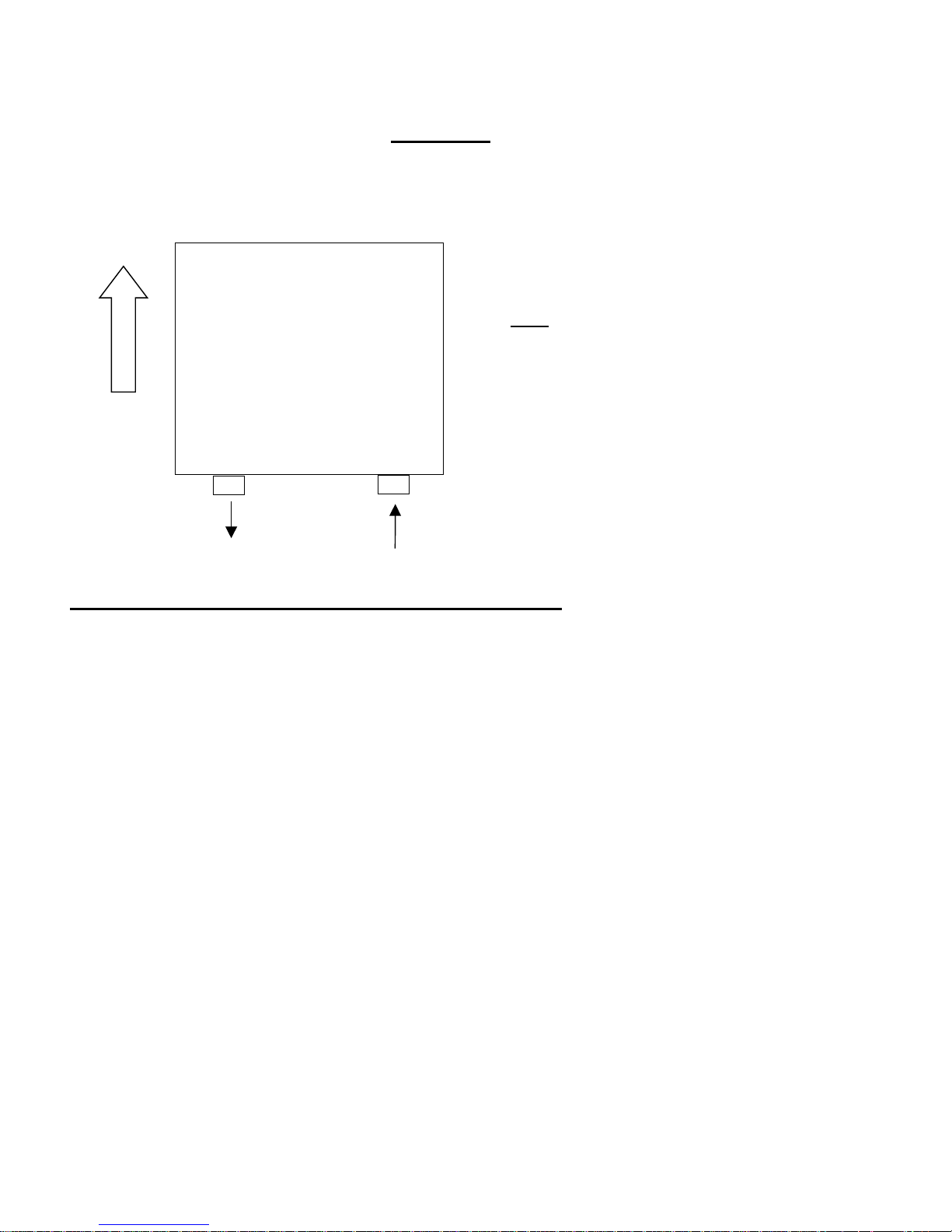
General
Before removing the front cover, make sure the unit is mounted correctly with the
water fittings at the bottom.
UP
Serial number
Water out
Water in
If there are no indicator lights illuminated, then:
If there are no indicator lights illuminated, measure the flow rate of water going through the unit.
activating flow rate” varies with each model. You must determine which “Series Two” model
The “
you have. Look at the rating label, find the
reference the required flow rate to activate the unit.
Measuring Flow Rate:
1) “EFT” requires at least 0.9 gallons per minute to switch on.
Fill a 1-gallon “milk” container and, using only water from the hot water outlet, record the time
(In seconds) required to fill. To calculate the flow rate, divide the number of gallons the
container holds (in this case one gallon) by the time required to fill.
e.g. If it takes 87 seconds to fill the container then the flow rate would be
Flow Rate (gpm)=v/t x 60 = 1 gal./87 seconds x 60 seconds/1 minute=.69 GPM
If there is insufficient water flow to activate the unit, then you must provide more water to the
system by
opening the valves fully.
If there is sufficient water flow and still no indicator lights, then proceed to the next step.
order ref. number and then (From the data) cross
When correctly mounted, this “ Series Two” water
heating unit should look like the diagram to the
ANY other mounting configuration will
left.
prevent the unit from operating properly.
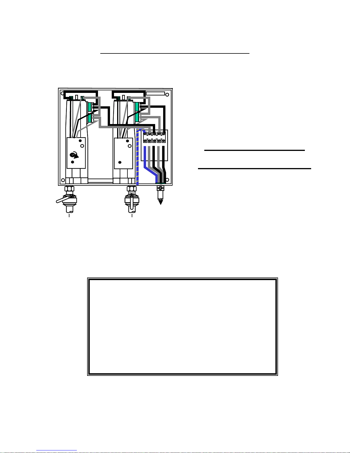
Remove the front cover and observe the
indicator light on the circuit board of each
module.
With the power switched
“ON” to the unit, run
water through the unit by opening several faucets
supplied by the unit. If any indicator lights
illuminate, note their position and if the
illumination is steady or pulsing.
2
Page 3

Danger: Disconnect all power to the water heater
“Series Two” water heating units are comprised of
purpose of troubleshooting, each of these two modules will be considered separately. Neither of
the two will have any effect on the performance of the other.
NOTE: Make sure power is “OFF” before proceeding.
For each module:
A multimeter/voltmeter is required to perform the
following test.
Set the meter to measure Ohms, Ω, on the
Single Ohm Scale (Not Rx1K or Rx1Meg).
Remove the front cover of the unit. At the end of the
gray heater body, there are two threaded silver rods with brass nuts on them (Where the wires
connect). Take a reading of the ohms value between these two rods and write it down (See figure
below).
If the reading is less then 20 ohms on the single
(Rx1) scale or the (Rx10) scale, then the element is
good, if it is
e.g. 10,000 Ohms or if you get a reading on the “Rx1k,
you will need to replace the element. To do this, contact
Technical Service at 1-800-334-3393 for replacement
elements (Please write down the resistance value,
before contacting Technical Service, this will be very
useful to us. Also have the order ref. number and serial
number for your unit available for Technical Service).
If indicator light illuminates or pulses, but water is not heated or the water
temperature is too low:
1) The water flow rate is too high. Reduce the water flow using the faucet. With experimentation,
you should notice an increase in temperature.
2) Make sure the unit is connected to the voltage supply specified on the U.L. rating label located
on the front cover of the unit.
3) Measure the resistance of the element as described above.
If these steps fail to get the water heater working properly
then follow the instructions on the next page.
two individual heating modules. For the
much greater.
3
Page 4

Make sure the PCB’s (Printed Circuit Boards) are correctly mounted:
BE SURE ELECTRICTY IS TURNED “OFF” BEFORE PROCEEDING.
Make sure the printed circuit board is mounted in the correct position. This is the top set of
mounting holes (See diagram below). Failure to mount the PCB in the correct position will cause
element burn out and may cause further damage to the unit (This board may have been
incorrectly positioned if serviced previously).
Note: The upper mounting position is
applicable to all modules regardless
of their type.
The correct mounting
holes for the PCB on
all “ES,EFC,or EFT ”
models.
Board mounted in correct
position
Inlet filter
Inspect the inlet filter
Inspect the inlet filter (See diagram above for location). Make sure the inlet filter screen is free
from debris, pipe dope or any other foreign materials that may prevent adequate water flow.
One or more lights illuminate:(or previous remedies failed)
4
Page 5

“Series Two” water heaters are comprised of two individual heating modules. For the purpose of
troubleshooting, each of these two modules will be considered as a separate unit. Neither having
any effect on the performance of the other. These modules fall in to
1) Thermostatically controlled modules 2) Flow controlled modules. (Non-thermostatic)
one of two categories:
Model Types / Order Ref Number:
Look at the order ref. number on the label located on the front cover of the unit. In the top
left hand box find the “Order Ref.” Find the order reference number on the list below to
confirm the type of heating modules you have.
Heater Model Number Module Types and Qty.
Order Ref Number: & UL Rating Label Thermostatic Flow Controlled
EFT-15000-4-D-10 1 1
EFT-19000-4-D-10 1 1
EFT-16000-5-D-10 1 1
EFT-20000-5-D-10 1 1
For “Thermostatic” modules only
If the indicator light on the circuit board flashes one time very quickly when
the water is switched on then:
Turn off all power to the water heating unit.
Warning
1) Turn “OFF” the power to this unit and all other units that may feed hot water to this unit,
including the right hand side module and any other preheating units.
2) Be sure that this module is fed with
cold water only during this test. This unit must not be fed
with pre-heated water when performing this test.
3) There are six thin leads connected to the printed circuit board. Disconnect the
third wire from
the left, from the top of the PCB (As indicated below) and tape off the end with insulating tape.
4) Run water from hot water faucet for 30 seconds and then switch power
“ON” to the unit once
more.
With the water flowing:
If the light illuminates steadily, contact Technical Service and request a replacement printed circuit
board (Part #EX100). If the light still does not illuminate contact Technical Service and consult
with a technician.
5
Page 6

Do not use this unit with any
pre-heated water feed if the light has
illuminated steadily, having performed
The unit in this state must
only be fed with cold water.
WARNING
the above test.
3rd wire from left
For “Non-Thermostatic” modules only
If the indicator light on the printed circuit board illuminates with the water flowing and there is no
heating of the water, it is highly likely that the heating element has been damaged. If the above
situation occurs, contact Technical Service for replacement elements.
IF HAVING CARRIED OUT ALL THE TESTS LISTED ABOVE AND THE WATER
HEATING UNIT IS STILL NOT FUNCTIONING, PLEASE CONTACT TECHNICAL
SERVICE AT 1-800-334-3393.
PLEASE HAVE THE FOLLOWING INFORMATION AVAILABLE:
1) ORDER REF. NUMBER (Located on U.L. rating label on the front cover of
unit).
2) SERIAL NUMBER (Inside unit on back plate).
6
 Loading...