

Bradford White EFC-9500-4-S-10, EFC-7500-4-S-10, EFC-8000-5-S-10, EFC-6000-5-S-10, EFC-9000-5-S-10 Troubleshooting Manual
...Page 1
TROUBLESHOOTING GUIDE
ELECTRIC INSTANTANEOUS TANKLESS WATER HEATER
Flow Controlled
“EFC” - MODELS
EFC-5500-4-S-10 240V
EFC-6500-4-S-10 240V
EFC-7500-4-S-10 240V
EFC-9500-4-S-10 240V
EFC-8300-2-S-10 208V
EFC-6000-5-S-10 277V
EFC-8000-5-S-10 277V
EFC-9000-5-S-10 277V
EFC-10000-5-S-10 277V
All information necessary to troubleshoot this water
heating unit is contained in this fully illustrated
guide. If problems still exist after reading and
carrying out the instructions in this manual, contact
Technical Service at the toll free number below for
assistance.
PHONE TOLL FREE
1-800-334-3393
238-43144-00 Rev. 5/02
Page 2
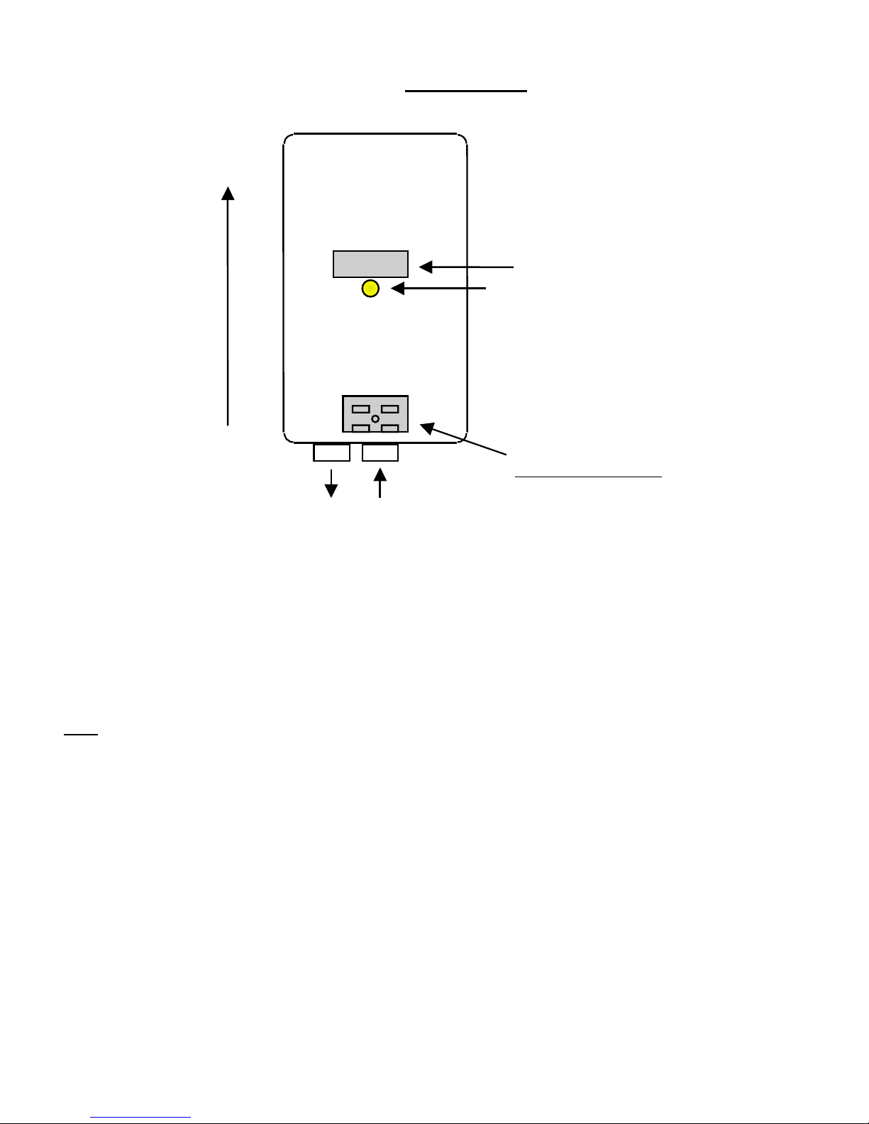
GENERAL
UP
Out In
Water outlet/inlet (Bottom)
This is how your “EFC” model should look when mounted correctly on the wall.
Refer to the U.L. rating label on the front cover of the unit to verify the unit is an
“EFC” model before continuing.
Any
other mounting configuration will prevent the unit from operating properly.
If the unit is mounted correctly and still does not produce hot water, look to see if the
indicator light illuminates when the hot water faucet is fully opened.
If the indicator light illuminates, turn to page 5.
If the indicator light does not illuminate, turn to page 3
All other possible situations turn to page 6.
Serial number
Indicator
light
U.L. Rating label
Model # = Order Ref. #
2
Page 3

The indicator light does not illuminate (When the hot water faucet is
fully opened):
STEP ONE:
Is the circuit breaker switched ON at the main circuit breaker panel?
YES Go to Step two
NO Run water at the hot water faucet, for a couple
of minutes, before
Then turn on the circuit breaker at the main
circuit breaker panel.
STEP TWO:
The unit will not heat unless sufficient water is flowing through the unit.
The minimum acceptable flow rate is 0.55 gallons per minute. Some
models require a higher flow rate, see chart below for specific model
flow rates. Measure the flow rate using the following procedure.
Fill a 1-gallon “milk” container and, using only water from the hot water outlet, record
the time (In seconds) required to fill. To calculate the flow rate, divide the number of
gallons the container holds (In this case one gallon) by the time required to fill.
e.g. If it takes 87 seconds to fill the container then the flow rate would be:
Flow rate (gpm) = v/t x 60 = 1 gal./87 sec. x 60 sec./1 min. = .69 gpm
Open all water valves completely. If the indicator light still does not illuminate then
proceed to STEP THREE.
MODEL TYPE / ORDER REF. # MINIMUM FLOW RATE
EFC-5500-4-S-10, EFC-6500-4-S-10 0.55 GPM
EFC-7500-4-S-10, EFC-8000-5-S-10,
EFC-8300-2-S-10 0.65 GPM
EFC-9000-5-S-10, EFC-9500-4-S-10,
EFC-10000-5-S-10 0.75 GPM
turning on the circuit breaker.
3
Page 4

Ω
STEP THREE:
A multimeter / voltmeter is required
to perform the following test.
TURN OFF THE CIRCUIT BREAKER BEFORE
PROCEEDING WITH THE NEXT TESTS.
DANGER!
V
A
Set the meter to the single ohms setting
Do not
measure continuity, this will not work.
The Ohm Symbol
(The upside down horseshoe)
NOTE: BE SURE THE ELECTRICITY IS TURNED OFF TO THE UNIT
Remove the front cover of the unit. At the end of the black heater body there are
two threaded silver rods with brass nuts on them (Where the wires connect). Take a
reading of the ohms value between these two rods and write it down (See the figure
below).
If the reading is less then 20 ohms on the single
(Rx1) scale or the (Rx10) scale then the
element is good, if it is much
greater.
e.g. 10,000 ohms or if you get a reading on the
(Rx1k), you will need to replace the element.
To do this contact Technical Service at 1-800334-3393 for replacement elements (Please
write down the resistance value, before
contacting Technical Service, this will be very
helpful to us. Also have the order ref. and the
serial numbers of the unit available for
Technical Service).
4
Page 5

The indicator light illuminates but water is not heated or the
STEP ONE:
water temperature is too low:
The water flow rate is too high. Reduce the water flow using the faucet. With
experimentation, an increase in water temperature should be observed. BE
CAREFUL, THE WATER EXITING THE FAUCET IS HOT. SCALD INJURY CAN
OCCUR FROM THE HOT WATER.
STEP TWO:
Make sure the unit is connected to the voltage supply specified on the U.L. rating
label located on the front cover of the unit.
STEP THREE:
Proceed to page 4 and follow STEP THREE.
Other possible solutions:
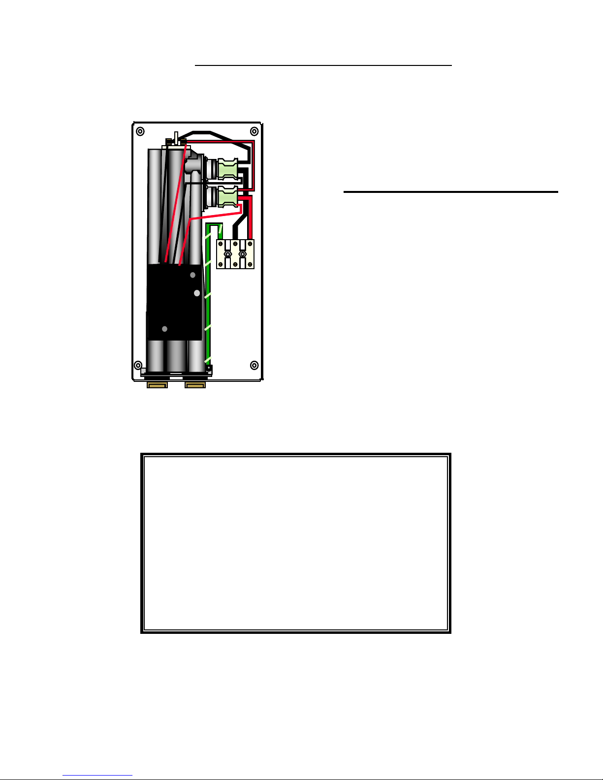
STEP ONE:
Note: Be sure electricity is turned “OFF” before proceeding.
Make sure the printed circuit board is mounted in the correct position. This is the top
set of mounting holes (See diagram below). Failure to mount the PCB in the correct
position will cause element burn out and may cause further damage to the unit.
(This board may have been incorrectly positioned if serviced previously).
The correct mounting holes
for the PCB on an “ES, EFT,
or EFC” model.
Board mounted in correct
position
Inlet filter
5
Page 6

STEP TWO
Inspect the inlet filter (See diagram above for location). Make sure the inlet filter
screen is free from debris, pipe dope or any other foreign materials, which may
prevent adequate water flow.
IF HAVING CARRIED OUT ALL THE TESTS LISTED ABOVE AND THE UNIT IS
STILL NOT FUNCTIONING, PLEASE CALL TECHNICAL SERVICE AT 1-800-
334-3393.
PLEASE HAVE THE FOLLOWING INFORMATION AVAILABLE:
1) ORDER REF. NUMBER (Located on U.L. rating label on the front cover of unit).
2) SERIAL NUMBER (Inside unit on back plate).
6
 Loading...