

Bradford White EF-60T-150E-3NA, EF-60T-199E-3NA, EF-100T-150E-3NA, EF-100T-199E-3NA, EF-100T-250E-3NA User Manual
...Page 1
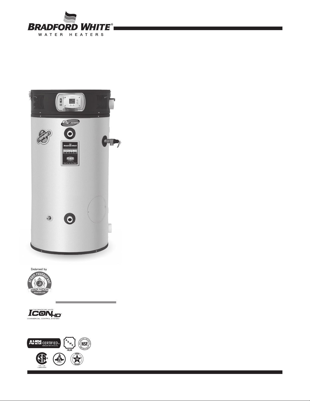
Commercial eF Series® Ultra High Efficiency
Gas Water Heater
The eF Series® Models feature:
■ Thermal Efficiency up to 99.1%—Ultra High Efficiency results in less fuel
FEATURING:
Photo is of
EF-60T-199E-3N
consumption and greater hot water recovery.
■ ICON HD
diagnostic codes, and system ignition functions into a single control board
with a digital LCD display.
■ ENERGY STAR
(150,199,250,399) Models.
■ Factory Installed Hydrojet
inlet sediment reducing device helps prevent sediment build up in the tank.
■ Direct Spark Ignition—For improved operational dependability and
durability.
■ Operation Mode—Two different digitally displayed operation modes have
the capability of adjusting the temperature setting up to 180°F (82°C), and
adjusting the degree setting (ºF to ºC, or ºC to ºF).
■ Service Mode—Eight different digitally displayed service screens can be
easily cycled through by pressing the select button. There is the capability
of adjusting the temperature setting up to 180°F (82°C), adjusting the
degree setting (ºF to ºC, or ºC to ºF), locking the maximum temperature
setting that can be adjusted in operation mode, displaying the temperature
sensor reading, displaying the flame current, and displaying diagnostic
codes.
■ Premix Power Burner—A self compensating negative regulation
system automatically increases or decreases fuel flow when a change
in combustion air is detected. This provides the range for optimum
combustion and efficiency (automatic high altitude compatibility).
■ Flexible Venting—The eF Series
either 2", 3" or 4" (51mm, 76mm or 107mm) PVC, CPVC or ABS (not
approved for Canada) vent pipe, and is approved for direct vent closed
combustion applications, or those applications that require inside air for
combustion. The eF Series
which means the air intake pipe doesn’t have to be vented the same
distance as the exhaust.
■ Ultra Quiet Operation.
■ A Single Exhaust Pressure Switch.
■ 1" (25mm) NPT Side Connections for Space Heating.
■ Sanitizing Capability—Temperature setting up to 180°F (82°C).
■ Complies with the latest ultra-low NOx requirement (14 ng/J NOx
limit).
■ ASME Code Available on All Models.
■ NSF Construction Available.
■ T&P Relief Valve—Installed.
■ Low Restrictive Brass Drain Valve—Durable tamper proof design.
™
—Intelligent proven design combines temperature control,
®
Models Available—EF60T125 & EF100T
®
Sediment Reduction System—Cold water
®
can vent vertically or horizontally with
®
is also approved for unbalanced venting,
3 or 5-Year Limited Tank Warranties / 1-Year Limited Warranty on Component Parts.
For more information on warranty, please visit www.bradfordwhite.com
For products installed in USA, Canada, and Puerto Rico. Some states do not allow limitations on warranties.
See complete copy of the warranty included with the heater.
MANUFACTURED UNDER ONE OR MORE OF THE FOLLOWING U.S. PATENTS: 5,682,666; 7,634,976; 5,660,165; 5,954,492; 6,056,542; 6,935,280; 5,372,185; 5,485,879; 5,574,822; 7,971,560; 7,992,526; 6,684,821;
7,334,419; 7,866,168; 7,270,087; 7,007,748; 5,596,952; 6,142,216; 7,699,026; 5,341,770; 7,337,517; 7,665,211; 7,665,210; 7,063,132; 7,063,133; 7,559,293; 7,900,589; 5,943,984; 8,082,888; 5,988,117; 7,621,238;
7,650,859; 5,761,379; 7,409,925; 5,277,171; 8,146,772; 7,458,341; 2,262,174. OTHER U.S. AND FOREIGN PATENT APPLICATIONS PENDING. CURRENT CANADIAN PATENTS: 2,314,845; 2,504,824; 2,108,186;
2,143,031; 2,409,271; 2,548,958; 2,112,515; 2,476,685; 2,239,007; 2,092,105; 2,107,012. eF Series
®
, Vitraglas® and Hydrojet® are registered trademarks of Bradford White® Corporation.
800-B-0418
Page 2
Commercial Gas High Efficiency Water Heater
V
eF Series® Additional Equipment Features:
Three Pass Heat Exchanger System—
Exchanger system keeps the hot combustion gases moving at
a high velocity. The combination of high turbulence and velocity
causes an enormous rate of heat transfer into the water.
Submerged Combustion Chamber—
combustion chamber in the center of the water storage tank
minimizes radiant heat loss and improves efficiency.
Zero Inch Clearance—
The eFSeries® jacket is cool to the
touch and is approved for zero inch clearance to combustibles for
unsurpassed installation flexibility.
Vitraglas® Lining—
An exclusively engineered enamel formula
that provides superior tank protection from the highly corrosive
effects of hot water. This formula (Vitraglas
surface by firing at a temperature of over 1600°F (871°C).
Protective Magnesium Anode Rods—
model has multiple anodes to provide added protection against
corrosion for long trouble-free service (EF100T399 has two
powered anode rods).
The three pass Heat
Submerging the
®
) is fused to the steel
Each eF Series®
Factory Installed Hydrojet® Sediment Reduction
System—
Cold water inlet sediment reducing device helps
prevent sediment build up in tank.
Water Connections—
Factory-installed true dielectric fittings
extend water heater life and simplify water line connections.
Hand Hole Cleanout—
Allows inspection of tank interior and
facilitates the removal of sediment deposits.
E.C.O.—
A manual re-set Energy Cut Off (E.C.O) shuts off all gas
in event of an overheat condition. The ECO is manually resettable.
Non-CFC Foam Insulation—
Covers the sides and top of
tank, reducing the amount of heat loss. This results in less energy
consumption, improved operation efficiencies and jacket rigidity.
EF-60T-150
EF-100T-150
Power
Direct Vent
15 ft.
15 ft.
Power
Direct Vent
50 ft.
50 ft.
Power
Direct Vent
75 ft.
75 ft.
Power
EF-60T-150
EF-100T-199
Power
EF-60T-150
EF-100T-199
Power
Vent
N/A
30 ft.
Vent
N/A
100 ft.
Vent
N/A
150 ft.
Air intake cannot exceed exhaust by more than 30 ft. in any venting situation. Subtract 5 ft.
for each additional 90° elbow.
2" Vent Pipe
Max. Intake Length
Max. Exhaust Length
3" Vent Pipe
Max. Intake Length
Max. Exhaust Length
4" Vent Pipe
Max. Intake Length
Max. Exhaust Length
6" Vent Pipe
Max. Intake Length
Max. Exhaust Length
EF-60T-125
Power
Direct Vent
15 ft.
15 ft.
EF-60T-125
EF-100T-150
Power
Direct Vent
60 ft.
60 ft.
EF-60T-125
EF-100T-150
Power
Direct Vent
85 ft.
85 ft.
EF-100T-399
Power
Direct Vent
120 ft.
120 ft.
Power
Vent
N/A
30 ft.
Power
Vent
N/A
120 ft.
Power
Vent
N/A
170 ft.
Power
Vent
N/A
240 ft.
eF Series® Optional Equipment Features:
Maxitrol Gas Pressure Regulating valve—
supply pressure to eF unit of 7" to 11" W.C. (provided incoming
Ensures proper
EF-60T-199
EF-100T-199
Power
Direct Vent
15 ft.
15 ft.
EF-60T-199
EF-100T-250
Power
Direct Vent
40 ft.
40 ft.
EF-60T-199
EF-100T-250
Power
Direct Vent
65 ft.
65 ft.
Power
Vent
N/A
30 ft.
EF-100T-300
Power
Vent
N/A
80 ft.
Power
Vent
N/A
130 ft.
Power
Direct Vent
30 ft.
30 ft.
Power
Direct Vent
55 ft.
55 ft.
Power
EF-100T-300
Power
Vent
N/A
60 ft.
Vent
N/A
110 ft.
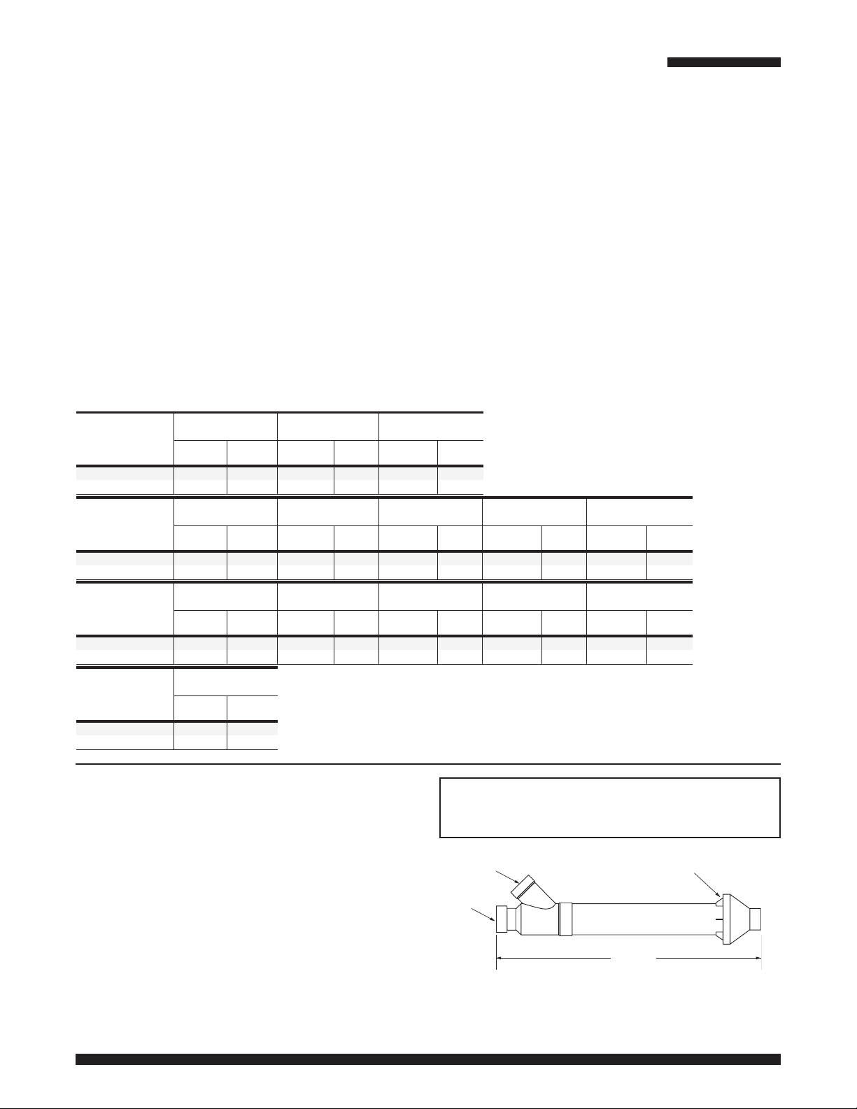
Concentric Vent Kit Termination—
EF-100T-399
Power
Direct Vent
25 ft.
25 ft.
EF-100T-399
Power
Direct Vent
50 ft.
50 ft.
Power
Vent
N/A
50 ft.
Power
Vent
N/A
100 ft.
3" termination fitting
provides for only one exit opening through wall or roof
(p/n 239-44069-01).
pressure is between 1/2 and 2 psi). This can be ordered as a
separate part, or as part of the heater. For the separate part,
please use p/n 243-45517-00. Part is included with EF100T399
model.
NSF Compliance Kit—
Low Inlet Gas Pressure Option—
p/n 265-44542-04.
Pre-assembled to allow
ent
Exhaust
Intake/
Combustion
Air
Rain Cap
operation with natural gas inlet pressure down to 3.5" w.c.
(Not available on EF-100T-300/399E-3N(A) models or any size
propane models.)
Optional Honeywell EnviraCOM™ Alarm Module—
Provides indication (contacts are closed) when an alarm is
present via normally open contacts (rated for up to 24 VAC).
Kit Number – 265-51961-00.
p/n 239-44069-02 (for 2” vent pipe only)
36 1/4"
p/n 239-44069-01
Page 3

Input
Input
Commercial Gas High Efficiency Water Heater
eF Series® Models
NATURAL GAS AND LIQUID PROPANE GAS
Model
Number
EF-60T-125E-3N(A)
EF-60T-150E-3N(A)
EF-60T-199E-3N(A)
EF-100T-150E-3N(A)
EF-100T-199E-3N(A)
EF-100T-250E-3N(A)
EF-100T-300E-3N(A)
EF-100T-399E-3N(A)
Model
Number
EF-60T-125E-3N(A)
EF-60T-150E-3N(A)
EF-60T-199E-3N(A)
EF-100T-150E-3N(A)
EF-100T-199E-3N(A)
EF-100T-250E-3N(A)
EF-100T-300E-3N(A)
EF-100T-399E-3N(A)
Nominal
Gal.
Capacity
U.S.
Gal.
60
60
60
100
100
100
100
100
Nominal
Liter
Capacity
227
227
227
379
379
379
379
379
Imp.
Gal.
50
50
50
83
83
83
83
83
BTU/Hr.
Input
125,000
150,000
199,999
150,000
199,999
250,000
300,000
399,999
kW/Hr.
Input
36.6
43.9
58.6
43.9
58.6
73.2
87.9
117.2
LP
BTU/Hr.
Input
125,000
150,000
199,999
150,000
199,999
250,000
300,000
399,999
LP
kW/Hr.
Input
36.6
43.9
58.6
43.9
58.6
73.2
87.9
117.2
Therm.
Eff.
%
96.0
93.0
92.0
99.1
98.5
97.0
92.0
94.0
Therm.
Eff.
%
96.0
93.0
92.0
99.1
98.5
97.0
92.0
94.0
A
Floor
to
Exhaust
Conn.
in.
5
5
5
5
5
5
5
5
A
Floor
to
Exhaust
Conn.
mm.
127
127
127
127
127
127
127
127
For propane gas models change suffix “N” to “X” and remove “E” from the
model number. Example: EF-100T-150-3X
(A) ASME - All models are available with ASME construction. To order ASME
construction add the (A) to the end of the model number.
Example: EF-60T-125E-3NA
For 5 year warranty models, change suffix
“3” to “5” Example: EF-100T-399E-5N
B
Jacket
Dia.
in.
1
28
/4
281/4
281/4
281/4
281/4
281/4
281/4
281/4
B
Jacket
Dia.
mm.
718
718
718
718
718
718
718
718
C
D
Floor
to
T&P
Conn.
in.
391/16
391/16
391/16
601/16
601/16
601/16
601/16
601/16
D
Floor
to
T&P
Conn.
mm.
992
992
992
1526
1526
1526
1526
1526
E
Floor
to
Gas
Conn.
in.
531/4
531/4
531/4
741/4
741/4
741/4
741/4
741/4
E
Floor
to
Gas
Conn.
mm.
1353
1353
1353
1886
1886
1886
1886
1886
Vent
Size
in.
3
3
3
3
3
3
3
3
C
Vent
Size
mm.
76
76
76
76
76
76
76
76
Note: The weight is the same for both ASME and Non-ASME models.
All models comply with the latest ultra-low NOx requirements of 14
ng/J or less.
14.0" w.c. maximum static, 4.5" w.c. minimum running (recommend
7.0" w.c. minimum running)
B
F
Floor
to
Top of
Heater
in.
3
56
/8
563/8
563/8
853/8
853/8
853/8
853/8
853/8
F
Floor
to
Top of
Heater
mm.
1432
1432
1432
2169
2169
2169
2169
2169
Meet or exceed ASHRAE 90.1b (current standard) C.E.C. Listed
H
Depth
in.
1
28
281/4
281/4
281/4
281/4
281/4
281/4
281/4
H
Depth
mm.
718
718
718
718
718
718
718
718
Floor to
Intake
Conn.
515/8
/4
515/8
515/8
725/8
725/8
725/8
725/8
725/8
Floor to
Intake
Conn.
1303
1303
1303
1837
1837
1837
1837
1837
J
Air
in.
J
Air
mm.
K
Floor
to Cold
Water
Conn.
in.
13
12
/16
1213/16
1213/16
1213/16
1213/16
1213/16
1213/16
1213/16
K
Floor
to Cold
Water
Conn.
mm.
325
325
325
325
325
325
325
325
3" PVC INLET
L
Floor
to Hot
Water
Conn.
in.
4115/16
4115/16
4115/16
6215/16
6215/16
6215/16
6215/16
6215/16
L
Floor
to Hot
Water
Conn.
mm.
1065
1065
1065
1599
1599
1599
1599
1599
Water
Conn.
NPT
in.
1
1
/2
11/2
11/2
11/2
11/2
11/2
11/2
11/2
Water
Conn.
NPT
mm.
38
38
38
38
38
38
38
38
Gas
Relief
Conn.
Valve
Size
Open
in.
3
/4
3
/4
3
/4
3
/4
3
/4
3
/4
3
/4
3
/4
Gas
Relief
Conn.
Valve
Size
Open
mm.
mm.
19
19
19
19
19
19
19
19
3
/4" NPT GAS INLET
in.
3
/4
3
/4
3
/4
3
/4
3
/4
1
1
1
19
19
19
19
19
25
25
25
Approx.
Shipping
Weight
lbs.
570
570
570
900
900
900
900
950
Approx.
Shipping
Weight
kgs.
259
259
259
408
408
408
408
431
GAS INLET
H
Recovery Data
Model
Number
EF-60T-125E-3N(A)
EF-60T-150E-3N(A)
EF-60T-199E-3N(A)
EF-100T-150E-3N(A)
EF-100T-199E-3N(A)
EF-100T-250E-3N(A)
EF-100T-300E-3N(A)
EF-100T-399E-3N(A)
30°F
485
564
740
601
792
980
1115
1519
1715/16"
1
/8"
1
T&P VALV E
364
423
558
450
597
735
836
1127
50°F
291
338
444
360
475
588
669
912
5
8
/8"
EXHAUST
3
7
/4"
AIR INTAKE
13
/16"
11
GPH Recovery at Degree Rise*
90°F
80°F
70°F
60°F
162
182
208
242
282
370
300
396
490
558
760
242
317
257
339
420
478
651
211
277
225
297
367
418
570
188
247
200
264
327
372
506
145
169
223
180
239
294
335
451
CLEANOUT
120°F
110°F
132
154
202
164
216
267
304
414
121
141
185
150
198
245
279
380
3
/4" O.D.
130°F
112
130
171
139
183
226
257
351
140°F100°F40°F
104
121
159
129
170
210
239
326
K
21/2" MIN.
17°C
1836
2135
2801
2275
2998
3710
4221
5750
1
/2" NPT OUTLET
1
F
1" NPT SPACE
L
HEATING OUTLET
1" NPT SPACE
HEATING RETURN
D
C
1
/2" NPT INLET
1
3" PVC EXHAUST
Note: Diagrams are for both 60 and 100 gallon models.
LPH Recovery at Degree Rise*
67°C
1378
1601
2112
1703
2260
2782
3165
4266
28°C
1102
1279
1681
1363
1798
2226
2532
3452
33°C
916
1067
1401
1136
1499
1855
2112
2877
39°C
787
916
1200
973
1283
1590
1809
2464
44°C
689
799
1049
852
1124
1389
1582
2158
50°C
613
712
935
757
999
1238
1408
1915
549
640
844
681
905
1113
1268
1707
61°C
500
583
765
621
818
1011
1151
1567
458
534
700
568
750
927
1056
1438
72°C
424
492
647
526
693
856
973
1329
E
J
A
78°C56°C22°C
394
458
602
488
644
795
905
1234
Page 4

Commercial Gas High Efficiency Water Heater
Sample Specification
The water heater shall be a Bradford White model EF-_____ with a rated storage capacity of not less than _____ gallons/ liters, a minimum
gas input of __________ BTU/hr., a minimum recovery of _____ GPH/LPH at 100°F (56°C) temperature rise, and a Thermal Efficiency Rating
of ____%. It shall be design certified by CSA International (formerly AGA and CGA) for 180°F (82°C) application, either with or without a
separate storage tank. The tank shall be lined with Vitraglas
have four extruded magnesium anode rods installed in separate head couplings. This water heater shall be equipped with stainless steel cold
water inlet, Hydrojet
®
Sediment Reduction System. The heater shall be insulated with Non-CFC foam. This water heater shall be equipped
with an electronic ignition system, an ASME rated T&P relief valve and a premix closed combustion system for direct venting using either
3" (76mm) or 4" (102mm) PVC, CPVC or ABS vent pipe. (115V AC required). The water heater shall be factory assembled and tested. The
water heater shall be approved for zero inch clearance to combustibles. A digital LCD display shall be integrated into the front and be an
adjustable electronic thermostat to any temperature up to 180°F. A recycling Energy Cut Off (E.C.O.) shuts off all gas in the event of an
overheat condition. The entire installation shall be made in compliance with state and local codes and ordinances.
General
All gas water heaters are certified at 300 PSI test pressure (2068 kPa) and 150 PSI working pressure (1034 kPa). All models are
design certified by CSA International (formerly AGA/CGA), ANSI standard Z-21.10.3, for up to 180°F (82°C) application as an
Automatic Storage Heater. As an Automatic Storage Heater, all models are complete, self-contained water heating systems. It
needs no separate storage tank, pump, wiring or elaborate piping network. When equipped with a mixing valve, it will supply
180°F (82°C) sanitizing and lower temperature general purpose hot water simultaneously. These models can be used either as
a single unit or in multiples connected in series or parallel (recommended).
Dimensions and specifications subject to change without notice in accordance with our policy of continuous product
improvement.
®
vitreous enamel and shall have a bolted hand hole cleanout. The tank shall
Ambler, PA
For field service, contact your professional installer or local Bradford White sales representative.
Sales 800-523-2931 n Fax 215-641-1612
Technical Support 800-334-3393
Warranty 800-531-2111
International: Telephone 1-215-641-9400 n Email international@bradfordwhite.com / www.bradfordwhite.com
©2018, Bradford White Corporation. All rights reserved.
n
n
Email techserv@bradfordwhite.com
Email warranty@bradfordwhite.com
Printed in U.S.A.800-B-0418
 Loading...