

EcoStor2
Gas Water Heaters
™
SERVICE
MANUAL
SUPPLEMENT
Solar
Troubleshooting Guide
SDW275S6BN shown above
and Instructions for Service
(To be performed ONLY by
qualified service providers)
Models Covered
by This Manual:
SDW2504T*F(BN,SX)
SDW265T*F(BN,SX)
SDW275S*(BN,SX)
SDW2TW50T*F(BN,SX)
SDW2TW65T*F(BN,SX)
SDW2TW75T*(BN,SX)
(*) Denotes Warranty Years
Manual 238-48244-00A 11/09
Save this manual for future reference

2
The Bradford White
EcoStor2™ Solar
Gas Water Heaters
Table of Contents
Page Service Procedure
How to use this manual 3 - - -
Introduction 4 - - -
Thermistor Wiring 5 - - -
Thermistor Wiring Test Procedure 6 ST-I
Gas Control Temperature Sensor 7 - - -
Temperature Sensor and Harness Testing 8 ST-II
Temperature Sensor Measurement 9 ST-III
Solar Thermal Troubleshooting 10 - - -
Solar Thermal Parts List (Atmospheric) 11 - - -
Solar Thermal Parts List (Ultra Low NOx) 12 - - -
Solar Thermal Parts List (TTW) 13 - - -
Notes 14 - - -
2
3
It is intended for this manual to be used by qualified service personnel for the
primary purpose of troubleshooting and repair of the Bradford White EcoStor2™
Solar with Gas Backup Water Heaters. Understanding the solar thermal sequence
of operation section of this manual will contribute greatly to troubleshooting the
water heater.
This manual serves as a water heater supplement to service and troubleshoot
specifically the solar features of the water heater. Please refer to the table below to
determine which base model service manual is appropriate for the non-solar
features of the water heater.
EcoStor2™ Solar
Solar Model Base Model
SDW4U5036FRN U45036FRN
SDW2504T6F(BN,SX) M2XR504T6F(BN,SX)
SDW2TW50T6F(BN,SX) M2TW50T6F(BN,SX)
SDW2U65T6FRN U2XR65T6FRN
SDW265T6F(BN,SX) M2XR65T6F(BN,SX)
SDW2TW65T6F(BN,SX) M2TW65T6F(BN,SX)
SDW275S6(BN,SX) M2XR75S6(BN,SX)
SDW2TW75T6(BN,SX) M2TW75T6(BN,SX)
Service Manual
238-47132-00
238-44923-00
238-46238-00
238-47132-00
238-44943-00
238-46238-00
238-46647-00
238-47150-00
How to use this Manual
3

4
The Bradford White EcoStor2 Solar Water Heater System
The new Bradford White Solar with Gas Backup water heaters are designed to provide
reliable performance with enhanced standard features. New design features include
an internal double-wall, atmospherically vented heat exchanger for safe and effective
heat transfer, a gas control temperature sensor in the upper portion of the water heater
to maximize solar efficiency and thermistor wires to allow seamless connection to a
solar controller.
Double-wall Heat Exchanger—An atmospherically vented double-wall heat
exchanger allows an internal heat exchanger to safely use a propylene glycol/water
mix commonly applied in solar thermal heating systems. In the unlikely event that
either wall of the heat exchanger leaks, the fluid will follow a vent path to exit the water
heater through the heat exchanger fitting. This fluid will run down the outside of the
water heater to indicate a leak to the home owner.
Having an immersed heat exchanger enhances heat transfer, being able to heat
directly to the potable water.
Gas Control Temperature Sensor—A temperature sensor located in the upper
portion of the water heater allows the solar thermal system to maximize the solar
collector efficiency. This is due to the potential low temperatures observed in the tank
bottom where the immersed heat exchanger is located. The gas backup will only heat
the water when the solar thermal system is not producing enough heat to keep the gas
control temperature sensor at the temperature level indicated on the gas control,
thereby requiring the backup heat.
Thermistor Wiring—Thermistor wiring is provided to allow thermistor connection to
the solar thermal control without running wires outside the water heater. Thermistors
are not included due to multiple thermistor possibilities with the various solar thermal
controls that may be installed on-site. There are 2 pair of wires provided; one in the
lower portion of the tank to allow the temperature difference to be read between the
water heater and the solar collector, and a second in the upper portion of the water
heater to allow a solar control to read the expected delivered temperature.
This service manual supplement is designed to facilitate problem diagnosis and
enhance service efficiency. To further promote quicker service times , the gas valve
can be removed and replaced without draining the water heater. A special tool is
required and will be provided with each gas valve kit shipped from our Service Parts
department.
Please read the service manual supplement completely before attempting service on
this new series of solar thermal models.
EcoStor2™ Solar
Introduction
4
5
This section is intended to provide a better understanding of the solar thermal design
application and how it varies from the base model listed on page 3.
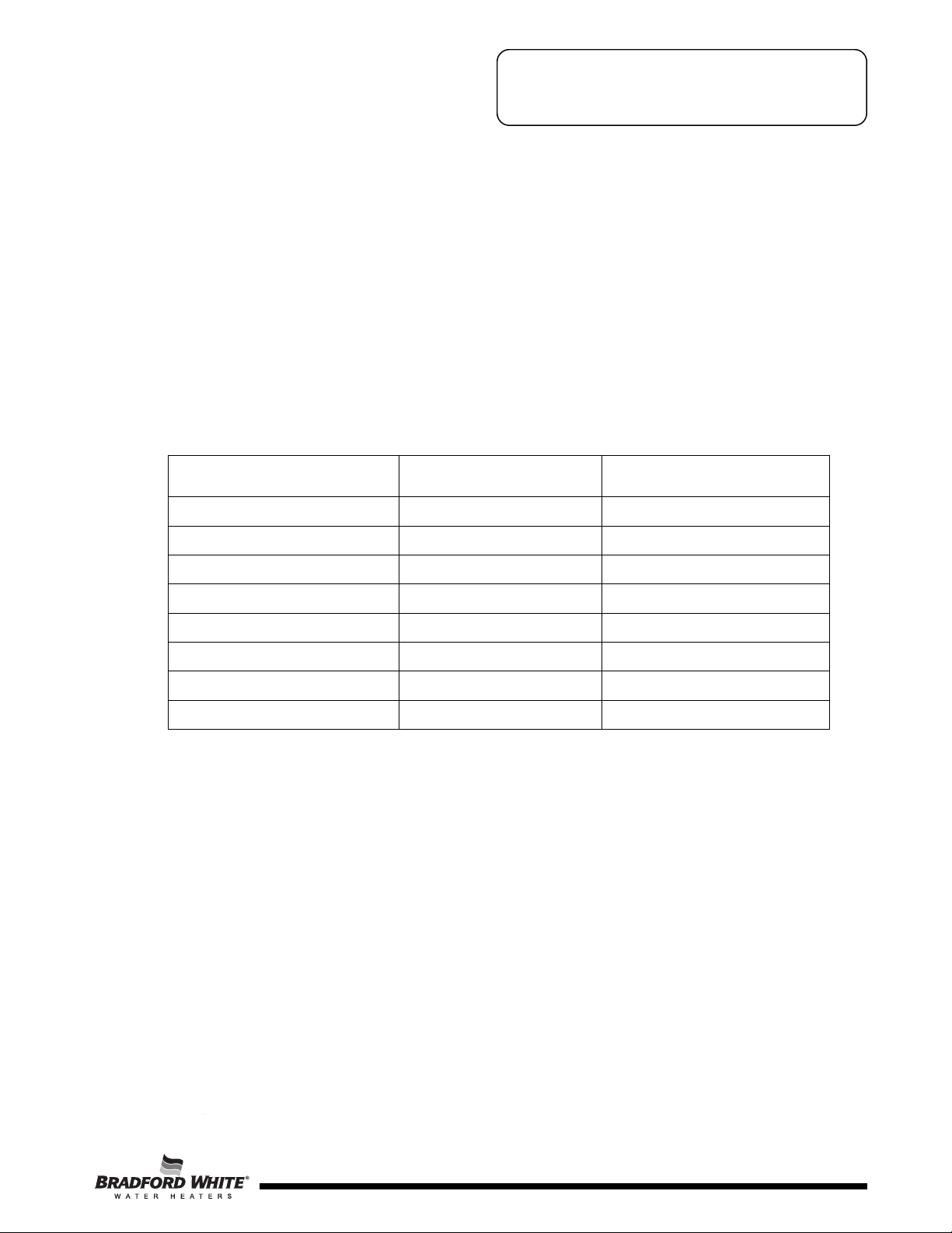
Solar Thermistor Wiring
The solar with gas backup water heater comes provided with two sets of twisted
thermistor wiring. They are color coded for ease of use.
The solar with gas backup models come with an internal double-wall heat exchanger.
Brown thermistor wiring is provided under an access panel between the solar heat
exchanger connections. A thermistor (not included) wired to this pair can be
connected to the solar control to determine the temperature differential between the
tank and the solar collector. The control can then activate a circulator to heat the tank.
To assist in connecting the thermistor, the end has a supplied wire nut. A bracket and
plate is supplied to mechanically press the thermistor against the tank wall.
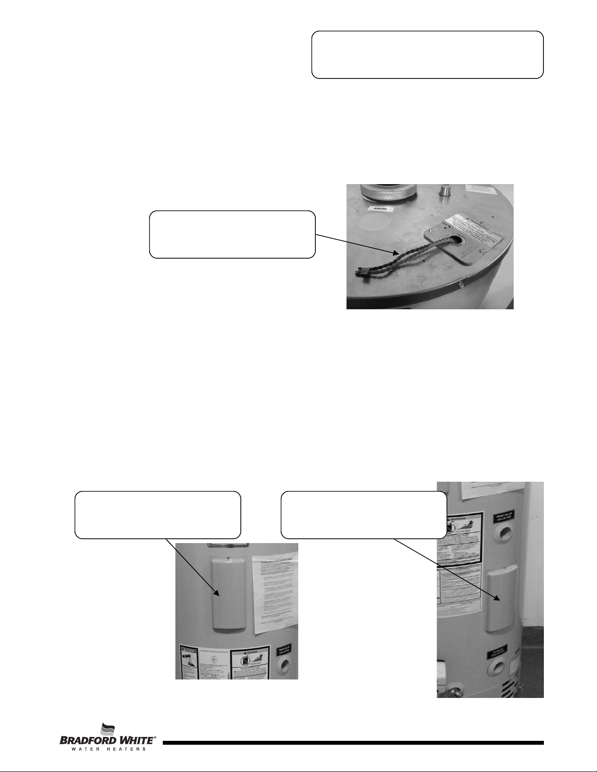
A twisted orange wire set is provided under the upper access panel. Some solar
controllers have locations for a second tank temperature input. This is not used for
controlling the solar thermal system, but helps the end user understand what an
anticipated delivered temperature may be.
EcoStor2™ Solar
Thermistor Wiring
Brown and Orange twisted
thermistor wires
Upper Access Location
(Orange Twisted Pair)
Lower Access Location
(Brown Twisted Pair)
5

6
Thermistor Wire Testing
Step 1. Disconnect and unplug the solar control.
Step 2. Disconnect the thermistor twisted pair from the control or control sensor wiring.
Step 3. Connect a multimeter set to read ohms to the twisted wire stripped ends.
Determine the resistance value of the attached thermistor. NOTE: The
thermistor is field supplied and various
thermistors have different ohm values
for different temperatures. Refer to the
temperature specification sheet for the
thermistor installed on the water heater
to determine if the resistance value is
correct.
The image to the side shows a
resistance value for a thermistor at
ambient temperature connected under
the lower access cover (brown twisted
pair). The same procedure can be
followed to determine if the upper
thermistor value is correct.
Step 4. If the multimeter indicates a resistance that does not match the actual
temperature of the thermistor, replace the thermistor. Reconnect the wiring,
verify that the new thermistor does match, and reconnect to the solar control.
Turn on the power to the solar control.
If the multimeter indicates a short or open, disconnect the thermistor from the
connection made under the access cover. Measure the thermistor ohm value
directly. If the multimeter indicates an open, replace the thermistor.
If the multimeter indicates an appropriate ohm value, determine which wire is
open by measuring directly from one end of the wire to the other, or if short;
verify by measuring both wire ends from the same location. If the wiring
cannot be fixed, the wiring for the thermistor may have to be ran on the
outside of the water heater. Replace the wiring, and reconnect it to the solar
control. Turn on the power to the solar control.
EcoStor2™ Solar
ST-I Thermistor Wiring
Test Procedure
6

7
The solar with gas backup water heater senses temperature from the upper portion of
the tank. This allows the solar thermal heating system to maximize the ability to heat
the water inside the tank. Only when the upper portion of the water heater tank
reaches the water temperature to turn on the gas control, does the backup heat begin.
This is achieved by placing a thermistor sensor inside a thermal well and connecting
the sensor by means of a wire harness to the gas control. The thermistor well, sensor
and wire harness connection is located under the top access cover.
NOTE: Depending on the solar with gas backup model, the gas control may vary.
Refer to the base model service manual as indicated on page 3.
EcoStor2™ Solar
Gas Control
Temperature Sensor
Thermistor sensor
in well
Thermistor sensor
outside well
Wire harness
connection to
thermistor
Wire harness connected
to the gas control
Wire harness plug in
location to the gas control
7

8
EcoStor2™ Solar
CAUTION
DO NOT use standard multimeter probes for this test. Doing
so will damage connector. Use special pin type electronic
probes or small diameter wire pins inserted into connector.
Disconnect thermal
well wire harness
If the control has gone into lockout due to
excessive tank temperature (four flash, 3
second pause) reset the control by rotating
the gas control knob to “OFF” position. Then
follow the lighting instructions and return the
gas control knob to the desired setpoint.
Observe the water heater operation. If
the gas control continues to lockout due
to excessive tank temperature, proceed
to thermal sensor and harness testing to
determine the cause.
THERMAL SENSOR AND
HARNESS TESTING
Position the gas control knob to the
“OFF” position and disconnect the
thermal sensor harness from the gas
control.
Using a multi-meter set to the
Ohms setting, determine the
resistance of thermal sensor .
(see caution photos at right)
Once the thermal sensor resistance values are
known, the water temperature must also be known
to determine if the resistance values are correct.
See page 9 to obtain water temperature.
Are thermal sensor and harness
resistance values correct?
Repeat Ohm measurement at the
sensor connector.
Are thermal sensor resistance
values correct?
N
Replace gas
control
Y
Using a multi-meter set to the ohms setting, insert one meter probe (see
caution) into center wire position of thermal well connector, insert the second
probe (see caution) into either of the outside wire positions (see photo on left).
Alternate the probe on the outside position to the opposite outside wire position
(see photo on right).
Replace thermal
well sensor
Replace sensor
wire harness
YN
ST-II Temperature Sensor
and Harness Testing
8

9
DETERMINE THE WATER TEMPERATURE INSIDE THE STORAGE TANK
EcoStor2™ Solar
°F0123456789
40 26109 25400 24712 24045 23399 22771 22163 21573 21000 20445
50 19906 19383 18876 18383 17905 17440 16990 16553 16128 15715
60 15314 14925 14548 14180 13823 13477 13140 12812 12494 12185
70 11884 11592 11308 11032 10763 10502 10248 10000 9760 9526
80 9299 9078 8862 8653 8449 8250 8057 7869 7685 7507
90 7333 7165 7000 6839 6683 6531 6383 6238 6098 5961
100 5827 5697 5570 5446 5326 5208 5094 4982 4873 4767
110 4663 4562 4464 4368 4274 4183 4094 4006 3922 3839
120 3758 3679 3602 3527 3453 3382 3312 3244 3177 3112
130 3048 2986 2925 2866 2808 2752 2697 2643 2590 2538
140 2488 2439 2391 2344 2298 2253 2209 2166 2124 2083
150 2043 2004 1966 1928 1891 1856 1820 1786 1753 1720
160 1688 1656 1625 1595 1566 1537 1509 1481 1454 1427
170 1402 1376 1351 1327 1303 1280 1257 1235 1213 1191
180 1170 1150 1129 1110 1090 1071 1953 1035 1017 999
190 982 965 949 933 917 901 886 871 857 842
200 828 814 801 788 775 762 749 737 725 713
In Degrees F
Step 1. Set the Gas Control knob to the “OFF” position.
Step 2. Turn off inlet water supply to water heater.
Step 3. Draw approximately 4 gallons of water from drain valve into a container, or
suitable drain, and discard. Draw an additional gallon and immediately measure
water temperature using an accurate thermometer. It may be necessary to open
a hot water faucet to allow water heater to drain.
Step 4. Using the chart below, determine correct resistance value for the water
temperature from step 3.
Example: If the temperature of the water is 84°F, then the resistance through the
sensor would be 8449 (see shaded area). NOTE: Sensor resistance
increases as the temperature decreases.
NOTICE
It is important to understand once the resistance for the temperature sensor is determined
from the previous page, water flow through the water heater should not occur. Prior to drawing water from drain valve, turn off the cold water supply to the water heater. This will prevent
cold water flow into the tank affecting the resistance value of the temperature sensor.
WARNING
Stored water may be HOT when performing the following steps in this procedure.
Take necessary precaution to prevent personal injury.
ST-III Temperature Sensor
Measurement
9

10
EcoStor2™ Solar
This troubleshooting chart serves as a water heater supplement to troubleshoot
specifically the solar features of the water heater. Please refer to page 3 to determine
which base model service manual is appropriate for the non-solar troubleshooting
chart for the water heater.
EcoStor2™ Solar
Solar Thermal
Troubleshooting Chart
SYMPTOM PROBABLE CAUSE CORRECTIVE ACTION
SERVICE
PROCEDURE
Not enough
hot water
1. Gas control
temperature sensor
out of spec.
2. Improperly sized
solar collector(s).
3. Gas backup not
functioning.
4. Solar thermal
system not
functioning.
1. Verify accurate
temperature is sensed.
2. Review calculations to
determine appropriate
collectror array.
3. Review service manual
for base model.
4. Review solar thermal
system for
functionality.
1. See service
procedure ST-II.
10

11
EcoStor2™ Solar
29 Thermostat Sensor Wire Harness
30 Solar Sensor Wire Harness
31 Burner Assembly Complete
32 Burner
33 Main Burner Orifice
34 Pilot Assembly
35 Pilot Orifice
1 Draft Hood
2 Hex Head Anode Aluminum
3 Heat Trap Insert
4
Hot Water Outlet Anode Aluminum
5 Cold Water Inlet Polysulfone (NC Code)
6 Flue Baffle Complete
7 Junction Box Cover
8 Conduit Cover/Ground
9 T&P Relief Valve
10 Thermostat Bracket Assembly
11 Access Cover
12 Outer Door
13 Screw-#6-20 x 3/8 PHCR
14 Nat. Gas Resettable Thermal Switch
15 Nat. Gas Right Side Inner Door Complete
16 Screw-#8-18 x 3/4 HWH
17 Left Side Inner Door Complete
18 Screw-#10-12 x 3/4 HWH
19 Brass Drain Valve
20
Wire Harness (Gas Control to Resettable
Thermal Switch)
21 Gas Control Natural Gas (w/ Service Tool)
22 Gas Control Service Tool
23 Control Bracket
24 Thermostat Sensor
25 Thermostat Sensor Well
26 Inner Door Gasket Kit
27 ASSE Approved Mixing Valve (Optional)
28 Universal Integrated Mixing Device Kit (IMD)
Solar Thermal Parts List
(Atmospheric)
11

12
EcoStor2™ Solar
1
Draft Diverter
2
Hex Head Anode (Aluminum)
3 Heat Trap Insert
4 Hot Water Outlet Anode (Aluminum)
5 Cold Water Inlet Polysulfone (NC Code)
6 Flue Baffle
7
Junction Box Cover
8 Conduit Cover/Ground
9 T&P Relief Valve
10 Thermostat Bracket Assembly
11 Access Cover
12 Screw-#8-18 X 3/4 HWH
13 Screw-#10-12 X 3/4 HWH
14 Right Side Inner Door Complete
1
5 Screw-#6-20 X 3/8 PHCR
16 RTD Sensor
17 Outer Door
18 Brass Drain Valve
19
Wire Harness (Gas Control to Resettable
Thermal Switch)
20 Gas Control (w/ Service Tool)
21 Gas Control Service Tool
22 Gas Control Bracket
23 Thermostat Sensor
24 Thermostat Sensor Well
25 Inner Door Gasket Kit
26 ASSE Approved Mixing Valve (Optional)
27 Universal Integrated Mixing Device Kit (IMD)
28 Burner Assembly
29 Manifold Mount
30 Orifice
31 Flexible Gas Feedline
32 Resettable Thermal Switch
33 Burner
34 Pilot Assembly Kit
35 Screw-#8-18 X 1/2 TEK
36 Pilot Orifice
37 Thermopile Kit
38 Thermostat Sensor Wire Harness
39 Solar Sensor Wire Harness
Solar Thermal Parts List
(Ultra Low NOx)
12

13
EcoStor2™ Solar
Solar Thermal Parts List
(TTW)
34 Inner Door Gasket Kit
35 ASSE Approved Mixing Valve (Optional)
36 Universal Integrated Mixing Device Kit (IMD)
37 Thermostat Sensor Wire Harness
38 Solar Sensor Wire Harness
1 Blower Complete
2 Air Mixing Inlet
3 Pressure Switch
4 Blower Temperature Switch
5 Blower Gasket
6
Blower Power Cord
7 3" Exhaust Adaptor w/Vent Terminal
8 Condensate Hose Kit (Optional)
9 Heat Trap Insert
10 Hot Water Outlet Aluminum
11 Flue Baffle
12 Hex Head Anode Aluminum
13 Cold Water Inlet
14 Safety Circuit Wire Harness
15 T&P Relief Valve
16 Outer Door
17 Right Side Inner Door Complete
18 Screw-#8-18 x 3/4 HWH
19 Left Side Inner Door Complete
20 Screw-#10-12 x 3/4 HWH
21 Brass Drain Valve
22 Flammable Vapor Sensor Clip
23 Flammable Vapor Sensor
24
Flammable Vapor Sensor Harness/
Simulated Resistive Device
25 Control Bracket
26 Gas Valve Natural Gas
27 Gas Valve Service Tool
28 Temperature Sensor Well
29 Temperature Sensor
30 Solar Sensor Bracket Assembly
31 Access Cover
32 Cover Junction Box
33 Cover Conduit/Ground
39 Burner Assembly Complete
40 Burner
41 Main Burner Orifice
42 Pilot Assembly
43 Pilot Orifice
13

NOTES
14

NOTES
15

Email
parts@bradfordwhite.com
techserv@bradfordwhite.com
www.bradfordwhite.com
 Loading...