

Page 1
SOLAR WATER HEATER WITH
pp
ELECTRIC BACKUP
A Spanish language version of these instructions is available by contacting the manufacturer listed on the rating plate.
La version espanola de estas instruccions se puede obtener al escribirle a la fábrica cuyo nombre aparece in la placa de
especificaciones.
INSTALLATION/OPERATING MANUAL
WITH PARTS LISTING AND TROUBLESHOOTING GUIDE
WARNING
To avoid damage or injury, there
must be no materials stored against
the solar water heater and proper
care shall be taken to avoid
unnecessary contact (especially by
children) with the solar water heater.
Do not store or use gasoline
or other flammable liquids
in the vicinity of this water
heater or any other
liance.
a
For your family’s comfort, safety, and convenience, we recommend this water
heater/storage unit be installed and serviced by a plumbing professional.
238-47073-00C REV 11/08
Page 2

CONGRATULATIONS!
You have just purchased one of the finest water heaters on the
market today!
This installation, operation, and instruction manual will explain in
detail the installation and maintenance of your new solar water
heater. We strongly recommend that you contact a plumbing
professional for the installation of this water heater.
We require that you carefully read this manual, as well as the
enclosed warranty, and refer to it if questions arise. If you have
any specific questions concerning your warranty, please consult
the plumbing professional from whom your water heater was
purchased. For your records we recommend that you write the
model, serial number and installation date of your solar water
heater in the back of this manual.
This manual should be kept with the solar water heater.
We’re committed to providing you with the finest water heater
made.
2
Page 3
SECTION I
IMPORTANT INFORMATION
The equipment must be installed in accordance with those installation regulations required in the
area where the installation is to be made. These regulations must be carefully followed in all cases.
Authorities having jurisdiction shall be consulted before installations are made.
All wiring on water heaters installed in the USA must be in accordance with the National Electrical Code,
ANSI/NFPA 70, latest edition, and/or local regulations; or in Canada, installed in accordance with the
Canadian Electrical Code, CSA C22.1, latest edition and/or local regulations.
The following terms are used throughout this manual to bring attention to the presence of hazards of
various risk levels, or to important information concerning product life.
DANGER
Indicates an imminently hazardous
situation, which, if not avoided, will
result in death, serious injury, or
substantial property damage.
WARNING
Indicates a potentially hazardous
situation, which, if not avoided, could
result in death, serious injury, or
substantial property damage.
I- IMPORTANT INFORMATION…………….….. 3
II- SPECIFICATIONS………………………………. 6
III- GENERAL INFORMATION……………………. 8
IV- PRE-INSTALLATION…………………………… 10
TABLE OF CONTENTS
V- WATER CONNECTIONS………………………..
ONE-TANK SYSTEM INSTALLATION………………...
TWO-TANK SYSTEM INSTALLATION……...………...
VI- ELECTRICAL CONNECTIONS……………….. 19
VII- OPERATING INSTRUCTIONS………………… 21
VIII- MAINTENANCE…………………………………. 23
IX- TROUBLESHOOTING GUIDE………………… 25
X- PARTS LIST……………………………………… 26
XI- NOTES ……………………………………………. 28
-READ CAREFULLY-
Indicates a potentially hazardous
situation, which, if not avoided,
may result in moderate, or minor
injury or property damage.
Indicates special instructions on
installation, operation or
maintenance, which are important
but not related to personal injury
hazards.
CAUTION
NOTICE
12
13
15
3
Page 4
Important Information continued-
DANGER
DO NOT store or use gasoline or other flammable, combustible, or corrosive vapors and/or liquids in the
vicinity of this or any other appliance.
IF YOU SMELL GAS:
DO NOT try to light any appliance.
DO NOT touch any electric switch; do not use any telephone in your building.
Immediately call your gas supplier from a telephone in another building. Follow the gas supplier’s
instructions.
If you cannot reach your gas supplier, call the fire department
DO NOT OPERATE THE APPLIANCE UNTIL THE LEAKAGE IS CORRECTED!
Liquefied petroleum gas/propane gas is heavier than air and will remain at floor level if there is a leak.
Basements, crawl spaces, closets, and areas below ground level will serve as pockets for accumulation of
leaking gas.
This water heater is supplied with adjustable thermostat(s) to control water temperature. Hot water
temperatures required for automatic dishwasher and laundry use can cause scald burns resulting in serious
personal injury and/or death. The temperature at which injury occurs varies with the person’s age and the
time of exposure. The slower response time of disabled persons increases the hazards to them. NEVER
small children to use a hot water tap or to draw their own bath water. NEVER
leave a child or disabled
person unattended in a bathtub or shower.
allow
WARNING
Installation is not complete unless a properly sized/capacity pressure and temperature relief valve is installed
into the side of the water heater. See the General Information section of this manual for details.
This water heater contains very hot water under high pressure. Do not unscrew any pipe fittings or attempt
to disconnect any components of this water heater without positively assuring the water is cool and has no
pressure. Always wear protective clothing and equipment when installing, starting up, or servicing this water
heater to prevent scald injuries. Do not rely on the pressure and temperature gauges to determine the
temperature and pressure of the water heater. This water heater contains components that become very hot.
Do not touch any components unless they are cool.
Improper installation, adjustments, alteration, service or maintenance can cause property damage, personal
injury or loss of life. Failure to follow all instructions in the proper order can cause personal injury or death.
Read and understand all instructions, including all those contained in component manufacturer’s manuals,
which are provided with the appliance before installing, starting-up, operating, maintaining, or servicing this
appliance. Keep this manual and literature in legible condition and posted near the appliance for reference
by owner and service technician.
This water heater requires regular maintenance and service to operate safely. Follow the instructions
contained in this manual.
Installation, maintenance, and service must be performed only by an experienced, skilled, and knowledgeable
installer or service agency.
4
Page 5
Important Information continued-
WARNING
It is the responsibility of the installing contractor to see that all controls are correctly installed and are
operating properly when the installation is complete.
DO NOT operate the water heater with jumpered or absent controls or safety devices.
DO NOT tamper with or alter the water heater and/or controls.
DO NOT operate the water heater if any external part or control has been submerged in water. Immediately
call a qualified service technician to inspect the appliance and to replace any part of the control system that
was under water.
This water heater is suitable for installation on combustible flooring. DO NOT install this water heater on
carpeting.
DO NOT operate this water heater without first being certain it is filled with water.
Flammable items, pressurized containers, or any other potential fire hazardous articles must never be placed
on or adjacent to the heater. Containers of flammable gases should not be stored or used in the same room
with this water heater.
Hydrogen gas can be produced in an operating water heater that has not had water drawn from the tank for
a long period of time (generally two weeks or more). Hydrogen gas is extremely flammable.
possibility of injury under these conditions, it is recommended that a water faucet be opened for several
minutes at the kitchen sink before you use any electrical appliance that is connected to the hot water system.
If hydrogen is present, there will be unusual sounds such as air escaping through the pipes as hot water
begins to flow. Do not smoke or have open flame near the faucet at the time it is open.
To prevent the
The maximum supply temperature from the solar collector must not exceed 250°F (121°C).
5
CAUTION
Page 6
SECTION II
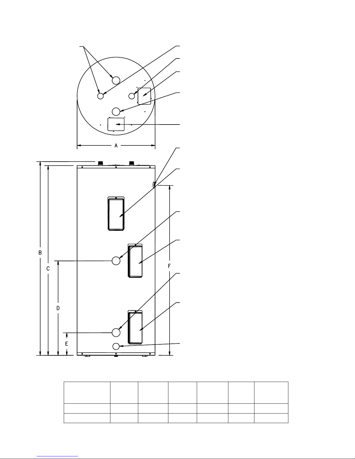
SPECIFICATIONS
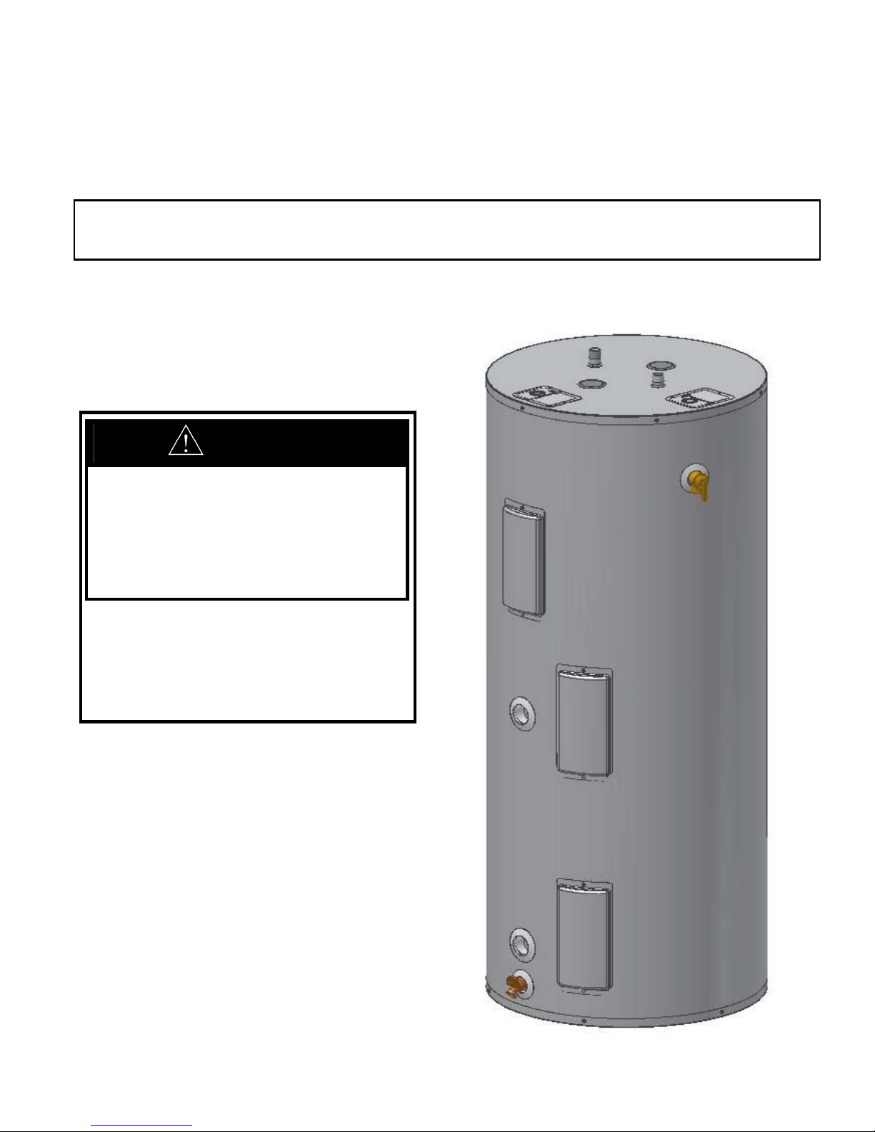
ANODES
HOT WATER OUTLET - 3/4" NPT
COLD WATER INLET - 3/4" NPT
SOLAR SENSOR WIRING
JUNCTION BOX
OPTIONAL OUTLET
FOR RECIRCULATION
(60 & 75 GAL. MODELS)
ELECTRIC HIGH VOLTAGE
WIRING JUNCTION BOX
TEMPERATURE AND PRESSURE
RELIEF VA LUE OPENING
UPPER COVER:
SOLAR THERMISTOR W IR ES,
THERMOSTAT, UPPER HEATING
ELEMENT UNDER C O V ER
Figure 1 – Tank Layout
Table 1: Water Heater Dimension (Inches)
FROM SOLAR COLLECTOR :
SINGLE -WALL EXCHANG ER - 1 " N PT
DOUBLE-WALL EXCHANGER - 3/4" NPT
MIDDLE COVER:
THERMOSTAT UNDER COVER IN
DUAL HEATING ELEMENT MODELS
TO SOLAR C OLLECTOR :
SINGLE -WALL EXCHANG ER - 1 " N PT
DOUBLE-WALL EXCHANGER - 3/4" NPT
LOWER COVER:
SOLAR THERMISTOR W IR ES,
LOWER HEATING ELEMENT UNDER
COVER IN DUAL ELEMENT MODELS
DRAIN COUPLING - 3/4" NPT
DRAIN VALVE - 5/8" NH
MODE
L
60-Gal. 22 60-1/4 59-1/4 29-1/2 7-3/8 53
75-Gal. 24 60-1/4 59-1/4 29-1/2 7-3/8 53
6
A B C D E F
Page 7

115-Gal. 28 1/4 63-1/4 62-1/2 29-1/2 7-3/8 55-3/4
7
Page 8
Specifications continued-
Table 2: Single-wall Exchanger Solar Water Heater Capacities
MODEL
Tank
Capacity
(Gal)
Coil
Volume
(Gal)
Coil Heat
Transfer Area
(Sq Ft)
Approximat
e
Dry Weight
Approximate
Wet Weight
(Lbs)
(Lbs)
60-Gal. 60 2.5 14.2 212 697
75-Gal. 75 2.5 14.2 236 832
115-Gal. 115 2.5 14.2 340 1248
Table 3: Double-wall Exchanger Solar Water Heater Capacities
MODEL
Tank
Capacity
(Gal)
Coil
Volume
(Gal)
Coil Heat
Transfer Area
(Sq Ft)
Approximat
e
Dry Weight
Approximate
Wet Weight
(Lbs)
(Lbs)
60-Gal. 60 2.5 14.2 217 702
75-Gal. 75 2.5 14.2 241 837
115-Gal. 115 2.5 14.2 345 1253
Table 4: Electric Backup Water Heater Ratings with ASSE Approved Thermostatic Mixing Valve
First Hour Supply (Gallons)
MODEL
Single Element Dual Element
60-Gal 46 84 1.1
75-Gal 53 97 0.9
115-Gal 83 124 0.7
Standby Heat
Loss Rating
(°F/Hr)
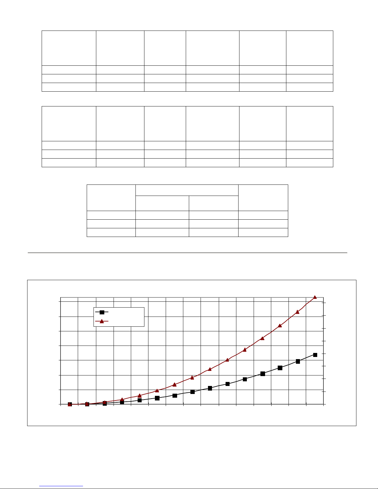
Heat Exchanger Flow Specifications
H eat Exchang er Pressure Dro p Curve
7.00
6.00
5.00
4.00
3.00
(PSID)
2.00
Total Pressure Drop
1.00
0.00
01234567891011121314
Singl e-wall
Double-wall
Flowrate (GPM )
Figure 2 – Solar Heat Exchanger Pressure Drop Chart
16.00
14.00
12.00
10.00
8.00
6.00
4.00
2.00
0.00
Head Loss(Feet)
Total
8
Page 9

FEATURES
This water heater contains the following features:
HEAT EXCHANGER – The heat exchanger (coil) is made of porcelain coated carbon steel tubing and female
fittings. If a confirmed leak occurs, contact the plumbing professional who installed the water heater or the
manufacturer listed on the rating plate, for additional guidance.
DOUBLE-WALL HEAT EXCHANGER MODELS –Water heaters that have a double-wall heat exchanger have a
slight gap between the two tubes that makes up the heat exchanger coil. The ¾” female fitting provides an
atmospheric vent for any fluid that enters the gap between the tubes.
SINGLE-WALL HEAT EXCHANGER MODELS – Water heaters that have a single-wall heat exchanger have a
solid tube that makes up the exchanger coil with a 1” female fitting. Water heaters with single-wall heat exchangers
meets the Uniform Plumbing Code for installation in all potable water systems provided that:
• The heat transfer medium (including additives) is practically non-toxic, having toxicity rating of class of 1 as listed in
Clinical Toxicology of Commercial Products.
• The heat transfer medium pressure is limited to maximum 30 psig by approved relief valve.
• The heat transfer medium is potable water or contains only substances that are recognized as safe by the U.S. Food
and Drug Administration (FDA).
• The pressure of the heat transfer medium is maintained less than the normal minimum operating pressure of the
potable water system.
• The equipment is permanently labeled to indicate that only additives recognized as safe by the FDA shall be used
in the heat transfer medium.
BACKUP HEATING ELEMENT(S) WITH ADJUSTABLE THERMOSTATS – The water temperature may be
adjusted from approximately 100°F to approximately 180°F. The thermostats are factory set at 120°F. It is
recommended that lower temperatures be used to avoid the risk of scalding. Refer to the “Warnings” in the section
on SCALDING in Section VII, OPERATING INSTRUCTIONS. It is further recommended, in all cases, that the
water temperature be set for the lowest temperature that satisfies your hot water needs. This will also provide the
most energy efficient operation of the solar water heater and minimizes scale formation. In dual element models, a
thermostat under the middle cover controls the lower heating element. This ensures that only when the solar heating
system cannot satisfy user demand that the lower heating element is energized.
Setting the water heater temperature at 120°F will reduce the risk of scalds. Some states require settings to specific
lower temperatures.
SENSOR WIRES FOR SOLAR THERMISTOR CONNECTIONS –
and upper covers. These wires have been provided as a means for connecting thermistors to a solar controller.
NOTICE: Neither the solar controller nor the thermistors are provided with the solar water heater and must
be purchased separately. The lower thermistor wires connect a thermistor for use in comparison to the solar
collector temperature to determine if an appropriate temperature difference for heat transfer is available. A bracket
to fix the thermistor against the tank wall is supplied. Refer to Section VI, ELECTRICAL CONNECTIONS, for
instructions in placing the thermistor against the tank wall. The upper thermistor wires are an optional second
thermistor connection to monitor the upper tank temperature. Some solar controllers provide this option.
SACRIFICIAL ANODES — Two sacrificial anode rods have been installed in the tank head to extend tank life.
The anode rods should be inspected annually to determine the amount of sacrificial decay and replaced when
necessary to prolong tank life. The permanent removal of these anodes, for any reason, will nullify the warranty.
Water conditions in your area will influence the time interval for inspection and replacement of the anode rod. The
use of a water softener may increase the speed of anode consumption. More frequent inspection of the anode is
needed when using softened (or phosphate treated) water. Contact the plumbing professional who installed the water
heater or the manufacturer listed on the rating plate, for anode replacement information.
9
SECTION III
GENERAL INFORMATION
Twisted wires are provided under the lower
Page 10

General Information continued-
THERMOSTATICALLY ACTIVATED MIXING VALVE – An ASSE approved thermostatic mixing valve is
supplied with the water heater. The solar heating system may transfer heat into the water heater above the
temperature limits set by the thermostats. This may create the potential for scald injury. To protect against injury,
you must install the supplied ASSE approved thermostatic mixing valve (a device to limit the temperature of water to
protect against scald injury via mixing hot and cold water supply) or equivalent in the water system. This valve will
reduce point of discharge temperature in branch supply lines if adjusted properly. Refer to the instructions supplied
in the ASSE approved thermostatic mixing valve box for installation procedures and device specifications.
CAUTION
This water heater must NOT be operated without the ASSE approved thermostatic mixing valve
included in the box with the heater or equivalent.
TEMPERATURE AND PRESSURE RELIEF VALVE
WARNING
Keep clear of the combination temperature and pressure relief valve discharge line outlet. The discharge
may be hot enough to cause scald injury. The water is under pressure and may splash.
For protection against excessive temperatures and pressure, install temperature and pressure protective equipment
required by local codes, but not less than a combination temperature and pressure relief valve certified by a
nationally recognized testing laboratory that maintains periodic inspection of production of listed equipment or
materials as meeting the requirements of the Standard for Relief Valves and Automatic Gas Shutoff Devices for
Hot Water Supply Systems, ANSI Z21.22 and the Standard CAN1-4.4 Temperature, Pressure, Temperature and
Pressure Relief Valves and Vacuum Relief Valves. The combination temperature and pressure relief valve must
be marked with a maximum set pressure not to exceed the maximum working pressure of the water heater. The
combination temperature and pressure relief valve must also have an hourly rated temperature steam BTU
discharge capacity not less than the hourly rating of the water heater/storage unit. The supplied combination
temperature and pressure relief valve, when properly installed and unrestricted, will discharge the maximum
input produced by a 250°F (121°C) collector supply temperature. A lower collector supply temperature will
reduce the input required to be discharged in the event of excessive potable water temperatures.
Install the combination temperature and pressure relief valve into the side opening provided and marked for this
purpose on the water heater/storage unit.
Some models may already be equipped or supplied with a combination temperature and pressure relief valve.
Verify that the combination temperature and pressure relief valve complies with local codes. If the combination
temperature and pressure relief valve does not comply with local codes, replace it with one that does.
Install a discharge line so that water discharged from the combination temperature and pressure relief valve will
exit within six (6) inches above, or any distance below the structural floor and cannot contact any live electrical
part. The discharge line is to be installed to allow for complete drainage of both the temperature and pressure
relief valve and the discharge line. The discharge opening must not be subjected to blockage or freezing. DO
NOT thread, plug, or cap the discharge line. It is recommended that a minimum clearance of four (4) inches be
provided on the side of the water heater/storage unit for servicing and maintenance of the combination
temperature and pressure relief valve
Do not place a valve between the combination temperature and pressure relief valve and the
tank!
10
Page 11

SECTION IV
UNPACKING
INSPECT SHIPMENT carefully for any signs of damage. If damage is noted, do not install the product. Contact
the shipper or manufacturer listed on the rating plate. All equipment is carefully manufactured, inspected, and
packed. Our responsibility ceases upon delivery of the packaged water heater to the carrier in good condition.
NOTE: Any claims for damage or shortage in shipment must be filed immediately against the carrier by the
consignee.
This water heater MUST be installed indoors out of the wind and weather.
This water heater must be located in an area where leakage of the tank, water line connections, or the temperature
and pressure relief valve will not result in damage to the area adjacent to the water heater/storage unit or to lower
floors of the structure. When such locations cannot be avoided, a suitable drain pan must be installed under the
water heater/storage unit. The drain pan depth must be suitable for draining and collecting water. The drain pan
can be purchased from your plumbing professional. The drain pan must be piped to an adequate drain. The piping
must be at least ¾ inch in diameter and pitched for proper drainage.
Component Location
PRE-INSTALLATION
CAUTION
Clearance from Combustible Materials
Top Sides Front Rear
0” 0” 0” 0”
Table 5 – Combustible Material Clearances
Non-Piping
Side
4” 16” 0” 6”
1. Heater Location – For fastest delivery of hot water, place the solar water heater closest to the points
Additional Recommended Components
1. Shut-off Valves – Allows isolation of water heater from domestic water system and/or solar heating
2. Unions – Allows water heater movement during service if adequate clearance cannot be provided.
3. Thermal Expansion Tank – If the water heater is installed in a closed water supply system, such as
MOVE THE WATER HEATER TO A PERMANENT POSITION BY SLIDING OR WALKING.
11
Do not drop water heater. Do not bump water heater jacket against floor.
of use.
system during service.
one having a back-flow preventer in the cold water line, provide thermal expansion control. Contact
the water supplier or local plumbing inspector for additional information.
Recommended Service Clearances
Front
(Heat Exchanger)
Rear
T & P Relief
Valve Side
Table 6 – Service Clearances
CAUTION
Page 12

Pre-installation continued-
For California installation this water heater must be braced, anchored, or strapped to
avoid falling or moving during an earthquake. See instructions for correct installation
procedures. Instructions may be obtained from California Office of the State Architect,
400 P Street, Sacramento, CA 95814.
NOTICE
SOLAR WATER HEATING WITH ELECTRIC BACKUP FUNDAMENTALS
When hot water is taken from the tank, cool water is delivered to the tank bottom by means of a diptube.
The solar heating system puts the most amount of heat into the storage tank when the internal heat
exchanger is located in this cooled location. This allows the solar collector temperature to be lower and
still transfer heat into the storage tank.
In dual heating element models, the thermostat to turn on the lower heating element is located above the
internal heat exchanger. This ensures that the heat exchanger stays in a cool zone unless the solar heating
system cannot keep up with demand and backup heat is needed. If the lower heating element thermostat is
activated, this is an indication that there is not enough solar heating available to meet the immediate need.
Approximately 1/3 of the storage tank volume needs to be removed without sufficient solar heating for
the lower element to energize. The dual electric element backup will allow the entire storage tank to hold
hot water during these periods. The unique design promotes solar heating yet does not compromise heater
performance when it is not available.
In single heating element models during periods were solar heating is not available, the solar water heater
can store hot water in about ¼ of the tank volume.
The amount of heat transferred into the tank due to solar heating is inconsistent. The more heat stored in
the tank through solar heating, the lower the operating costs. The supplied ASSE thermostatic mixing
valve or equivalent must be installed to ensure that if higher temperatures are achieved, safe water
temperature delivery occurs. It is recommended that storage tank temperatures are not allowed above
185°F. Temperature levels above that point may activate the electric backup emergency cutoff device,
disconnecting the electric backup system. The electric backup system must then be manually reset at the
water heater to resume electric backup operation.
12
Page 13

SECTION V
WATER CONNECTIONS
INSTALL TEMPERATURE AND PRESSURE RELIEF VALVE (if not factory installed)
WARNING
FAILURE TO INSTALL AND MAINTAIN A NEW, LISTED TEMPERATURE AND PRESSURE
RELIEF VALVE WILL RELEASE THE MANUFACTURER FROM ANY CLAIM WHICH MIGHT
RESULT FROM EXCESSIVE TEMPERATURE AND PRESSURES.
Hydrogen gas can be produced in an operating water heater that has not had water drawn from the tank
for a long period of time. HYDROGEN GAS IS EXTREMELY FLAMMABLE. To prevent the possibility
of injury under these conditions, we recommend the hot water faucet be opened for several minutes at the
kitchen sink before you use any electrical appliance that is connected to the hot water system. If hydrogen
is present, there will be an unusual sound such as air escaping through the pipes as hot water begins to flow.
Do not smoke or have open flame near the faucet at the time it is open.
Keep clear of the temperature and pressure relief valve discharge line outlet. The discharge may be hot
enough to cause scald injury. The water is under pressure and may splash.
Keep clear of the temperature and pressure relief valve discharge line outlet. The discharge may be hot
enough to cause scald injury. The water is under pressure and may splash.
Temperature and pressure relief valve discharge piping must be piped near the floor to eliminate potential of
severe burns. Do not pipe in any area where freezing could occur. Do not install any shut-off valves, plugs or
caps to the temperature and pressure relief valve or piping.
CAUTION
If sweat fittings are to be used, DO NOT apply heat to the nipples on top of the water heater. Sweat the
tubing to the adapter before fitting the adapter to the water connections. It is imperative that heat is not
applied to the nipples containing a plastic liner.
INSTRUCTIONS FOR POTABLE CONNECTIONS
1. BEFORE PROCEEDING WITH THE INSTALLATION, CLOSE THE MAIN WATER SUPPLY VALVE.
After shutting off the main water supply, open a faucet to relieve the water line pressure to prevent any water
from leaking out of the pipes while making the water connections to the water heater. After the pressure has
been relieved, close the faucet. The COLD water inlet and HOT water outlet are identified on the top of the
water heater. Install the mixing device supplied with the solar water heater, following the installation
instructions included with the mixing device. Make the proper plumbing connections between the mixing device
on the water heater and the plumbing system to the house. Install a shut-off valve in the cold water supply line.
2. If this water heater is installed in a closed water supply system, such as one having a back-flow preventer in the
cold water supply, provisions must be made to control thermal expansion. DO NOT operate this water heater in
a closed system without provisions for controlling thermal expansion. Warranties do not cover damages from
thermal expansions such as pressure bulges and/or deformities. A properly sized expansion tank will alleviate
most problems. Your water supplier or local plumbing inspector should be contacted on how to control this
situation.
3. After installation of the water lines, open the main water supply valve and fill the water heater. While the water
heater is filling, open several hot water faucets to allow air to escape from the water system. When steady
streams of water flow through the faucets, close them and check all water connections for possible leaks.
4. NEVER OPERATE THE WATER HEATER WITHOUT FIRST BEING CERTAIN THAT IT IS
FILLED WITH WATER.
13
Page 14

Water Connections continued-
INSTRUCTIONS FOR SOLAR CONNECTIONS
The solar water heater connection labeled “TO SOLAR COLLECTOR” should be piped to the solar return piping.
The use of a union and a shut-off valve is recommended. Pipe and fittings between the solar system and the water
heater should be ¾” diameter or larger.
Maximum solar collector water supply temperature to the solar heat exchanger
must not exceed 250°F (121°C).
CAUTION
ONE-TANK SYSTEM INSTALLATION
CONNECT SOLAR PIPING TO WATER HEATER
1. For a closed loop solar heating system, refer to Figure 3. The solar water heater connection labeled “FROM
SOLAR COLLECTOR” should be piped to the solar collector supply piping. Mount the circulator making sure
the flow arrow points toward the water heater. The use of shut-off valves and unions are recommended for
future service convenience. The use of an air separator and vent is recommended to eliminate air in the system.
Pipe and fittings between the solar collector and solar water heater must be ¾” diameter or larger.
Figure 3 – Solar Collector Piping in Closed-loop Installation
14
Page 15

Water Connections continued-
2. For a drainback solar heating system, refer to Figure 4. The solar water heater connection labeled “FROM
SOLAR COLLECTOR” should be piped to the solar collector supply piping. Mount the pump making sure the
flow arrow points toward the water heater. The use of shut-off valves and unions are recommended for future
service convenience. Pipe and fittings between the solar collector and solar water heater must be ¾” diameter or
larger. The drainback tank must be located at a level above the pump and water heater. A site glass should be
installed either on the tank or in piping at the same level as the tank to determine fluid level within the system
when not heating. Verify that all check valves are removed from the solar heating system including components
such as the pump. Also verify that all heating fluid drains from the collectors and piping through a suitable pitch
in the lines.
Figure 4 - Solar Collector Piping in Drainback Installation
FILL SOLAR COLLECTOR SYSTEM
1. Fill solar heating system appropriately with water or a FDA approved propylene glycol/water mix.
2. Verify pump flow and direction. In a closed loop system, purge all air from the collector/water heater piping.
3. Check system for leaks. Repair as necessary.
a. In a closed loop system, check for leaks when flow is stopped and the operating pressure is maintained.
15
Page 16

Water Connections continued-
TWO-TANK SYSTEM INSTALLATION
THE TYPICAL TWO-TANK SYSTEM
A typical two-tank system is provided in Figure 5. This system holds two separate volumes of water. The cold
water supply is delivered to the solar water heater. If solar energy is available, the water in the solar heater is heated.
This heated water is delivered into the backup water heater. If no solar energy were available, the backup water
heater would heat the water through electric elements or gas combustion, depending on the backup water heater.
Figure 5 – Water Heater Piping in a Two-tank Installation
The solar with electric element backup can be used to replace either the solar or backup water heater in the two- tank
installation. Replacement installation configurations are provided in Figures 6 and 7. By replacing either existing
tank with the new solar water heater with dual electric element backup, replacing the remaining tank when it
eventually fails may be unnecessary. This is due to the solar heater’s capability to satisfy the requirements of some
two-tank systems. When replacing either existing tank with a solar water heater with a single electric element
backup, the remaining tank may be replaced with a conventional water heater as backup.
16
Page 17

Water Connections continued-
Figure 6 – Replacing the Solar Water Heater in a Two-tank Installation
To replace the previous solar water heater with the new solar water heater with electric backup, remove the previous
solar water heater. The external heat exchanger and pump can also be removed. The new solar water heater with
electric backup has an internal heat exchanger allowing direct heat transfer to the water. For installation of the new
solar water heater with electric backup, refer to Figure 6 and “INSTRUCTIONS FOR POTABLE CONNECTIONS”
earlier in this section. The potential for not transferring the solar heat into the solar water heater due to a circulator
malfunction is reduced when the second circulator is removed from the system.
17
Page 18

Water Connections continued-
Figure 7 – Replacing the Backup Water Heater in a Two-tank Installation
To replace the previous backup water heater with the new solar water heater with electric backup, remove the backup
water heater. The new solar water heater with electric backup has an internal heat exchanger allowing direct heat
transfer to the water. For installation of the new solar water heater with electric backup, refer to Figure 7 and
“INSTRUCTIONS FOR POTABLE CONNECTIONS” earlier in this section. Connect the solar piping in series
from the new solar water heater to the previous solar water heater as shown in Figure 7. This allows the solar heat to
transfer directly into the backup tank. The remaining heat that was not transferred into the backup tank is then made
available to the previous solar water heater before going back to the solar collector. One installation advantage is
that the solar heat makes up for heat losses that occur when water is not flowing. Another is that more heat is
absorbed into the potable water system from the solar water heating system.
If the new solar water heater with electric backup has dual heating elements, a replacement to the original solar water
heater may be unnecessary when the original solar water heater eventually fails.
If the new solar water heater with electric backup has a single heating element, the original solar water heater may be
replaced with a conventional water heater as a backup when the original solar water heater eventually fails. This
would return the heating capacity to the output obtained prior to the installation of the new solar water heater. If
desired, the original solar water heater may be replaced by another solar with electric backup to maintain the same
solar heating capacity.
18
Page 19

Water Connections continued-
Figure 8 – Piping in a Boiler Application (Winter/Summer)
The solar water heater with dual heating element also has the capability to function as an indirect water
heater with electric backup as shown in Figure 8. In this application, the boiler water heats the potable
water. The boiler water is routinely hot in winter when heating the home. However, efficiency is lost in
the summer when the boiler experiences a cold start to begin heating the water which will, in turn, heat the
potable water. Using the solar water heater with dual electric element backup as an indirect water heater
with electric backup allows the water heater to act as an indirect water heater in the winter and an electric
water heater in the summer. This maximizes boiler efficiency and still provides a full tank of heated water.
To use the water heater in this application, a special surface-mounted thermostat is installed inside the
lower cover. A bracket has been included that will hold the thermostat against the tank wall. See Figure 9
below. Contact the plumbing professional who installed the water heater or the manufacturer listed on the
rating plate for a winter/summer kit. This kit includes all required electrical components, wire diagrams
and instructions to install the kit.
Figure 9 – Thermostat connection with Switching Relay in a Boiler Application (Winter/Summer)
19
SWITCHIN
RELAY
BROWN WIRE
THERMOSTA
SENSOR
BRACKET
ELEMEN
(PLUG IN SINGLE
ELEMENT MODELS)
COVE
OPENIN
Page 20

SECTION VI
ELECTRICAL CONNECTIONS
Install electric wiring in accordance with the National Electric, ANSI/NFPA 70, and /or the CSA C22.1 Electric
Code, latest editions.
DANGER
Positively assure all electrical connections are unpowered before attempting installation or service of electrical
components or connections of the water heater or building. Lock out all electrical boxes with padlock once power
is turned off.
WARNING
When installed, the water heater must be electrically grounded in accordance with local codes or, in the absence of
local codes, with the National Electrical Code, ANSI/NFPA 70, and /or the CSA C22.1 Electric Code, latest
editions.
Failure to properly wire electrical connections to the water heater may result in serious physical harm.
Electrical power may be from more than one source. Make sure all power is off before attempting any electrical
work.
CONNECT ELECTRIC HEATING ELEMENT BACKUP
Before any electrical connections are made, be sure that the water heater is full of water and that the valve in the cold
water supply line is open. The solar water heater is supplied with either a dual or single electric heating element
backup system. The upper thermostat incorporates a manual reset temperature-limiting device. Please refer to the
TROUBLESHOOTING GUIDE section for manual reset operation. In dual heating element models, both upper and
lower thermostats incorporate a manual adjustable temperature indicator to change the potable water temperature.
The thermostat that controls the lower heating element in dual heating element models is located next to the “FROM
SOLAR COLLECTOR” connection. Refer to SECTION VII, OPERATING INSTRUCTIONS, for the WATER
TEMPERATURE ADJUSTMENT section for proper instruction in adjusting water temperature. Turn off all power
related to the heating system before proceeding with the electrical connections. Any and all wiring shall be sized and
installed to satisfy the voltage and amperage used. The water heater must be well grounded. A green ground screw
is provided at the electrical connection point for connecting a ground wire. All wiring shall be done in accordance
with all applicable local and state codes.
Water heaters are heat-producing appliances. To avoid damage or injury there must be no materials stored against
the water heater, and proper care must be taken to avoid unnecessary contact (especially by children) with the water
heater.
UNDER NO CIRCUMSTANCES SHALL FLAMMABLE MATERIALS, SUCH AS GASOLINE OR PAINT
THINNER BE USED OR STORED IN THE VICINITY OF THE WATER HEATER OR IN ANY LOCATION
FROM WHICH FUMES COULD REACH THE WATER HEATER.
Installation or service of this water heater requires ability equivalent to that of a licensed tradesman in the
field involved. Plumbing and electrical work are required.
CONNECT SOLAR CONTROLLER AND THERMISTORS
Sensor wires are provided for connection to the controller in a separate junction box located on top of the water
heater. The brown twisted wires provide thermistor wiring from the controller to the lower control cover located
next to the “TO SOLAR COLLECTOR” connection. The orange twisted wires provide thermistor wiring from the
controller to the upper control cover. The orange wiring would be used for controllers that have connections for a
second tank location.
20
WARNING
Page 21

Electrical Connections continued-
NOTICE
A solar control and thermistors are not supplied with this water heater. The Tekmar 156, when installed according
to manufacturer’s instructions, is an acceptable controller. Other solar controller manufacturers such as Steca and
Resol provide controllers appropriate for use with this water heater.
Thermistors are not included with the water heater. Thermistors must be purchased with the solar controller to
ensure capability with the selected control. Contact the solar controller manufacturer for details.
Refer to Figure 10 for connecting the thermistor and pressing it against the tank. This figure illustrates the opening
under the upper and lower control covers. While the lower control location does not hold a thermostat, the process is
the same.
1. Positively assure all electrical connections are unpowered whenever removing the control covers.
2. Strip the twisted wire ends and use wire nuts to securely connect the thermistor wires.
3. With a flat blade screwdriver or similar device used as a wedge, pull the sensor plate away slightly from the
water heater tank.
4. Slide the thermistor between the plate and the water heater tank. The solar thermistor should be inserted as
shown in the upper portion of the plate.
5. Verify that the sensor plate provides enough pressure to hold the thermistor in place.
6. To assure that the thermistor does not move, apply a small amount of high temperature silicon sealant in the
gap produced where the thermistor has been inserted.
7. Return power to the water heater once the covers are in place.
Figure 10 – Wiring and Placement for the Solar Control Thermistor
21
Page 22

SECTION VII
OPERATING INSTRUCTIONS
SYSTEM START-UP
Follow the solar collector installation instructions to place the collector in operation. Ensure that solar fluid flow
operation is established for the installed system.
SEQUENCE OF HEATING OPERATIONS -SOLAR AND ELECTRIC BACKUP
1. The solar controller senses a large enough temperature difference between the lower tank and the solar collector
to transfer heat into the tank. The primary solar heating system is completely independent of the electric heating
element backup.
a. The solar controller activates a circulator/pump to flow fluid through the heat exchanger and solar collector,
transferring heat into the storage tank until the temperature difference is significantly reduced.
2. The upper element thermostat senses that the water temperature stored in the upper portion of the tank drops
below the desired setting.
a. The upper element is energized to heat stored water to the desired temperature. Once the water in the upper
tank is heated to the desired temperature, the element is de-energized.
3. In dual electric heating element models, the lower element thermostat senses that the water temperature stored
above the solar heat exchanger drops below the desired setting.
a. The lower element is energized to heat stored water to the desired temperature. Once the water in the lower
WATER TEMPERATURE ADJUSTMENT
Table 7 details the approximate relationship of water temperature and time with regard to scald injury and may be
used as a guide in determining the safest water temperature for your applications.
tank is heated to the desired temperature, the element is de-energized.
WARNING
SCALDING
This water heater can deliver scalding temperature water at any faucet in the system. Be careful whenever
using hot water to avoid scalding injury. By setting the thermostat on this water heater to obtain an
increased water temperature, you may create the potential for scald injury. To protect against injury, you
should install an ASSE approved thermostatic mixing valve (a device to limit the temperature of water to
protect against scald injury via mixing hot and cold water supply) in the water system. This valve will
reduce point of discharge temperature in branch supply lines. This water heater was shipped with an ASSE
approved thermostatic mixing valve. Install this valve according to the directions in the mixing device
container. DO NOT OPERATE THIS WATER HEATER WITHOUT AN ASSE APPROVED
THERMOSTATIC MIXING DEVICE. If this water heater was shipped without an ASSE approved
thermostatic mixing valve, contact the manufacturer.
APPROXIMATE
TIME/TEMPERATURE
RELATIONSHIPS IN SCALDS
120°F More than 5 minutes
125°F 1 ½ to 2 minutes
130°F About 30 seconds
135°F About 10 seconds
Figure 11 – Scald Warning
22
140°F Less than 5 seconds
145°F Less than 3 seconds
150°F About 1 ½ seconds
155°F About 1 second
Table 7 – Scald Relationships
Page 23

Operating Instructions continued-
Before adjusting the thermostat, turn off all power supplied to the solar water heater.
CAUTION
The minimum potable water temperature can be changed by adjusting the thermostat. Before any work is done on
the water heater, disconnect all power to the water heater and heat source (solar collector) by opening the switch(s) at
the main electrical circuit breaker or fuse box. Remove the cover and fold the insulation outward away from the
control. Adjust the thermostat dial using a screwdriver until the minimum acceptable temperature is achieved. The
thermostat has been factory preset to 120°F (49°C). Remember that lower temperature settings are more energy
efficient. Rotate the temperature dial clockwise 3to increase
counter-clockwise 4to decrease
the temperature setting. Replace the insulation making sure that the control is well
covered and that the plastic terminal shield has not been displaced. Replace the access panel. The water heater is
now ready for operation and the main switch can be closed.
water temperature. Rotate the thermostat dial
Figure 12 – Thermostat
After the solar water heater completes a heat-up cycle, check the water temperature at a faucet. Allow enough water
to flow to ensure that the faucet water temperature reflects the tank temperature. Adjust the water heater’s
temperature setting as necessary.
Adjusting to a lower temperature setting will not immediately affect water temperature. Draw sufficient water or
allow the water heater to remain idle until a heat-up cycle is initiated. After the heater’s heat-up cycle is complete,
check the water temperature at a faucet to determine if further adjustment is necessary.
Adjusting to a higher temperature may not immediately affect water temperature. If a heat-up cycle begins, allow the
heat-up cycle to complete before checking the water temperature. If a heat-up cycle does not begin, draw sufficient
water or allow the water heater to remain idle until a heat-up cycle is initiated. After the heater’s heat-up cycle is
complete, check the water temperature at a faucet to determine if further adjustment is necessary.
23
Page 24

This solar water heater is intended to provide a service life of many years. Components that require service,
however, may be subject to failure. Failure to use the correct procedures or parts in these circumstances may make
the water heater unsafe.
The owner should arrange to have the following inspections and simple maintenance procedure performed by
qualified service personnel at the frequencies suggested.
1. Solar and Domestic Water Piping (Annual) - Check all piping for signs of leakage at joints, unions, and shut-
off valves. Repair as needed.
2. Temperature-Pressure Relief Valve (Annual) - The temperature-pressure relief valve should be checked to
ensure that it is in operating condition. To check the relief valve, lift the lever at the end of the valve several
times. The valve should seat properly and operate freely. If water does not flow, remove and inspect for
obstructions or corrosion. Replace with a new valve of the recommended capacity as necessary. Do not attempt
to repair the valve, as this could result in improper operation and a tank explosion. In areas with poor water
conditions, it may be necessary to inspect the temperature-pressure relief valve more often than once a year.
Before manually operating the valve, make sure that a drain line has been attached to the valve to direct the
discharge to an open drain. Failure to take this precaution could mean contact with extremely hot water
discharging from the valve during this checking operation.
If the temperature–pressure relief valve on the heater discharges periodically or continuously, it may be due to
thermal expansion of water in a closed water supply system, or it may be due to a faulty relief valve.
Thermal expansion is the normal response of water when it is heated. In a closed system, thermal expansion will
cause the system pressure to build until the relief valve actuation pressure is equaled. Then the relief
valve will open, allowing some water to escape, slightly lowering the pressure. Contact your water supplier or local
plumbing inspector on how to control this situation.
ABOVE ALL, DO NOT PLUG THE TEMPERATURE AND PRESSURE RELIEF VALVE. THIS IS NOT A
SOLUTION AND CAN CREATE A HAZARDOUS SITUATION.
3. Anode Inspection and Replacement - This water heater is equipped with multiple sacrificial anodes. Anodes
protect the glass-lined tank from corrosion by sacrificing themselves through electrolysis. When the anode
material is consumed, there is no more protection and corrosion of the tank accelerates.
Inspection of the anodes every year allows you to identify spent anodes and replace. Replace the anodes when
its diameter is 3/8 of an inch, or every other year, which ever is first. Aggressive, very hot and softened water
causes rapid consumption of the anode, requiring frequent inspections. Anodes are available from your
distributor or from the manufacturer.
The anodes on this water heater are easily accessible from the top of the heater making replacement simple and
quick.
a. Turn the water heater and, if applicable, solar controller electricity off. Flow water until the discharge is cool
or allow enough time for the potable water to cool naturally. Connect a hose to the drain valve. Locate the
hose’s discharge in an area where any remaining hot water will not cause any damage or injury.
b. Open the drain valve to flush any sediment out of the bottom to the heater.
c. Shut off the cold water supply. Make sure all hot water fixtures and circulating pumps are turned off.
d. Wait for water flow from the hose to stop. Remove the anode using a socket of the appropriate size. Do not
use an impact wrench.
e. Inspect and replace the anode as required. Use pipe tape or sealant when reinstalling the anode.
f. Close the drain valve. Open a hot water fixture to allow air to escape. Open the cold water supply to the
heater and allow the tank to fill.
g. Check your anode and drain valve for leaks.
h. Turn the water heater and, if applicable, solar controller electricity on.
24
SECTION VIII
MAINTENANCE
CAUTION
To inspect or replace an anode:
Page 25

Maintenance continued-
4. Sediment (Annual, but harsh water quality may dictate more frequent service) - Depending on water
conditions, a varying amount of sediment may collect in the tank. Levels requiring service are indicated by a
small temperature difference in the supply and return lines (See also “Scale” below). Repeated flushing usually
clears such material. As a preventive measure, water should be drawn from the tank at the drain valve until it
runs clear.
5. Scale (Annual) - Hard water may cause scale to build-up on the outside of the heat exchanger coil. A water
softener will prevent this problem (See also “Sediment” above). Symptoms would be reduced recovery
capacity or reduced temperature differential between solar collector supply and return lines. Repeated flushing
should resolve the problem.
6. Solar Controller -The solar controller manufacturer may have a recommended maintenance procedure. Refer
to the installation and operation manual that was received with the solar controller.
7. Solar Collector Panels - The solar collector panel manufacturer may have a recommended maintenance
procedure. Refer to the installation and operation manual that was received with the solar collector panels.
25
Page 26

SECTION IX
TROUBLESHOOTING GUIDE
PROBLEM CAUSE SOLUTION
No hot water at
faucet
Water at faucet
too hot
Insufficient hot
water
ECO on thermostat tripped Determine if ECO trip is a result of excessive solar heat or
electric element. Correct or replace as necessary. Depress red
“RESET” button on thermostat .
Improper thermostat setting
or calibration
Circulator does not pump
fluid through solar collector
Electrical problem (Control,
wiring, etc.)
Scale build-up If solar controller, collectors, circulator, and tank are operating
Clogged cold water filter Clean or replace filter or strainer.
Thermostat set too high Adjust thermostat setting. See Section VII.
Improper system plumbing Compare plumbing to Section V.
Improper system wiring Compare wiring to Section VI.
Mixing Device temperature
set too high
Thermostat setting too low Adjust thermostat to higher setting. See Section VII.
Undersized solar collectors Review calculations for proper collector surface area,
Faulty solar sensor or solar
controller
Peak use of hot water is
greater than tank storage
capacity
Circulator does not pump
fluid
Faulty tank thermostat Replace thermostat.
Adjust tank thermostat to appropriate setting
See Section VII.
Check electrical connections.
Check that proper valves are open.
Check that system is bled.
Replace as necessary.
Check fuse and replace.
Check circuit breaker and reset (if applicable).
Check power supply.
satisfactorily, coil may have scale coating. See Section VIII:
Maintenance.
Adjust ASSE approved thermostatic mixing valve setting. Refer
to ASSE approved thermostatic mixing valve instructions.
orientation and available sunlight.
Check connections, power and sensor resistance. Replace as
necessary.
Determine peak usage and compare to tank capacity.
Check electrical connections.
Check that proper valves are open.
Check that system is bled.
Replace as necessary.
26
Page 27

SECTION X
PARTS LIST
1
2
16
15
16
14
20
19
1
10
7
6
11
13
12
17
18
3
4
5
6
7
8
9
PART NAME & DESCRIPTION
1. Hole Closure 12. Thermostat with ECO (89T33)
2. Hex Head Anode 13. Thermostat/Solar Mounting Bracket
3. ASSE Approved Mixing Valve 14. Upper Heating Element
4. Hot Water Outlet/Anode 15. Thermostat Protector (Large)
5. Cold Water Inlet Diptube 16. Access Cover
6. Electrical Outlet Cover 17. Exchanger Escutcheon
7. Conduit Grounding Cover 18. Thermostat (59T)-Dual Element Only
8. Escutcheon 19. Lower Thermostat Protector
9. T&P Relief Valve 20. Thermostat Mounting Bracket
10. ¾” Plug 21. Brass Drain Valve
11. Element Gasket 22. Lower Heating Element-Dual Element Only
27
17
8
21
13
11
22
16
Page 28

Contact your supplier or plumbing professional for replacement parts or contact the company at the address given on
the rating plate of the water heater.
Provide the part name, model, and serial numbers of the water heater when ordering parts.
READ THE WARRANTY FOR A FULL EXPLANATION OF THE LENGTH OF TIME THAT PARTS AND THE
WATER HEATER ARE WARRANTED.
Manufactured under one or more of the following U.S. Patents: RE.34,534;B1 5,341,770; 4,416,222;
4,628,184; 4,669,448; 4,672,919; 4,808,356; 4,829,983; 4,861,968; 4,904,428; 5,000,893; 5,023,031; 5,052,346; 5,081,696;
5,092,519; 5,115,767; 5,199,385; 5,277,171; 5,372,185; 5,485,879; 5,574,822; 5,596,952; 5,660,165; 5,682,666; 5,761,379;
5,943,984; 5,954,492; 5,988,117; 6,142,216; 6,395,280; 6,684,821; 7,007,748; 7,063,132
Other U.S. and Foreign patent applications pending. Current Canadian Patents:
1,272,914; 1,280,043; 1,289,832; 2,045,862; 2,092,105; 2,107,012; 2,108,186; 2,112,515
Complete the following information and retain for future reference:
Model No:________________________________________
Serial No:________________________________________
Service Phone
Days: _________________ Nights:___________________
Address:_________________________________________
Supplier:_________________________________________
Supplier Phone No: ________________________________
28
Page 29

SECTION XI
--NOTES—
29
 Loading...